

Page 1
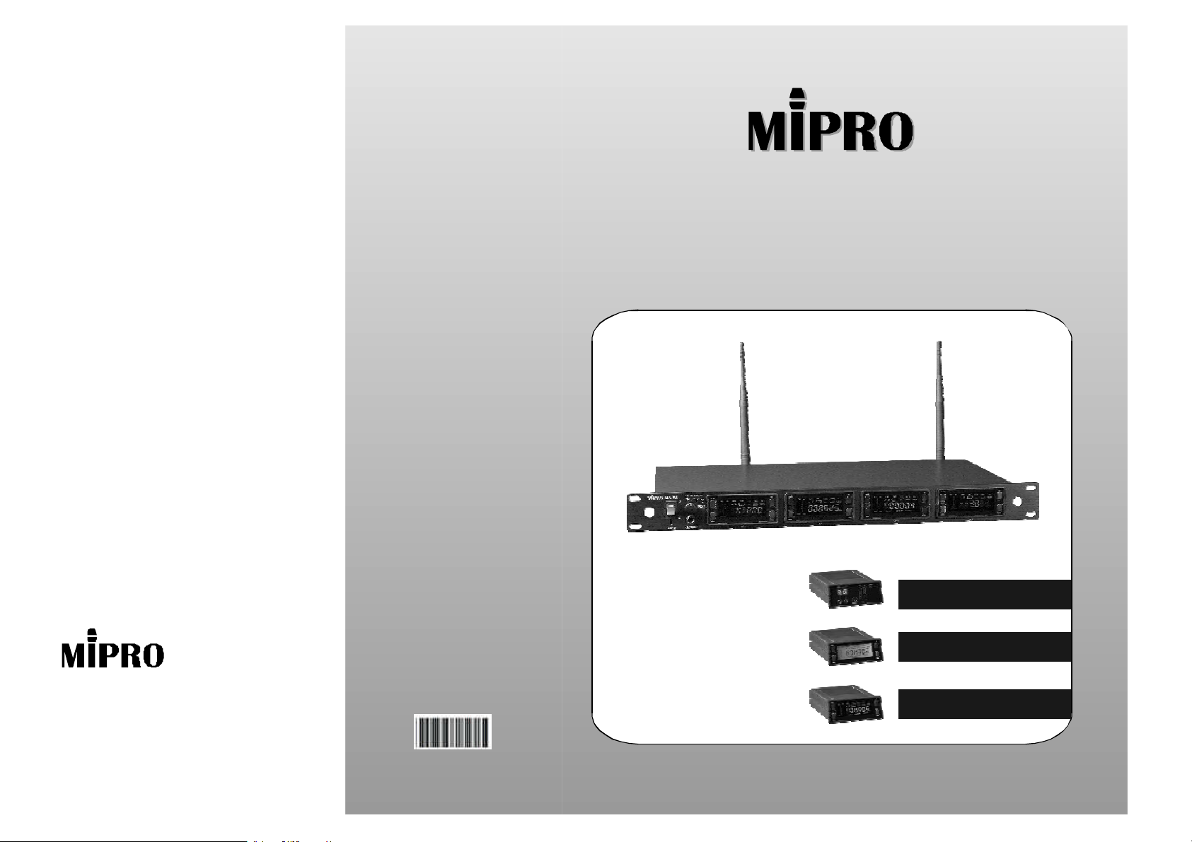
ACTSeries4ChannelsWirelessReceiverACTSeries4ChannelsWirelessReceiver
InstructionManual
ACT-707MA:LEDDISPLAY
ElectronicsCo.,Ltd.
Headoffice:814,Pei-KangRoad,Chiayi,600,Taiwan.
Taipeioffice:5,Lane118,Sung-tehRoad,Taipei,110,Taiwan.
Web-http://www.mipro.com.twE-mail:[email protected]
ACT-707MB:MONOLCDDISPLAY
ACT-707MC:COLORLCDDISPLAY
2CE092
Page 2
CONTENTS
ACTMULTICHANNELWIRELESSRECEIVER
1.INTRODUCTION
1.INTRODUCTION
2.PARTSNAMEANDFUNCTIONS
3.INSTALLATIONOFTHERECEIVER
4.HOWTOASSEMBLEANDDISSEMBLEARECEIVERMODULE
5.COMPUTERNETWORKINTERFACEOPERATION
6.CAUTIONS
1
2-3
4-5
6
7-8
9
Thanksforchoosingthemostadvanced4channelswirelessreceiversystemfrom
MIPRO.
Pleasereadthismanualthoroughlyforcorrectoperatingandoptimalperformance.
ACT-707seriesnotonlyhavethemoststylishprofessionaldesign,butalsoadapt
themostadvancedmodularizedstructuredesign.Eachstandardrackreceivercase
has4slotsenable
Equippedwithswitchingpowersupply,whichcanbeusedwhileconnectedexternallyor
stockinternallyinthestoragecaseonthebackofthereceiver.Thefrontpanelofthe
receiveriswelldesignedforinstantinstallationonthestandard 19-inchrackcase.
IncludedAccessories﹕
①×②×③×Antenna2InstructionManual1PowerCable1
SystemPairings﹕
①
ACT-707A:
SelectfromMIPRO'sUHFPLLhandheldwirelessmicrophonesandbeltpacktransmitters.
②
ACT-707B:
Display)
SelectfromMIPRO'sACThandheldwirelessmicrophonesandbeltpacktransmitters.
③
ACT-707C:
Display)
SelectfromMIPRO'sACThandheldwirelessmicrophonesandbeltpacktransmitters.
④
Whensimultaneoususeofmultichannelsisneeds,pleaserefertothenon-interference
frequencies, pre-arrangedandtestedbyMIPRO,toavoidinterference.
fordifferentreceivermodulesquickassemblyandeasydisassembly.
ACT-707Receiver+ACT-707MA(WirelessReceiverModulewithLEDDisplay)
ACT-707Receiver+ACT-707MB(WirelessReceiverModulewithMONOLCD
ACT-707Receiver+ACT-707MC(WirelessReceiverModulewithColorLCD
0
1
Page 3
ACTMULTICHANNELWIRELESSRECEIVER
2.PARTSNAMEANDFUNCTIONS
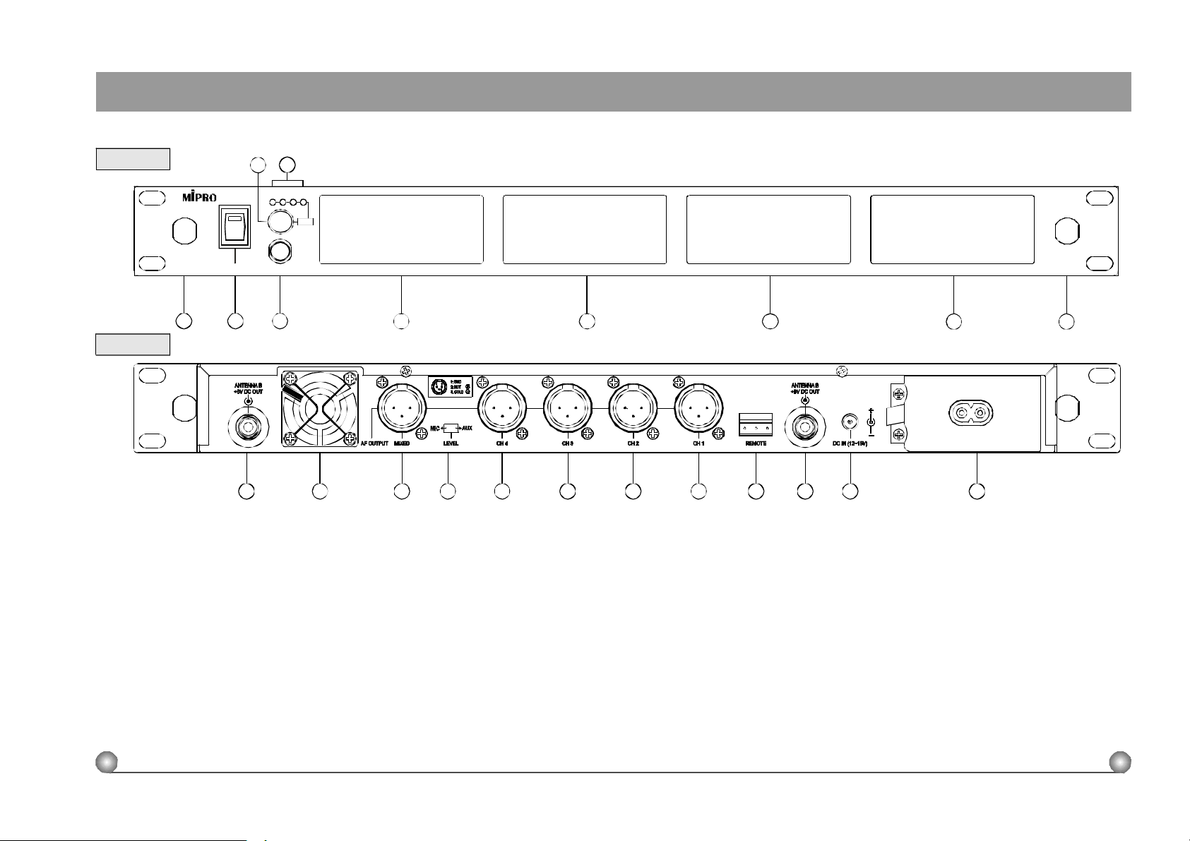
FrontPanel:
4 5
ACTMULTICHANNELWIRELESSRECEIVER
ACT-707
1
0
1
2 3
CH4CH3CH2CH1
PUSH
HEADPHONEPOWER
CH1 CH2 CH3
6
RearPanel:
11 12 1413 1615 17 18 2019 21 22
(1)FrontAntennaAInputConnector:Allowsanoptionalrear-to-frontAntennakitforfrontantenna
placement.
(2)PowerSwitch&Indicator:Whenswitchisturnedon,redindicatorilluminatestodenotenormal
powerstatus.
(3)HeadphoneJack:Toconnecttoastereoheadphonetomonitoroutputsignals.
(4)HeadphoneVolumeControlandModuleSelector:Pushestheknobtoselectthemoduleyou
wouldliketomonitor;turnstheknobtoadjustthevolumeofthestereoheadphone.
(5)ModuleIndicator:Pointsoutselectedmonitoringmodule
(6)ReceiverModule1:FirstReceiverModuleSlot[Ch. 1]
(7)ReceiverModule2:SecondReceiverModuleSlot[Ch.2]
(8)ReceiverModule3:ThirdReceiverModuleSlot[Ch.3]
(9)ReceiverModule4:FourthReceiverModuleSlot[Ch.4]
(10)FrontAntennaBInputConnector: Allowsanoptionalrear-to-frontAntennakitforfrontantenna
placement.
2
CH4
9 107 8
(Fig.1)
(Fig.2)
(11)RearAntennaBinputConnector:BAntennaconnectorcanbeinstalledwithantennadirectlyand
providespowerforantennabooster.
(12)HeatSink:Pleasekeepitadequatelyventilated.
(13)MixedAFOutputSocket:AbalancedoutputsocketformixedAFsignalsfromallinstalled
modules;2outputlevelstoswitchfrom.
(14)MixedAFOutputLevelSwitch:CanswitchtheoutputtoMICorAUXlevel.
(15)OutputSocketforModule4:Thebalancedoutputsocketforfourthreceivermodule.[Ch.4]
(16)OutputSocketforModule3:Thebalancedoutputsocketforthirdreceivermodule.[Ch.3]
(17)OutputSocketforModule2:Thebalancedoutputsocketforsecondreceivermodule.[Ch.2]
(18)OutputSocketforModule1:Thebalancedoutputsocketforfirstreceivermodule.[Ch.1]
(19)ComputerNetworkInterfaceConnector:Networksockettoconnecttothecomputerizedsystem-
monitoringprogram.
(20)RearAntennaAinputConnector:AAntennaconnectorcanbeinstalledwithantennadirectlyand
providespowerforantennabooster.
(21)DCInputSocket:Theinputsocketfor12VoltDCpower.Pleasenotethatthepolarityofthe
centralpininthesocketispositive(+).
(22)ACPowerSocket:TheinputsocketforACpower.UsesACpowerrangingfrom90ACVto264
ACVwithoutchanginganyapplication.
3
Page 4
ACTMULTICHANNELWIRELESSRECEIVER
ACTMULTICHANNELWIRELESSRECEIVER
3.INSTALLATIONOFTHERECEIVER
1:GND
2:HOT
3.COLD
MIC AUX
CH3AFOUTPUT MIXED LEVEL
CH4 CH2 CH1
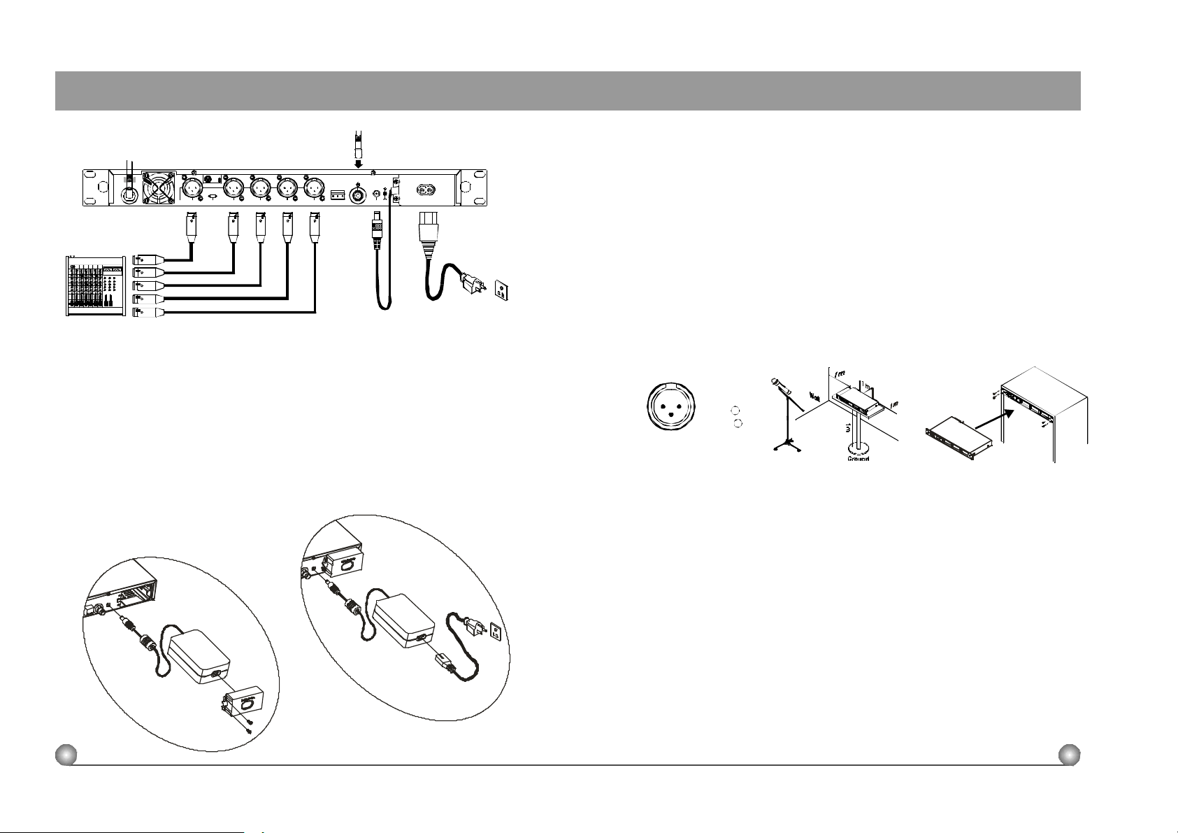
1.Install2separateantennasontheantennasockets(11),(20)ontherearpanel.
Illustratedinfigure3.
2.Connectingthepowersupply:WhenusingACpowersupply,attachthefemaleend
ofthepowercordtothereceiver(22)andplugthemaleendtotheACpower
outlet.Afterward,taketheDCoutputcordfromthepowermoduleandpluginto
theDCinputsocket(21).Illustratedinfigure3.
3.ACT-707adaptsswitchingpowersupplymodule.Theswitchingpowersupplynot
onlycanbeusedwhileconnectedexternally(figure4),butalsostockinternallyin
thestoragecaseonthebackofthereceiver (figure3).
InternalPowerSupplyAssembly
ANTENNAB
+8VDCOUT
REMOTE DCIN(12~15V)
ExternalPowerSupplyUnit
(Fig.3)
4.AudioOutputConnection
MixedOutput:Balancedoutputsocket(XLR)mustconnecttothebalancedinputsocketofthe
mixer.ThisoutputsocketgeneratesthemixedoutputofCh.1~Ch.4andtheoutput
sensitivitycanbeadjustedtoAUXlevelorMIClevelbythelevelswitchontherightsideof
thesocket.Generallyspeaking,AUXlevelistocoordinatetheinputsensitivityofelectricguitar
amplifier.
IndependentOutputs:Therearefourbalancedoutputsocketsforindividualoutputsof
CH1~CH4.Allusebalanced(XLR)outputsocketsandtheoutputsensitivitieshadbeenpre-
settomicleveltocoordinatetheinputlevelofthemixer(MIClevelaswell).(Figure5
5.AntennaSocket:Theantennasocketprovides8VoltDCpower,whichenableyou
topairwithMIPRO'santennaboosterdirectly.Whentheconnectingcableforthe
antennaismorethan10meter,itisrecommendedtoinstallantennaboosterto
makeupthesignallosscausedbythecableandtoensurethesensitivityof
reception.
1:GND
21
3
2:HOT
3:COLD
+
-
(Fig.5) (Fig.6) (Fig.7)
6.Toensurebestreceptionpossible,receivermustbeinstalledatleastonemeter
aboveground.Inaddition,thedistancebetweentransmitterandreceivermustbe
morethanonemeterandawayfromnoise.(Showsinfigure6)
7.Onthefrontpanelofthereceiver,4openingsarepre-drilledforinstantinstallation
onthestandard19-inchrackcase.(Showsinfigure7)
(Fig.4)
4 5
Page 5
ACTMULTICHANNELWIRELESSRECEIVER
ACTMULTICHANNELWIRELESSRECEIVER
4.HOWTOASSEMBLYANDDISASSEMBLYARECEIVERMODULE
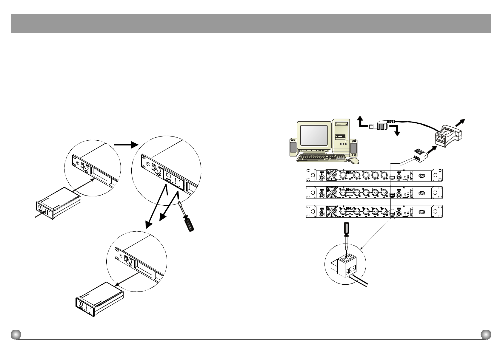
1.Whenassemblythereceivermodulewiththereceiver,alignthereceivermodule
withtheinsertslotinthereceiverandpushingentlyfollowingbythebuilt-inguide
rail.Untilthereceivermodulecomestoafullystop,theinstallationofthereceiver
moduleiscompleted.(Illustratedbelow)
2.Whentakingthereceivermoduleapartfromthereceiver,haveaPhillips-type
screwdriveravailablefirst.Insertthescrewdriverintheindentationunderneaththe
frontalframeofthereceivermoduleandpushoutslightlytoreleasethemodule
fromthelockingmechanism.Oncethemoduleisfreefromlockingmechanism,
onecanretrievethemoduleeasily.
Align
Push
Pull
5.COMPUTERNETWORKINTERFACEOPERATION
1.ExceptforACT-707MAreceivermodule,bothreceivermoduleswithLCDdisplay
[ACT-707MBandACT-707MC]havethemostadvancefunctionofcomputer-
network-interfacedcontrollingsystem.
2.WiringInstruction
Connectthenetworkinterfaceremoteconnector(19)onthebackofthereceivertothe
interfaceconverter(requiresatleast2linkingcablesforeachpairing).Then,useRS-232
cableconnectstheconvertertotheRS-232COMPORTonthecomputer.
RX1
RX2
RX3
PC
TOPCKEYBOARDCONNECTOR
TOKEYBOARD CONNECTOR
Wire(+)
Wire(-)
TOPCRS-232COMPORT
CONVERTER
Pull
RemovethedetachableconnectingbasefromtheREMOTEconnector(19),andpluginthe
(Fig.8)
leadingwires[Wire(-)andWire(+)].UsePhillips-typescrewdrivertorotatethescrewand
tightenthewires.(Showsinfigure9.)Oncecompleted,putthebasebacktothereceiverand
parallelconnectwithotherreceiversbeforefinallyconnectedtotheconverter.
6
Wire(-)
Wire(+)
(Fig.9)
7
Page 6
ACTMULTICHANNELWIRELESSRECEIVER
ACTMULTICHANNELWIRELESSRECEIVER
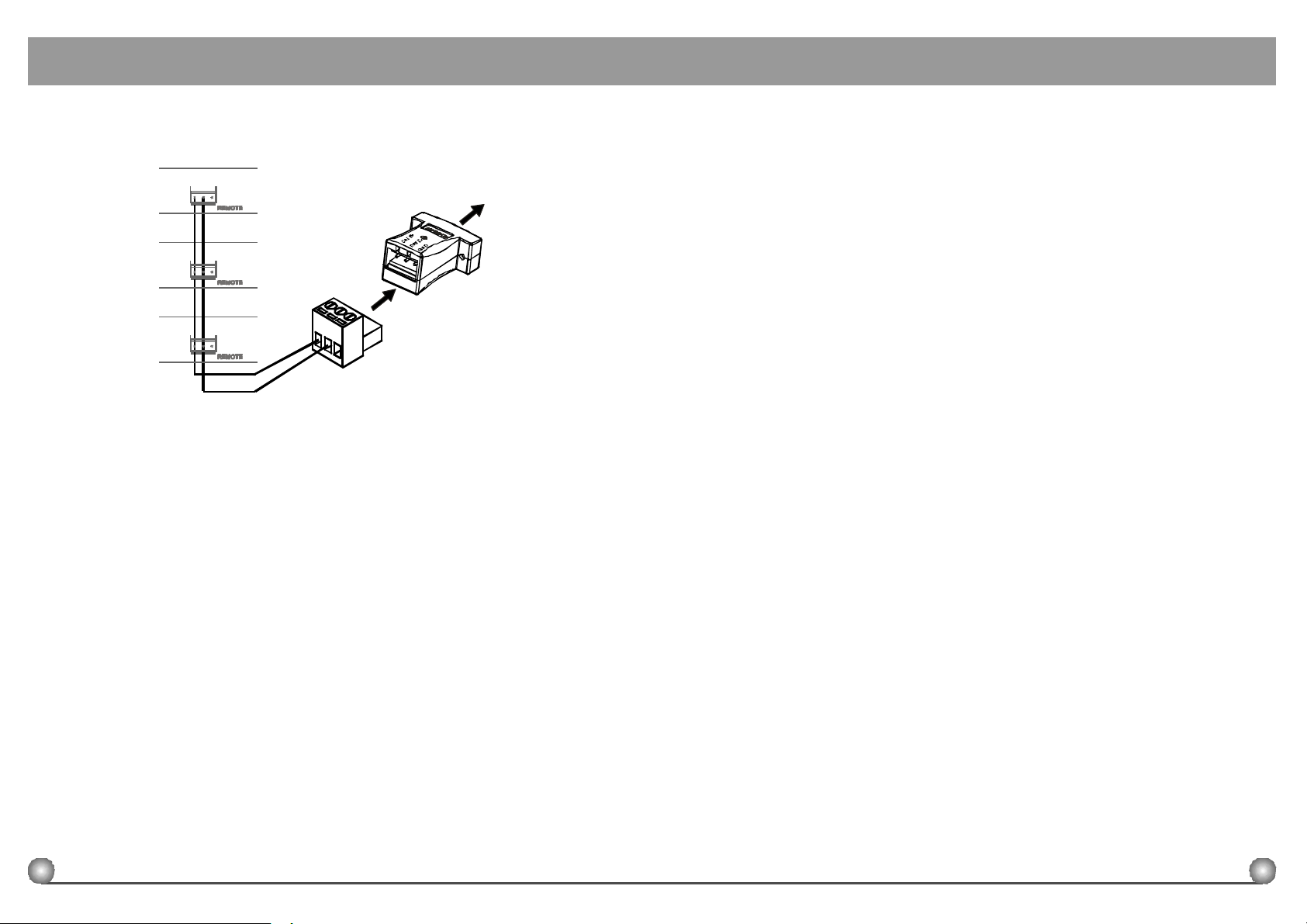
③ Thisinterfacesystemadaptsparallelconnection.Therefore,ittakesonly2linkingwiresto
completetheconnectiontotheconverterofthewholesystem.
RX1
TOPCRS-232COMPORT
RX2
CONVERTER
RX3
④
Thissystemcanconnectupto64receivermodulesforsimultaneousoperation.Hence,if4
receivermodulesareinstalledineachACT-707,thiscontrollingsystemcanoperateupto
16ACT-707receivers.
⑤
Thoughlongerthedistanceis,worsethestabilitywillbe;nevertheless,thenetwork
connectingcablecanstilloperatewhileitis3.However,itisour
recommendationtokeepthecableunder100meterslongtoensurehigh-speed
transmission.
⑥
PleaserefertotheLCDmodule'susersmanualforsoftwareoperation.
Wire(+)
Wire(-)
(Fig.10)
00meterslong
6.CAUTIONS
1.WhenusingDCpowersupply,pleasebeawareoftheoperatingvoltage.Firstof
all,pleasemakesureminimumof12voltscanbeobtainedforfunctionproperly.
However,thepowersupplyshouldnotexceeditsmaximumcapacityof15volts.
Whenthesupplyvoltageismorethan15volts,thesystemwillsuffersevere
internaldamage.Itispreferredthepowersourceisfromaregulatedpowerwith
theminimumcurrentof3A.
2.UseonlyMIPROstandardantennatoensurethesensitivityofthereceiver.
3.Useonlystereoinsteadofmonoheadphoneasthemonitoringheadphone.
4.Antennasockethas8-voltsDCpowersupply;pleasedonotshortthecircuitof
thispart.
8
9
 Loading...