

Page 1

ElectronicsCo.,Ltd.
Headoffice:814,Pei-KangRoad,Chiayi,600,Taiwan.
Taipeioffice:5,Lane118,Sung-tehRoad,110,Taipei,Taiwan.
Web-http://www.mipro.com.tw
E-mail:@mipro.com.twmipro
MR-515
Half19-inchunitwirelessreceiversystem
InstructionManual
2CE095
ELECTRONICSCO.,LTD.
Page 2
WIRELESSRECEIVER
B.RearPanel
Thankyouforselectinghalf19-inchunitnon-diversity
MIPRO
wirelessreceiversystem.Beforeoperatingpleasereadthisinstruction
manualcarefullyandthoroughlyinordertoattainthecorrectoperating
proceduresandachievethebestresults.
Thissystemisdividedintosinglechannelreceiverwithmatchingone
microphonesandindividualvolumecontrols.Thissystemisalso
equippedwith"PILOTONE"andthelatest"NOISELOCK"dual-squelch
circuit,andprovidestheefficacyforeliminatetherandomnoise
interferencewhenthereceiverisatstandbystate.
Thissystemincludesthefollowingaccessories:
①×AudioOutputCable1
③×Antenna2
②×InstructionManual1
④×AC/DCAdapter1
1.PartsNameandFunctions
A.FrontPanel
Antennainrear
POWER
Antennainrear
Antennainfront
-
(5)
-
(5)
+
AFOUTPUT
(6)
AFOUTPUT
(6)
MIC
MIC
LEVEL
(7)
LEVEL
(7)
SQ
ANT
AUX
(9)(8)
SQ
AUX
(8)
+
(Fig.2)
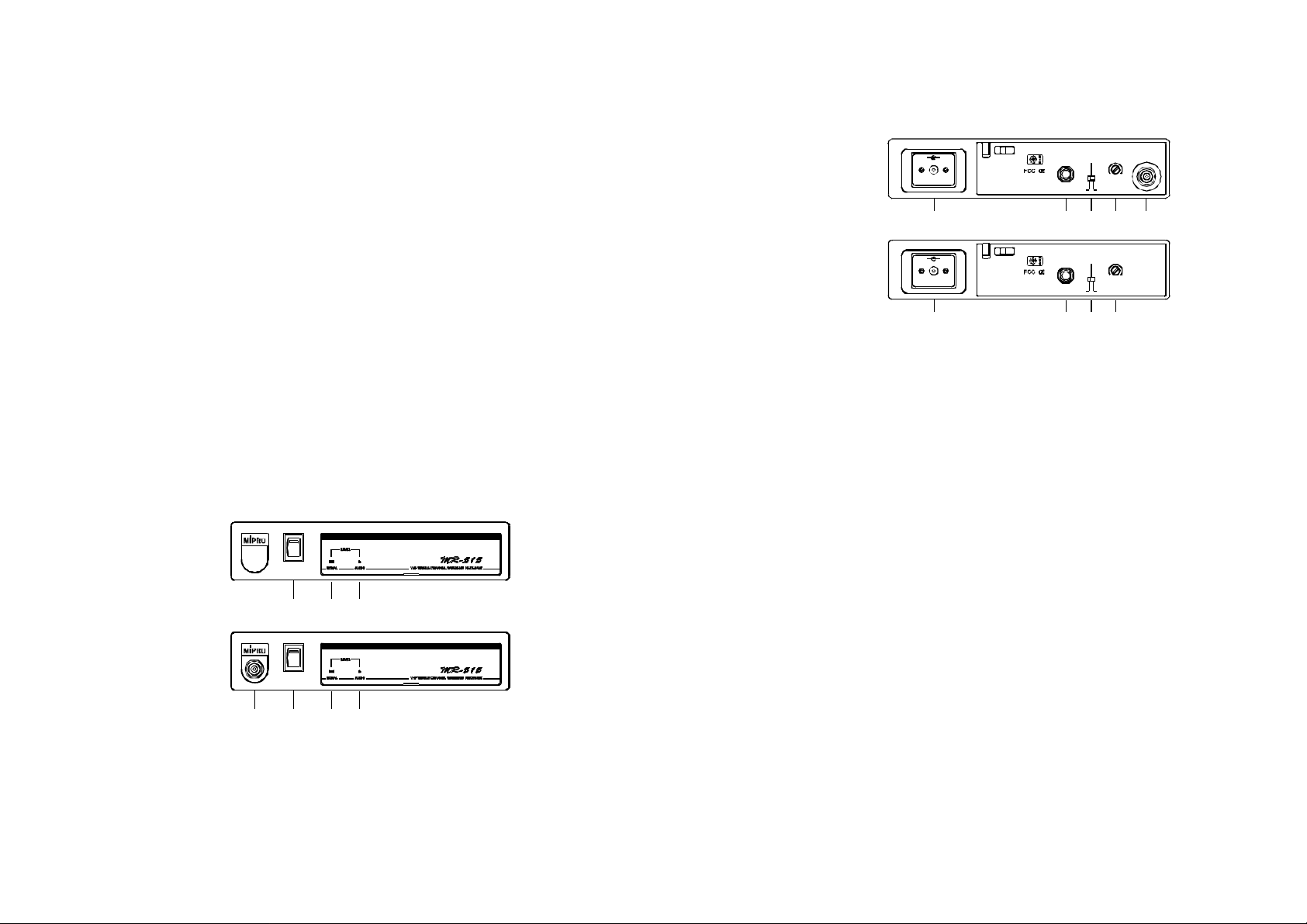
(5)DC12VInputJack:Toconnect12VDCfromtheAC/DCadapter.
(6)UnbalancedAudioOutputJack:With1/4"PhoneJackprovidesaudio
outputsignalfromthisjacktotheamplifier.
(7)UnbalancedLevelSwitch:"MIC"selectionisfor"Microphone-level"
output. "AUX" selection is for "Line-out" level output.A
(8)SquelchAdjusters:AdjustthesquelchleveltoeliminatetheRFnoise
interferenceatreceiverstand-bystate.
(9)AntennaInputConnectors:ForrearAntennaPlacement.
(2)
(3)
(4)
Antennainfront
POWER
(2)
(1)
(1)AntennaInputConnector:ForFrontAntennaPlacement.
(2)PowerSwitch&Indicator:Whenswitchisturnedon,redindicator
illuminatestodenotenormalpowerstatus.
(3)RFSignalIndicator:IndicatesreceivingtransmittingRFsignals.
(4)AudiosignalIndicator:Indicatesthemicrophonesignal.
(3)
(4)
-1- -2-
(Fig.1)
Page 3
2.Installationofthereceiver
+
-
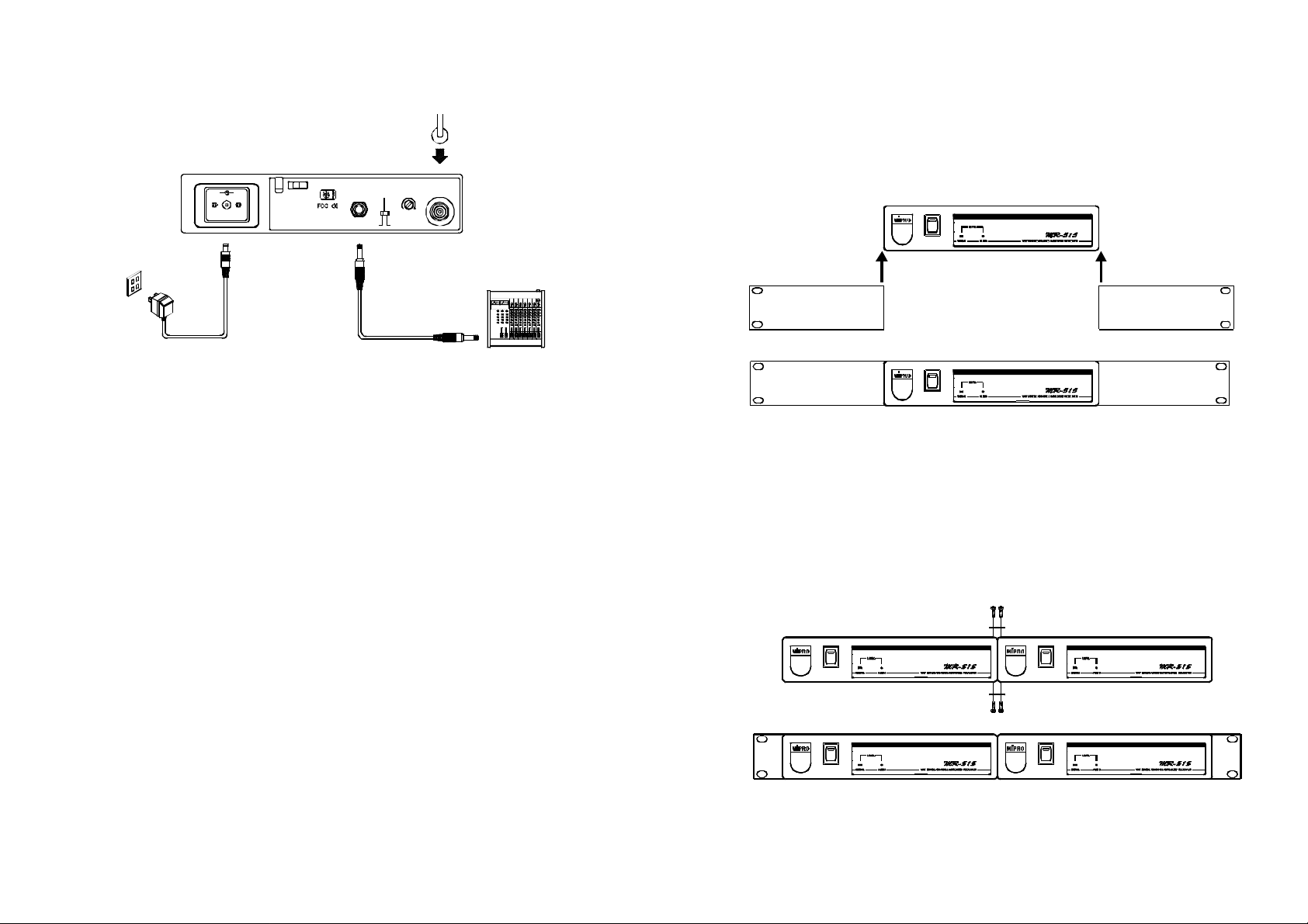
1.Installantennainrear(1)oratthefront(9).Extendantennatothe
fullestposition.seefig.3.
2.ConnecttheAC/DCadaptercabletoDC12VINPUTJACK(5),
thenplugtheadapterunitintoanappropriateACoutletwithcaution
tothecorrectvoltageunderbothACoutletandadaptermarked,as
showninfig.3.
3.AudioOutputConnection:
(a)UnbalancedLevelSwitch(7)SettingPosition:Wheninputsthe
unbalancedoutputofareceiverinto"AUX-IN"inputjackofamixer
oramplifieror"ElectricGuitar",switchtheLevelSwitch(7)tothe
right"AUX"position.Lowsensitivitymayoccurifswitchtothewrong
position.Wheninputstheunbalancedoutputofareceiverintothe
"MIC-IN"inputjackofamixeroramplifier,switchtheLevelSwitch(7)
totheleft"MIC"position.Overloaddistortionmayoccurifswitchto
thewrongposition.Whenusingelectricguitar,don'tuse"MIC"position
asitmayhavegeneratedinsufficientlevel.
(b)UnbalancedOutput:Usingaudiooutputcableattachedwith"PHONE
PLUG"type,connectoneandfromtheunbalancedoutputjack(6)of
thereceiver,andtheotherendtothe"AUX-IN"inputjackofthe
amplifier,asshowninFig.3.
(C)GuitarOutput:Usingaudiooutputcableattachedwith"PHONEPLUG"
type,unbalancedoutputjack(6)ofareceiver,andtheotherendtothe
guitarinputjackofaguitaramplifier.SwitchtheLevelSwitch(7)to
"AUX"position.
AFOUTPUT
SQLEVEL ANT
MIC
AUX
(Fig.3)
3.Two19/2-inchunitsreceiverinstallation
1.Singlehalf-rackreceiver
(a)Pushtherackmountearoptionalaccessory(FB-11)upwardsuntilitis
firmlyattachedtothereceiver.(fig.4)
POWER
POWER
2.Dualhalf-rackreceivers
(a)Positiontheconnectingplatesbetweenthetopandbottomofthetwo
receiversandtighten.(Fig.5)
(b)Afterjoiningthe2receiverstogether,pushtheoptionalaccessoryrack
mountears(FB-12)upwardsuntiltheyfirmlyattachedtothereceiver.
(Fig.5)
POWER
POWER
POWER
POWER
(Fig.4)
(Fig.5)
-3- -4-
Page 4
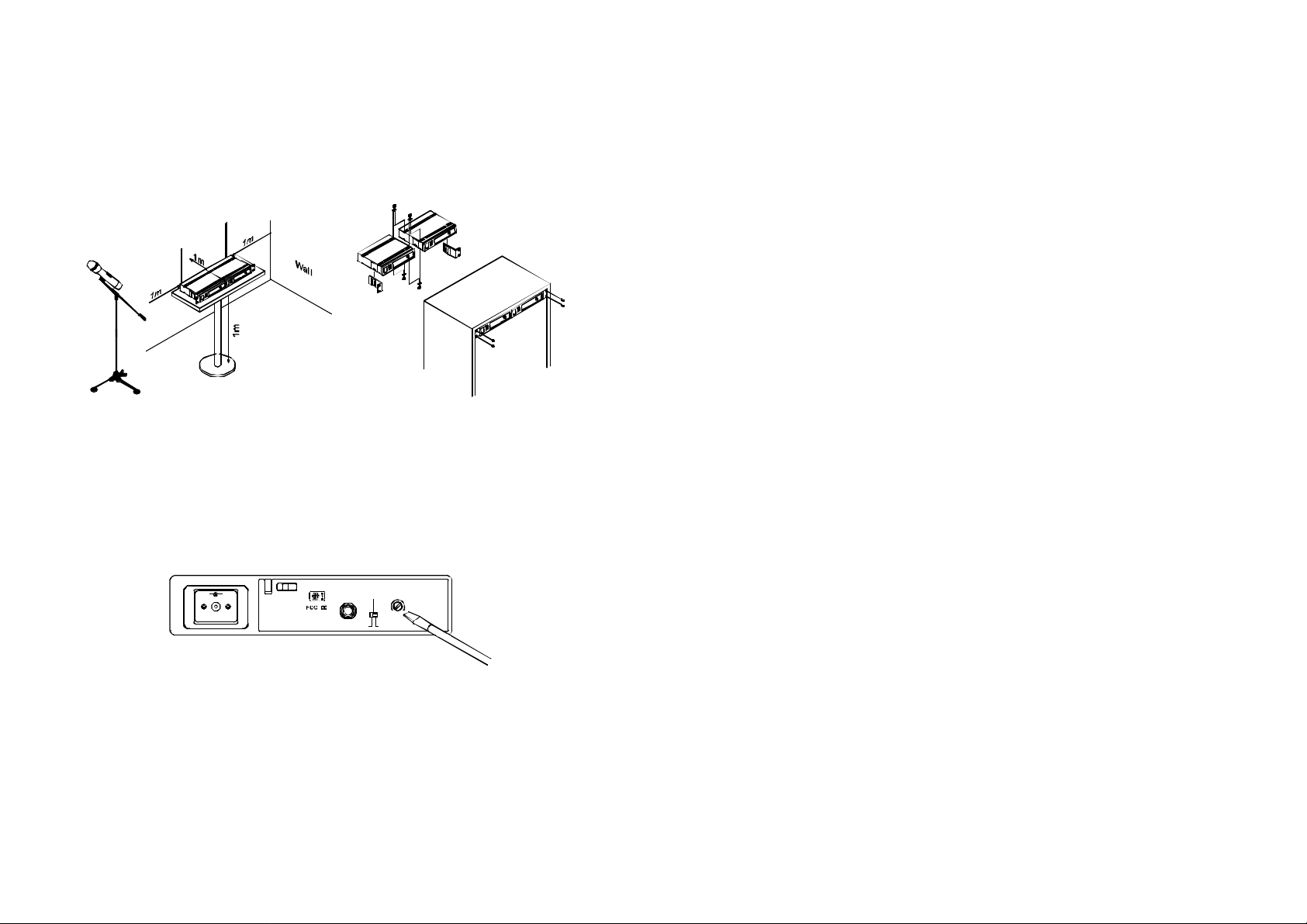
3.Makesurethatthesystemperformscorrectlybyplacingthesystem
awayfromnoisesources.Placethereceiveratleast1meterabove
thegroundandawayfromnoisesources.Placethemicrophoneat
least1meterawayfromthereceivingantenna,asshowninFig.6.
4.Aftercompletion,itcanberackmountedintoanEIAstandardrack
case.Shownonfigure7.
Ground
(Fig.6) (Fig.7)
4.OperationInstructions
1.Turnvolumecontrolsofthereceiverandmixerinusetoaminimum
settingbeforeturnonthemicrophonesortransmitters.After
switchesonthereceiver,thepowerswitchredindicatorilluminates
todenotenormalpowerstatus.
3.Undernormalcircumstances,theSIGNALindicatorlightsupwhena
microphoneortransmitteristurnedonnearthereceivertoindicate
thereceiverisreadyfornormaloperation.Oncesoundstothe
microphoneandtheAUDIOLEDindicators(4)willglowaccording
tothestrengthofsoundlevel.IfnoLEDglowsornosoundoutputs,
thesystemisnotfunctionproperly,thusitmustbechecked.
4.ReceiverandAmplifierVolumeAdjustment:
(a)UnbalancedAudioOutput:Switchthelevelswitch(7)onthereceiver
rearpaneltotheleftposition"MIC",thenadjustvolumecontrolofthe
amplifierormixertoobtainanappropriatesoundlevelofthe
microphone.
(b)Toobtainsamesensitivityandvolumelevelofbothwiredandwireless
microphonesinamixeroramplifierthathasmorethan2microphone
inputsockets,onecanadjustthewiredmicrophonevolumecontrolin
themixeroramplifier.Afterreachingdesiredsoundlevel,connectto
theAFoutputsocketofreceiver.Pleasenotethattheunbalanced
volumeswitchonthebackofthereceivershouldswitchto"MIC"
position.
(c)Ifthereceiveroutputlevelisadjustedexcessively,itwillcausethe
saturationdistortionofthemixeroramplifierwhenthemicrophoneis
loud.
+
-
AFOUTPUT
SQLEVEL
MIC
AUX
(Fig.8)
2.IfSIGNALLEDindicators(3)ofthereceiverlightonbefore
switchesonthemicrophoneortransmitter,itindicatesthereceiveris
receivinginterferencesignals.ThissystemhasPitlotoneand
NoiseLockdual-squelchfeaturesandnonoiseoutputwilloccur.If
multiplechannelsareusedandbothSIGNALandAUDIOLEDs
glowandinterferencenoiseappear,simplyadjusttheSquelch
controls(8)clockwiseuntilAUDIOsignalindicatorstoextinguish.
(Fig.8).However,byadjustingthesquelchcontrols,itaffectsthe
sensitivitylevelofthereceiver,therefore,shortentheoperating
distanceanddecreasesthestability.
-5- -6-
Page 5
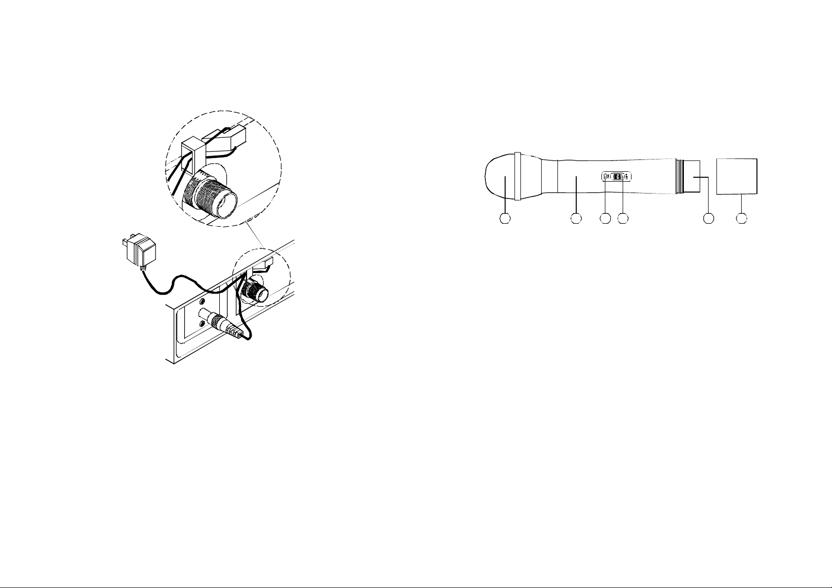
5.Plugthecableofthemainsunitintodcsocketonthereceiver'sback
panel.Threadthecablethroughthecablegripasshownontheabove
illustration.Thecablegrippreventstheconnectorfrombeingpulled
offbyaccident.
HANDHELDWIRELESSMICROPHONE
Microphoneismodulardesign.(1)Grille(2)Housing(3)Battery
Indicator(4)PowerOn/OffSwitch(5)BatteryCompartment(6)Battery
Cap.Italsoincorporates"Piltone&NoiseLock"dual-squelchto
eliminatenoiseinterference.
(Fig.9)
5.Caution
1.Sincetheinstallationofantennainfluencestheoperatingefficiency
ofthereceiver,themostimportantruleistominimizedthedistance
betweenreceivingantennaandmicrophoneasshortaspossiblefor
betterreceptionandperformance.
2.TheexternalDCpowersupplyshouldnotbebelow12V,otherwiseit
wouldnotworkproperly.Ifitisover15V,somecomponentsofthe
receiverwillbedamaged.
3.Whenusingmulti-channelsystemssimultaneously,properchannel
frequencyselectionisveryimportanttoavoidmutualinterference.
1 3
2 654
(Fig.1)
PartsNameandFunctions
1.Grille:Protectscartridgeandprevents"breathingandwindPOP
noises".
2.Housing:Upperportiontobeconnectedtocapsulemodule.Internally,
itholdstransmitterPCBandbatterycompartment.
3.BatteryStatusIndicator:Indicatesthepoweron/offandbattery
status.WhenpowerswitchisturnedON,theredLedindicator
flashesbriefly,indicatingnormalbatterystatus.Ifnoflashoccurs,it
haseithernobatteryorthebatteryisdrainedorinstalledincorrectly.
Afterpoweronandtheindicatorstayslighted.Itwarnsthebattery
isweakandanewbatteryreplacementisthusnecessary.
4.PowerOn-offSwitch:SlidetheswitchforpowerONforusageor
OFFwhennotinuse.
5.BatteryCompartment:Designedtoaccommodateonepiece9V
battery.
6.BatteryCap:Coversbatteryinthebatterycompartment.
-7- -8-
Page 6
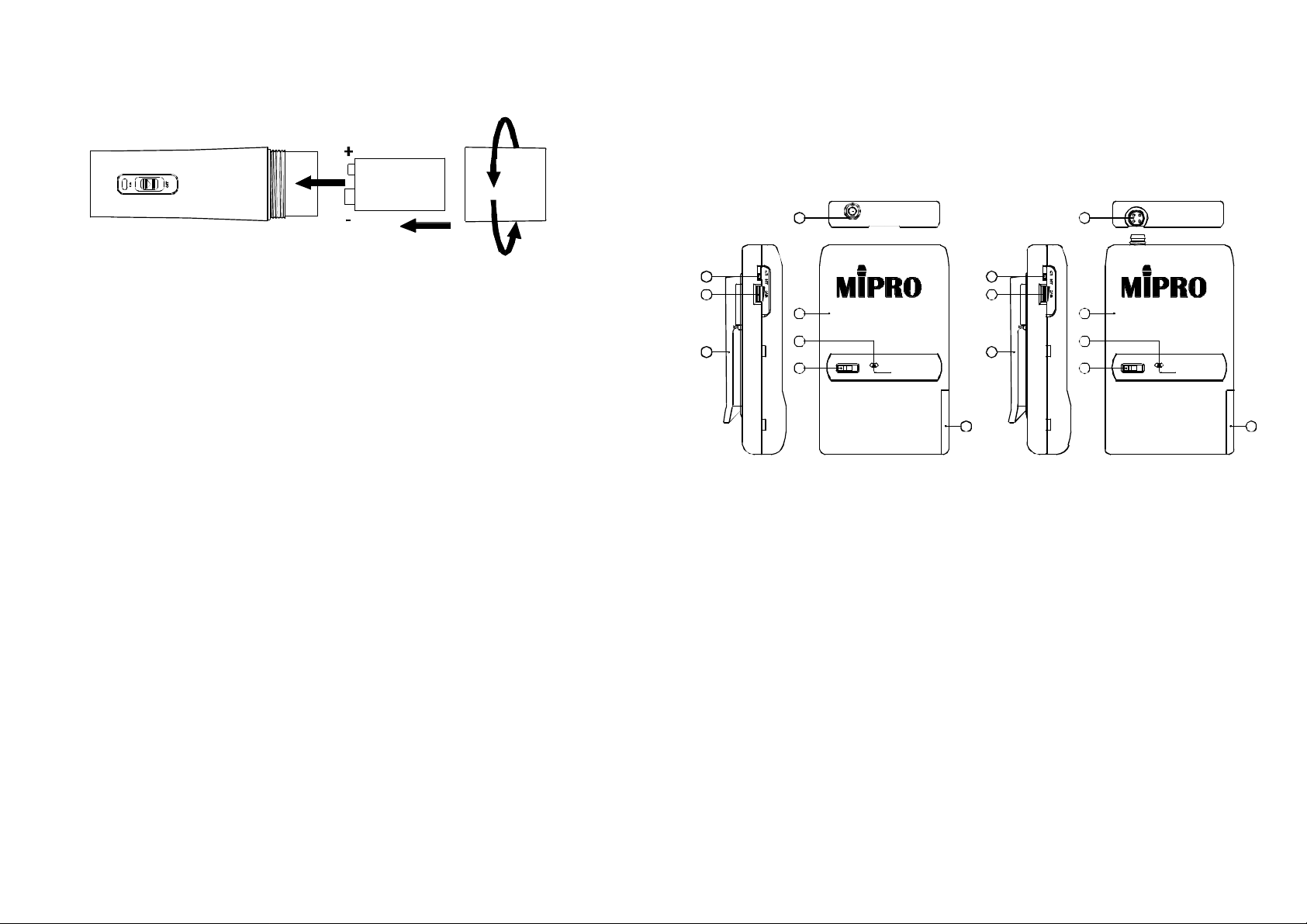
1.BatteryInsertion
BeltPackTransmitter
1.PartsNameandFunctions
1.Unscrewbatterycapincounter-clockwisedirection(6).
2.Inserta9Vbatteryintothebatterycompartmentaccordingtothe
correctpolarityasshowninFig.2.Themomentthebatterytouches
theterminalsofcompartment,theindicatorwillflashbriefly(3).
Thismeansthepolarityiscorrect.However,ifnoflashoccurs,this
indicateswronginsertionorbatteryisdead.Pleasere-insertthe
batteryaccordingtoitscorrectpolarityorexchangeafreshbattery.
2.OperatingInstructions
1.Whenmicrophoneisswitchedon:
Atthemomentofthepowerisswitchedon,theindicatorwillflash
brieflyindicatingnormaloperation.
(a)Whenpoweron:
SIGNALledindicatorofreceiverglows.
(b)Afterpoweron:
Themoreglowsindicatereceivedsignalstrengthisstrong.
(c)DuringUsage:
AUDIOLEDonthereceiverwillglowwiththevolumeofthe
microphone.
(d)Whenthemicrophoneisnotinuse:
Makesuretoturnoffthemicrophonetoextendthelifespanof
thebattery.Removethebatteryfromthebatterycompartmentif
microphoneisnotinuseforanextendedperiodtoavoidbattery
acidleakageanddamagingtheinternalPCBandsprings.
(Fig.2)
(PHONEJACK)
MIC
1
3
4
7
11
8
OFF ON
9
BATT.LOW
5
6
11
10
(4PINJACK)
MIC
2
7
8
OFF ON
9
BATT.LOW
1.PhoneJackInputConnector:Connectstophonejack3.5mmconnector.Allow
forlavalierandheadsetmicrophones.
2.4-PinJackInputConnector:ConnecttoMIPRO4-pinconnector.Allow5
differentinput.(See5waysofconnectiononAFInputConnections)
3.LocklevelSwitch:Whenswitchtoupwardposition,itwillfixandlocked
volumeatmaximumlevelmakingthevolumecontrolnowunadjustable.When
switchisatdownwardposition,itcanfreelyadjusttheaudioinputlevelwith
thevolumecontrol.
4.VolumeControl:Adjuststheaudioinputlevel.
5.GT/MTSwitch:SwitchGTpositionforelectricguitarusageONLY.Gain
Control is irrelevant for T? Switch to T or condenser microphone,G M f
wired microphone or Line-in. Gain Control works in T or inputM f
sensitivityadjusting.
6.GainControl:Adjuststhedesirousinputgain.
7.TransmitterHousing:PackagesthePCBandbattery.
8.BatteryStatusIndicator:Indicatesthepoweron/offandbatterystatus.
(a)Whenpowerswitchisturnedon:TheLEDindicatorflashesbriefly,
indicatingnormalbatterystatus.
(b)WhenREDlightilluminatesateitherpoweronorduringusage:Thebattery
levelislow,therefore,anewbatteryreplacementisthusnecessary.
10
-9- -10-
Page 7
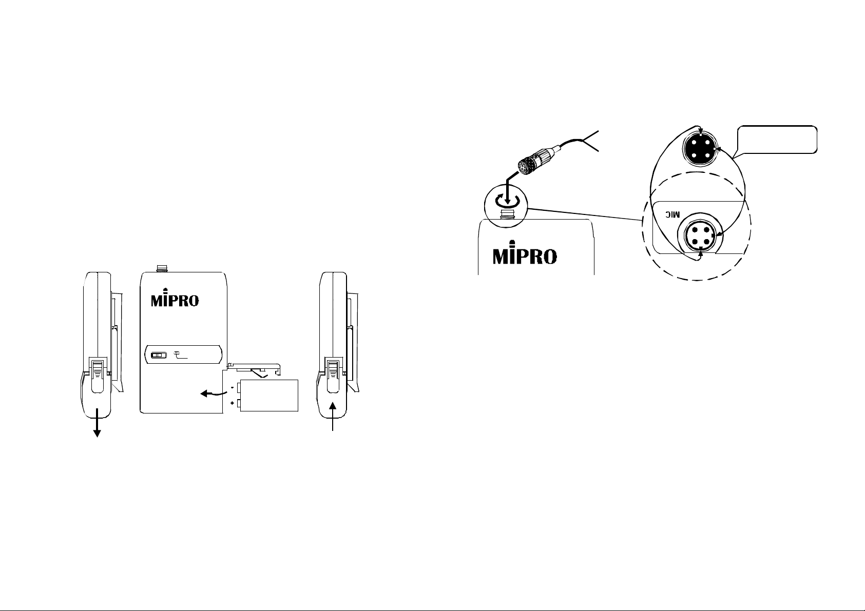
9.PowerSwitch:SwitchtoONpositionforoperation.SwitchtoOFFposition
whennotinuse.
10.BatteryCompartmentandCover:Accommodatesonepiece9Vbattery.
11.DetachableBeltClip:Pullslightlytowardsyouandpushdownaccordingto
thearrowdirectiontoreleasethebeltclip.
2.OperatingInstructions
1.Pushdowntoopenthebatterycompartmentcover(10)asshownin
Fig.1.
2.Inserta9Vbatteryintothebatterycompartmentaccordingtothe
correctpolarityasshowninFig.2.Thenpushuptoclosethe
batterycompartmentasshowninFig.3.
OFF ON
BATT.LOW
6.4-PinJack:Alignandinserttheplugtojackaccordinglyandtighten
itintheclockwisedirectionasshowninfigure4.
CapsuleConnectort
Headset
Lavalier
7.PhoneJack:Inserttheplugaccordinglyandtightenitinthe
clockwisedirection.
Pleaseaimofthefillister
andinserttheconnector
(Fig.4)
(Fig.1) (Fig.2) (Fig.3)
3.TheLEDindicatorflashesbrieflywhenpoweronindicatingnormal
batterystatus.Ifnoflashoccursithaseithernobattery,thebatteryis
drainedorinstalledincorrectly.Changeaccordingly.
4.PhoneJack:Adjustthevolumecontroltodesiredvolume(4)andfix
andlock(4)volumelevel.Nowvolumecanbeadjustedbythe
receiverandnotbythetransmitteritself.
5.4-PinJack:VolumecanbeadjustedbyGaincontrol.Gaincontrol
hasnoeffectwhenswitchtoGT(Guitar)usage.
-11- -12-
Page 8

3.AF4-PinInputConnectionMethods
(1)2-WireElectretcondensermicrophoneCapsule
SHIELD
AUDIO
PIN
1
2
3
4PIN
4
PLUG
(2)3-WireElectretcondensermicrophoneCapsule
SHIELD
AUDIO
BIAS
PIN
1
2
3
4PIN
4
PLUG
(3)DynamicMicrophone
PIN
1
2
3
4
1 4
2 3
4PIN
PLUG
3
2 1
SHIELD
AUDIO
(4)ElectricGuitar
SHIELD
AUDIO
PIN
1
2
1 4
2 3
3
4PIN
4
PLUG
1 4
2 3
1 4
2 3
(5)Line-in(Impedance8KATT.10dB)Ω
SHIELD
AUDIO
-13-
PIN
1
2
4
1
3
2
3
4PIN
4
PLUG
 Loading...