

Page 1
Disposal
Disposetheunusabledeviceaccordingtovalidregulations.
Disposalofspentbatteries/accumulators
Youarerequiredbylawtoreturnallspentbatteries. Disposingofused
batterieswithdomesticwasteisprohibited!
Batteries/NiCadcellscontainingtoxinsaremarkedby
accompanyingsymbolsthatrefertotheprohibitionof
disposalwithdomesticwaste.Thedesignationsforthe
decisiveheavymetalsare:=cadmium,=mercury,
=lead.Youmayreturnspentbatteries/accumulatorsfree
Pb
2005-08-13
Bydoingso,youfulfilthelegalrequirementsandcontributetothe
conservationofourenvironment!
ofchargetotherecyclingcentres,ouroutletsoranywhere
elsewherebatteries/accumulatorsaresold.
CdHg
ACT-707DEChannelWirelessReceiverDual
ACT-707DEDualChannelWirelessReceiver
InstructionManual
ElectronicsCo.,Ltd.
Headoffice:814,Pei-KangRoad,Chiayi,600,Taiwan.
Taipeioffice:5,Lane118,Sung-tehRoad,100,Taipei,Taiwan.
Web-http://www.mipro.com.tw
E-mail:@mipro.com.twmipro
Page 2

CONTENTS
DUALCHANNELRECEIVER
DUALCHANNELRECEIVER
1.INTRODUCTION
2.PARTSNAMESANDFUNCTIONS
3.INSTALLATIONOFTHERECEIVER
4.RECEIVEROPERATINGPROCEDURES
5.SWITCHABLECHANNELSFUNCTIONS
6. ACTBUTTON
7. CAUTIONS
HANDHELDWIRELESSMICROPHONE
1.PARTSNAMESANDFUNCTIONS
2.BATTERYINSERTION
3.OPERATINGINSTRUCTIONS
4.CAUTIONS
BELTPACKTRANSMITTER
1
2-3
4-5
6
7
7
8
10
11
11
11
1.INTRODUCTION
Thanksforchoosingthemostadvancedmultichannelwirelessreceiver
systemfromMIPRO.
Pleasereadthismanualthoroughlyforcorrectoperatingandoptimal
performance.
Intoday'saudioprofessionals,thedemandforusinglotsofmulti-channel
wirelessmicrophonesystemssimultaneouslyisgreatlyincreasing.
Furthermore,theywouldliketoseeprofessionalsystemshavethecapability
ofeasyfrequencyagility,morenon-interferingchannelsandinterference-free
operation.
ACT-707DE,housesinaninternationalstandard1-rackcase,hasLED
panelthatclearlydisplayschannels,RFandAFmeters.Ithasan"AutoScan"
buttontoautosearchfornon-interferencechannelswithasimpletouchofa
button.Concurrently,asimple1-touchonthe"ACT"buttonwilltherefore
providesrapidandprecisechannelsettingofthetransmitter,avoidingpossible
errorsormechanicalbreakdowns.Thissystemisperfectforsinglesystem
usageunderallprofessionalapplications.Spacesaving,stableperformance,
easytooperateandcouplewithunbeatablepricesmakeitanattractive
package.
IncludedAccessories﹕
①×②
Antennas2 AudioOutputCable1
③
InstructionManual1Rack-mountBrackets1-pair
× ④×
×
1.PARTSNAMESANDFUNCTIONS
2.OPERATINGINSTRUCTIONS
3.AF4-PININPUTCONNECTIONMETHODS
4.BATTERYINSERTION
5.CAUTIONS
12-13
13
14
15
15
0
1
Page 3
DUALCHANNELRECEIVER DUALCHANNELRECEIVER
2.PARTSNAMESANDFUNCTIONS
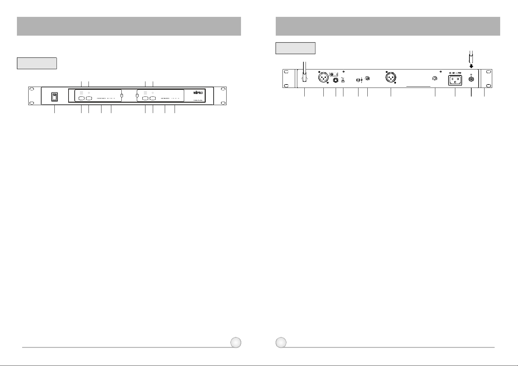
FrontPanel:
(12)(13)
POWER
(1) (2)(3)(4)(5)
SCAN SCANACT ACTRF RFAUDIO AUDIO
SIGNAL SIGNAL
A B
(8)(9)(10)(11)
(1)PowerSwitch&Indicator:Whenswitchisturnedon,redindicator
illuminatestodenotenormalpowerstatus.
(2)(8)AudioSignalLevelIndicator:Indicatetheaudiosignallevel.
(3)(9)RFSignalLevelIndicator:IndicatetheRFsignalstrengthreceived.
(4)(10)ACTButton:Tosetupmicrophonefrequencytomatchreceiver
frequency.
(5)(11)ScanButton:Pressoncetoselectreceivingchannelandautoscan
thewholebandwidthtoavoidinterferencechannel.
(6)(12)ACTIndicator:IndicateifACTfunctionisactivated.
(7)(13)ChannelIndicator:Todisplaysystem'sreceivingchannel.
(6)(7)
ACT-707DE
(Fig.1)
RearPanel:
+8VDCBIAS
(14)
1:GND
2:HOT
3:COLD
MIC LINE
SQB BALANCEDOUTADCIN(12~15V)LEVELMIXOUTANTENNAB BALANCEDOUTB SQA ANTENNAA
(15)
(16)(17) (18) (19) (20) (21) (22) (23)
MADEINTAIWAN
+8VDCBIAS
(24)
(Fig.2)
(14)RearAntennaBinputConnector:BAntennaconnectorcanbe
installedwithantennadirectlyandprovidespowerforantenna
booster..
(15)(20)BalancedAudioOutputJack:WithCannon/XLRtypeconnector
providesbalancedaudiooutputsignalfromthisjacktotheamplifier.
Switchbetween"LINE"and"MIC"fordifferentpurposes.
(16)UnbalancedAudioMixedOutputJack:With1/4PhoneJack
λ
providesthemixedunbalancedaudiooutputsignalfromthisjackto
theamplifier.Switchbetween"LINE"and"MIC"fordifferentpurposes.
(17)UnbalancedLevelSwitch:"MIC"selectionisfor"Microphone-level"
output."LINE"selectionisfor"Line-out"leveloutput.
(18)DC12VInputJack:Toconnect12VDCfromtheAC/DCadapter.
(19)(21)SquelchAdjuster:AdjustthesquelchleveltoeliminatetheRFnoise
interferenceatreceiverstand-bystate.
(22)ACInputJack:Toconnect85~265VoltsACpower.
(23)RearAntennaAinputConnector:AAntennaconnectorcanbe
(24)RackmountBracket:ToinstallthereceiverintoanEIA19-inch
2 3
installedwithantennadirectlyandprovidespowerforantenna
booster.
standardrackcase.
Page 4
DUALCHANNELRECEIVER DUALCHANNELRECEIVER
3.INSTALLATIONOFTHERECEIVER
+8VDCBIAS
1:GND
2:HOT
3:COLD
MIC LINE
SQB BALANCEDOUTADCIN(12~15V)LEVELMIXOUTANTENNAB BALANCEDOUTB SQA ANTENNAA
MADEINTAIWAN
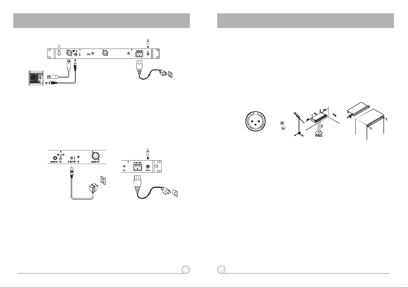
1.Install2separateantennasontheantennasockets(14),(23)ontherear
panel.Illustratedinfigure3.
2.PowerOutputConnection:
(a)ConnecttheAC/DCadaptercabletoDC12VINPUTJACK(18),thenplug
theadapterunitintoanappropriateACoutletwithcautiontothecorrect
voltageunderbothACoutletandadaptermarked,asshowninfig.4.
(b)WiththeappropriateACpowercableconnectsfromACInputJack(22)toan
ACoutletunderthemarkedvoltage85~265V,asshowninFig.5.
+8VDCBIAS
(Fig.3)
(b)UnbalancedOutput:Usingaudiooutputcableattachedwith"PHONEPLUG"
type,connectoneendfromtheunbalancedoutputjack(16)ofthereceiver,
andtheotherendtothe"LINE-IN"inputjackoftheamplifier,asshownin
Fig.3.
(c)BalancedOutput:Usingaudiooutputcablesattachedwith"XLR"or
"Cannon"type,connectoneendfromthebalancedoutputjacks(15)(20)of
thereceiver,andtheotherendtothe"MICIN"inputjackofthemixeror
amplifier,asshowninFig.3.(Thecharacteristicofthe3-pinconnectorisas
showninFig.6
(d)GuitarOutput:Usingaudiooutputcableattachedwith"PHONEPLUG"type,
plugoneendfromtheunbalancedoutputjackofareceiver,andtheother
endtotheinputjackofaguitaramplifier.SwitchtheLevelSwitch(17)to
"LINE"position.
1:GND
21
2:HOT
3
3:COLD
(Fig.6)
(Fig.8)(Fig.7)
4.Toensurebestreceptionpossible,receivermustbeinstalledatleastone
meteraboveground.Inaddition,thedistancebetweentransmitterand
receivermustbemorethanonemeterandawayfromnoise.(Showsin
figure7)
5.Onthefrontpanelofthereceiver,4openingsarepre-drilledforinstant
installationonthestandard19-inchrackcase.(Showsinfigure8)
(Fig.4)
(Fig.5)
3.AudioOutputConnection:
(a)UnbalancedLevelSwitch(17)SettingPosition:Wheninputstheunbalanced
outputofareceiverinto"AUX-IN"inputjackofamixeroramplifieror
"ElectricGuitar",switchtheLevelSwitch(17)totheright"LINE"position.
MICsensitivitymayoccurifswitchtothewrongposition.Wheninputthe
unbalancedoutputofareceiverintothe"MIC-IN"inputjackofamixeror
amplifier;switchtheLevelSwitch(17)totheleft"MIC"position.Overload
distortionmayoccurifswitchingtothewrongposition.Whenusingelectric
guitar,don'tuse"MIC"positionasitmayhavegeneratedinsufficientlevel.
4 5
Page 5
DUALCHANNELRECEIVER DUALCHANNELRECEIVER
4.RECEIVEROPERATINGPROCEDURES
1.Setthevolumeofthemixertoitsminimumbeforeturningonthereceiver
ortransmitters.
MIC LINE
SQBDCIN(12~15V)LEVELMIXOUTBALANCEDOUTB
(Fig.9)
2.IfSIGNALLEDindicators(3)(9)ofthereceiverlightonbeforeswitching
onthemicrophoneortransmitter,itindicatesthereceiverisunder
interferenceofnoises.ThemoreLEDslightonthemoreseverityof
interference.ThissystemhasPitlotoneandNoiseLockdual-squelch
featuresandnosuddennoiseburstoutwilloccur.Ifmultiplechannels
areusedandbothSIGNALandAUDIOLEDsglowandinterference
noisesappear,simplyadjusttheSquelchcontrols(19)(21)clockwiseuntil
AUDIOsignalindicatorstoextinguish.(Fig.9).However,byadjustingthe
squelchcontrols,itaffectsthesensitivitylevelofthereceiver,therefore,
shortentheoperatingdistanceanddecreasesthestability.
3.Undernormalcircumstances,theSIGNALindicatorlightsupwhena
microphoneortransmitteristurnedonnearthereceivertoindicatethe
receiverisreadyfornormaloperation.Oncespeakintothemicrophone
andtheAUDIOLEDindicators(2)(8)willglowaccordingtothestrength
ofsoundlevel.IfnoLEDglowsornosoundoutputs,thesystemisnot
functionproperly,thusitmustbechecked.
4.Themicrophoneoutputlevelneedstobeadjustedattheamplifieror
mixer.Noneed toadjustatthereceiveritself.
5.SWITCHABLECHANNELSFUNCTIONS
1.Functions:
(a)ThissystemincorporatesadvancedPLLsynthesizedoscillatordesign.
Preprogrammedwith16switchablefrequencies.Allowtheusertofreely
selectanyofthepreprogrammedfrequencies.
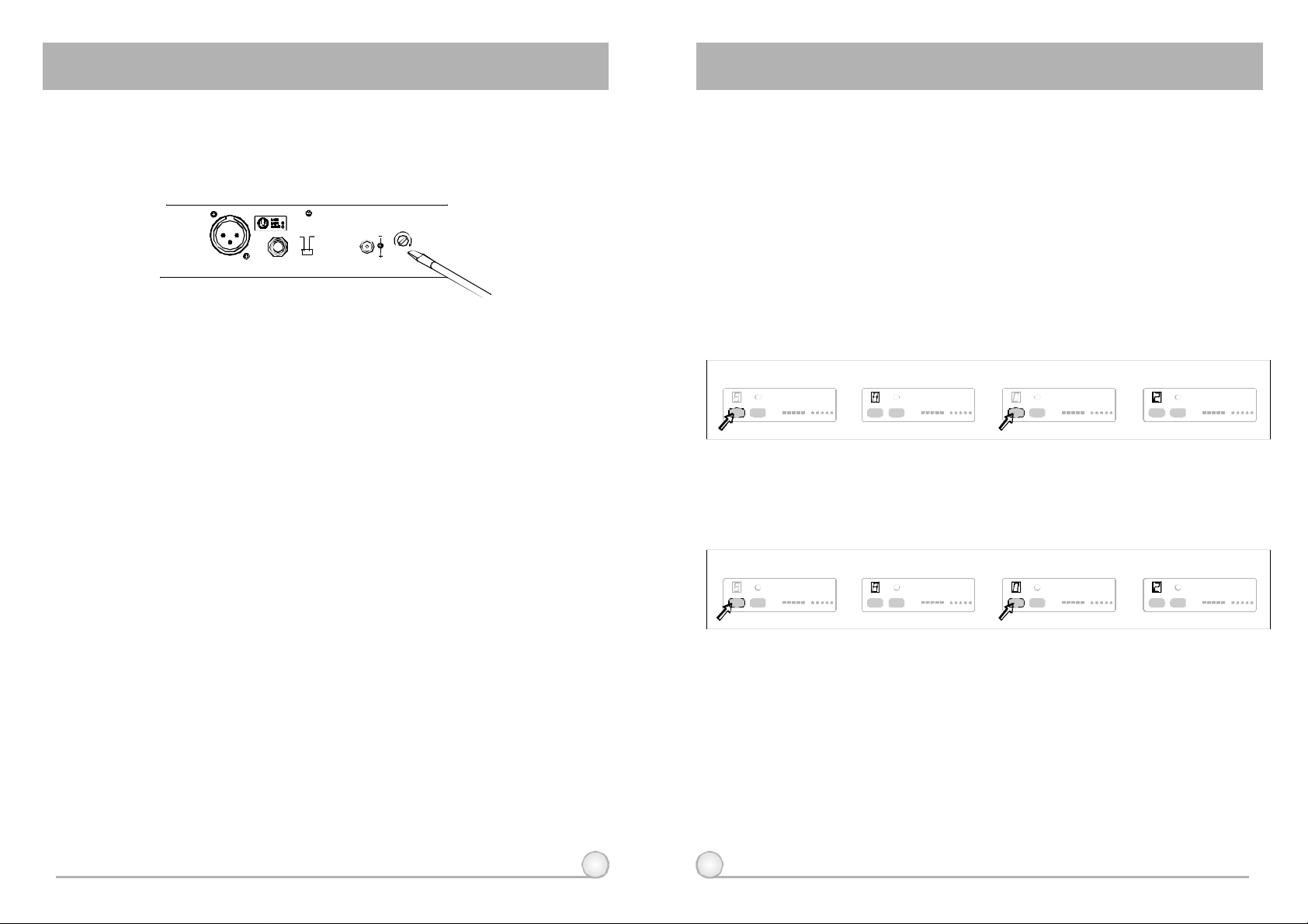
2.HowToSelectaFrequency:
(a)HoldingdowntheSCANbutton(5)(11)
AutoScanningFrequencySet-up:
for1second.ReleasethebuttonwhennumericLED(7)(13)flashes.Itwill
flashatotalof6times.ToactivatetheAutoScanfunction,presstheSCAN
buttononcewithinthese6times.Anopenfrequencywillautomaticallybe
scannedandsaved/locked.*NoteAutoScanfunctionworksonlyduring
numericLEDflashingandwithin6times.
Pressandhold"SCAN"button
a)
for1second.
SCAN ACT RF AUDIO
(b)HoldingdowntheSCANbutton(5)(11)for1
SIGNAL
ManualFrequencySet-up:
b)
LEDdisplayflashes.
SCAN ACT RF AUDIO
SIGNAL
second.ReleasethebuttonwhennumericLED(7)(13)flashes.Itwillflasha
totalof6times.Toselectanyofthe16frequenciesinorderlyformat,press
theSCANbuttonandholduntilthedesiredfrequencyisselected.This
frequencywillautomaticallybesaved/locked.
Pressandhold"SCAN"button
a)
for1second.
SCAN ACT
SIGNAL
RF AUDIO
b)
LEDdisplayflashes.
SCAN ACT
SIGNAL
RF AUDIO
3.Changechannelwhen:
(a)Existingchannelisbeinginterferedorchannelismalfunction.
(b)Selectchannelformultiplenon-interferenceusage.
Press"SCAN"buttonagainandrelease
c) d)
willautoscanforanopenfrequency.
SCAN ACT RF AUDIO
Press"SCAN"buttonandhold,
c) d)
frequencywillchangeeverytwoflashes.
SCAN ACT
SIGNAL
SIGNAL
RF AUDIO
Whendoneitwillautosaved/locked.
SCAN ACT RF AUDIO
Whendoneitwillautosaved/locked.
SCAN ACT
SIGNAL
SIGNAL
RF AUDIO
4.Cautionwhilechangingchannels:
6 7
(a)Whenmultiplechannelsareutilizeddonotchangechanneltoavoidexiting
channelinterference.
(b)Whennumericknobreaches"_"itindicatesanemptychannel.Proceeduntil
anumericnumberappears.
Page 6
DUALCHANNELRECEIVER DUALCHANNELRECEIVER
6.ACTBUTTON
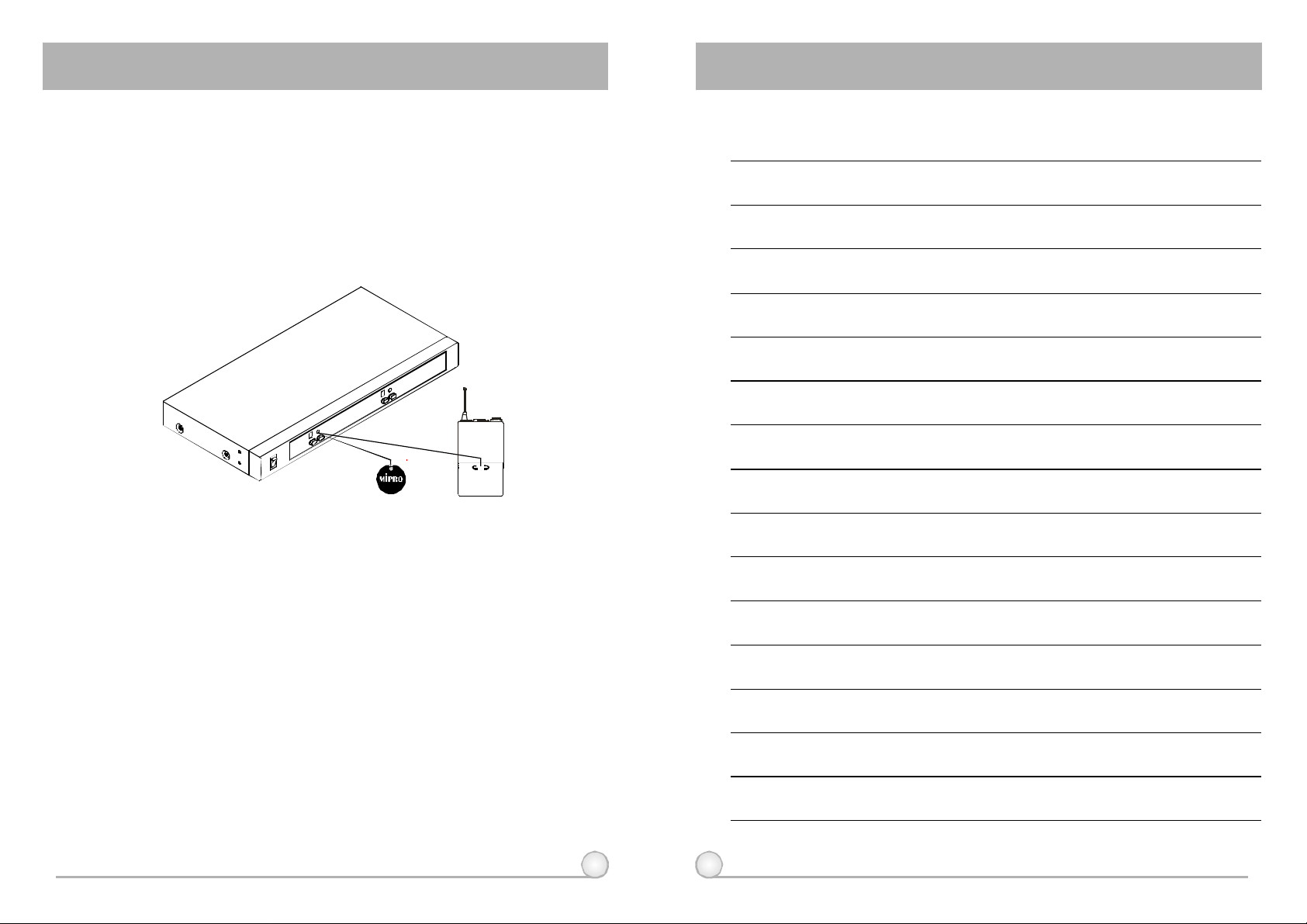
1.Press"ACT"button(4)(10)onthefrontpanelofreceiveronceandthe
systemisreadyfor"ACT"function.
2.Positionthe"ACT"markingofthetransmitterabout20cm(12-inch)
towardsthe"ACT"button(4)(10)onthereceiverasillustratedin
belowfigure.
3.ACTfunctionwillbedeactivatedautomaticallyoncethetransmitter
frequencyislockedon.
ACT
7.CAUTIONS
NOTE﹕
1.Sincetheinstallationofantennainfluencestheoperatingefficiencyofthe
receiver,themostimportantruleistominimizedthedistancebetween
receivingantennaandmicrophoneasshortaspossibleforbetter
receptionandperformance.
2.TheexternalDCpowersupplyshouldnotbebelow12V,otherwiseit
wouldnotworkproperly.Ifitisover15V,somecomponentsofthe
receiverwillbedamagedduetohighercurrent.Useminimum1Apower
supply.
3.Thissystemutilizescomputertransformer.Itisequippedwith85~265V
switchingpowersupplytoavoidswitchinganditisnotaffectedbypower
instability.
8 9
Page 7
HANDHELDWIRELESSMICROPHONEHANDHELDWIRELESSMICROPHONE
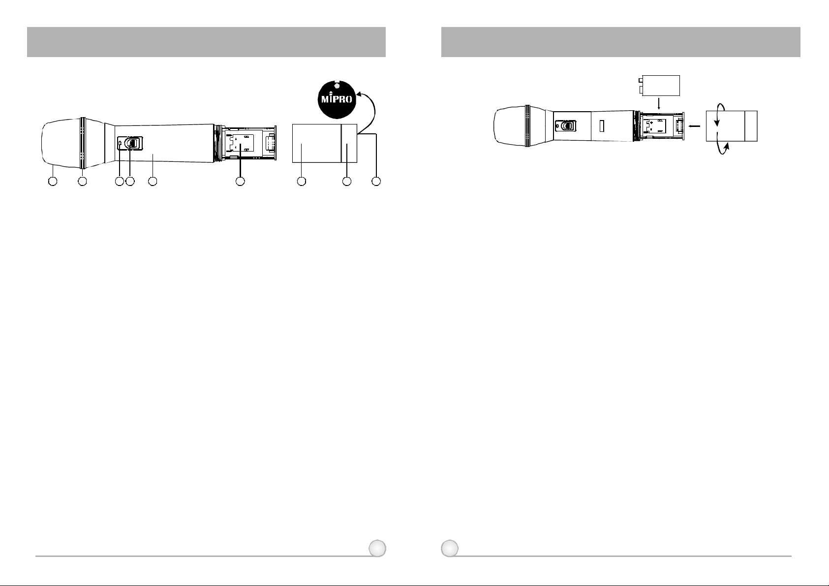
1.PARTSNAMESANDFUNCTIONS
1 2 3 4 5 6 7 98
(Fig.1)
1.Grille:Protectscartridge,prevents"POP"noiseandpreventsmicrophone
fromrollingwithpolygonalshape.
2.ColorRing:Forfrequencydifferentiation.
3.BatteryStatusIndicator:Indicatespoweron/offandthebatterystatus.
WhenthepowerswitchisturnedON,theredLEDsindicatorflashes
briefly,indicatingnormalbatterystatus.Ifnoflashoccurs,ithaseitherno
batteryorthebatteryisdischargedorinstalledincorrectly.Ifafterpower
ontheindicatorstayslighted,itwarnsthatthebatteryisweakandshould
bereplaced.
4.PowerOn-offSwitch:Slidetheswitchfor power"ON"or"OFF".
5.Housing:Upperportiontobeconnectedtocapsulemoduleandbattery.
Internally,itholdstransmitterPCB.
6.BatteryCompartment:Designedtoaccommodateone9Voltbattery.
7.BatteryCap:Coversbatteryinthebatterycompartment.
8.Anti-rollRing:Forfrequencydifferentiation.
9.ActSignalReceptor
2.BATTERYINSERTION
(Fig.2)
1.Unscrewbatterycapinacounter-clockwisedirection(7).
2.Inserta9Vbatteryintothebatterycompartmentaccordingtothecorrect
polarityasshowninFig.2.Themomentthebatterytouchestheterminals,
theindicatorwillflashbriefly(7).Thismeansthepolarityiscorrect.
However,ifnoflashoccurs,thisindicateswronginsertionorthatthe
batteryisdead.Pleasere-insertthebatteryaccordingtoitscorrect
polarityorexchangeitforafreshbattery.
3.OPERATINGINSTRUCTIONS
1.Whenmicrophoneisswitchedon:
Whenthepowerisswitchedon,theindicatorwillflashbrieflyindicating
normaloperation.
2.DuringUsage:
TheAFLEDindicatoronthereceiverwillilluminateaccordingtothe
audiosignalstrengthfromthemicrophone.
3.Whenthemicrophoneisnotinuse:
Makesurethatyouturnoffthemicrophoneafterusetoextendthe
batterylife.Removethebatteryfromthebatterycompartmentif
microphoneisnottobeusedagainforsometime.Ifarechargeable
batterywasused,takeitoutandrechargeit.
4.CAUTIONS
tosetfrequency,microphoneindicator(3)willremainoffafterACTsetupthe
frequency.However,ifindicator(3)isflashing,itmeansreceiverand
transmitterarenotinthesamefrequencyband.Pleasecheckthestickerson
transmitterandreceivertoobserveiftheyaresharingthesamefrequency
bands.
10 11
Undernormaloperation,whenreceiverandtransmitterarepairedtogether
Page 8
BELTPACKTRANSMITTER BELTPACKTRANSMITTER
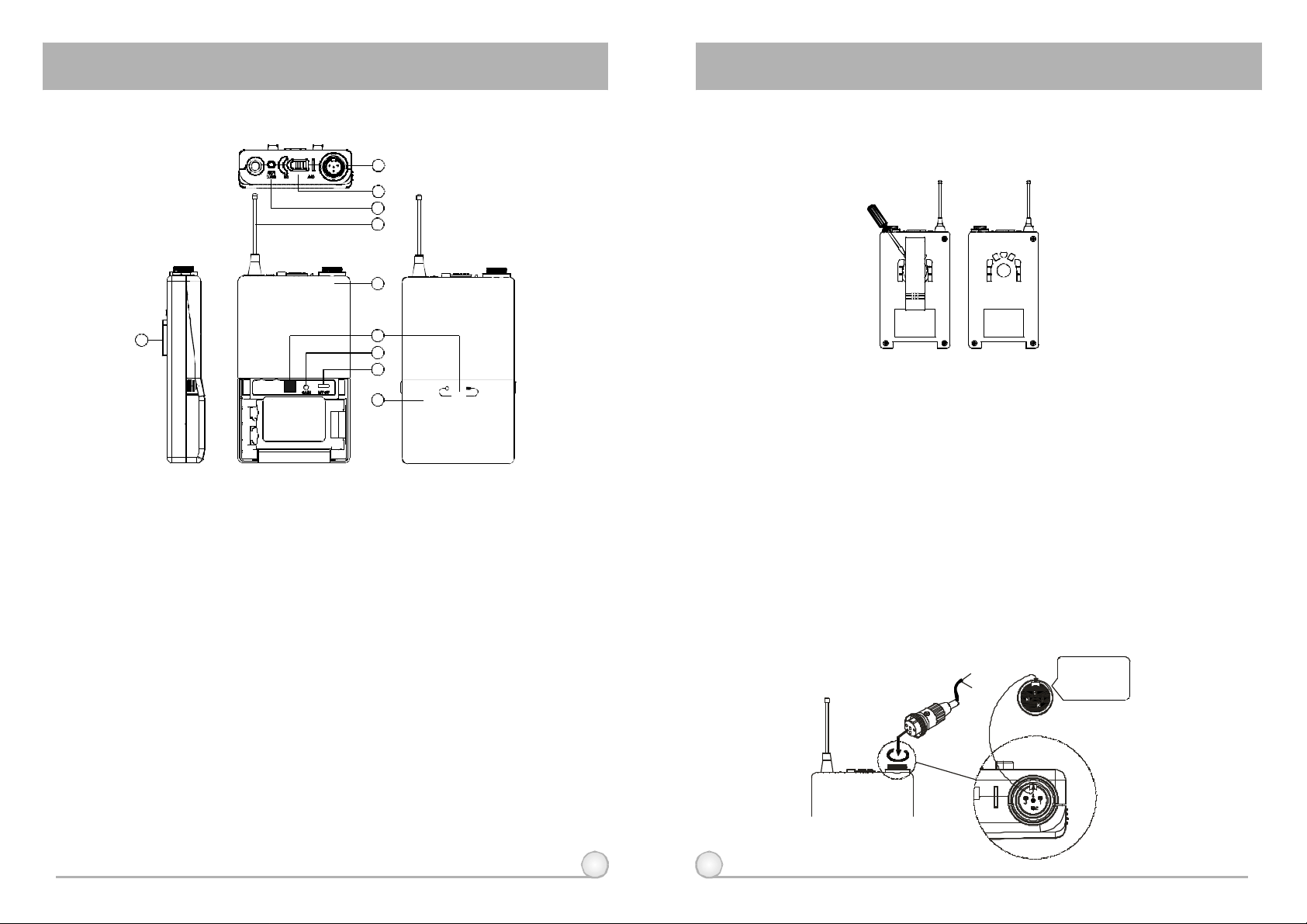
1.PARTSNAMESANDFUNCTIONS
1
2
3
4
5
10
1.AFInputJack:Connectstoeitherlavaliereorheadsetmicrophone.(See
5waysofconnectiononAFInputConnections)
2.PowerSwitch:SwitchtoONpositionforoperation.SwitchtoOFFposition
whennotinuse.
3.BatteryStatusIndicator:Indicatesthepoweron/offandbatterystatus.
(a)Whenpowerswitchisturnedon:TheLEDindicatorflashesbriefly,
indicatingnormalbatterystatus.
(b)WhenREDlightilluminatesateitherpoweronorduringusage:The
batterylevelislow,therefore,anewbatteryreplacementisthus
necessary.
4.TransmittingAntenna:1/4transmittingantenna.
λ
5.TransmitterHousing:PackagesthePCBandbattery.
6
7
8
9
ACT
(Fig.1)
9.BatteryCompartmentandCover:Accommodatesone9Voltbattery.
10.DetachableBeltClip:Allows360degreesrotatingtosuittransmitting
angles.Todetachsimplyuseascrewdriverata45degreeangleto
unfasten.seediagram.
2.OPERATINGINSTRUCTIONS
1.ToadjustGT/MTSwitch(8),andGainControl(7),simplypushdownboth
snaplocksonthesidesofbatterycoverandflipitbackwardstoexpose
theadjustmentpanel.
2.Beforepoweron,ascertainifsamechannelwassetupforbothreceiver
andmicrophone.Ifnotadjusttosamechannelaccordingly.
3.TheLEDindicatorflashesbrieflywhenpoweronindicatingnormalbattery
status.Ifnoflashoccursithaseithernobattery,thebatteryisdrainedor
installedincorrectly.Changeaccordingly.
4.Plugthemicrophoneconnectorintotheinputjack(1)andtightenthe
connectorscrewbyclockwisedirectionasshownin(Fig.2).
CapsuleConnector
Headset
Lavalier
Pleaseaimof
thefillister
andinsertthe
connector
6.ActSignalReceptor
7.GainControl:Adjuststhedesirousinputgain.
8.GT/MTLevelSelectSwitch:SwitchGTpositionforelectricguitarusage
and"LineIn".GainControlisirrelevantfor"GT".Switchto"MT"for
condensermicrophoneorwiredmicrophone.GainControlworksin"MT"
forinputsensitivityadjusting.
12 13
(Fig.2)
Page 9
BELTPACKTRANSMITTER BELTPACKTRANSMITTER
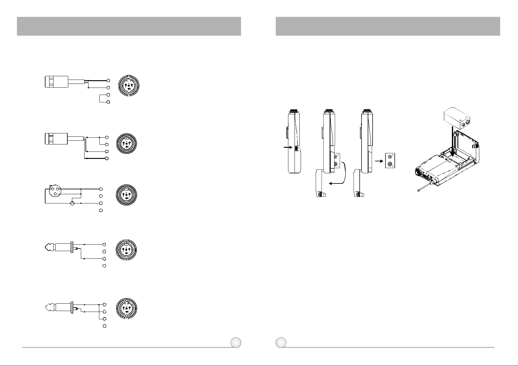
3.AF4-PININPUTCONNECTIONMETHODS
(1)2-WireElectretcondensermicrophoneCapsule
PIN
SHIELD
AUDIO
(2)3-WireElectretcondensermicrophoneCapsule
SHIELD
AUDIO
BIAS
(3)DynamicMicrophone
2 1
3
SHIELD
AUDIO
PIN
1
2
3
4PIN
4
PLUG
PIN
1
2
3
4PIN
4
PLUG
1
2
3
4
4PIN
PLUG
4.BATTERYINSTALLATION
1.Pushingdownbothsnaplocksonthesidesofbatterycovertoopen
batterycover.Takeoutthebatteries.Fig.(3).
2.Inserta9Vbatteryintothebatterycompartmentaccordingtothecorrect
polarityasshowninFig.(4).Thenpushuptoclosethebattery
compartmentasshowninFig.(4).
(Fig.4)(Fig.3)
(4)ElectricGuitar
SHIELD
AUDIO
(5)Line-in(Impedance8KATT.10dB)Ω
SHIELD
AUDIO
PIN
PIN
5.CAUTIONS
1
2
3
4PIN
4
PLUG
1
2
3
4PIN
PLUG
4
14 15
Undernormaloperation,whenreceiverandtransmitterarepairedtogether
tosetfrequency,microphoneindicator(3)willremainoffafterACTsetupthe
frequency.However,ifindicator(3)isflashing,itmeansreceiverand
transmitterarenotinthesamefrequencyband.Pleasecheckthestickerson
transmitterandreceivertoobserveiftheyaresharingthesamefrequency
bands.
 Loading...