

Page 1
Disposal
Disposetheunusabledeviceaccordingtovalidregulations.
Disposalofspentbatteries/accumulators
OPERATINGMANUAL
MR-515
MR-515
Youarerequiredbylawtoreturnallspentbatteries.
Disposingofusedbatterieswithdomesticwasteis
prohibited!
Batteries/NiCadcellscontainingtoxinsare
markedby
accompanyingsymbolsthatrefertothe
prohibitionof
disposalwithdomesticwaste.Thedesignations
forthe
decisiveheavymetalsare:=cadmium,
=mercury,
2005-08-13
Bydoingso,youfulfilthelegalrequirementsandcontribute
totheconservationofourenvironment!
Hg
=lead.Youmayreturnspent
Pb
batteries/accumulatorsfree
ofchargetotherecyclingcentres,ouroutletsor
anywhere
elsewherebatteries/accumulatorsaresold.
Cd
Half19-inchunit
Single-Channel WirelessMicrophoneSystem
ElectronicsCo.,Ltd.
Headoffice:814,Pei-KangRoad,Chiayi,60096,Taiwan.
Taipeioffice:5,Lane118,Sung-tehRoad,Taipei,Taiwan.
Web-http://www.mipro.com.tw
E-mail:@mipro.com.tw
mipro
11075,
2 CE228
Page 2
SINGLECHANNELWIRELESSRECEIVER SINGLECHANNELWIRELESSRECEIVER
ThankyouforselectingMIPROhalf19-inchunitnon-diversitywireless
receiversystem.Beforeoperatingpleasereadthisinstructionmanualcarefully
andthoroughlyinordertoattainthecorrectoperatingproceduresandachieve
thebestresults.
Thissystemisdividedintosinglechannelreceiverwithmatchingone
microphonesandindividualvolumecontrols.Thissystemisalsoequipped
with"PILOTONE"andthelatest"NOISELOCK"dual-squelchcircuit,and
providestheefficacyforeliminatetherandomnoiseinterferencewhenthe
receiverisatstandbystate.
Thissystemincludesthefollowingaccessories:
①×AudioOutputCable1
③×Antenna1
②×InstructionManual1
④×AC/DCAdapter1
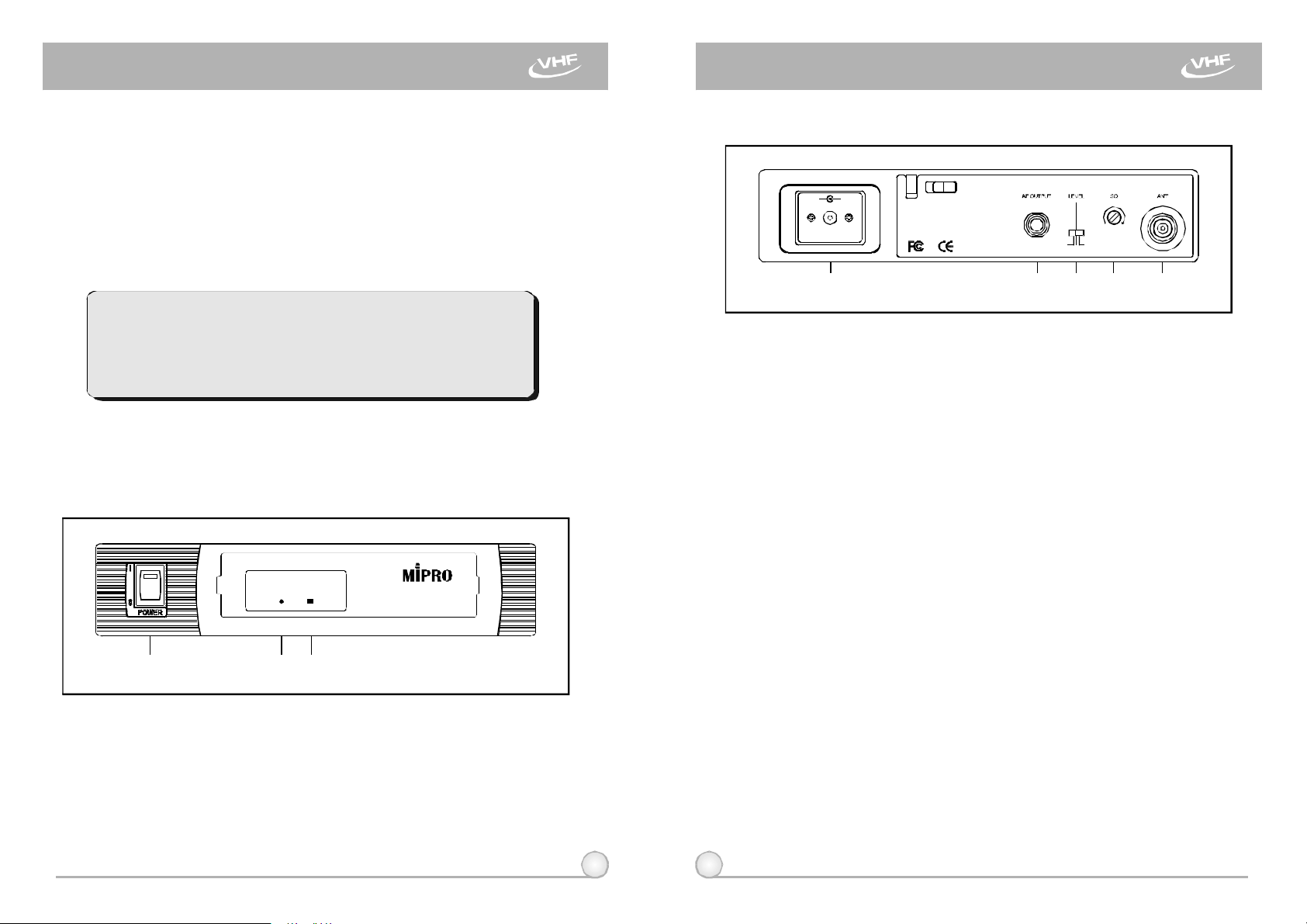
1.PARTSNAMEANDFUNCTIONS
A.FrontPanel
B.RearPanel
+
-
-6dB
+10dB
0dB
(8)(7)(6)(5)(4)
Fig.2
(5)DC12VInputJack:Toconnect12VDCfromtheAC/DCadapter.
(6)UnbalancedAudioOutputJack:With1/4PhoneJackprovidesaudio
λ
outputsignalfromthisjacktotheamplifier.
(7)UnbalancedLevelSwitch:"0dB"selectionisfor"Microphone-level"
output."+10dB"selectionisfor"AUXlevel"output.-6dBselection
〝〞
isforhalfofcablemicrophonevolume.
(8)SquelchAdjusters:AdjustthesquelchleveltoeliminatetheRFnoise
interferenceatreceiverstand-bystate.
(9)AntennaInputConnectors:ForrearAntennaPlacement.
SIGNAL
AFRF
(1) (2) (3)
MR-515 VHF
WIRELESSRECEIVER
Fig.1
(1)PowerSwitch&Indicator:Whenswitchisturnedon,redindicator
illuminatestodenotenormalpowerstatus.
(2)RFSignalIndicator:IndicatesreceivingtransmittingRFsignals.
(3)AudioSignalIndicator:Indicatesthemicrophonesignal.
1 2
Page 3
SINGLECHANNELWIRELESSRECEIVER SINGLECHANNELWIRELESSRECEIVER
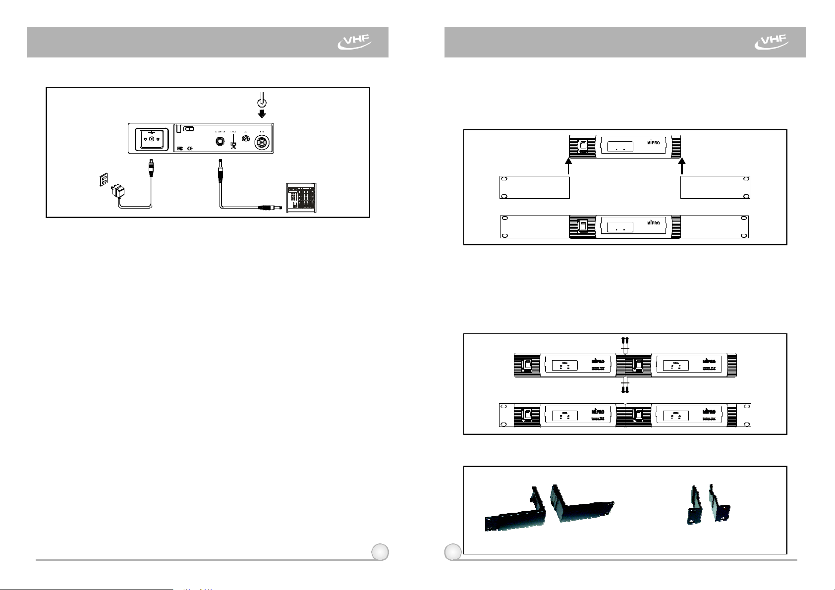
2.INSTALLATIONOFTHERECEIVER 3. TWO19/2-INCHUNITSRECEIVERINSTALLATION
1.Singlehalf-rackreceiver
(a)Pushtherackmountearoptionalaccessory(FB-11)upwards
+
-
+10dB-6dB
0dB
Fig.3
1.Installantennainrear(8).Extendantennatothefullestposition.seefig.
3.
2.ConnecttheAC/DCadaptercabletoDC12VINPUTJACK(4),thenplug
theadapterunitintoanappropriateACoutletwithcautiontothecorrect
voltageunderbothACoutletandadaptermarked,asshowninfig.3.
3.AudioOutputConnection:
(a)UnbalancedLevelSwitch(6)SettingPosition:Whenconnectingfrom
receiver'sunbalancedoutputtothe"AUX-IN"jackofamixeror
amplifieror"ElectricGuitar",switchtheLevelSwitch(6)to"+10dB"
position.Lowsensitivitymayoccurifswitchtothewronglevelposition.
Whenconnectingfromreceiver'sunbalancedoutputtothe"MIC-IN"
jackofamixeroramplifier;switchtheLevelSwitch(6)to"0dB"
position.Overloaddistortionmayoccurifswitchtothewronglevel
position.Whenusingelectricguitar,don'tuse"0dB"or"-6dB"position
asitmayhavegeneratedinsufficient level.Therearelotsofamplifiers
forKaraokemachineintoday'smarket,however,gainofamplifier's
"MICIN"isnotunified.Therefore,ifdistortionisencountered,please
switchtheLevelSwitch(6)to"-6dB"position.
(B)UnbalancedOutput:Usingaudiooutputcableattachedwith"PHONE
PLUG"type,connectoneandfromtheunbalancedoutputjack(5)of
thereceiver,andtheotherendtothe"AUX-IN"inputjackofthe
amplifier,asshowninFig.3.
(c)GuitarOutput:Usingaudiooutputcableattachedwith"PHONEPLUG"
type,plugoneendfromtheunbalance-mixedoutputjackofareceiver,
andtheotherendtotheinputjackofaguitaramplifier.Switchthe
LevelSwitch(6)to"+10dB"position.
3 4
2. Dualhalf-rackreceivers
3.Rack-mountkitAccessories:
untilitisfirmlyattachedtothereceiver.(fig.4)
SIGNAL
AFRF
MR-515 VHF
WIRELESSRECEIVER
SIGNAL
AFRF
MR-515 VHF
WIRELESSRECEIVER
(a)Positiontheconnectingplatesbetweenthetopandbottomof
thetworeceiversandtighten.(Fig.5)
(b)Afterjoiningthe2receiverstogether,pushtheoptional
accessoryrackmountears(FB-12)upwardsuntiltheyfirmly
attachedtothereceiver.(Fig.5)
FB-11 FB-12
Rackmountkitfits1half-rack
Rackmountkitfits2
1half-rack
or
half-rack
Fig.4
Fig.5
Page 4

SINGLECHANNELWIRELESSRECEIVER SINGLECHANNELWIRELESSRECEIVER
4.Makesurethesystemperformscorrectly,
pleaseplacethesystemawayfromnoise
sources.Placethereceiveratleast1
meterabovethegroundandawayfrom
noisesources.Placethemicrophoneat
least1meterawayfromthereceiving
antenna,asshowninFig.6.
Ground
Fig.6
5.Withtworackmountbracketsinstalled,
receivercanbemountedintoanEIA
standardrackmountcase,asshownin
Fig.7.Asanaccessory,youmay
purchasefromnearestdealerafront
antennakit,whichnotonlyallowseasy
frontantennainstallation,butalso
improvesefficiencyofsignalreception.
Fig.7
4.OPERATIONINSTRUCTIONS
1.Turnvolumecontrolsofthereceiverandmixerinusetoaminimumsetting
beforeturnonthemicrophonesortransmitters.Afterswitchesonthe
receiver,thepowerswitchredindicatorilluminatestodenotenormalpower
status.
3.Undernormalcircumstances,theSIGNALindicatorlightsupwhena
microphoneortransmitteristurnedonnearthereceivertoindicatethe
receiverisreadyfornormaloperation.Oncesoundstothemicrophoneand
theAUDIOLEDindicators(4)willglowaccordingtothestrengthofsound
level.IfnoLEDglowsornosoundoutputs,thesystemisnotfunction
properly,thusitmustbechecked.
4.ReceiverandAmplifierVolumeAdjustment:
(a)UnbalancedAudioOutput:Switchthelevelswitch(6)onthereceiver
rearpaneltotheleftposition"MIC",thenadjustvolumecontrolofthe
amplifierormixertoobtainanappropriatesoundlevelofthe
microphone.
(b)Toobtainsamesensitivityandvolumelevelofbothwiredandwireless
microphonesinamixeroramplifierthathasmorethan2microphone
inputsockets,onecanadjustthewiredmicrophonevolumecontrolin
themixeroramplifier.Afterreachingdesiredsoundlevel,connectto
theAFoutputsocketofreceiver.Pleasenotethattheunbalanced
volumeswitchonthebackofthereceivershouldswitchto"MIC"
position.
(c)Ifthereceiveroutputlevelisadjustedexcessively,itwillcausethe
saturationdistortionofthemixeroramplifierwhenthemicrophoneis
loud.
+
-
+10dB-6dB
0dB
Fig.8
2.IfSIGNALLEDindicators(3)ofthereceiverlightonbeforeswitchesonthe
microphoneortransmitter,itindicatesthereceiverisreceivinginterference
signals.ThissystemhasPitlotoneandNoiseLockdual-squelchfeatures
andnonoiseoutputwilloccur.Ifmultiplechannelsareusedandboth
SIGNALandAUDIOLEDsglowandinterferencenoiseappear,simply
adjusttheSquelchcontrols(7)clockwiseuntilAUDIOsignalindicatorsto
extinguish.(Fig.8).However,byadjustingthesquelchcontrols,itaffects
thesensitivitylevelofthereceiver,therefore,shortentheoperatingdistance
anddecreasesthestability.
5 6
Page 5

SINGLECHANNELWIRELESSRECEIVER
HANDHELDWIRELESSMICROPHONE
5.Plugthecableofthemainsunitintodcsocketonthereceiver'sbackpanel.
Threadthecablethroughthecablegripasshownontheaboveillustration.
Thecablegrippreventstheconnectorfrombeingpulledoffbyaccident.
Fig.9
5.CAUTION
1.Sincetheinstallationofantennainfluencestheoperatingefficiencyofthe
receiver,themostimportantruleistominimizedthedistancebetween
receivingantennaandmicrophoneasshortaspossibleforbetterreception
andperformance.
2.TheexternalDCpowersupplyshouldnotbebelow12V,otherwiseitwould
notworkproperly.Ifitisover15V,somecomponentsofthereceiverwillbe
damaged.
3.Whenusingmulti-channelsystemssimultaneously,properchannel
frequencyselectionisveryimportanttoavoidmutualinterference.
7
Latestmodularizedmicrophonestructure.Built-in"Piltone&NoiseLock"
dual-squelchcircuitryeliminates"pop"interference.
1 2 3 4
5
6 7
(Fig.1)
1.PARTSNAMESANDFUNCTIONS
1.Grille:Protectscartridgeandprevents"POP"noise.
2.BatteryStatusIndicator:Indicatespoweron/offandthebatterystatus.
WhenthepowerswitchisturnedON,theredLEDsindicatorflashesbriefly,
indicatingnormalbatterystatus.Ifnoflashoccurs,itmeanseitherno
batterypowerorthebatteryisdischargedorinstalledincorrectly.Ifthe
indicatorstayslitafterpoweringon,itwarnsthebatterypowerislowand
shouldbereplaced.
PUSHKNOBUPWARDTOTURNONANDDOWNWARDTOTURNOFF
TRANSMITTER.
3.PowerOn-offSwitch:Slidetheswitchforpower"ON"or"OFF".
4.Housing:Upperportionisconnectedtocapsulemoduleandbattery.
Internally,itholdstransmitterPCB.
5.BatteryCompartment:Designedtoaccommodateone9Vbattery.
6.BatteryCap:Coversthebatterycompartment.
7.Anti-rollRing:Forfrequencydifferentiation.
8
Page 6
BODYPACKTRANSMITTER BODYPACKTRANSMITTER
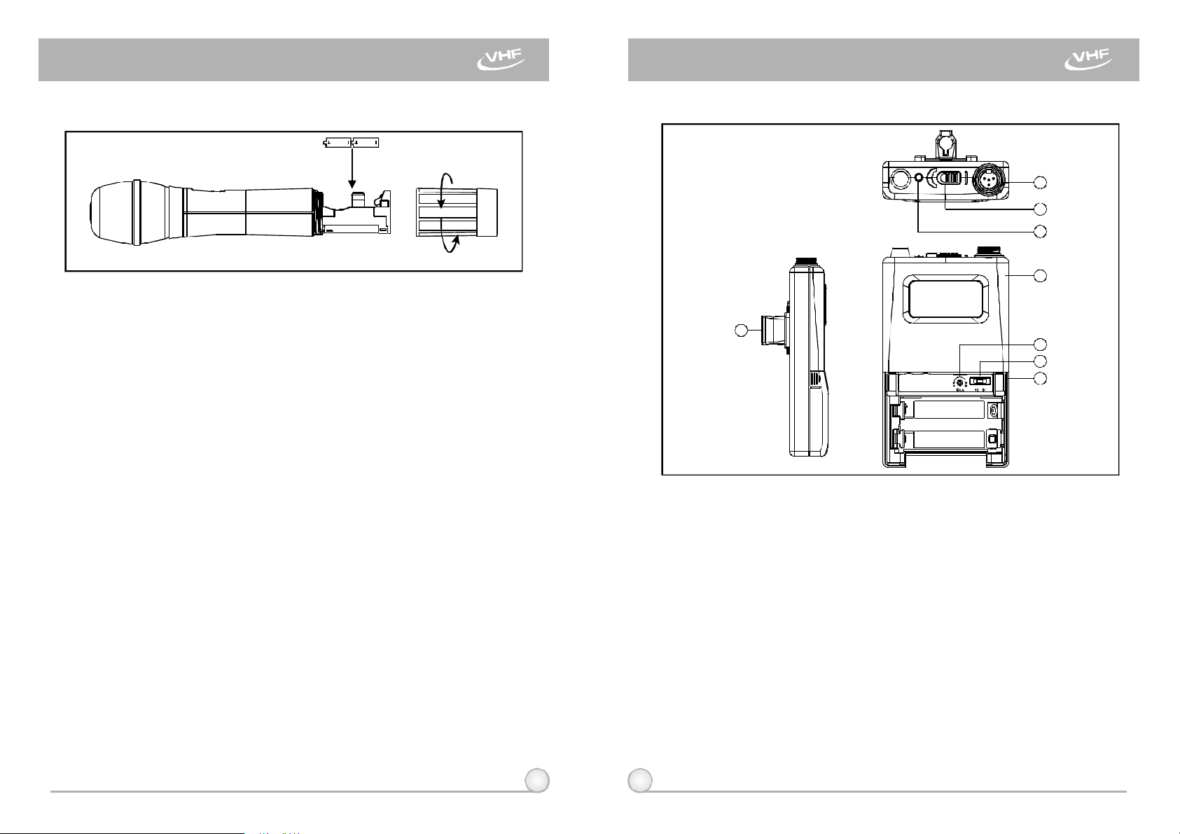
2.BATTERYINSERTION
(Fig.2)
1.Unscrewbatterycap(6)inacounter-clockwisedirection.
2.Insertwo1.5V(AA)batteryintothebatterycompartmentobservingthe
correctpolarity.Themomentthebatterytouchestheterminalsofthe
compartment,theindicatorwillflashbriefly.Thismeansthepolarityis
correct.However,ifnoflashoccurs,thisindicateswronginsertionor
batteryisdead.Pleasere-insertthebatteryobservingitscorrectpolarityor
changetoafreshbattery.
3.OPERATINGINSTRUCTIONS
1.Whenmicrophoneisswitchedon:
Atthemomentofthepowerisswitchedon,theindicatorwillflashbriefly
indicatingnormaloperation.
(a)Whenpoweron:
SIGNALLEDindicatorofreceiverglows.
(b)Afterpoweron:
MoreLEDindicatorsshowsreceivedsignalstrengthisstrong.
(c)DuringUsage:
AUDIOLEDdisplaysreceivedAFlevelfromthemicrophone.
(d)Whenthemicrophoneisnotinuse:
Makesurethepowerofthemicrophoneisoff.Ifthemicrophonewill
notbeusedforsometime,pleaseremovethebatteriesfromthe
batterycompartmenttoavoidbatteryleakageandresultindamaged
batteryspringsandcircuit.Ifarechargeablebatterywasused,takeit
outandrechargeit.
1.PARTSNAMESANDFUNCTIONS
1
2
3
4
8
5
6
7
(Fig.1)
1.AFInputJack:Connectstoalavaliereorheadsetmicrophone.(See5ways
ofconnectiononAFInputConnections)
2.PowerSwitch:SwitchtoONpositionforoperation.SwitchtoOFFposition
whennotinuse.
3.BatteryStatusIndicator:Indicatesthepoweron/offandbatterystatus.
(a)Whenpowerswitchisturnedon:TheLEDindicatorflashesbriefly,
indicatingnormalbatterystatus.
(b)WhenREDlightilluminatesateitherpoweronorduringusage:The
batterylevelislow,therefore,anewbatteryreplacementisthusnecessary.
4.TransmitterHousing:PackagesthePCBandbattery.
5.GainControl:Adjuststhedesirousinputgain.
6.GT/MTLevelSelector:SwitchGTpositionforelectricguitarusageONLY.
GainControlisirrelevantfor"GT".Switchto"MT"forcondenser
microphone,wiredmicrophone.GainControlworksin"MT"forinput
sensitivityadjusting.
7.BatteryCompartmentandCover:Accommodatestwo1.5V(AA)batteries.
9
10
Page 7
BODYPACKTRANSMITTER BODYPACKTRANSMITTER
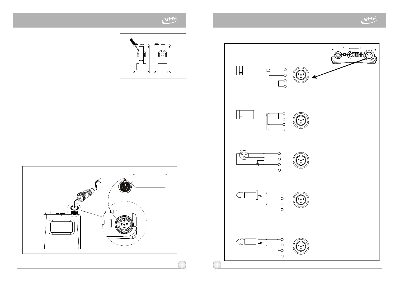
8.DetachableBeltClip:Allows360degrees
rotatingtosuittransmittingangles.To
detachsimplyuseascrewdriverata45
degreeangletounfasten.seediagram.
(Fig.2)
2.OPERATINGINSTRUCTIONS
1.Toadjustvolume(5),GT/MTSwitch(6),simplypushdownbothsnap
locksonthesidesofbatterycoverandflipitbackwardstoexposethe
adjustmentpanel.
2.TheLEDindicatorflashesbrieflywhenpoweronindicatingnormalbattery
status.Ifnoflashoccursithaseithernobattery,thebatteryisdrainedor
installedincorrectly.Changeaccordingly.
3.AdjustGainControltodesiredvolume.(GainControlisirrelevantwhen
switchtoGTposition).
4.Plugthemicrophoneconnectorintotheinputjack(1)andtightenthe
connectorscrewbyclockwisedirectionasshownin(Fig.3).
CapsuleConnector
Headset
Lavalier
Theridgeonthe
connectormustmatchthe
indentationonthesocket
wheninserting.”
3.AF4-PININPUTCONNECTIONMETHODS
(1)2-WireElectretCondenserMicrophoneCapsule
PIN
SHIELD
AUDIO
(2)3-WireElectretCondenserMicrophoneCapsule
SHIELD
AUDIO
BIAS
(3)DynamicMicrophone
2 1
3
SHIELD
AUDIO
(4)ElectricGuitar
SHIELD
AUDIO
PIN
PIN
1
4
1
2
3
4
PIN
1
2
3
4
1
2
3
4
1
2
3
4
1 3
1 3
1 3
3
2
4
2
4
2
4
2
4
1
LOW
3
2
OFF ON BATT.
(Fig.3)
11 12
(5)Line-in(Impedance8KATT.10dB)Ω
PIN
SHIELD
AUDIO
1
2
3
4
4
1
3
2
(Fig.4)
Page 8
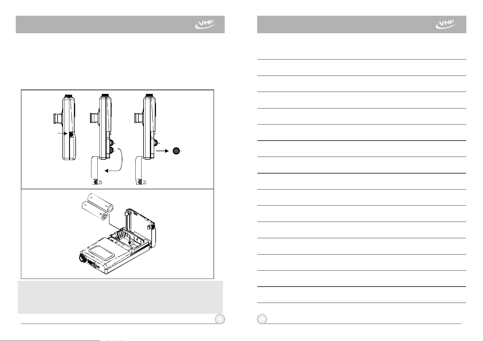
4.BATTERYINSTALLATION
1.Pushingdownbothsnaplocksonthesidesofbatterycovertoopenbattery
cover.Takeoutthebatteries.Fig.5).
2.Insertatwo1.5(AA)batteriesintothebatterycompartmentaccordingtothe
correctpolarityasshowninFig.5).Thenpushuptoclosethebattery
compartmentasshowninFig.6).
(Fig.5)
NOTEBODYPACKTRANSMITTER
PS:Whenthemicrophoneisnotinuse:
Makesurethepowerofthemicrophoneisoff.Ifthemicrophonewillnotbe
usedforsometime,pleaseremovethebatteriesfromthebatterycompartment
toavoidbatteryleakageandresultindamagedbatteryspringsandcircuit.Ifa
rechargeablebatterywasused,takeitoutandrechargeit.
(Fig.6)
13 14
Page 9

NOTENOTE
15 16
 Loading...