

Page 1
2 CE 4 4 5 A
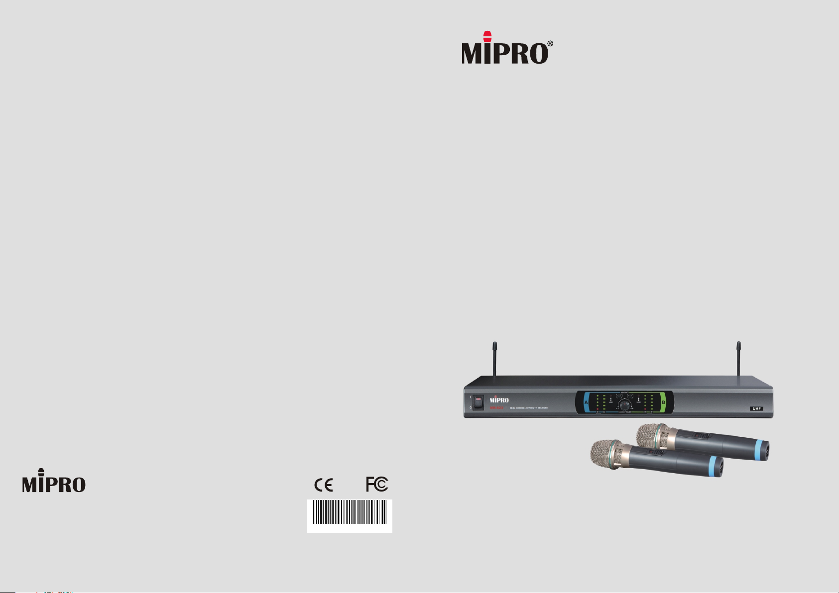
MR-823 / MH-80 /MT-801a
UHF Dual-Channel Diversity Wireless Microphone System
User Guide
MIPRO Electronics Co., Ltd.
Headquarters: 814 Pei-Kang Road, Chiayi, 60096, Taiwan.
Web: www.mipro.com.tw
E-mail: [email protected]
Design and specifications are subject to change without prior notice
AS121201
Page 2
! IMPORTANT SAFETY INSTRUCTIONS !
WARNING
1. Read these instructions.
2. Keep these instructions.
3. Heed all warnings.
4. Follow all instructions.
5. Do not use this apparatus near water.
6. Clean only with a dry cloth.
7. Do not block any ventilation openings. Install in accordance with the
manufacturer's instructions.
8. Do not install near any heat sources such as radiators, heat registers,
stoves, or other apparatus (including amplifiers) that produce heat.
9. Do not defeat the safety purpose of the polarised or ground plug: A
polarised plug has two blades with one wider than the other. The wide blade
is provided for your safety. When the provided plug does not fit into your
outlet, consult an electrician for replacement of the obsolete outlet.
10. Protect the power cord from being walked on or pinched particularly at plug,
convenience receptacles, and the point where they exit from the apparatus.
11. Only use attachments/accessories specified by the manufacturer.
12. Use only with a cart, stand, tripod, bracket, or table specified
by the manufacturer, or sold with the apparatus. When a cart
is used, use caution when moving the cart/apparatus
combination to avoid injury from tip-over.
13. Unplug this apparatus during lightning storms or when unused
for long periods of time.
14. Refer all servicing to qualified service personnel. Servicing is required
when the apparatus has been damaged in any way, such as power-supply
cord or plug is damaged, liquid has been spilled or objects have fallen into
the apparatus, the apparatus has been exposed to rain or moisture, does not
operate normally, or has been dropped.
15. To reduce the risk of fire or electric shock, do not expose this apparatus to
rain or moisture.
16. Apparatus should not be exposed to dripping or splashing and no objects
filled with liquids, should be placed on the apparatus.
17. Use only with the battery which specified by manufacturer.
18. The power supply cord set is to be the main disconnected device.
1. FOR OUTDOOR USE:
To reduce the risk of fire or electric shock, do not expose this apparatus to
rain or moisture.
2. UNDER WET LOCATION:
Apparatus should not be exposed to dripping or splashing and no objects
filled with liquids, such as vases should be placed on the apparatus.
3. SERVICE INSTRUCTIONS:
CAUTION - These servicing instructions are for use by qualified service
personnel only. To reduce the risk of electric shock, do not perform any
servicing other than that contained in the operating instructions unless you
are qualified to do so.
This symbol indicates that dangerous voltage constituting a risk of
electric shock is present within this unit.
This symbol indicates that there are important operating and
maintenance instructions in the literature accompanying this unit.
& IC - ID
THIS DEVICE COMPLIES WITH PART 15 OF THE FCC RULES AND RSS-123 ISSUE2 OF
CANADA. OPERATION IS SUBJECT TO THE FOLLOWING TWO CONDITIONS:
(1) This device may not cause interference.
(2) This device must accept any interference, including interference that may cause
undesired operation of the device. This equipment complies with FCC RF radiation
exposure limits set forth for an uncontrolled environment.
Disposal
200 5-08- 13200 5-08- 13
Dispose of any unusable devices or batteries responsibly and in accordance
with any applicable regulations.
Disposing of used batteries with domestic waste is to be avoided!
Batteries / NiCad cells often contain heavy metals such as cadmium(Cd),
mercury(Hg) and lead(Pb) that makes them unsuitable for disposal with
domestic waste. You may return spent batteries/ accumulators free of
charge to recycling centres or anywhere else batteries/accumulators are
sold.
By doing so, you contribute to the conservation of our environment!
Page 3
Contents
UHF Dual-Channel Diversity Receiver
UHF DUAL-CHANNEL DIVERSITY RECEIVER PRODUCT OVERVIEW
PRODUCT OVERVIEW
KEY FEATURES AND BENEFITS
PART NAMES AND FUNCTIONS
RECEIVER INSTALLATION
TIPS FOR ACHIEVING OPTIMUM PERFORMANCE
CAUTION
1
1
2
4
7
7
Thank you for choosing MIPRO wireless microphone system. Please read this user guide
thoroughly to ensure the system is operated correctly to maintain optimal performance.
It features diversity technology for reliable reception, warning indicator for presence of
interference and dual "Pilotone & NoiseLock" controlled squelch to deter unwanted signals
and random noise interference sources such as computers, karaoke machines and DVD
players.
Our professional wireless microphone systems deliver transparent sound quality, reliable
RF performance and unrivaled innovative features. This system offers the finest
components, engineering technology and styling, just what you would expect from MIPRO.
HANDHELD WIRELESS MICROPHONE
PART NAMES AND FUNCTIONS
TRANSMITTER BATTERY INSERTION
OPERATING INSTRUCTIONS
BODYPACK TRANSMITTER
PART NAMES AND FUNCTIONS
OPERATING INSTRUCTIONS
AF 4-PIN INPUT CONNECTION METHODS
TRANSMITTER BATTERY INSTALLATION
OPTIONAL ACCESSORIES
9
10
11
12
14
15
16
17
KEY FEATURES AND BENEFITS
EIA standard 19”1-rack unit design.
!
Dual fixed-frequency design receiver.
!
Operates on the less-crowded UHF bandwidth.
!
Diversity technology ensures reliable transmission quality.PLL-synthesized design
!
provides excellent frequency stability and simultaneous multi-channel operation.
5-segment RF and Audio level meters.
!
Dual "Pilotone & NoiseLock" squelch prevent random noise interference sources like
!
computers, karaoke machines and DVD players.
Antennas can be mounted on either the front or rear panel to provide flexibility.
!
Balanced XLR and unbalanced 1/4" audio outputs.
!
First wireless receiver equipped with a "receiving sensitivity adjustor" and "NOISE" LED
!
indicator. Allows users to identify the presence of interference and able to adjust for the
ideal sensitivity level to overcome the interference.
First receiver equipped with a balanced volume control to enable users to adjust the
!
mixed output volume of two wireless microphones.
The system's default output level is accurately pre-adjusted to match the microphone
!
capsule sensitivity. Therefore, users don't need to adjust the volume of the receiver.
The user can operate the system easily, as if it were a wired microphone.
Ideal for small to medium sized stages, PA and karaoke venues.
!
The System Includes the Following Accessories:
Receiver ×1
Audio Output Cable ×2
Antenna ×2
AC/DC Adapter ×1
User Guide ×1
0
1
Page 4
UHF Dual-Channel Diversity ReceiverUHF Dual-Channel Diversity Receiver
PART NAMES AND FUNCTIONS
Front Panel: Rear Panel:
4 5 9 10
SENSITIVITY
NOISE
NOISE
MR-823
1
1
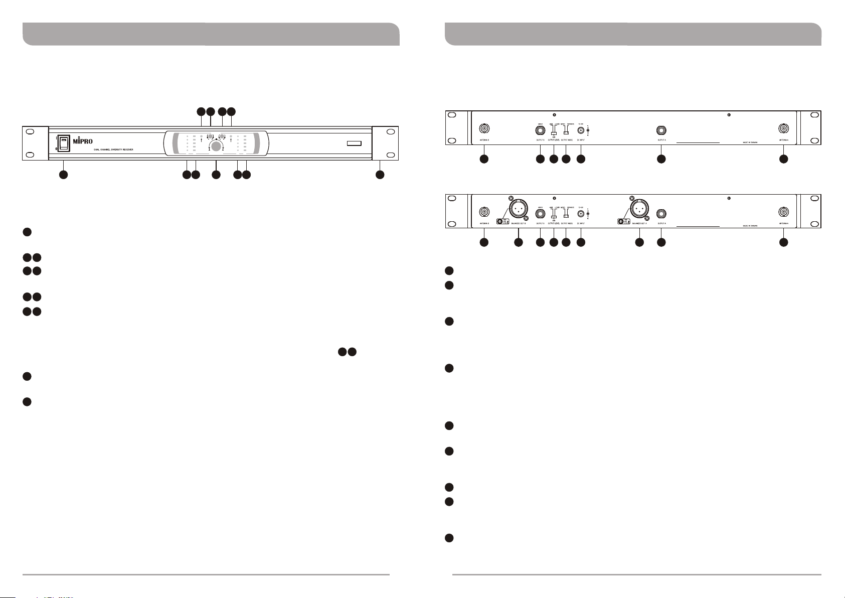
Power On/Off Switch & Indicator: Turns the receiver on and off. Red light glows
A B
RF AF RF AF
A
BALANCE VOLUME
32 876
B
when the switch is pressed. It denotes the receiver is on.
2
7
RF Level Indicators: Indicates received RF (Radio Frequency) signal strength.
3
8
Audio Level Indicators: Indicates transmitted audio signal strength from the
transmitters.
4
10
Noise Warning Indicator: Red light glows denoting the presence of interference.
5
9
Sensitivity Control: This control affects the operating range and signal quality. It
is factory pre-set at “+” position and no further adjustment is normally required.
+: (Default) High sensitivity and longest operating range.
-: Adjust counterclockwise accordingly when Noise Warning Indicator glows to
minimize interferences. However, such action decreases operating range.
6
Microphone Balance Volume Control: Allow users to adjust the mixed volume
level of two transmitters to a balanced or different level.
11
Rackmount Brackets (Optional): Allows the installation of the receiver into an
EIA-standard 19" rack.
UHF
4 10
811
(Figure 1)
12 13 14 15 16 17 18
12 19 13 14 15 16 20 17
12
Antenna B Input Connector: To install TNC-type Antenna.
13
Unbalanced Audio Output Connector B (High Z / AF out): This 1/4”(6.35mm)
phone jack provides an unbalanced high impedance line level output. An unbalanced
audio cable phone plug can be used between this connector and amplifier input.
14
Unbalanced Level Switch:
0dB selection is for microphone-level output.
+10dB selection is for auxiliary level output.
-6dB selection is for half of cable microphone volume.
15
Unbalanced Mixed Switch:
MIXED - Audio signal from both Channel A & B will be mixed into Output B and no
audio output from Output A.
SEPARATE - Audio signal will be transmitted separately from Output A and Output
B.
16
Power Input Connector: Connect a 12 volt AC/DC power adapter to this jack and
then plug into an AC outlet.
17
Unbalanced Audio Output Connector A (High Z / AF out): This 1/4”(6.35mm)
phone jack provides an unbalanced high impedance line level output. An unbalanced
audio cable phone plug can be used between this connector and amplifier input.
18
Antenna A Input Connector: To install TNC-type Antenna.
19
Balanced Audio Output Connector B (Low Z / AF out): XLR connector provides
a balanced low impedance microphone-level output. Plug an XLR audio cable from
this connector to the input of a mixer. (Optional)
20
Balanced Audio Output Connector A (Low Z / AF out): XLR connector provides
a balanced low impedance microphone-level output. Plug an XLR audio cable from
this connector to the input of a mixer. (Optional)
2
3
18
(Figure 2)
Page 5
UHF Dual-Channel Diversity ReceiverUHF Dual-Channel Diversity Receiver
RECEIVER INSTALLATION
12
19 13131414151516
12
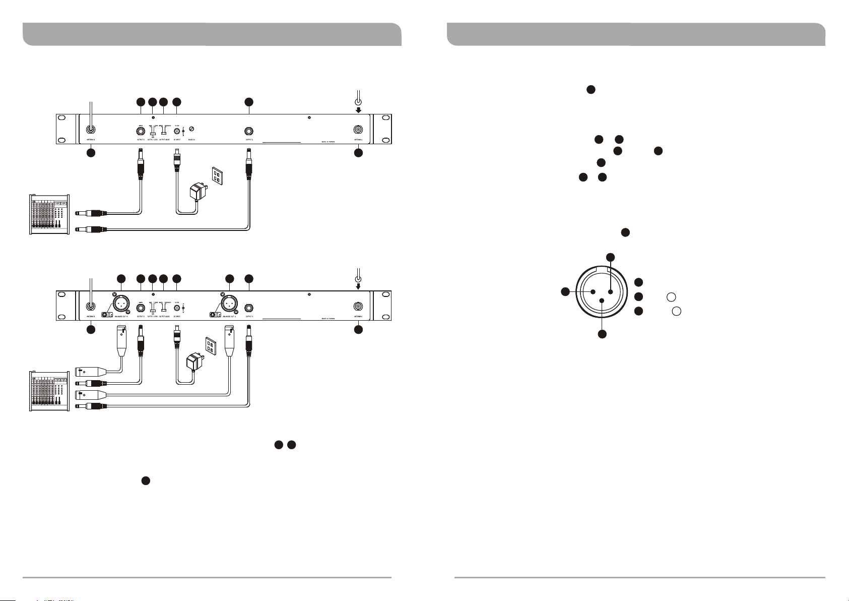
3. AUDIO OUTPUT CONNECTION:
Unbalanced Level Switch :
!
16
17
0dB: Microphone input of a mixer or amplifier
!
+10dB: Electronic guitar/bass.
!
-6dB: If audio is distorted due to high vocal or instrument levels.
Unbalanced Audio Outputs , :
!
18
SEPARATE: From output jack B and A .
!
MIXED: From output jack B only.
Balanced Audio Output , : Plug an XLR audio cable from this connector to
14
1713
13
13
20
19
17
the input of a mixer.
(The characteristic of the 3-pin connector is as shown in figure 5)
Electric Guitar/Bass Output:
14
2
1
GND
2
HOT
+
3
-
COLD
3
(Figure 5)
20 17
(Figure 3)
18
Switch the Unbalanced Level Switch to "+10dB" position.
1
(Figure 4)
18
1. Install the 2 antennas to the antenna input connectors on the rear panel
12
illustrated in Figure 3 & 4.
2. Connecting the power supply: Connect the AC/DC adapter cable to the DC 12V
Power Input Connector illustrated in Figure 3 & 4. Next plug the adapter unit into
16
an appropriate AC outlet with caution to the correct voltage for both AC outlet and
adapter as marked.
4
5
Page 6
UHF Dual-Channel Diversity ReceiverUHF Dual-Channel Diversity Receiver
4. Place the receiver away from noise sources like computers, cordless phones, metal
objects or other RF generating equipment such as CD players, DAT machines, and
digital signal processors.
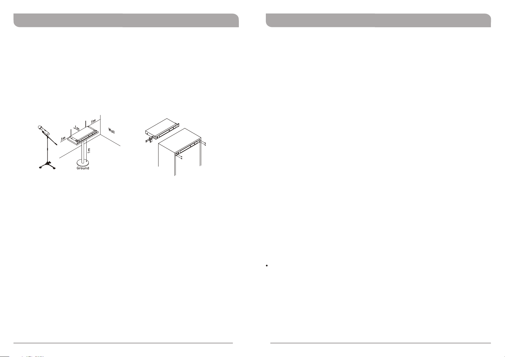
5. To ensure best possible reception, the receiver must be installed at least 1 meter
(3.3 feet) above the ground. In addition, the distance between the transmitter and
receiver must be more than 1 meter (3.3 feet) as illustrated in Figure 6.
6. Mount the receiver(s) into an EIA-standard 19" rack as illustrated in Figure 7. To
improve antenna reception, an optional pair of FB-30, front mount antenna kit, can
be installed in the front panel.
(Figure 6) (Figure 7)
TIPS FOR ACHIEVING OPTIMUM PERFORMANCE
! Maintain a line-of-sight between transmitter and receiver antenna. Metal objects
between the transmitter and receiver will usually greatly reduce range.
! Minimize the distance between transmitter and receiver as much as possible for optimal
reception and performance and reduce the chances of signal drop-outs.
! Mount the receiver position in a standard 19” rack as high as possible.
! Mount receiver antennas as high as feasible above the floor or stage.
! Avoid placing transmitter and receiver where metal or other dense materials may be
present.
! Use the supplied receiver antenna.
! Do not obstruct receiver antenna.
! Always operate any wireless microphone system with its antennas fully extended.
! Do not allow receiver antennas to touch each other.
! Perform a walk-through before your performance or presentation. If dead spots are
found, try moving the receiver a meter or so. If dead spots remain, simply mark these
spots and avoid them.
! Use only fresh alkaline batteries for optimal battery hours and performance. Other
types of batteries might have too low a voltage or inadequate capacity for the
transmitter to achieve full power output.
! The receiver cannot pick up signals from two transmitters at the same time.
! Turn transmitter off when not in use to conserve battery power. Always remove the
battery if the transmitter is not to be used for a period of longer than one week. If a
battery is left in, it may leak battery acid and damage the internal electronics.
CAUTION
The output voltage of the external DC power supply should not be below 12V, otherwise
it will not work properly. If the voltage is over 15V some components of the receiver
will be damaged due to excessive current draw.
6
7
Page 7
Handheld Wireless Microphone
PART NAMES AND FUNCTIONS
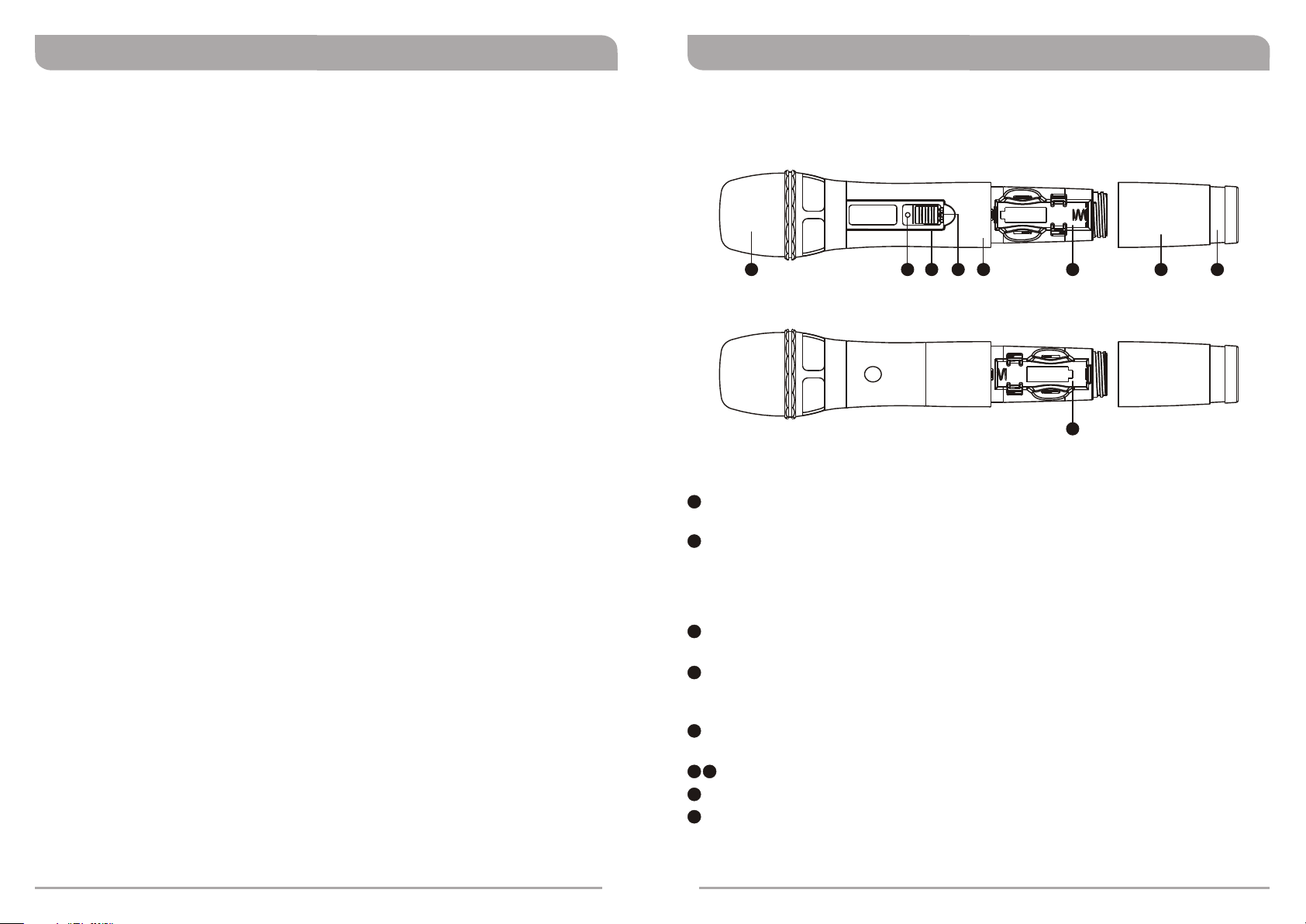
222923 24 25
26
27 2821
(Figure 8)
21
Top Grille: Protects detachable microphone capsule module and internal foam
prevents breathing, wind and POP noises.
22
Battery Status Indicator: Indicates power on / off and the battery status.
!
Normal Battery Red indicator glows briefly and dims.
!
Low Battery Red indicator glows. Replace batteries.
Drained Battery Red indicator does not glow. Replace batteries.
!
23
Power On/Off Switch: Slide the power switch to the “ON” position for use or to the
“OFF” position when not in use.
24
Lockable On/Off Switch: Slide the switch to the “ON” position after power-on to
avoid accidental power off during performance. Slide the switch to “OFF” position
before power-off and conserve battery power.
25
Housing: Upper portion connects to the microphone capsule module. Internally it
holds the transmitter PCB and battery compartment.
26 29
Battery Compartment: Accommodates 2 AA alkaline.
27
Battery Compartment Cover: Protects battery compartment and holds batteries.
28
Color-Coded Ring: Available in different colors for channel differentiation.
8
9
Page 8
Handheld Wireless Microphone Handheld Wireless Microphone
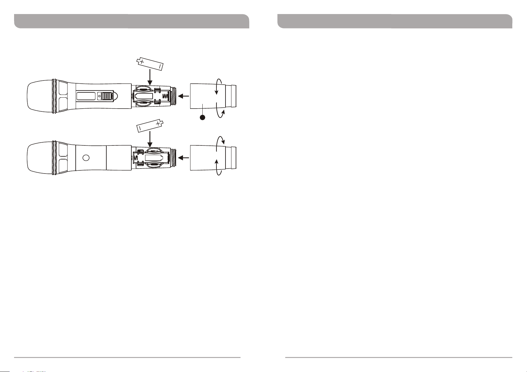
TRANSMITTER BATTERY INSERTION
27
(Figure 9)
1. Gently twist the microphone housing in a counter-clockwise direction.
2. Remove the old batteries from the battery compartment, if any are installed.
3. Insert two new AA alkaline batteries in the battery compartment with correct polarity
orientation. If normal, the red LED indicator will light solid for a second after the
transmitter is turned-on. Fasten the microphone housing when done.
4. In the case of low battery, the red LED indicator will stay illuminated. Change to new
fresh batteries.
5. In the case of dead battery, the red LED indictor will not be illuminated.
OPERATING INSTRUCTIONS
1. The red LED indicator will light solid for a second and the RF level/indicator shown on
the receiver will remain illuminated after the transmitter is turned-on, denoting normal
status. No illumination in the red LED indicates an incorrect battery polarity insertion,
dead batteries or malfunction.
2. The audio level or indicator show on the receiver will be lit when there is audio line or
microphone input from the transmitter.
CAUTION
Remove the batteries if unused for a long period of time to prevent battery leakage,
corrosion and causes damage to electronics.
10
11
Page 9
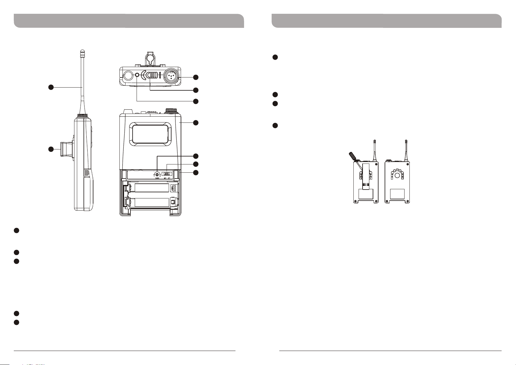
PART NAMES AND FUNCTIONS
38
37
Bodypack Transmitter Bodypack Transmitter
35
GT/MT Level Selector: Guitar/Microphone Selector.
GT- For electric guitar/bass instrument cable. Gain Control is irrelevant for “GT”
30
31
32
33
34
35
36
mode.
MT- For a variety of lavaliere and headworn microphone cables. Gain Control works
in the “MT” mode for input sensitivity adjustments
36
Battery Compartment: Holds 2 “AA” (1.5V) batteries.
37
Detachable Belt Clip: Allows the transmitter to be worn on a belt, waistband or
guitar strap for a 360 degrees rotating. To detach simply use a screwdriver at a 45
degree angle to unfasten. See Figure 11.
38
Transmitting Antenna: 1/ 4 wavelength transmitting antenna.
(Figure 10)
30
4-Pin AF Jack Input Connector: Connects to the MIPRO TA4F XLR connector. For
lavaliere, headworn microphone or instrument cable. (See 5 methods of AF Input
Connections in Figure 13)
31
Power On/Off Switch: Turns the transmitter on and off.
32
Battery Status Indicator: Indicates power on / off and the battery status.
When the Power On/Off Switch is turned on:
! Normal Battery Red indicator glows briefly and dims.
! Low Battery Red indicator glows. Replace batteries.
! Drained Battery Red indicator does not glow. Replace batteries.
! Battery not properly Installed Red indicator does not glow.
33
Housing: Holds the transmitter PCB and battery compartment.
34
Gain Control: Adjusts the input gain to an appropriate level.
12
(Figure 11)
13
Page 10
Bodypack Transmitter Bodypack Transmitter
OPERATING INSTRUCTIONS
1. Turn the transmitter on.
2. With a normal battery, the red indicator glows briefly and dims when the transmitter
is turned on. See Battery Status Indicator for other indications.
3. When the performance is over, turn off the transmitter to conserve battery power.
! Select GT/MT Switch :
GT- For electric guitar/bass instrument cable. Gain Control is irrelevant for “GT”
mode.
MT- For a variety of lavaliere and headworn microphone cables. Gain Control works
in the “MT” mode for input sensitivity adjustments.
! Gain Control : Volume can be adjusted by the gain control. Gain Control is
34
irrelevant when switch to GT position.
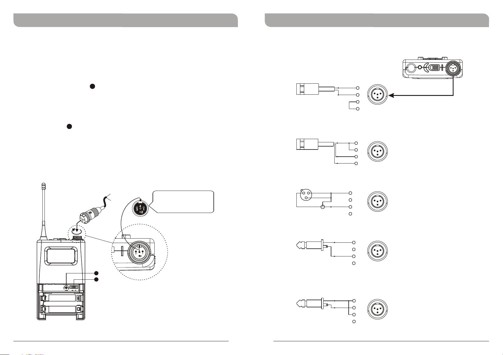
! 4-Pin Connector: Before making these connections turn off the transmitter to
prevent damage to transmitter, receiver or speaker system. Align and insert the 4pin plug into the connector accordingly and tighten in a clockwise direction
illustrated in Figure 12. When done, turn the transmitter on.
35
Capsule Connector
Headset
Lavalier
The ridge on the
connector must match
the indentation on the
socket when inserting.
AF 4-PIN INPUT CONNECTION METHODS
2-Wire Electret Condenser Microphone Capsule
PIN
SHIELD
AUDIO
3-Wire Electret Condenser Microphone Capsule
SHIELD
AUDIO
BIAS
Dynamic Microphone
2 1
3
SHIELD
AUDIO
PIN
1
4
1
2
3
4
PIN
1
2
3
4
1
2
3
4
3
2
4
1
3
2
4
1
3
2
(Figure 13)
Electric Guitar
PIN
SHIELD
AUDIO
34
35
1
2
3
4
4
1
3
2
Line-in (impedance 8KΩ attenuation 10dB)
PIN
(Figure 12)
14
15
SHIELD
AUDIO
1
2
3
4
4
1
3
2
Page 11
Bodypack Transmitter
Optional
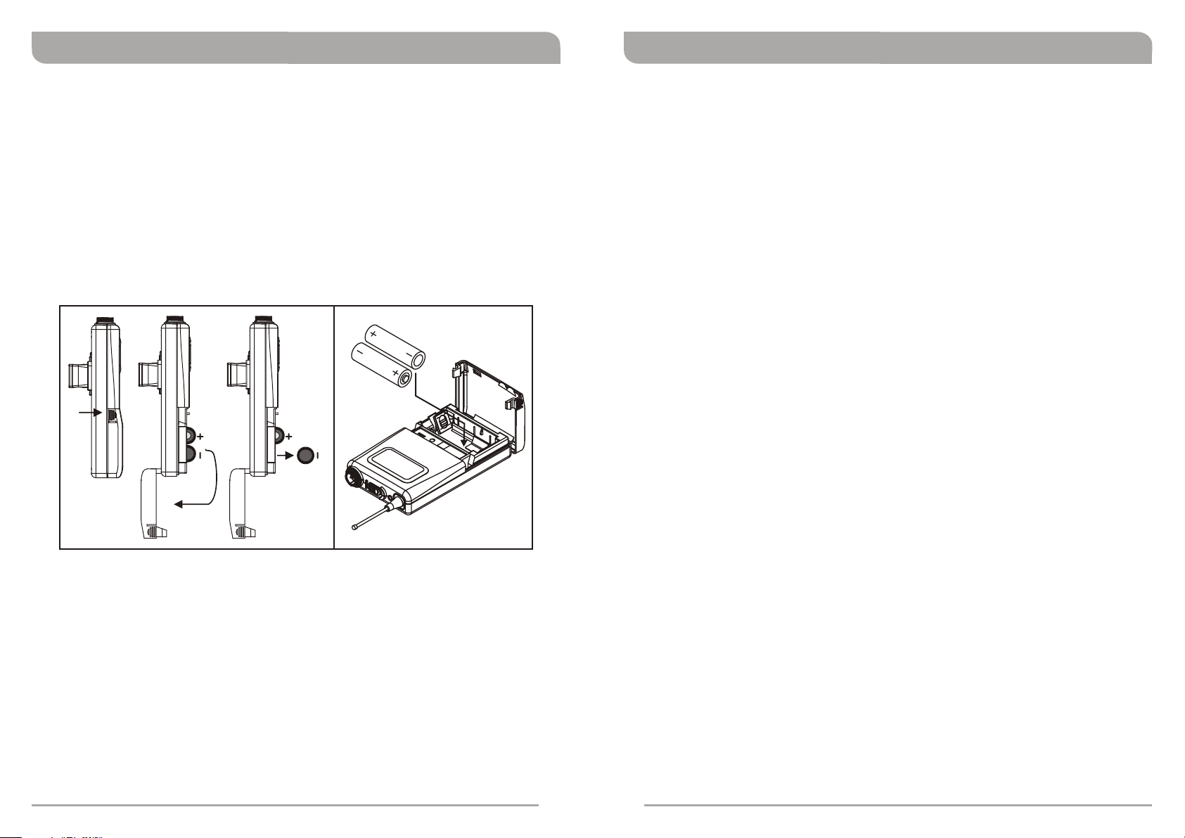
TRANSMITTER BATTERY INSTALLATION
1. Turn the transmitter off.
2. Push in with your thumb and index fingers on both battery cover snap locks to open
battery compartment cover as illustrated in Figure 14.
3. Insert 2 “AA” batteries into the battery compartment observing the correct polarity.
The moment the battery touches the terminals of the compartment, the indicator will
flash briefly. This means the polarity is correct. However, if no flash occurs, this
indicates wrong insertion or battery is dead. Please re-insert the battery observing its
correct polarity or change to fresh batteries. Figure 15.
4. Replace battery compartment cover
OPTIONAL ACCESSORIES
FB-12: Rack-mount brackets fit into a standard 19” rack.
FB-30: Front mount Antenna Kit. Allow rear-to-front antenna installation.
(Figure 14) (Figure 15)
NOTE
- Alkaline batteries are recommended. Always replace both batteries at the same time;
don't mix old and new batteries or different battery types and makes together.
- Remove batteries when not in use for an extended period of time to prevent battery
leakage which may cause potential damage to PCB board.
16
17
 Loading...