

Page 1
& IC - ID
2CE390B
THIS DEVICE COMPLIES WITH PART 74 OF THE FCC RULES AND RSS123 ISSUE1 OF CANADA. OPERATION IS SUBJECT TO THE
FOLLOWING TWO CONDITIONS:
(1) This device may not cause interference.
(2) This device must accept any interference, including interference
that may cause undesired operation of the device. This equipment
complies with FCC RF radiation exposure limits set forth for an
uncontrolled environment.
Disposal
Dispose of any unusable devices or batteries
responsibly and in accordance with any applicable
regulations.
Disposing of used batteries with domestic waste is to
2005 -08-1 32005 -08-1 3
be avoided!
Batteries / NiCad cells often contain heavy metals
such as cadmium(Cd), mercury(Hg) and lead(Pb) that
makes them unsuitable for disposal with domestic
waste. You may return spent batteries/ accumulators
free of charge to recycling centres or anywhere else
batteries/accumulators are sold.
By doing so, you contribute to the conservation of
our environment!
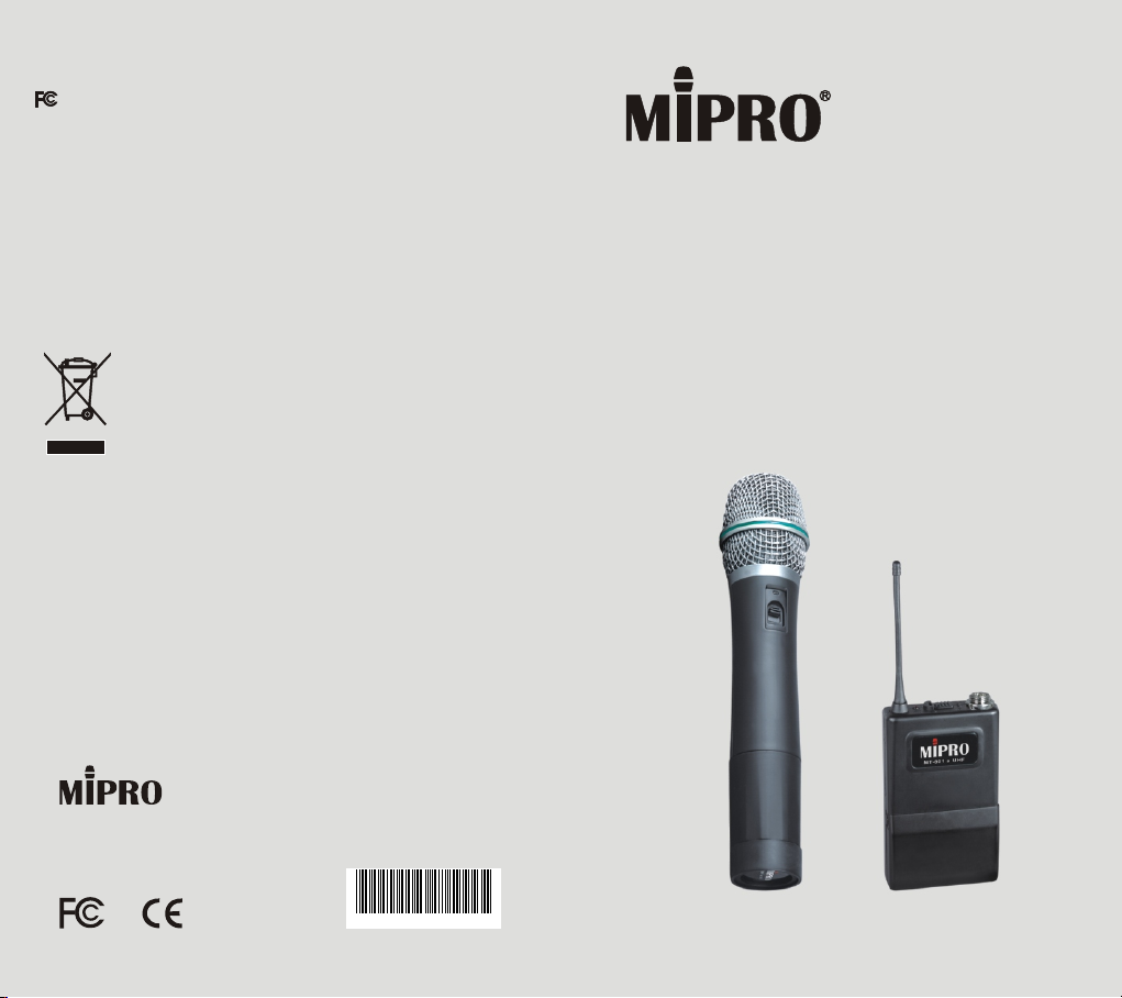
MH-801a UHF Handheld Transmitter
MT-801a Bodypack Transmitter
User Guide
MI PR O El ec tr on ic s Co ., L td .
Headquarters: 814 Pei-Kang Road, Chiayi, 60096, Taiwan.
Web: www.mipro.com.tw
E-mail: [email protected]
Design and specifications are subject to change without prior notice
AS101115
Page 2
UHF Handheld Transmitter
UHF Handheld Transmitter
KEY FEATURES
The MIPRO handheld wireless microphone is a
modular design. It also incorporates proprietary dual
squelch to eliminate noise interference.
Light, rugged housing.
Distinguished matte silver-gray color
grille.
Robust bullet-shaped microphone
ensures no impact-damage when
dropped.
Interchangeable microphone capsule
modules are available for replacement
and servicing. High dynamic range
allows high input level without
distortion.
PLL design ensures transmission
reliability.
A newly designed recessed power
switch is now located on the upper
housing for easier access.
A set of 10 different color bands is
available to enhance channel
identification.
Efficient transmission, low power
consumption and extremely low
handling noise.
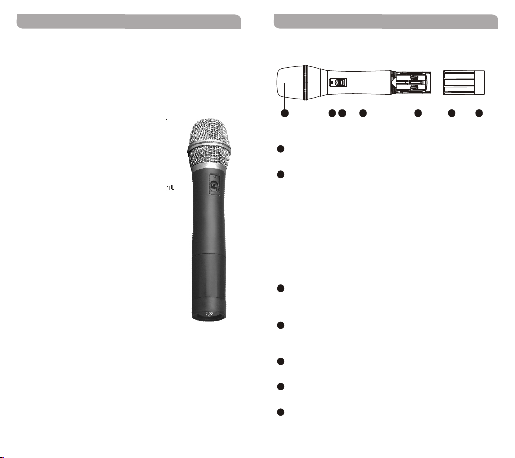
PART NAMES AND FUNCTIONS
4
1
1
Grille: Protects microphone capsule and
3
2
5
prevents breathing, wind and POP noises.
2
Battery Status Indicator: Indicates the power
on/off and battery status.
a. When the power switch is turned ON, the red
indicator flashes briefly and then go out, indicating
normal battery status.
b. If no flash occurs, it has either no battery, or the
battery is drained or installed incorrectly.
c. When the power switch is turned ON or during a
live performance, the red indicator stays lit,
indicating the battery level is low. A new battery
replacement is necessary.
3
Power On-off Switch: Slide the power switch
to the “ON” position for use or to the “OFF”
position when not in use.
4
Housing: Upper portion that is connected to the
capsule module. Internally it holds the
transmitter PCB and battery compartment.
5
Battery Compartment: Designed to
accommodate two 1.5V(AA) batteries.
6
Battery Cap: Covers the batteries in the battery
compartment.
7
Color Coded Protection Ring: Available in
different colors for channel differentiation.
6
(Figure 1)
7
1
2
Page 3
UHF Handheld Transmitter
UHF Handheld Transmitter
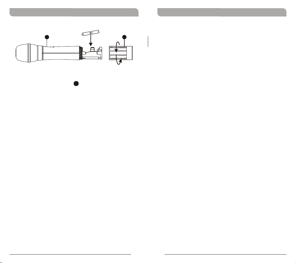
BATTERY INSERTION
2
6
(Figure 2)
1. Unscrew battery cap in a counter-clockwise
6
direction.
2. Insert two 1.5 Volt (AA) batteries into the
battery compartment according to the correct
polarity as shown in Figure 2. The moment the
battery touches the terminals of the
compartment, the indicator will flash briefly .
This means the polarity is correct. However, if
no flash occurs, this indicates wrong insertion
or battery is dead. Please re-insert the battery
according to its correct polarity or exchange it
for fresh batteries. Always change both
batteries at the same time.
OPERATING INSTRUCTIONS
When the microphone is switched on the indicator
will flash briefly indicating normal operation.
1. Powered-On:
RF signal LED indicator of the receiver
illuminates. .
2. After Powered-On:
The number of illuminated LEDs will increase
as the signal strength increases. If only the
red LED illuminates this indicates abnormal
receiving status.
3. During Usage:
The audio LED indicator of the receiver will
illuminates according to the sound strength
input to the microphone. When the red LED is
illuminated, it denotes the maximum sound
pressure level is being reached but does not
represent distortion.
NOTE: When microphone is not in use make sure the
microphone is switched off. If the microphone will not
be used for some time, please remove the batteries
from the battery compartment to avoid battery
leakage which could result in damage to the
microphone. If rechargeable batteries are used,
remove and recharge when necessary.
3
4
Page 4
UHF Handheld Transmitter
CAUTIONS
1. Performer should avoid holding the microphone over or near
the antenna section as this will deteriorate transmission
efficiency. Severe deterioration if performer directly covers up
the antenna section with both hands.
2. Many performers tend to hold the microphone by the top grille.
Unfortunately, this position seriously degrades both the sound
quality and directionality of a microphone. Even the most
expensive microphones will have its original sound quality
compromised by this method. Grabbing a microphone by the
grille will isolate the capsule's acoustic resonance circuit and or
change the capsule resonator's frequency. This results in an
inferior performance in both frequency response and the
separation of directionality. In addition, a palm's soundfocusing effect will tend to strengthen resonances in certain
frequencies and can cause unwanted echo.
3. A proper technique is required for using directional
microphones because the distance between the microphone
and your mouth has a significant impact on sensitivity and
performance. There is an inverse relationship between
microphone sensitivity and the distance from the mouth to the
microphone. Consequently, performers with a ''weaker'' sound
level cannot expect to hold the microphone too far away from
their mouth and compensate by turning up the amplifier
volume to increase the sound level as this can easily cause
echo or feedback. In contrast, performers with a ''louder''
sound level should not hold the microphone too close as this
can easily result in distortion by causing the amplifier system
to be overloaded.
4. Furthermore, a large-diaphragm directional microphone has a
very distinct proximity effect. When the microphone is close to
the mouth, the bass response is strengthened as the distance
gets closer. Therefore, if a performer's sound is insufficient in
bass, they can hold the microphone closer and use the
proximity effect to help compensate for the lower bass level.
Conversely, if a performer's voice is too heavy in the bass
register, increasing the distance between the microphone and
their mouth will decrease the proximity effect and reduce the
bass response, thus making their voice become clearer and
brighter.
5. It is recommended to keep the grille and sponge windscreen
clean to avoid any substance blocking the proximity effect of
the microphone.
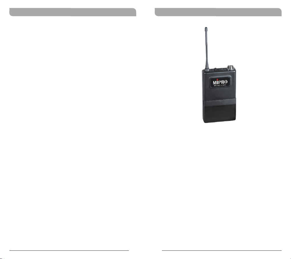
UHF Bodypack Transmitter
KEY FEATURES
! Housing unchanged.
! Industry standard 4-pin mini-XLR (TA4F)
connector is utilized for quick screw lock
connection.
! Accepts lavalier, headworn microphone and
instrument inputs with level adjustments.
! High dynamic range allows high input level
without distortion.
! PLL design ensures transmission reliability.
! Efficient transmission, low power consumption
and extremely low handling noise.
5
6
Page 5
UHF Bodypack Transmitter
UHF Bodypack Transmitter
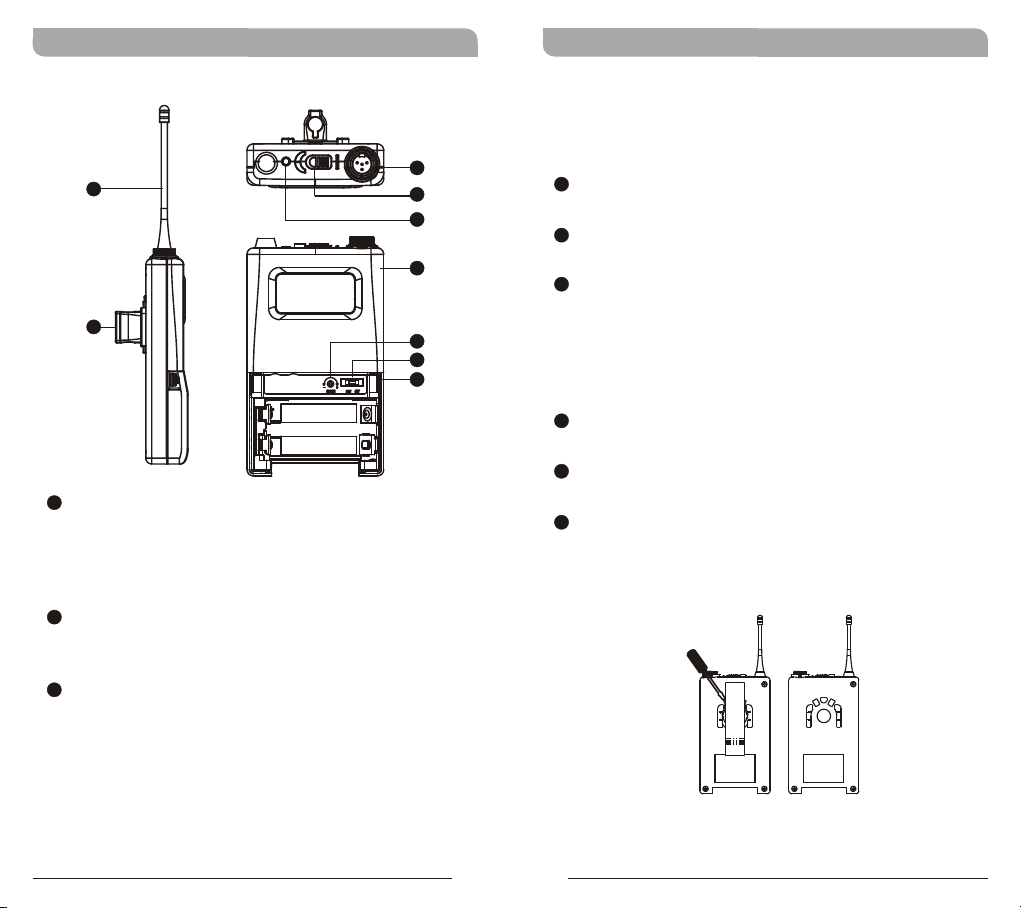
PART NAMES AND FUNCTIONS
8
9
1
4-pin Mini-XLR Connector: Connects to the
MIPRO 4-pin connector. For lavaliere, headset
microphone or instrument cable. Allows 5
different input configurations (See the five ways
of connection on an AF input connection)
2
Power Switch: Switch to ON position for
operation. Switch to OFF position when not in
use.
3
Battery Status Indicator: Indicates the power
on/off and battery status.
a. When the power switch is turned ON, the red
indicator flashes briefly and then go out,
indicating normal battery status.
b. If no flash occurs, it has either no battery, or
the battery is drained or installed incorrectly.
1
2
3
4
5
6
7
(Figure 1)
c. When the power switch is turned ON or
during a live performance, the red indicator
stays lit, indicating the battery level is low. A
new battery replacement is necessary.
4
Transmitter Housing: Contains the PCB and
battery.
5
Gain Control: Adjusts the input gain to an
appropriate level.
6
GT/MT Switch: Switch to the GT position for
electric guitar use ONLY. Gain Control is
irrelevant for “GT” mode. Switch to the “MT”
position for condenser microphone, wired
microphone or Line-in use. Gain Control works in
the “MT” mode for input sensitivity adjustments.
7
Battery Compartment and Cover:
Accommodates two 1.5V(AA) batteries.
8
Transmitting Antenna: 1/4 wavelength
transmitting antenna.
9
Detachable Belt Clip: Allows for 360 degrees of
rotating to suite transmitting angles. To detach
simply use a screwdriver on a 45 degree angle
to unfasten (see Figure 2).
(Figure 2)
7
8
Page 6

UHF Bodypack Transmitter
OPERATING INSTRUCTIONS
Select GT/MT Switch position: Determine
6
the use of the BodyPack transmitter. If a lavaliere
or headset microphone will be used the switch
should be set in the “MT” position. If a
guitar/bass or if used with a line level device (pre
amp out) the switch should be set in the “GT”
position.
Power On: When powering up the transmitter
switch the power switch to the ON position. The
Battery Status indicator will flash briefly
indicating normal operational status. When the
indicator remains illuminated or does not
illuminate at all the battery level is low or
exhausted and battery must be replaced for
continued operation.
Gain Control : Volume can be adjusted by
5
the gain control. Gain control has no effect when
the switch is in the “GT” position (Guitar).
4-pin Connector: Before making these
connections power down the transmitter to
prevent damage to the transmitter, receiver or
speaker system. Align and insert the 4-pin plug
into the connector accordingly and tighten it in
the clockwise direction illustrated in Figure 3.
Then power unit up again.
UHF Bodypack Transmitter
Capsule Connector
Headset
Lavalier
5
6
The cutout on the
connector must match
the indentation on the
socket when inserting.
(Figure 3)
9
10
Page 7
UHF Bodypack Transmitter
UHF Bodypack Transmitter
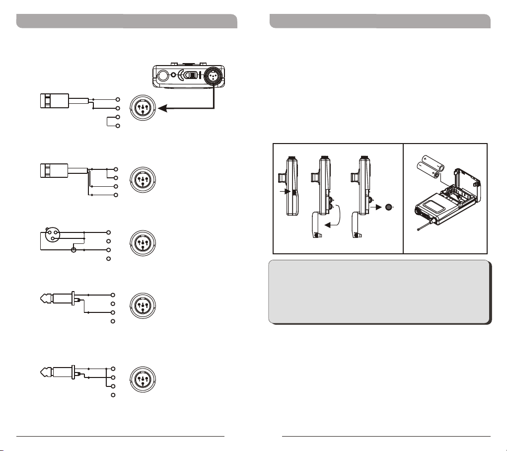
AF 4-PIN INPUT PIN CONFIGURATION
2-Wire Electret Condenser
Microphone Capsule
PINPIN
SHIELDSHIELD
11
AUDIOAUDIO
22
33
44
3-Wire Electret Condenser Microphone Capsule
PINPIN
SHIELDSHIELD
11
22
AUDIOAUDIO
33
BIASBIAS
44
Dynamic Microphone
PINPIN
22 11
33
Electric Guitar
SHIELDSHIELD
AUDIOAUDIO
SHIELDSHIELD
AUDIOAUDIO
11
22
33
44
PINPIN
11
22
33
44
BATTERY INSTALLATION
1. Pushing in with your thumb and index finger on
both battery cover snap locks to open battery
compartment as illustrated in Figure 4.
2. Insert two 1.5 Volt (AA) batteries input the
battery compartment being careful of the
proper polarity as illustrated in Figure 5. Close
up the battery compartment when done.
(Figure 4) (Figure 5)
NOTE: When microphone is not in use make sure the
microphone is switched off. If the microphone will not be
used for some time, please remove the batteries from the
battery compartment to avoid battery leakage which could
result in damage to the microphone. If rechargeable
batteries are used, remove and recharge when necessary.
Line-in (impedance 8KΩ a ttenuation 10dB)
PINPIN
SHIELDSHIELD
11
AUDIOAUDIO
22
33
44
11
12
 Loading...