

MIPRO ad-808 User Manual
4-channelActiveAntennaCombiner
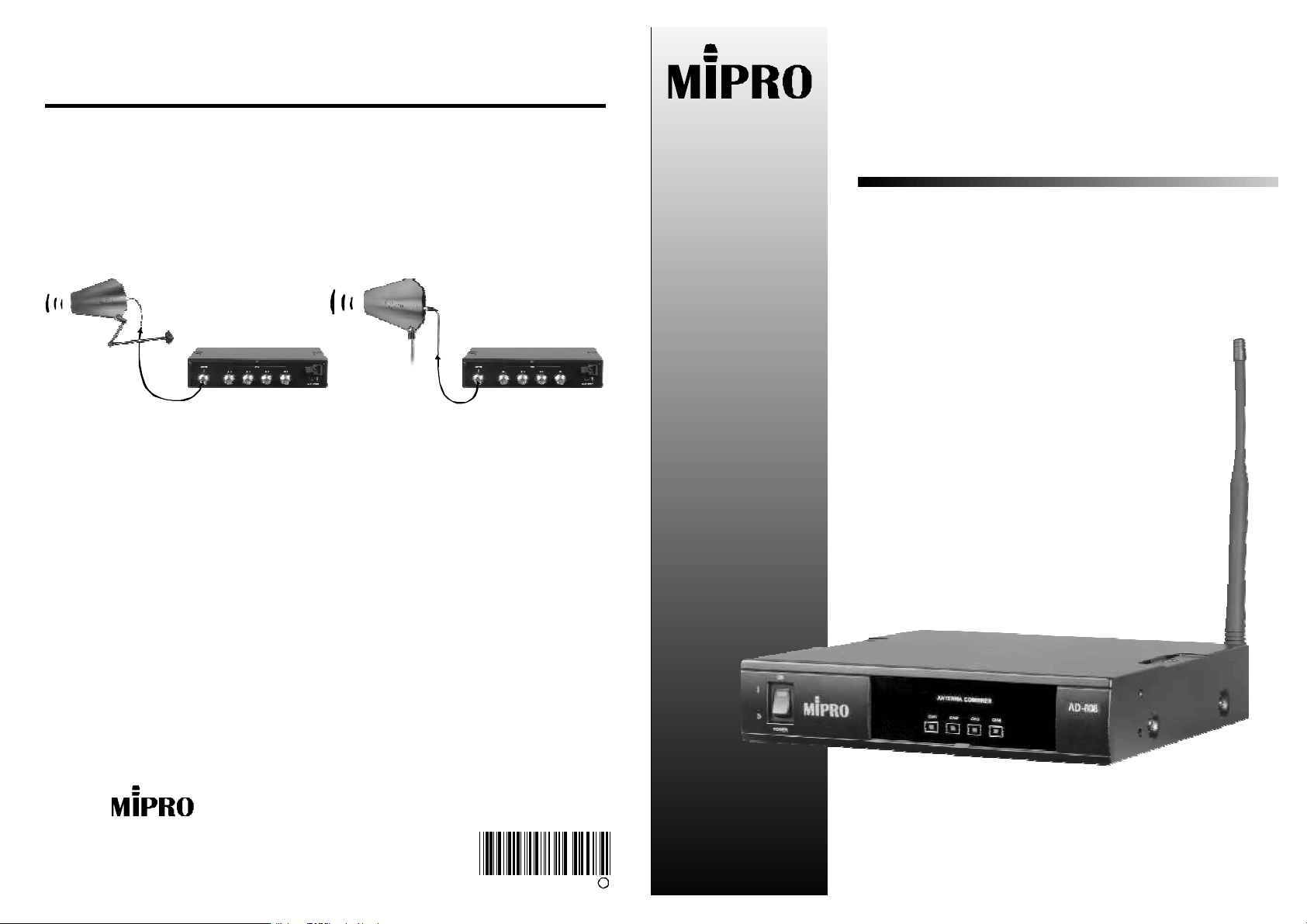
3.InstallationofExtensionAntennas
MIPROAT-70orAT-90TExtensionAntennascanbeinstalledwithMS-10
wallmountbracketsorgeneralmicrophonestandandconnectbycoaxial
cables.Itisrecommendedtousehigherqualitybutminimizedthelengthof
coaxialcablesandensureantennaispositionedhigherthanthecrowdand
awayfromobstacleobjectsforoptimalreception.
AT-90T
MS-10
Wide-bandExtensionAntennaStandWide-bandExtensionAntennaMountBrackets
4.PowerOn:
ThepowerindicatorlitswhenPoweron.Wheninputsignalislargerthan
66dBM,theLEDindicatorwilllit.
AD-808
OPERATINGMANUAL
4-channelActiveAntennaCombiner
3.Cautions:
Thefrequencyrangeisbetween600MHz~900MHz,anditworkswithany
MI-808Ttransmitterwithinthisspecifiedrange.Toobtainoptimaltransmission
efficiencyensurethetransmittingantennaisofthesamefrequencybandas
thetransmitteritself.AT-90Twidebanddirectionalantennasishighly
recommendedtoworkwithAD-808.
Use50impedancecoaxialcable(likeRG-58)toconnectthereceiverand
theantennacombinersystem.Coaxialcablewithin10metersisthe
recommendedlength.
Ω
Headoffice:814,Pei-KangRoad,Chiayi,600,Taiwan.
Taipeioffice:5,Lane118,Sung-tenRoad,100,Taipei,Taiwan.
http://www.mipro.com.tw
E-mail:mipro@mipro.com.tw 2CE226
MIPRO
ElectronicsCo.,Ltd.
B
4-channelActiveAntennaCombiner 4-channelActiveAntennaCombiner
ThankyouforchoosingMIPROAntennaCombinerSystem.Beforeoperating,
pleasereadtheinstructionscarefullyandcompletelyforoptimalperformance.
OUTPUT
CH4 CH3 CH2 CH1
INPUT
Thesystemincludesfollowingaccessories:
1.Operatingmanualx1
MainFunction:
AD-808isaprofessionalUHF4-channelactiveantennacombiner.The
operatingfrequencyrageisfrom600MHzto900MHz.Thissystemworks
withMIPROMI-808Ttransmitterorsimilarproducts.Uptofourwireless
transmitterscanbecombinedintoonetransmittingantennaformulti-channel
professionalapplications.
MainSpecifications:
1.Bandwidth:600MHz~900MHz.
2.Channels:Uptofourtransmitters.
3.Indicator:Equipswithasignalinputindicator.Inputsignalindicatorislitissignalis
largerthan66dBM.
4.Maximuminputpower:+20dBM(100mW).Idealintermodulationcharacteristic.
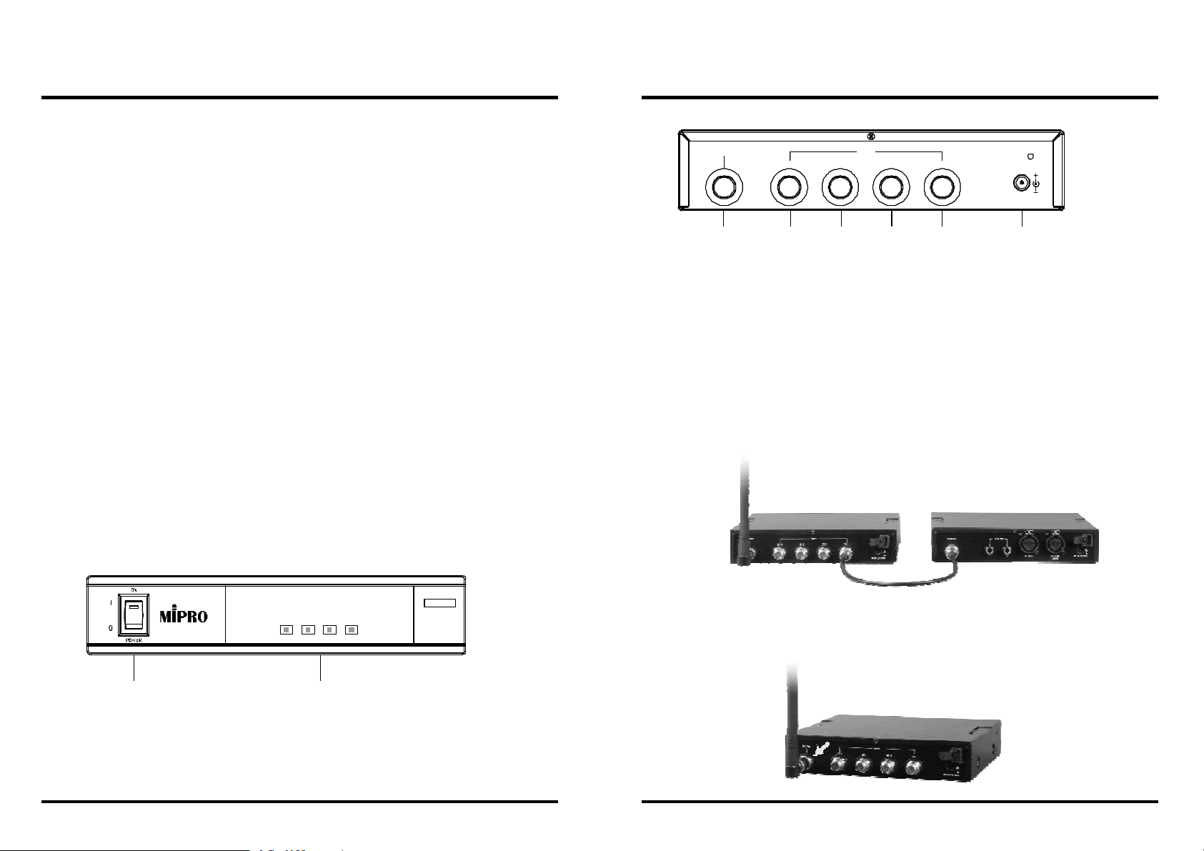
1.NamesandFeatures:
ANTENNACOMBINER
CH1 CH2 CH3 CH4
AD-808
DCIN(12~15V)
(3) (4) (4) (4) (5)(4)
(3)
AntennaoutputJack:
(4)
SignalinputJack:
(5)
DCPowerInputJack:
ToconnectthecombinedsignalandoutputtoAntenna
Toconnecttheoutputoffourtransmitters.
Toconnect12~15DCfromtheAC/DCadapter.
RearPanel
2.Installations:
1.Theinstallationofinputsignal
UsethecoaxialcableswithTNCconnectorstoconnecttheoutputsofMI-808
totheinputsofAD-808andthenfasten.
Ascertainlengthofthecoaxialcablesisasshortaspossibletoobtainthe
optimalreception.ThissystemconnectsuptofourMI-808Ttransmitters.
MI-808TAD-808
2.AntennaInstallation
Alignthecorrespondingcoaxialcablestoeachmatingoutputsofeachreceiver.
Foroptimaltransmission,ascertaintheantennasofthecombinerandMI-808T
transmittershavethesamefrequencybands.
(1) (2)
(1)
PowerOn/OffSwitch:
(2)
SignalInputIndicator:
indicatorlightlits.
FrontPanel
Whenpower-on,thelightilluminates.
Wheninputsignalislargerthan66dBM,the
 Loading...