

Page 1

VS-800
Vital Signs Monitor
Operator’s Manual
Page 2

Page 3

Intellectual Property Statement
SHENZHEN MINDRAY BIO-MEDICAL ELECTRONICS CO., LTD. (hereinafter
called Mindray) owns the intellectual property rights to this product and this manual.
This manual may refer to information protected by copyrights or patents and does not
convey any license under the patent rights of Mindray, nor the rights of others.
Mindray intends to maintain the contents of this manual as confidential information.
Disclosure of the information in this manual in any manner whatsoever without the
written permission of Mindray is strictly forbidden. Release, amendment,
reproduction, distribution, rental, adaption and translation of this manual in any
manner whatsoever without the written permission of Mindray is strictly forbidden.
and are the registered trademarks or trademarks owned by
Mindray in China and other countries. All other trademarks that appear in this manual
are used only for editorial purposes without the intention of improperly using them.
They are the property of their respective owners.
Contents of this manual are subject to changes without prior notice.
© 2005 - 2007 Shenzhen Mindray Bio-Medical Electronics Co., Ltd. All rights
reserved.
I
Page 4

Manufacturer’s Responsibility
All information contained in this manual is believed to be correct. Mindray shall not
be liable for errors contained herein nor for incidental or consequential damages in
connection with the furnishing, performance, or use of this manual.
Mindray is responsible for the effects on safety, reliability and performance of this
product, only if:
all installation operations, expansions, changes, modifications and repairs of this
product are conducted by Mindray authorized personnel; and
the electrical installation of the relevant room complies with the applicable
national and local requirements; and
the product is used in accordance with the instructions for use.
Warranty
This warranty is exclusive and is in lieu of all other warranties, expressed or implied,
including warranties of merchantability or fitness for any particular purpose.
Exemptions
Mindray's obligation or liability under this warranty does not include any
transportation or other charges or liability for direct, indirect or consequential
damages or delay resulting from the improper use or application of the product or the
use of parts or accessories not approved by Mindray or repairs by people other than
Mindray authorized personnel.
This warranty shall not extend to
Any Mindray product which has been subjected to misuse, negligence or
accident; or
Any Mindray product from which Mindray's original serial number tag or
product identification markings have been altered or removed; or
Any product of any other manufacturer.
II
Page 5

Return Policy
In the event that it becomes necessary to return a unit to Mindray, follow the
instructions below.
1. Return authorization.
Contact the Customer Service Department and obtain a Customer Service
Authorization number. This number must appear on the outside of the shipping
container. Returned shipments will not be accepted if the number is not clearly visible.
Please provide the model number, serial number, and a brief description of the reason
for return.
2. Freight policy
The customer is responsible for freight charges when this product is shipped to
Mindray for service (this includes customs charges).
3. Return address
Please send the part(s) or equipment to the address offered by the Customer Service
Department.
III
Page 6

Contact Information
Manufacturer: Shenzhen Mindray Bio-Medical Electronics Co., Ltd.
Address: Mindray Building, Keji 12th Road South, Hi-tech Industrial
Park, Nanshan, Shenzhen 518057, P. R. China
Tel: +86 755 26582479 +86 755 26582888
Fax: +86 755 26582934 +86 755 26582500
Website: www.mindray.com
EC-Representative: Shanghai International Holding Corp. GmbH (Europe)
Address: Eiffestraße 80, Hamburg 20537, Germany
Tel: 0049-40-2513175
Fax: 0049-40-255726
Manufacturer: Shenzhen Mindray Bio-Medical Electronics Co., Ltd.
IV
Page 7

Contents
1 Safety.................................................................................................................... 1-1
1.1 Safety Information ...................................................................................... 1-2
1.1.1 Dangers ......................................................................................... 1-3
1.1.2 Warnings ....................................................................................... 1-3
1.1.3 Cautions......................................................................................... 1-4
1.1.4 Notes ............................................................................................. 1-5
1.2 Equipment Symbols .................................................................................... 1-6
1.3 CE Marking................................................................................................. 1-7
1.4 Reference Literature.................................................................................... 1-8
2 The Basics ............................................................................................................ 2-1
2.1 Monitor Description .................................................................................... 2-2
2.1.1 Intended Use.................................................................................. 2-2
2.1.2 Contraindications .......................................................................... 2-2
2.1.3 Components................................................................................... 2-3
2.1.4 Functions ....................................................................................... 2-3
2.2 Appearance.................................................................................................. 2-4
2.2.1 Front Panel .................................................................................... 2-4
2.2.2 Rear Panel ..................................................................................... 2-8
2.2.3 Recorder ........................................................................................ 2-9
2.3 Display ...................................................................................................... 2-10
2.3.1 Cursor.......................................................................................... 2-10
2.4 Battery....................................................................................................... 2-11
2.4.1 Battery Maintenance ................................................................... 2-12
2.4.2 Battery Recycling........................................................................ 2-13
3 Installation and Maintenance............................................................................. 3-1
3.1 Installation................................................................................................... 3-2
3.1.1 Unpacking and Checking .............................................................. 3-2
3.1.2 Environmental Requirements........................................................ 3-3
3.1.3 Power Supply Requirements ......................................................... 3-3
3.1.4 Bracket Mounting.......................................................................... 3-3
3.1.5 Installation Method ....................................................................... 3-4
3.1.6 Powering on the Monitor............................................................... 3-8
3.1.7 Powering off the Monitor .............................................................. 3-8
3.2 Maintenance ................................................................................................ 3-9
3.2.1 Inspection ...................................................................................... 3-9
3.2.2 Cleaning ...................................................................................... 3-10
3.2.3 Disinfection ................................................................................. 3-11
1
Page 8

Contents
4 Menus and Screens.............................................................................................. 4-1
4.1 Patient Information Setup............................................................................ 4-2
4.2 System Setup............................................................................................... 4-3
4.2.1 Common Setup.............................................................................. 4-3
4.2.2 Default Setup................................................................................. 4-4
4.2.3 Nurse Call Setup............................................................................ 4-5
4.2.4 Network Setup............................................................................... 4-6
4.2.5 Data Output ................................................................................... 4-7
4.2.6 Time Setup .................................................................................... 4-7
4.2.7 Version .......................................................................................... 4-8
4.2.8 Maintenance .................................................................................. 4-8
4.3 Alarm Setup ................................................................................................ 4-9
4.4 Trend Data Screen..................................................................................... 4-10
4.5 PLETH Waveform Screen ........................................................................ 4-11
4.6 INTERVAL............................................................................................... 4-11
4.7 Standby State............................................................................................. 4-12
4.7.1 Entering the Standby State .......................................................... 4-12
4.7.2 Exiting the Standby State ............................................................ 4-13
5 Alarms.................................................................................................................. 5-1
5.1 Overview..................................................................................................... 5-2
5.1.1 Alarm Categories........................................................................... 5-2
5.1.2 Alarm Levels................................................................................. 5-3
5.2 Alarm Modes............................................................................................... 5-4
5.2.1 Visual Alarms................................................................................ 5-4
5.2.2 Audible Alarms ............................................................................. 5-4
5.2.3 Alarm Messages ............................................................................ 5-5
5.3 Alarm Status................................................................................................ 5-5
5.3.1 Alarms Disabled............................................................................ 5-5
5.3.2 Alarms Paused............................................................................... 5-6
5.3.3 System Silenced ............................................................................ 5-6
5.3.4 Status Switchover.......................................................................... 5-7
5.4 Clearing Alarms .......................................................................................... 5-8
5.5 When an Alarm Occurs ............................................................................... 5-9
6 Recording............................................................................................................. 6-1
6.1 Overview..................................................................................................... 6-2
6.2 Recorder Operations.................................................................................... 6-2
6.3 Installing Recorder Paper ............................................................................ 6-3
7 Management System Software........................................................................... 7-1
7.1 Installation and Uninstallation .................................................................... 7-3
7.1.1 Installing the PV Software ............................................................ 7-3
7.1.2 Uninstalling the PV Software........................................................ 7-5
7.1.3 Network Connection ..................................................................... 7-5
7.2 Main Window.............................................................................................. 7-6
2
Page 9

Contents
7.2.1 Menu Bar....................................................................................... 7-6
7.2.2 Patient Management...................................................................... 7-7
7.3 Software Functions...................................................................................... 7-8
7.3.1 Trend Review ................................................................................ 7-8
7.3.2 NIBP Review............................................................................... 7-10
8 SpO
Monitoring ................................................................................................. 8-1
2
8.1 Mindray SpO
Module ................................................................................ 8-3
2
8.1.1 Principles of Operation.................................................................. 8-3
8.1.2 Precautions .................................................................................... 8-3
8.1.3 Monitoring Procedure ................................................................... 8-4
8.1.4 Measurement Limitations.............................................................. 8-7
8.2 Masimo SpO
Module................................................................................. 8-9
2
8.2.1 Principles of Operation.................................................................. 8-9
8.2.2 Precautions .................................................................................. 8-12
8.2.3 Monitoring Procedure ................................................................. 8-13
8.2.4 Measurement Limitations............................................................ 8-13
8.2.5 Masimo Information.................................................................... 8-15
8.3 Nellcor SpO
Module................................................................................ 8-16
2
8.3.1 Principles of Operation................................................................ 8-16
8.3.2 Precautions .................................................................................. 8-19
8.3.3 Monitoring Procedure ................................................................. 8-20
8.3.4 Measurement Limitations............................................................ 8-20
8.3.5 Nellcor Information..................................................................... 8-22
9 NIBP Monitoring................................................................................................. 9-1
9.1 Overview..................................................................................................... 9-2
9.2 Monitoring Procedure ................................................................................. 9-3
9.2.1 Cuff Selection and Placement ....................................................... 9-3
9.2.2 Operation Guides........................................................................... 9-4
9.3 Measurement Limitations............................................................................ 9-6
9.4 Reset, Calibration and Test for Air Leakage............................................... 9-7
9.4.1 Reset.............................................................................................. 9-7
9.4.2 Calibration..................................................................................... 9-7
9.4.3 Test for Air Leakage ..................................................................... 9-9
9.5 Maintenance and Cleaning ........................................................................ 9-10
10 TEMP Monitoring............................................................................................. 10-1
10.1 Overview................................................................................................... 10-2
10.2 Monitoring Procedure ............................................................................... 10-4
10.2.1 TEMP position ............................................................................ 10-4
10.2.2 Oral Temperature Measurement.................................................. 10-4
10.2.3 Axillary Temperature Measurement............................................ 10-5
10.2.4 Rectal Temperature Measurement............................................... 10-5
10.2.5 Temperature Measurement in MONITOR Mode........................ 10-6
10.3 Precautions ................................................................................................ 10-7
3
Page 10

Contents
10.4 Maintenance and Cleaning........................................................................ 10-8
11 Accessories......................................................................................................... 11-1
11.1 SpO
Accessories ...................................................................................... 11-2
2
11.1.1 Mindray SpO
11.1.2 Masimo SpO
11.1.3 Nellcor SpO
Accessories.......................................................... 11-2
2
Accessories .......................................................... 11-3
2
Accessories ........................................................... 11-3
2
11.2 NIBP Accessories...................................................................................... 11-4
11.3 TEMP Accessories .................................................................................... 11-4
12 Appendices......................................................................................................... 12-1
Appendix A Product Specifications ................................................................. 12-2
A.1 Safety Classifications .................................................................. 12-2
A.2 Environmental Specifications...................................................... 12-3
A.3 Power Requirements ................................................................... 12-4
A.4 Hardware Specification ............................................................... 12-5
A.5 Signal Output............................................................................... 12-6
A.6 SpO
Specification ...................................................................... 12-7
2
A.7 NIBP Specification...................................................................... 12-9
A.8 TEMP Specification .................................................................. 12-10
Appendix B EMC........................................................................................... 12-11
Appendix C Alarm Messages and Prompt Information ................................. 12-16
C.1 Physiological Alarm Messages ................................................. 12-16
C.2 Technical Alarm Messages ....................................................... 12-16
C.3 Prompt Messages....................................................................... 12-25
Appendix D Symbols and Abbreviations....................................................... 12-27
D.1 Symbols..................................................................................... 12-27
D.2 Abbreviations ............................................................................ 12-29
4
Page 11

Preface
Manual Purpose
This manual provides the instructions necessary to operate the VS-800 Vital Signs
Monitor (hereinafter called as this monitor) in accordance with its function and
intended use. Observance of this manual is a prerequisite for proper performance
and correct operation, and ensures patient and operator safety.
This manual is written based on the maximum configuration. Part of this manual
may not apply to your monitor. If you have any question about the configuration of
your monitor, please contact our Customer Service.
This manual is an integral part of and should always be kept close to the monitor, so
that it can be obtained conveniently when necessary.
Intended Audience
This manual is geared for the clinical medical professionals. Clinical medical
professionals are expected to have working knowledge of medical procedures,
practices and terminology as required for monitoring of patients.
Version Information
This manual has a version number. This version number changes whenever the
manual is updated due to software or technical specification change. Content of this
manual is subject to change without prior notice. The version information of this
manual is as follows.
Version number Release date
2.4 October 2007
1
Page 12

Illustrations and Names
All illustrations in this manual are provided as examples only. They may not
necessarily accord with the graphs, settings or data displayed on your monitor.
All names appeared in this manual and illustrations are fictive. It is a mere
coincidence if the name is the same with yours.
Conventions
Italic text is used in this manual to quote the referenced chapters or sections.
The terms danger, warning, and caution are used throughout this manual to
point out hazards and to designate a degree or level or seriousness.
Preface
2
Page 13

1 Safety
1.1 Safety Information ...................................................................................... 1-2
1.1.1 Dangers ......................................................................................... 1-3
1.1.2 Warnings ....................................................................................... 1-3
1.1.3 Cautions......................................................................................... 1-4
1.1.4 Notes ............................................................................................. 1-5
1.2 Equipment Symbols .................................................................................... 1-6
1.3 CE Marking................................................................................................. 1-7
1.4 Reference Literature.................................................................................... 1-8
1-1
Page 14

Safety
1.1 Safety Information
The safety statements presented in this chapter refer to the basic safety information
that the operator of the monitor shall pay attention to and abide by. There are
additional safety statements in other chapters or sections, which may be the same as
or similar to the followings, or specific to the operations.
DANGER
z Indicates an imminent hazard situation that, if not avoided, will result in
death or serious injury.
WARNING
z Indicates a potential hazard situation or unsafe practice that, if not
avoided, could result in death or serious injury.
CAUTION
z Indicates a potential hazard or unsafe practice that, if not avoided,
could result in minor personal injury or product/property damage.
NOTE
z Provides application tips or other useful information to ensure that you
get the most from your product.
1-2
Page 15

Safety
1.1.1 Dangers
There are no dangers that refer to the product in general. Specific “Danger”
statements may be given in the respective sections of this operation manual.
1.1.2 Warnings
WARNING
z This monitor is not applicable for prolonged and continuous SpO2
monitoring, which may increase the risks of irritation and burns at the
site of the sensor.
z This monitor is not applicable for prolonged and continuous
temperature monitoring for more than 5 minutes.
z This monitor is intended for use by qualified clinical physicians or
well-trained nurses in the specified places.
z It is your responsibility to verify the device and accessories can
function safely and normally before use
z The disposable accessories should be disposed of in accordance with
the hospital regulations.
z A possible fire or explosion hazard exists when used in the presence of
flammable anesthetics or other flammable or explosive substances in
combination with air, oxygen-enriched environments, or nitrous oxide.
z You must customize the alarm setups according to the individual
patient situation, and make sure the alarm sound can be activated when
an alarm occurs.
z Opening the monitor housing presents a risk of hazard due to electrical
shock. All servicing and future upgrades to this equipment must be
carried out by personnel tranined and authorized by Mindray only.
z Do not touch the patient during defibrillation. A risk of serious injury or
death is present.
z When used in conjunction with electro-surgery equipment, you must
give top priority to the patient safety.
z Dispose of the package material, observing the applicable waste
1-3
Page 16

Safety
control regulations and keeping it out of children’s reach.
z The device must be connected to a properly installed power outlet with
protective earth contacts only. If the installation does not provide for a
protective earth conductor, disconnect the monitor from the power line
and operate it on battery power, if possible.
1.1.3 Cautions
CAUTION
z To ensure patient safety, use only parts and accessories specified in
this manual.
z Remove the battery from the monitor if it will not be used or not be
connected to the power line for a long period.
z Disposable devices are intended for single use only. They should not
be reused as performance could degrade or contamination could occur.
z At the end of its service life, the product described in this manual, as
well as its accessories, must be disposed of in compliance with the
guidelines regulating the disposal of such products. If you have any
questions concerning disposal of the products, please contact with us.
z Magnetic and electrical fields are capable of interfering with the proper
performance of the device. For this reason make sure that all external
devices operated in the vicinity of the monitor comply with the relevant
EMC requirements. Mobile phone, X-ray equipment or MRI devices are a
possible source of interference as they may emit higher levels of
electromagnetic radiation.
z Before connecting this monitor to the power line, check that the voltage
and frequency ratings of the power line are the same as those indicated
on the label or in this manual.
z Install or carry the monitor properly to avoid damages caused by drop,
impact, strong vibration or other mechanical force.
1-4
Page 17

Safety
1.1.4 Notes
NOTE
z Keep this manual close to the monitor so that it can be obtained
conveniently when necessary .
z This monitor complies with the requirements of CISPR11 (EN55011)
class A.
z The software was developed per IEC60601-1-4. The possiblility of
hazards arising from errors in software program is minimized.
z Put the monitor in a location where you can easily see the screen and
access the operating controls.
z The instructions of this manual are based on the maximum
configuration. Some of them may not apply to your monitor.
1-5
Page 18
Safety
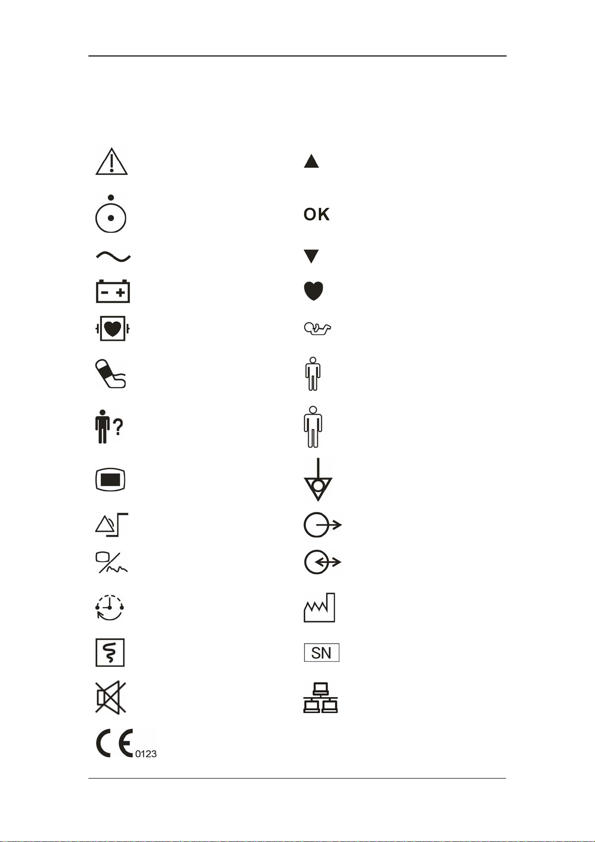
1.2 Equipment Symbols
Caution: Consult
accompanying documents
(this manual).
Up
Power ON/OFF
Alternating current (AC)
Battery indicator
Defibrillation-proof type CF
applied part
NIBP
PATIENT INFO.
MENU
Selection
Down
Pulse Rate (PR)
Neonate
Pediatric/Child
Adult
Equipotentiality
SET ALARMS
DISPLAY
INTERVAL
RECORD
SILENCE
CE marking
1-6
(Nurse call) Output
RS-232 connector
Date of manufacture
Serial number
Network connector
Page 19

1.3 CE Marking
The vital signs monitor bears CE mark CE-0123 indicating its conformity with the
provision of Council Directive 93/42/EEC concerning medical devices, and fulfills
the essential requirement of Annex I of this directive.
This monitor is in radio-interfernce protection class A in accordance with EN55011.
The product complies with the requirement of standard EN60601-1-2
“Electromagnetic Compatibility – Medical Electrical Equipment”.
Safety
1-7
Page 20

Safety
1.4 Reference Literature
1. COUNCIL DIRECTIVE 93/42/EEC of 14 June 1993 concerning medical
devices
2. IEC60601-1 or EN60601-1, Medical Electrical Equipment, Part 1: General
Requirements for Safety
3. IEC60601-1-1 or EN60601-1-1, Medical Electrical Equipment- Part 1-1:
General Requirements for Safety - Collateral Standard: Safety Requirements
for Medical Electrical Systems
4. IEC60601-1-4, Medical Electrical Equipment- Part 1-4: General Requirements
for Safety - Collateral Standard: Programmable Electrical Medical Systems.
5. IEC60601-2-49, Medical Electrical Equipment-Part 2-49: Particular
Requirements for the Safety of Multifunction Patient Monitoring Equipment.
1-8
Page 21

2 The Basics
2.1 Monitor Description .................................................................................... 2-2
2.1.1 Intended Use.................................................................................. 2-2
2.1.2 Contraindications .......................................................................... 2-2
2.1.3 Components................................................................................... 2-3
2.1.4 Functions ....................................................................................... 2-3
2.2 Appearance.................................................................................................. 2-4
2.2.1 Front Panel .................................................................................... 2-4
2.2.2 Rear Panel ..................................................................................... 2-8
2.2.3 Recorder ........................................................................................ 2-9
2.3 Display ...................................................................................................... 2-10
2.3.1 Cursor.......................................................................................... 2-10
2.4 Battery....................................................................................................... 2-11
2.4.1 Battery Maintenance ................................................................... 2-12
2.4.2 Battery Recycling.......................................................................... 2-13
2-1
Page 22

The Basics
2.1 Monitor Description
2.1.1 Intended Use
This Monitor is intended for monitoring the patient’s vital signs including
Non-invasive Blood Pressure (NIBP), Pulse Oxygen Saturation (SpO
(PR) and Temperature (TEMP) for single adult, pediatric and neonatal patient.
This Monitor is intended for use in the health-care institutions such as Outpatient
Clinics, Emergency Departments, Medical Floors, Clinics and Nursing Departments.
It, however, is not intended for critical patient monitoring, hospital transport or
home use.
), Pulse Rate
2
WARNING
z This Monitor is to be operated by clinical physicians or appropriate
medical staffs under the direction of physicians. The operator of the
monitor must be well tranined. Any operation by unauthorized or
non-tranined personnel is forbidden.
z The physiological parameters and the alarm information displayed by
the monitor are only for the reference of physicians, but cannot be used
directly to determine the clinical treatment.
CAUTION
z The environment and power supply of this monitor must meet the
requirements specified in Appendix A Product Specifications.
2.1.2 Contraindications
None
2-2
Page 23

2.1.3 Components
This monitor is composed of a main unit, NIBP cuff, SpO
Note that some of the mentioned parts are optional and may not be found on your
monitor.
2.1.4 Functions
This monitor has the following functions and features:
The Basics
sensor and TEMP probe.
2
SpO
NIBP measurement: systolic pressure (S), diastolic pressure (D), mean pressure
TEMP measurement: temperature (TEMP).
Alarm: support visual/audible alarm and prompt message.
Record: support the function of recording NIBP trend data and PLETH
Nurse call.
Storage of trend data: support the function of storing up to 1200 groups of
Powerful system menu.
Large LED digit display.
AdjustableLCD brightness and contrast.
Network communication: support the function of being connected to the CMS
measurement: pulse oxygen saturation (SpO2), pulse rate (PR), and SpO2
2
plethysmogram.
(M), and pulse rate (PR).
waveforms.
measured results.
or PC for data output or online upgrade.
Rechargeable lead-acid battery or lithium battery.
2-3
Page 24

2.2 Appearance
2.2.1 Front Panel
1
2
The Basics
4
3
5
6
7
8
9
10
11
14
15
16
17
18
19
20
21
22
23
24
25
26
27
12
13
28
Figure 2-1 Front Panel
2-4
Page 25

The Basics
1. Alarm indicator
The alarm indicator of this monitor is in compliance with the requirement of
EN60825-1 A11 Class 1 for LED. The LED indicator varies its flash color and
frequency to indicate different alarm levels. For details, refer to 5.2.1 Visual Alarms.
2. SYS
This LED digit displays the systolic pressure reading in the NIBP measurement.
3. DIA
This LED digit displays the diastolic pressure reading in the NIBP measurement. At
the right side of the NIBP reading, it is the NIBP unit: kPa or mmHg. NIBP UNIT
can be set in the system setup menu and the one flashes is the unit selected.
4. MAP
This LED digit displays the mean pressure reading in the NIBP measurement.
5. PR
This LED digit displays the PR value in the NIBP measurement or SpO
2
measurement, with the unit (bpm) on the right.
6. SpO
This LED digit displays the SpO
2
value, with the unit (%) on the right.
2
7. Temp
This LED digit displays the temperature reading. At the right side of the NIBP
reading, it is the TEMP unit: ℃ or ℉. TEMP UNIT can be set in system setup
menu and the one flashes is the unit selected
8. LCD
The LCD displays menus, trend data or PLETH trend graphs.
9. PATIENT INFO.
Press this key to switch between the PATIENT INFORMATION menu and the trend
table.
10. MENU
Press this key to switch between the SYSTEM SETUP menu and the trend table.
2-5
Page 26

The Basics
11. On/standby, working status indicator
Press this key to power on/off the monitor and to enter/exit the standby state. To
power off the monitor, press this key for more than 2 seconds.
Inside this key is a working status indicator:
ON: It indicates that the monitor is powered on;
OFF: It indicates that the monitor is powered off.
12. Battery indicator
It indicates the status of the battery. For details, refer to 2.4 Battery.
13. AC power indicator
ON: It indicates that the AC power is applied to the monitor;
OFF: It indicates that the monitor is not applied to the monitor.
14. Patient type indicator
It indicates the patient types: adult, pediatric or neonate.
15. Pulse strength indicator
It indicates the pulse strength of a patient.
16. RECORD
Press this key to start or stop the printing (recording).
17. NIBP status indicator
ON: It indicates that the monitor is performing the NIBP measurement;
OFF: It indicates that the monitor is not performing the NIBP measurement.
18. NIBP
Press this key to start an NIBP measurement, or press this key during measurement
to stop it.
19. SILENCE
Press this key to start a 2-minute alarm pause. Wihin the alarm pause time, the
system will return to the normal status when a new alarm occurs. Press this key for
more than 2 seconds to disable all sounds or tones of the system, thus entering the
silience mode.
2-6
Page 27

The Basics
20. Silence indicator
OFF: normal status; in this status, when an alarm occurs, the system can give
an audible alarm according to the alarm level;
ON: system silenced status; in this status, the system cannot give any sound,
including audible alarm, key tone, and pulse tone.
FLASH: alarm paused status; in this status, the system cannot give the audible
and visual alarm.
21. Up
Press this key to move the cursor upward.
22. OK
Press this key to select the highlighted option.
23. Down
Press this key to move the cursor down.
24. INTERVAL
Press this key to switch between the INTERVAL menu and the trend table.
25. DISPLAY
Press this key to switch between the PLETH (plethysmogram) waveform and trend
table.
26. NIBP cuff connector
This connector is used to connect the NIBP cuff to the monitor.
27. SpO
This connector is used to connect the SpO
sensor connector
2
sensor to the monitor.
2
28. SET ALARMS
Press this key to switch between the SET ALARMS menu and the trend table.
2-7
Page 28
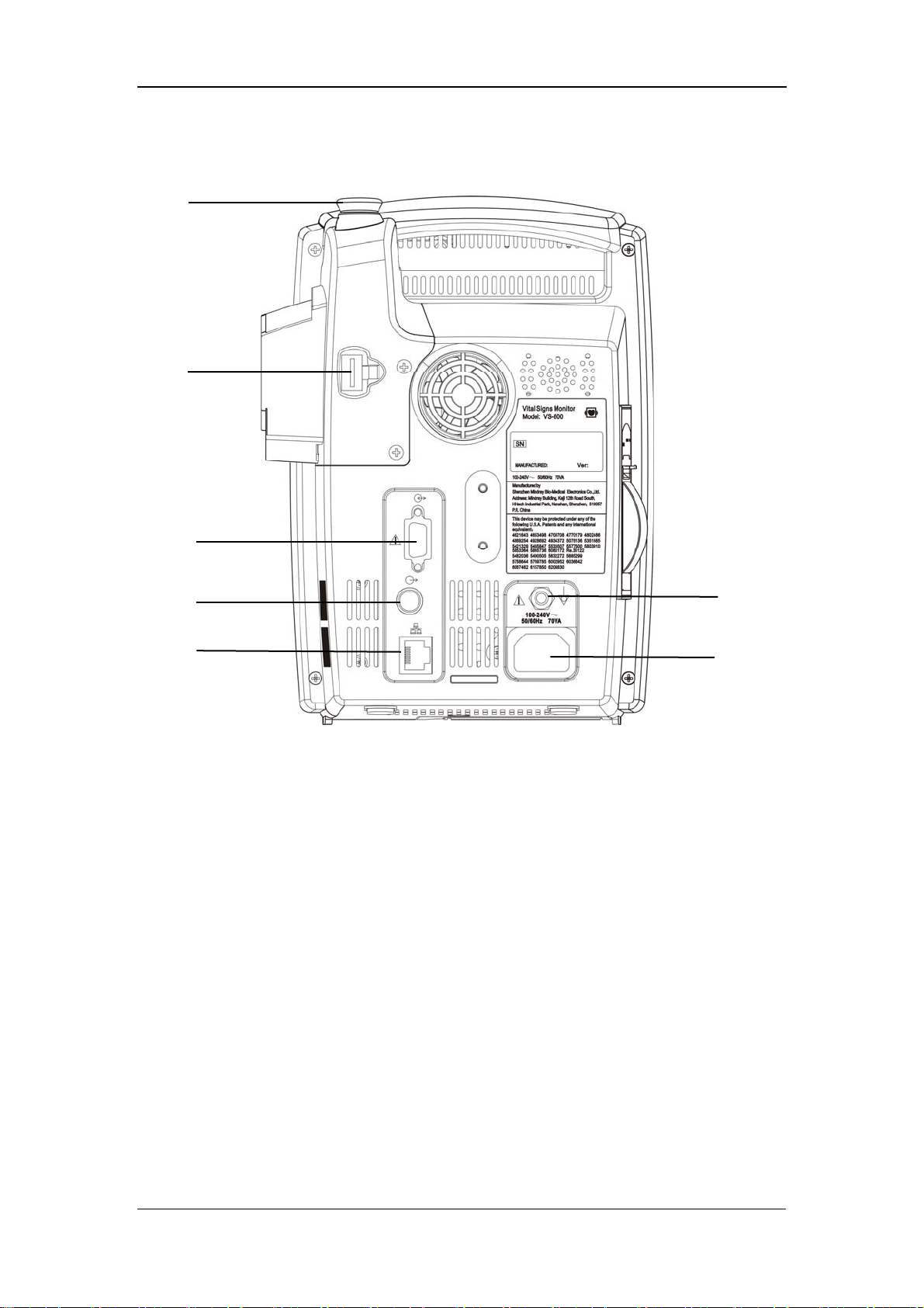
2.2.2 Rear Panel
1
2
The Basics
3
4
5
Figure 2-2 Rear Panel
1. TEMP probe sheath
2. TEMP probe connector
3. RS-232 connector:
4. Nurse call connector: used to connect the monitor to the nurse call system in
hospital.
5. Network connector: used to connect the monitor to the CMS(and CMS+) or
PC.
6. Equipotential grounding connector: connects the equipotential grounding
connectors of other devices.
6
7
7. AC power input connector: used to connect the monitor to the AC power
through a 3-core power cable.
2-8
Page 29
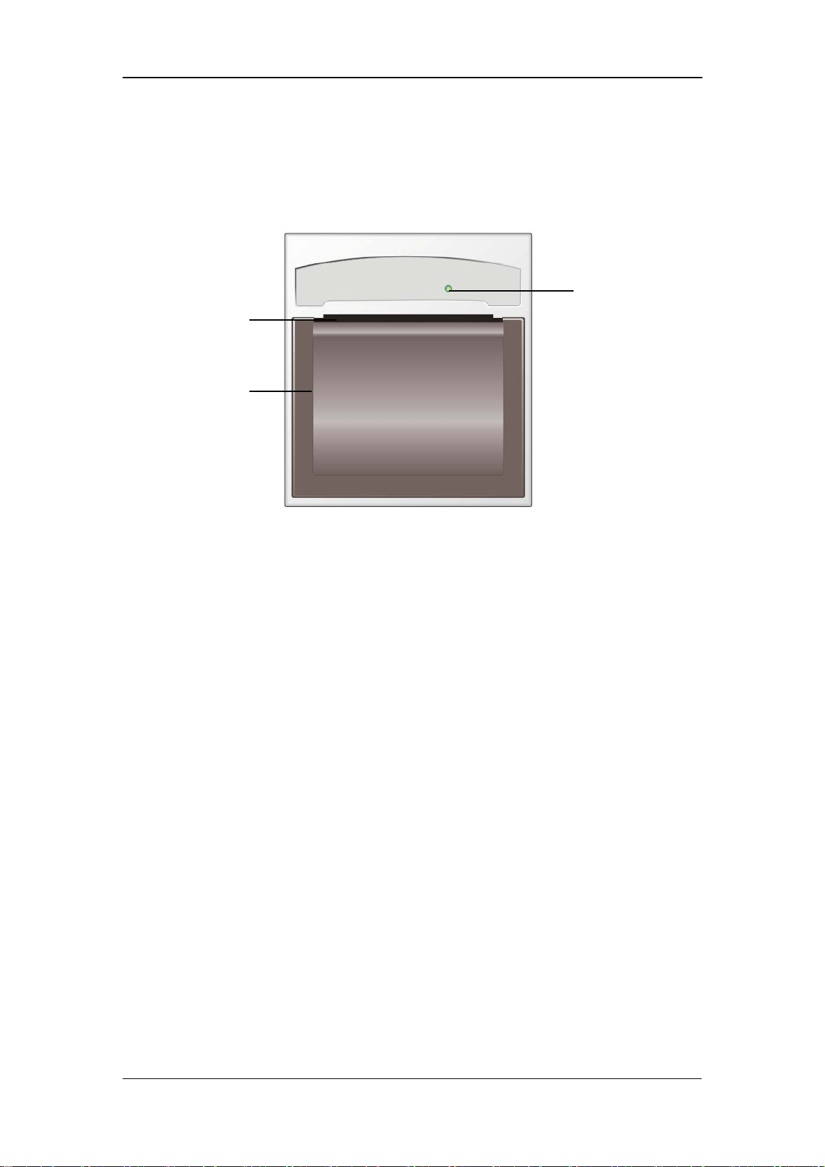
2.2.3 Recorder
The recorder is on the left side of the monitor. See the following figure.
Paper outlet
Recorder door
The Basics
Power indicator
Figure 2-3 Recorder
For details about the recorder, refer to 6 Recording.
2-9
Page 30

2.3 Display
1
2
The Basics
3
Figure 2-4 Display
This monitor adopts the LCD display. It is able to display the following three parts:
1. Title bar
In the title bar are menus or screen titles.
2. Main display area
In the main display area are menus, trend data or plethysmogram (PLETH for short)
waveforms.
3. Notification area
On the left of the notification area is the technical alarm message or prompt message.
If there are multiple messages, they will be displayed here in turns.
On the right of the notification area are the patient ID and current system time.
When a pysiological alarm occurs, the pysiological alarm message, patient ID and
system time will be displayed here in turns; when an alarm pause is started, the
system will prompt “ALARM PAUSED XXX s”.
2.3.1 Cursor
In menus or trend data screens, when the cursor moves to an option or a data, the
background of the option or the data will become black and the fonts will become
white. You can press
select the highlighted option or data for the next the operation.
or to move the cursor, and press to
NOTE
z and are used to move the cursor, and is used for
“Selection”.
2-10
Page 31

2.4 Battery
Rechargeable batteries can be used to supply power to the monitor for transport or
whenever the power supply is interrupted. The battery is charged automatically
when the monitor is connected to AC mains till it is full. If the power supply is lost
during monitoring, the monitor can run on the power supplied by the internal
battery.
The battery indicator indicates the status of the battery.
ON: The battery is being charged or the battery is fully charged.
OFF: The battery is removed from the monitor or the battery in the monitor is
depleted. If the monitor is equipped with battery but is not connected to AC
mains and not turned on, the indicator will also be off.
The Basics
Flashes: The indicator light flashes when the monitor is powered by the internal
battery.
The capacity of the internal battery is limited. When the battery capacity is too low,
a high level alarm is triggered and the “Battery too low” message is given in the
technical alarms area. At this moment, the AC mains shall be applied to the monitor;
otherwise the monitor will power off automatically before the battery is depleted.
For details about installation of the battery, refer to 3.1.5 Installation
Method:Installing the battery.
NOTE
z Remove the battery before transport, or if the monitor is not likely to be
used for an extended period of time.
WARNING
z Keep the battery out of the reach of children.
z Use only the battery specified by the manufacturer.
2-11
Page 32

2.4.1 Battery Maintenance
Conditioning a Battery
A battery should be conditioned before it is used for the first time. A battery
conditioning cycle is one uninterrupted charge of the battery, followed by an
uninterrupted discharge of the battery. Batteries should be conditioned regularly to
maintain their useful life. Condition a battery once when it is used or stored for two
months, or when its run time becomes noticeably shorter.
To condition a battery, follow this procedure:
1. Disconnect the monitor from the patient and stop all monitoring or measuring.
2. Insert the battery in need of conditioning in the battery slot of the monitor.
3. Apply AC power to the monitor and allow the battery to charge uninterrupted
for 10 hours.
The Basics
Remove AC power and allow the monitor to run from the battery until it shuts off.
4.
5. Apply AC power again to the monitor and allow the battery to charge
uninterrupted for 10 hours.
6. This battery is now conditioned and the monitor can be returned to service.
Checking a Battery
The performance of a rechargeable battery may deteriorate over time. To check the
performance of a battery, follow this procedure:
1. Disconnect the monitor from the patient and stop all monitoring or measuring.
2. Apply AC power to the monitor and allow the battery to charge uninterrupted
for 10 hours.
3. Remove AC power and allow the monitor to run from the battery until it shuts
off.
4. The operating time of battery reflects its performance directly.
If your monitor has two battery slots, you can check two batteries at the same time.
Please replace the battery or contact with the maintenance personnel if its operating
time is significantly lower than the specified time.
2-12
Page 33

The Basics
NOTE
z Life expectancy of a battery depends on how frequent and how long it
is used. For a properly maintained and stored lead-acid or lithium ion
battery, its life expectancy is about 2 or 3 years respectively. For more
aggressive use models, life expectancy can be less. We recommend
replacing lead acid batteries every 2 years and lithium ion batteries
every 3 years.
z The battery might be damaged or malfunctioned if its operating time is
too short after being fully charged. The operating time depends on the
configuration and operation. For example, measuring NIBP more
frequently will also shorten the operating time.
2.4.2 Battery Recycling
When a battery has visual signs of damage, or no longer holds a charge, it should be
replaced. Remove the old battery from the monitor and recycle it properly. To
dispose of the batteries, follow local laws for proper disposal.
WARNING
z Do not disassemble batteries, or dispose of them in fire, or cause them
to short circuit. They may ignite, explode, leak or heat up, causing
personal injury.
2-13
Page 34

FOR YOUR NOTES
The Basics
2-14
Page 35

3 Installation and Maintenance
3.1 Installation................................................................................................... 3-2
3.1.1 Unpacking and Checking .............................................................. 3-2
3.1.2 Environmental Requirements........................................................ 3-3
3.1.3 Power Supply Requirements ......................................................... 3-3
3.1.4 Bracket Mounting.......................................................................... 3-3
3.1.5 Installation Method ....................................................................... 3-4
3.1.6 Powering on the Monitor............................................................... 3-8
3.1.7 Powering off the Monitor.............................................................. 3-8
3.2 Maintenance ................................................................................................ 3-9
3.2.1 Inspection ...................................................................................... 3-9
3.2.2 Cleaning ...................................................................................... 3-10
3.2.3 Disinfection ................................................................................. 3-11
3-1
Page 36

Installation and Maintenance
3.1 Installation
WARNING
z The installation of the monitor must be carried out by personnel
authorized by Mindray. The software copyright of the monitor is solely
owned by our company. Any action to change, copy or exchange the
software by any organization or person is regarded as copyright
infringement and is not allowed.
3.1.1 Unpacking and Checking
Before unpacking, examine the packing case carefully for signs of damage. If any
damage is detected, contact the carrier or our company.
If the packing case is intact, open the package and remove the instrument and
accessories carefully. Check all materials against the packing list and check for any
mechanical damage. Contact our Customer Service Department for any problem.
NOTE
z Please save the packing case and packaging material for future
transport and storage.
WARNING
z Dispose of the packaging material, observing the applicable waste
control regulations and keeping it out of children’s reach.
z The equipment might be contaminated in storage, transport or when
used. Verify the package and the single use accessories are intact. In
case of any damage, do not apply it to patients.
3-2
Page 37

Installation and Maintenance
3.1.2 Environmental Requirements
The operating environment of the monitor must meet the requirements specified in
the section A.2Environmental Specifications of Appendix A Product
Specifications.
The environment where this monitor is to be used should be free from noise,
vibration, dust, and corrosive or explosive and inflammable substances. For a
cabinet mounted installation, allow sufficient room at the front and the rear of the
cabinet for operation, maintenance and servicing. Besides, allow at least 2 inches
clearance around the instrument for proper air circulation.
Condensation can form when the monitor is moved from one location to another,
and being exposed to differences in humidity or temperature. Make sure that during
operation the instrument is free from condensation.
3.1.3 Power Supply Requirements
The power applied to the monitor must meet the requirements specified in the
section A.3Power Requirements of Appendix A Product Specifications.
WARNING
z Make sure that the operating environment and the power applied to the
monitor comply with the specified requirements. Otherwise its
performance might not meet the specifications claimed in Appendix A
Product Specifications, and unexpected results, such as damages to
the monitor, may be incurred.
z The monitor shall be powered according to the requirement for the
system power voltage. Otherwise, serious damage might be caused to
the system.
3.1.4 Bracket Mounting
For details, please refer to the corresponding instructions for use of bracket
mounting
3-3
Page 38

Installation and Maintenance
3.1.5 Installation Method
WARNING
z Accessory equipments connected to this monitor must be certified
according to the respective IEC standards (e.g. IEC 60950 for
information technology equipment and IEC 60601-1 for medical
electrical equipment). Furthermore all configurations shall comply with
the valid version of the system standard IEC 60601-1-1. Any person
who connects additional equipment to the signal input or signal output
is responsible to ensure the system complies with the requirements of
the valid version of the system standard IEC 60601-1-1. If in doubt,
contact our company or customer service.
z If the monitor is connected to another electrical instrument and the
instrument specifications cannot tell whether the instrument
combination is hazardous (e.g. due to summation of leakage currents),
you should consult Mindray or experts in the field to ensure the
required safety of all instruments concerned.
NOTE
z The following operations are not all required. User-customized
installation by authorized personnel is provided.
Connecting to AC mains
1. Use the original 3-core power cable.
2. Connect the power cable to the AC mains input connector on the rear panel of
the monitor.
3. Connect the other end of the power cable to a compatible 3-prong hospital
grade AC power outlet.
The 3-prong power outlet must be grounded. In case of any doubt, contact related
personnel of the hospital.
3-4
Page 39

Installation and Maintenance
WARNING
z Do not use three-wire to two-wire adapter with this instrument.
z To avoid unexpected power interruption, do no use power outlet with a
wall-mounted switch control.
Installing the battery
The battery compartment is located at the bottom of the patient monitor. Follow the
steps given below to install the battery.
1. Push the compartment door in the marked direction to open the door.
2. Flip the battery stopper to the left, as Figure 3-1 shows.
3. Follow the marked polarity to insert the battery into the compartment, as Figure
3-2shows.
4. Push the battery all the to the bottom and flip the stopper back to the original
position, as Figure 3-3 shows.
5. Close the battery door.
Figure 3-1
3-5
Page 40

Installation and Maintenance
Figure 3-2
Figure 3-3
NOTICE
z Be sure to charge the battery after a long-term storage or when you find
the battery energy is low. A low-energy battery may not provide enough
power to start the patient monitor.
z To charge the battery, connect the AC power to the monitor. The battery
will be charged regardless the monitor is on or off.
Equipotential Grounding
When other equipments are used together with the monitor, a grounding cable
should be used to connect the equipotential grounding connectors of the monitor and
of other equipments. This helps to reduce the potential differences between different
pieces of equipment, and ensure the safety of the operator and patient.
3-6
Page 41

Installation and Maintenance
WARNING
z If the grounding system is in doubt, the monitor must be supplied from
its internal battery.
Connecting the accessories
Connect the necessary sensors or probes to the monitor. For details, see the chapters
for specific parameter monitoring in the following pages, or corresponding
instructions for sensors and probes.
Connecting the network cable
The network connector of the monitor is a standard RJ45 connector. It connects the
monitor with the central monitoring system, or with a PC for online upgrade or data
output.
1. Connect one end of the network cable to the network connector of the monitor.
2. Connect the other end of the network cable to the hub of the central monitoring
system, or to the network connector of a PC.
WARNING
z The system upgrading through the network connector is to be executed
by Mindray authorized personnel only.
Nurse call connector
The nurse call connector is used for the nurse call function. If connected to the nurse
call system of the hospital through a special nurse call cable, the monitor can
generate nurse call signals when alarms occur. The output end of the nurse call cable
consists of two free cords that is neutral. The installation should be done according
to the nurse call system by the maintenance engineer from the manufacturer or the
engineer of the hospital.
3-7
Page 42

Installation and Maintenance
WARNING
z This Monitor is to be operated by clinical physicians or appropriate
medical staffs under the direction of physicians. The operator of the
monitor must be well trained. Any operation by unauthorized or
non-trained personnel is forbidden.
3.1.6 Powering on the Monitor
After installing the monitor, please power on it in the following procedure:
1. Before using the monitor, please carry out corresponding safety inspection in
accordance with 3.2.1 Inspection.
2. Press the Power Switch on the control panel. A beep will be heard.
3. The system starts self-test and the start-up screen will be displayed.
4. Several seconds later, the system finishes the self-test and displays the main
screen.
5. Then you can operate the monitor through the control panel.
3.1.7 Powering off the Monitor
To power off the monitor, please follow the procedures below:
1. Confirm the patient monitoring is to be finished.
2. Disconnect the cables and sensors between the monitor and the patient.
3. Confirm whether to store or clear the patient monitoring data.
4. Press the Power switch and hold it for more than 2 seconds to power off the
monitor.
3-8
Page 43

Installation and Maintenance
3.2 Maintenance
WARNING
z Failure on the part of the responsible hospital or institution employing
the monitoring equipment to implement a satisfactory maintenance
schedule may cause undue equipment failure and possible health
hazard.
z The safety inspection before equipment disassembly or the servicing of
the equipment must be performed by professional servicing personnel.
Otherwise, equipment failure and possible health hazard may be
caused.
3.2.1 Inspection
Make sure the qualified service personnel have implemented a complete inspection
before putting the monitor into operation, after monitor servicing or system
upgrading, or after the monitor has been used for 6-12 consecutive months. This is
to ensure the normal operation of the system.
Check whether
The environment and the power supply meets the specified requirements.
The monitor cover is free from stains.
The monitor cover, keys, connectors and accessories are physically damaged.
The power cords are worn and the insulation is in good performance.
The grounding cables are properly connected.
Only specified accessories like electrodes, sensors and probes are applied.
The monitor clock is correct.
The audible and visual alarms are normal.
The recorder functions normally and the recorder paper meets the requirement.
The monitoring functions of the system are in good performance.
In case of any damage or exception, do not use the monitor. Contact the biomedical
engineers of the hospital or our Customer Service immediately.
3-9
Page 44

Installation and Maintenance
3.2.2 Cleaning
WARNING
z Be sure to shut down the system and disconnect all power cords from
the outlet before cleaning the equipment.
Your equipment should be cleaned regularly. If there is heavy pollution or lots of
dust and sand in your place, the equipment should be cleaned more frequently.
Before cleaning the equipment, consult your hospital’s regulations for cleaning,
disinfecting and sterilizing equipment.
The exterior surfaces of the equipment may be cleaned with a clean and soft cloth,
sponge or cotton ball, dampened with a non-erosive cleaning solution. Drying off
excess cleaning solution before cleaning the equipment is recommended. Following
are examples of cleaning solutions:
Diluted soap water
Diluted ammonia water
Diluted sodium hyoichlo (bleaching agent)
Diluted formaldehyde (35 to 37%)
Hydrogen peroxide (3%)
Ethanol (70%), or Isopropanol (70%)
NOTE
z The ssodium hypochlorite of the concentration ranging from 500ppm
(1:100 diluted bleaching agent for home use) to 5000ppm (1:10 diluted
bleaching agent for home use) is effective. The required concentration
depends on the quantity of the organic substances (such as blood,
mucus) on the equipment surface.
To avoid damage to the equipment, please follow these rules:
ALWAYS dilute the solutions according to the manufacturer’s suggestions.
3-10
Page 45

Installation and Maintenance
ALWAYS wipe off all the excess cleaning solution with a dry cloth after
cleaning.
NEVER submerge the equipment into water or any cleaning solution, or pour
or spray water or any cleaning solution on the equipment.
NEVER permit fluids run into the casing, switches, connectors, or any
ventilation openings in the equipment.
NEVER use abrasive or erosive cleaners of any kind as well as cleaners
containing acetone.
CAUTION
z Failure to follow these rules may erode or fray the casing, or blur
lettering on the labels, or cause equipment failures.
For cleaning information of accessories, please refer to the chapters for specific
patient parameters and the instructions for use of the accessories.
3.2.3 Disinfection
WARNING
z Disinfection or sterilization may cause damage to the equipment;
therefore, when preparing to disinfect or sterilize the equipment,
consult your hospital’s infection controllers or professionals.
z The cleaning solutions above can only be used for general cleaning. If
you use them to control infections, we shall assume no responsibility
for the effectiveness.
Disinfection may cause damage to the equipment. We recommend the sterilization
and disinfection are contained in the hospital’s servicing schedule only when
necessary. The equipment should be cleaned prior to sterilization and disinfection.
Recommended sterilization material: Alcohol based (Ethanol 70%, Isopropanol
70%), and aldehyde based.
3-11
Page 46

Installation and Maintenance
WARNING
z ALWAYS dilute the solutions according to the manufacturer’s
suggestions and adopt lower concentration if possible.
z NEVER submerge the equipment into water or any solution, or pour
water or any solution on the equipment.
z ALWAYS wipe off all the excess liquids on the equipment surface and
accessory surface with a dry cloth.
z NEVER use EtO and formaldehyde to disinfect the equipment.
z Never permit high-pressure and high-temperature disinfection of the
equipment and accessories.
3-12
Page 47

4 Menus and Screens
4.1 Patient Information Setup............................................................................ 4-2
4.2 System Setup............................................................................................... 4-3
4.2.1 Common Setup.............................................................................. 4-3
4.2.2 Default Setup................................................................................. 4-4
4.2.3 Nurse Call Setup............................................................................ 4-5
4.2.4 Network Setup............................................................................... 4-6
4.2.5 Data Output ................................................................................... 4-7
4.2.6 Time Setup .................................................................................... 4-7
4.2.7 Version .......................................................................................... 4-8
4.2.8 Maintenance .................................................................................. 4-8
4.3 Alarm Setup ................................................................................................ 4-9
4.4 Trend Data Screen..................................................................................... 4-10
4.5 PLETH Waveform Screen ........................................................................ 4-11
4.6 INTERVAL............................................................................................... 4-11
4.7 Standby State............................................................................................. 4-12
4.7.1 Entering the Standby State .......................................................... 4-12
4.7.2 Exiting the Standby State .............................................................. 4-13
4-1
Page 48

Menus and Screens
4.1 Patient Information Setup
By pressing
following figure), and by pressing this key again, you can switch to the trend data
screen.
In the PATIENT INFORMATION menu, you can set
PATIENT ID: 1 - 100
PATIENT TYPE: ADU (adult), NEO (neonate), PED (pediatric)
TEMP TYPE: PREDICT, MONITOR
TEMP POSITION: ORAL, AXILLARY, RECTAL. TEMP POSTION displays
on the LED DISPLAY by an icon.
, you can open the PATIENT INFORMATION menu (see the
Figure 4-1
To set the patient information
, and are used for moving the cursor and selecting the
highlighted option. They are most frequently used keys in menu operations. Take the
patient type setup as an example:
1. In the PATIENT INFORMATION menu, press
cursor to the option on the right of PATIENT TYPE.
2. Press
3. Press
4. Press
to select this option.
or to select the patient type as required.
to confirm the selected patient type.
or to move the
4-2
Page 49
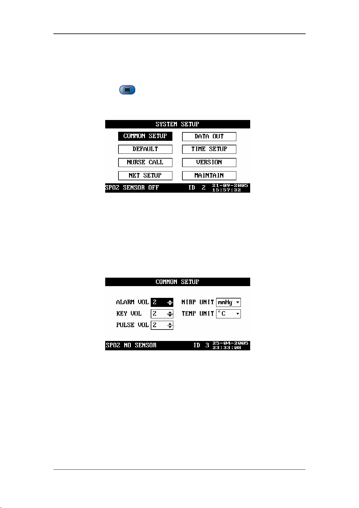
4.2 System Setup
By pressing on the front panel of the monitor, you can open the SYSTEM
SETUP menu (See the following figure).
Menus and Screens
Figure 4-2
4.2.1 Common Setup
In the SYSTEM SETUP menu, select COMMON SETUP. The COMMON SETUP
menu appears, as shown in the following figure.
ALARM VOL 1 - 10
KEY VOL 0 - 10
Figure 4-3
PULSE VOL 0 - 10
NIBP UNIT mmHg, kPa
TEMP UNIT ºC, ºF
The minimum alarm volume is 1 and the maximum alarm volume is 10. When the
key volume or pulse volume is set to 0, it indicates that the key tone or pulse tone is
disabled.
4-3
Page 50

4.2.2 Default Setup
In the SYSTEM SETUP menu, select DEFAULT. The DEFAULT menu appears, as
shown in the following figure.
During monitoring process, you may modify some configurations as required, which,
however, may not be appropriate or correct, especially for a new patient. Therefore,
the DEFAULT menu is provided for you to restore the factory default configuration
when necessary. In addition, you can also save the modified configuration as user
default configuration.
Menus and Screens
Figure 4-4
Restoring default configuration
1. Move the cursor to FACTORY DEFAULT or USER DEFAULT.
2. Press to change “□” to “■”.
3. Move the cursor to LOAD DEFAULT CONFIGURATION, and then press
.
4. The CONFIRM DEFAULT CONFIG menu appears. Select YES to restore the
factory default configuration or the user default configuration.
Saving as user default configuration
1. Verify the modified configuration is approriate and correct.
2. Move the cursor to SAVE CURRENT AS USER CONFIG, and then press
.
3.
The CONFIRM SAVE USER CONFIG menu appears. Select YES to confirm it.
4-4
Page 51
Menus and Screens
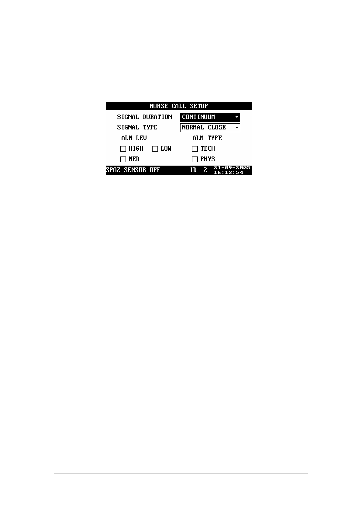
4.2.3 Nurse Call Setup
In the SYSTEM SETUP menu, select NURSE CALL. The NURSE CALL SETUP
menu appears, as shown in the following figure.
SIGNAL DURATION
Figure 4-5
1. CONTINUUM
It indicates that the nurse call signal duration is the same with the alarm duration,
namely, the nurse call signal lasts from the beginning of the alarm to the end of the
alarm.
2. PULSE
It indicates that the nurse call signal is a pulse signal whose duration is 1s. When
multiple alarms occur, the monitor outputs only one pulse signal; if another alarm
occurs before the current alarm is cleared, the monitor will output another pulse
signal.
SIGNAL TYPE
1. NORMAL CLOSE: set the signal type to NORMAL CLOSE when the nurse
call system of the hospital is set to normally-closed;
2. NORMAL OPEN: set the signal type to NORMAL OPEN when the nurse call
system of the hospital is set to normally-open.
ALM LEV: HIGH, MED, LOW; check box
ALM TYPE: TECH, PHYS; check box.
The system will send the nurse call signal according to the selected alarm level and
alarm type. If neither alarm level noralarm type is selected, the system will not send
any nurse call signal when alarms occur.
4-5
Page 52

Menus and Screens
CAUTION
z Then nurse call settings shall not be changed by non-medical staff.
NOTE
z The medical/nursing staff are not expected to take the nurse call
function as the major alarm notification. The patient conditions should
be determined based on the audible/visual alarm of the monitor and the
clinical symptoms of the patient.
z In the Alarm Paused or System Silenced status, the nurse call function
will be disabled.
4.2.4 Network Setup
In the SYSTEM SETUP menu, select NET SETUP. The NET SETUP menu appears,
as shown in the following figure.
NET TYPE: CMS, CMS+
LOCAL NET NO.: It indicates the bed number of a monitor in the
monitoring network. If the NET TYPE is CMS, the LOCAL NET NO can be
set between 1 and 64; if the NET TYPE is CMS+, it can not be set.
Figure 4-6
IP ADDRESS SETUP: When the monitor is connected with the central
monitoring system, and the NET TYPE is CMS+, you need to set the IP
address of your monitor .Set IP ADDDRESS SETUP in NET SETUP menu
The network type and local net No. are related to the central monitoring system
(CMS) to which the monitor is connected. Contact the CMS technical personnel of
Mindray or of the hospital for any doubt.
4-6
Page 53
4.2.5 Data Output
To output data,
1. Ensure the monitor is connected to the PC on which the Patient Information
Recall System software is running.
2. In the SYSTEM SETUP menu of the monitor, select DATA OUT, and then
Menus and Screens
press
3. If the connection is available, the data (including patient ID, patient type and
trend data of all patients) will be output to the PC. For more information, please
refer to the help information of the Patient Information Recall System software.
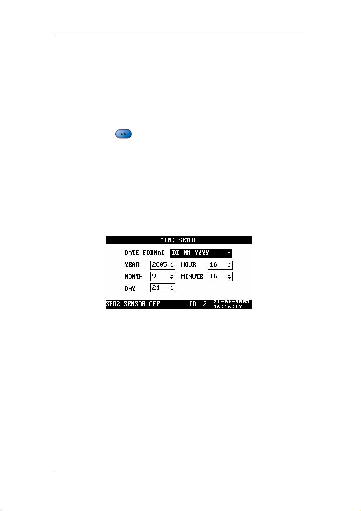
4.2.6 Time Setup
In the SYSTEM SETUP menu, select TIME SETUP. The TIME SETUP menu
appears, as shown in the following figure.
.
Figure 4-7
DATE FORMAT: You can set DATE FORMAT to any of the following
formats:
1. YY-MM-DD
2. MM-DD-YY
3. DD-MM-YY
Then, you can set the year, month, day, hour and minute respectively as required.
4-7
Page 54
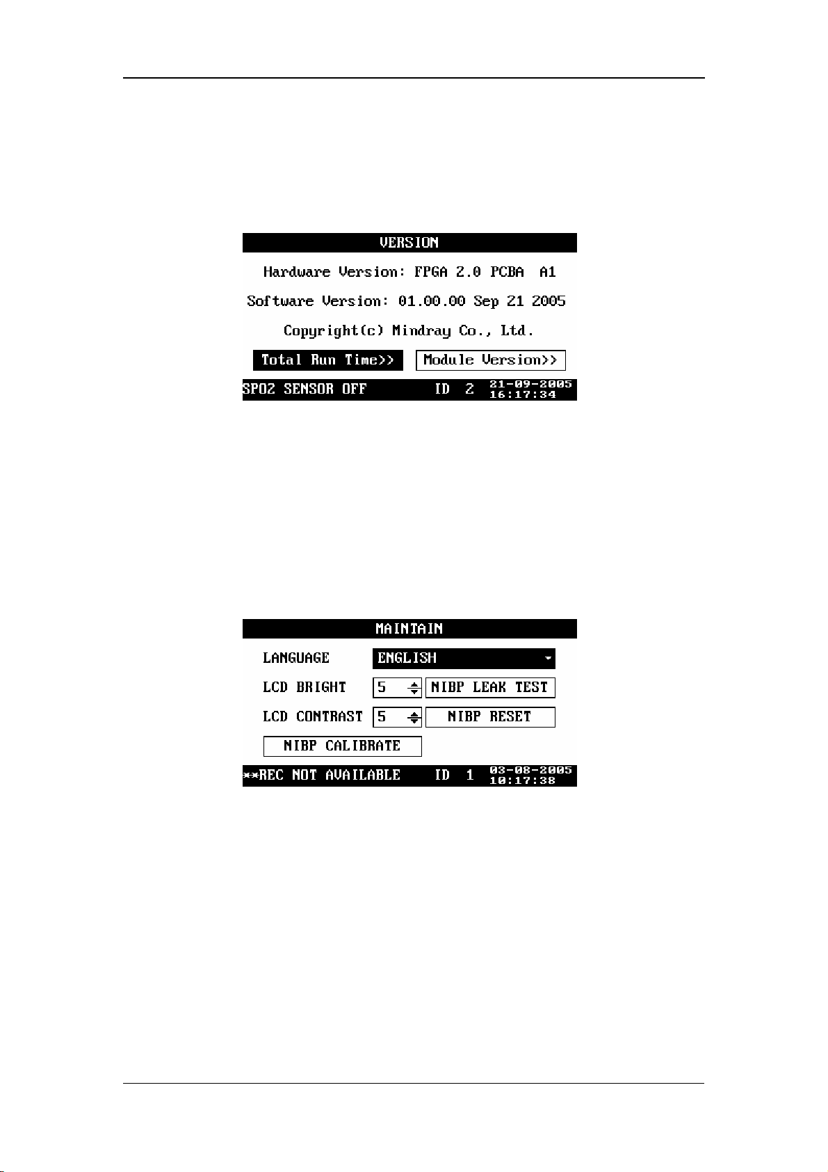
4.2.7 Version
In the SYSTEM SETUP menu, select VERSION, and then you can view the version
of the monitor, as shown in the following figure.
The information presented above may be different from that on your monitor. In this
case, take the version information on your monitor as standard.
Menus and Screens
Figure 4-8
4.2.8 Maintenance
In the SYSTEM SETUP menu, select MAINTAIN. The MAINTAIN menu appears,
as shown in the following figure.
In the MAINTAIN menu, you can set
LANGUAGE: set the language as required.
LCD BRIGHT: 1 - 10
LCD CONTRAST: 1 - 10
Figure 4-9
NIBP RESET: used to reset the NIBP module;
NIBP CALIBRAE: used to calibrate the NIBP module;
NIBP LEAK TEST: used to test the NIBP module for air leakage.
For details about the NIBP reset, NIBP calibration and test for air leakage, refer to 9
NIBP Monitoring.
4-8
Page 55

4.3 Alarm Setup
Press on the front panel of the monitor. The SET ALARMS menu appears,
Menus and Screens
as shown in the following figure. In this menu, you can set the NIBP and SpO
2
alarm switches as well as the corresponding upper and lower alarm limits.
Figure 4-10
By setting the alarm switch on the right of SYS ALM to ON/OFF, you can enable or
disable the physiological alarm for the NIBP measurement. By setting the alarm
switch on the right of SpO
physiological alarm for the SpO
ALM to ON/OFF, you can enable or disable the
2
measurement.
2
HI indicates the upper alarm limit, and LO indicates the lower alarm limit.
Move the cursor to HI/LO, and then press
, and to set the
upper alarm limit and lower alarm limit for each parameter.
When an NIBP value goes beyond the set upper/lower alarm limit, it will trigger the
alarm. The ranges of alarm limits are listed below:
Patient type Adult Pediatric Neonate
Systolic pressure 40 - 270 mmHg 40 - 200 mmHg 40 - 135 mmHg
Mean pressure 20 - 230 mmHg 20 - 165 mmHg 20 - 110 mmHg
Diastolic pressure 10 - 210 mmHg 10 - 150 mmHg 10 - 100 mmHg
When an SpO
/PR value goes beyond the set upper/lower alarm limit, it will trigger
2
the alarm. The ranges of alarm limits are listed below:
module type SpO2 PR
SpO
2
Mindray 0 – 100% 0 - 254 bpm
Masimo 0 - 100% 0 - 240 bpm
Nellcor 0 - 100% 0 - 250 bpm
4-9
Page 56

Menus and Screens
4.4 Trend Data Screen
The trend data screen is the default screen after the start-up. It displays the systolic
pressure (S), diastolic pressure (D) and mean pressure (M) of the NIBP monitoring
as well as the SpO
and PR. As shown in the following figure.
2
Figure 4-11
Press
dialog box appears. As shown in the following figure. In this dialog box, select
CURRENT ITEM, ITEMS OF CURRENT ID, or ITEMS OF ALL ID and then
select YES to delete the current trend data, all trend data of current ID, or data of all ID.
or to select a trend data, and then press . The DELETE
Figure 4-12
4-10
Page 57
Menus and Screens
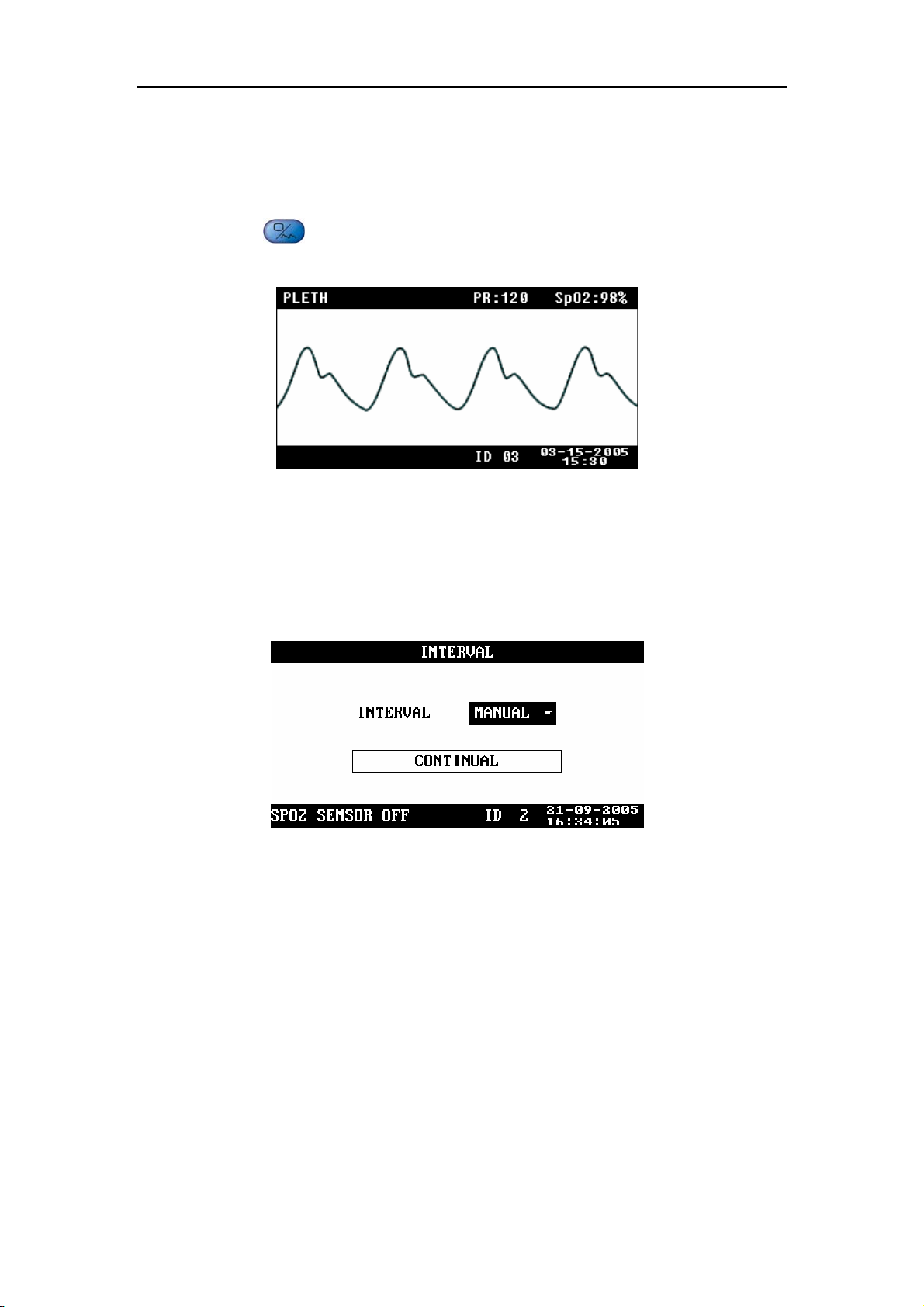
4.5 PLETH Waveform Screen
Press on the front panel of the monitor to display the PLETH waveform
screen, as shown in the following figure.
Figure 4-13
4.6 INTERVAL
INTERVAL: MANUAL, 1/2/3/4/5/10/15/30/60/90/120/180/240/480MIN
CONTINUAL: The monitor performs the NIBP measurements
continuously for five minutes.
Figure 4-14
Once INTERVAL is set to a value other than MANUAL, the monitor will starts an
auto NIBP measurement based on the selected interval.
4-11
Page 58

Menus and Screens
4.7 Standby State
4.7.1 Entering the Standby State
Press for less than 2 seconds. The CONFIRM STANDBY STATE dialog box
appears prompting “Enter the Standby State. Yes?” Select YES to enter the standby
state.
Figure 4-15
4-12
Page 59

Menus and Screens
4.7.2 Exiting the Standby State
In the Standby state, press any key on the front panel of the monitor. The EXIT
STANDBY dialog box appears prompting “Enter monitoring state?” Select YES to
exit the Standby state and enter the monitoring state. If no operation is done within
30 seconds, the monitor will automatically select NO, this dialog box will disappear,
and the monitor will keep in the Standby state.
Figure 4-16
The monitor exits the standby state and enters the monitoring state automatically
when
The monitor receives SpO
The probe is withdrawn from the probe sheath.
The monitor is powered by the internal battery which is to be depleted.
In the latter condition, the monitor prompts “BAT. VOLTAGE LOW” after
entering the monitoring status.
physiological signal for 5 seconds or more.
2
4-13
Page 60

FOR YOUR NOTES
Menus and Screens
4-14
Page 61

5 Alarms
5.1 Overview..................................................................................................... 5-2
5.1.1 Alarm Categories........................................................................... 5-2
5.1.2 Alarm Levels................................................................................. 5-3
5.2 Alarm Modes............................................................................................... 5-4
5.2.1 Visual Alarms................................................................................ 5-4
5.2.2 Audible Alarms ............................................................................. 5-4
5.2.3 Alarm Messages ............................................................................ 5-5
5.3 Alarm Status................................................................................................ 5-5
5.3.1 Alarms Disabled............................................................................ 5-5
5.3.2 Alarms Paused............................................................................... 5-6
5.3.3 System Silenced ............................................................................ 5-6
5.3.4 Status Switchover.......................................................................... 5-7
5.4 Clearing Alarms .......................................................................................... 5-8
5.5 When an Alarm Occurs............................................................................... 5-9
5-1
Page 62

Alarms
5.1 Overview
The monitor gives audible or visual alarms to indicate the medical staff, when a vital
sign of the patient appears abnormal, or mechanical or electrical problems occur to
the monitor.
NOTE
z For details about alarm setup of this monitor, please refer to 4.3 Alarm
Setup.
5.1.1 Alarm Categories
By nature, the alarms are divided into three categories: physiological alarms,
technical alarms and prompt information.
1. Physiological alarms
A physiological alarm either indicates that a monitored physiological parameter goes
beyond specified limits or indicates an abnormal patient condition. For example, no
pulse is detected.
2. Technical alarms
A technical alarm indicates that the monitor or parts of the monitor is not capable of
accurately monitoring the patient’s condition due to improper operation or system
failure. Technical alarms are also referred to as system error messages. For example,
an error occurs in the module initialization.
3. Prompt information
Strictly speaking, prompt information cannot be counted in alarms. It is usually
information relating to the system, but not concerning vital signs of patients. For
example, the monitor prompts “REC INITIALIZING”.
5-2
Page 63

5.1.2 Alarm Levels
By severity, the alarms of this monitor are divided into three priority levels: high
level alarms, medium level alarms and low level alarms.
1. High level alarms
The patient is in danger and requires emergency treatment, or
A serious technical problem occurs to the monitor, such as an error in the NIBP
module self-test.
2. Medium level alarms
Vital signs of the patient become abnormal, and patient requires immediate
treatment, or
Alarms
A specific technical problem occurs to the monitor, such as the leakage in the
NIBP hose.
3. Low level alarms
A specific technical problem occurs to the monitor, for example, the SpO
signal is too weak during the measurement.
The levels of all technical alarms and some physiological alarms are not
user-adjustable, because they have been fixed when the monitor is produced.
All physiological alarms, technical alarms and prompt information are given in
Appendix C Alarm Messages and Prompt .
2
5-3
Page 64

5.2 Alarm Modes
When an alarm occurs, the monitor raises the user’s attention by the following
audible or visual indications.
Visual alarms
Audible alarms
Alarm messages
Besides, the visual alarms, audible alarms and alarm messages are given in different
ways to identify different alarm levels.
5.2.1 Visual Alarms
Alarms
The alarm indicator on the front panel of the monitor varies its flash color and
frequency to indicate different alarm levels.
High level alarm: red and quick flash.
Medium level alarm: yellow and slow flash.
Low level alarm: yellow light without flash.
5.2.2 Audible Alarms
The monitor uses different alarm tones to indicate different alarm levels.
High level alarm: “DO-DO-DO--DO-DO---DO-DO-DO--DO-DO”.
Medium level alarm: “DO-DO-DO”.
Low level alarm: “DO”.
Different intervals correspond to different alarm levels: High level alarm phonates
once every 3 or 8 seconds. Medium level alarm phonates once every 14 or 24
seconds. Low level alarm phonates once every 24 seconds.
5-4
Page 65

5.2.3 Alarm Messages
Alarm messages are given when alarms occur. The alarm messages are displayed in
the physiological alarms area or the technical alarms area in black. For physiological
alarms, asterisks are displayed before the alarm messages to identify the alarm level.
High level alarms: triple asterisks “***”
Medium level alarms: dual asterisks “**”
Low level alarms: single asterisk “*”
5.3 Alarm Status
When an alarm occurs, normally the monitor gives indications in the modes
mentioned above as per the alam level. If necessary, you can set the monitor to the
following alarm status.
Alarms
Alarms Disabled
Alarms Paused
System Silenced
5.3.1 Alarms Disabled
If the alarm switch of a parmater is set to OFF, the monitor does not generate alarms
even if the measured parameter value exceeds the alarm limit. This status is called
Alarms Disabled.
To disable the alarms of a parameter, you need to open SET ALARMS menu .Take
NIBP (Non-Invasive Blood Pressure) as an example.
1. Press
2. Move the cursor to the pane to the right of SYS ALM.
to open the SET ALARMS menu.
3. Press
4. Select OFF, and press
parameter.
, and then press or .
to disable the alarm switch for the NIBP
5-5
Page 66

5.3.2 Alarms Paused
To suspend all alarms of the monitor, the duration of the alarm pause is fixed to 2
Alarms
minutes, press
Paused status,
Visual alarms and audible alarms are all suspended.
Alarm messages are not displayed.
The alarm message area shows the rest time of alarms paused status.
When the alarms paused time expires or a new technical or physiological alarm
occurs within the Alarms Paused time, the monitor will terminate the Paused Alarm
status and return to normal status. Besides, you can also manually termiante the
Alarms Paused status by pressing
on the front panel once (for less than 2 seconds). In Alarms
5.3.3 System Silenced
To silence the system, press for 2 seconds or more. In the System Silenced
status, all system sounds are shielded. However, other modes of alarms (excluding
audible alarms) are given as normal. A new technical or physiological alarm will
terminate the System Silenced status. The system sounds include the audible alarms,
key tones and pulse tones.
once.
5-6
Page 67

5.3.4 Status Switchover
In the Normal status,
Alarms
Press
Paused status, or
Press
Silenced status.
In the Alarms Paused statuses,
Press for less than 2 seconds to switch the monitor to the Normal status,
or
Press
Silenced status.
When the Alarm Paused time expires, the system will automatically switch to
the Normal status.
Within the Alarm Paused time, when a new technical or physiological alarm
occurs, the system will automatically switch to the Normal status.
for less than 2 seconds to switch the monitor to the Alarms
for 2 seconds or more to switch the monitor to the System
for 2 seconds or more to switch the monitor to the System
In the System Silenced status,
Press
Paused status, or
Press
When a new technical/physiological alarm occurs, the system will
automatically switch to the Normal status.
for less than 2 seconds to switch the monitor to the Alarms
for 2 seconds or more to switch the monitor to the Normal status.
5-7
Page 68

5.4 Clearing Alarms
1. Clearing audible and visual alarm indications
For a specific technical alarm, the audible and visual alarm indications will be
Alarms
cleared if the monitor is set to the Alarms Paused status (by pressing
than 2 seconds) and the alarm message will be changed to prompt information
during and after the alarms paused time. If the technical alarm is triggered again
after the monitor restores to the normal status, the monitor will give alarm
indications as normal.
For technical alarms whose audible and visual indications can be cleared, refer to
Appendix C Alarm Messages and Prompt .
2. Clearing all alarm indications
For a specific technical alarm, if the monitor is set to the Alarms Paused status (by
pressing
during and after the alarms paused time. If the technical alarm is triggered again
after the monitor restores to the normal status, the monitor gives alarm indications as
normal.
for less than 2 seconds), all alarm indications will be cleared
for less
5-8
Page 69

Alarms
5.5 When an Alarm Occurs
WARNING
z When an alarm occurs, always check the patient’s condition first.
When an alarm occurs to the monitor, refer to the following steps and take action
properly.
1. Check the patient’s condition.
2. Identify the alarming parameter and the alarm category.
3. Identify the cause of the alarm.
4. Take action to remedy the alarm cause.
5. Check if the alarm is cleared.
NOTE
z For details about how to deal with specific alarms, refer to Appendix C
Alarm Messages and Prompt .
5-9
Page 70

FOR YOUR NOTES
Alarms
5-10
Page 71

6 Recording
6.1 Overview..................................................................................................... 6-2
6.2 Recorder Operations.................................................................................... 6-2
6.3 Installing Recorder Paper ............................................................................ 6-3
6-1
Page 72

Recording
6.1 Overview
A thermal recorder is to be installed on the left side panel of the monitor. The
recorder is capable of printing:
Real-time PLETH waveforms.
Current displayed trend data.
All trend data of the current patient.
6.2 Recorder Operations
To print a real-time PLETH waveform
1. Press to open the PLETH waveform screen.
2. Press
waveform.
for less than 2 seconds to print the current displayed PLETH
To print current displayed trend data
1. Enter the trend data screen.
2. Press
for less than 2 seconds to print the current displayed trend data.
To print all trend data of the current patient
1. Enter the trend data screen.
2. Press
for 2 seconds or more to print all trend data of the current patient.
NOTE
z You can stop the printing at any time by pressing .
z For the recorder status information and the corresponding handling
measures, refer to Appendix C Alarm Messages and Prompt .
6-2
Page 73
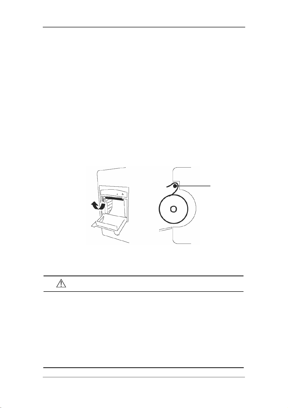
Recording
6.3 Installing Recorder Paper
Installing Procedure
1. Press the latch at the upper right of the paper compartment door to release the
door.
2. Lift the roller lever located at the upper left of the paper compartment, as
shown in the following figure.
3. Install a new roll of recorder paper into the compartment, as shown in the
following figure.
4. The roller of the recorder scrolls automatically, and the paper comes out of the
compartment.
5. Push down the roller lever.
6. Close the recorder door.
Roller
Figure 6-1 Installing Recorder Paper
CAUTION
z Use the thermal recorder paper specified by Mindray only. Other
recorder paper may cause the recorder to print with poor quality,
function improperly or not at all, or bring damage to the thermal print
head.
z Do not pull the recorder paper with force when the printing is in
process. Otherwise, damages to the recorder may be incurred.
z Do not leave the recorder door open except when you are replacing the
recorder paper or removing a fault.
6-3
Page 74

Removing the Paper Jam
If the recorder does not function properly or produces unusual sound, check whether
there is a paper jam. If yes, remove it in the following procedure:
1. Open the recorder door.
2. Tear the paper off from the leading edge at the paper outlet.
3. Lift the lever on the upper left of the recorder.
4. Pull the paper from the paper inlet.
5. Re-install the paper.
Recording
6-4
Page 75

7 Management System Software
7.1 Installation and Uninstallation .................................................................... 7-3
7.1.1 Installing the PV Software ............................................................ 7-3
7.1.2 Uninstalling the PV Software........................................................ 7-5
7.1.3 Network Connection ..................................................................... 7-5
7.2 Main Window.............................................................................................. 7-6
7.2.1 Menu Bar....................................................................................... 7-6
7.2.2 Patient Management...................................................................... 7-7
7.3 Software Functions...................................................................................... 7-8
7.3.1 Trend Review ................................................................................ 7-8
7.3.2 NIBP Review ................................................................................ 7-10
7-1
Page 76

Management System Software
The Prsview management system software (PV software as referred to hereinafter)
is optional for the VS-800 Vital Signs Monitor. It is used in conjuction with the
VS-800 system software and implements the following functions:
Data output and software upgrade.
Display of output data.
Addition/modification of patient information.
Data printing.
7-2
Page 77

Management System Software
7.1 Installation and Uninstallation
7.1.1 Installing the PV Software
The PV software supports Windows 98/2000/XP operating system (Chinese/English
Edition). In this operation manual, the installation of the PV software is introduced
with an example of installation under the Windows 2000 operating system.
1. Insert the installation disk into the CD driver.
2. Run the Setup.exe file in the installation disk. Then the following dialog box
appears.
3. In this dialog box, click Next. Then the following dialog box appears.
7-3
Page 78

Management System Software
4. In this dialog box, click Next. Then the following dialog box appears.
5 Click Finish.
Once the installation is finished, a PrsView short-cut icon will appear on the desktop,
and the shortcut will appear in the Start menu.
7-4
Page 79

Management System Software
7.1.2 Uninstalling the PV Software
To uninstall the PV software, follow the procedure below:
1. Click the Start menu, and select Control Panel-Add/Delete Program.
2. In the Add/Delete Program dialog box, select PrsView, and then click Delete to
uninstall the PV software.
Note
z The procedures above are for reference only. The installation or
uninstallation procedures may different in different operating systems.
7.1.3 Network Connection
Before operation, you need to connect the PC and the monitor with a cross-type
network cable, then run the Prsview software.
In the SYSTEM SETUP menu of the monitor, select NET SETUP, and then set NET
TYPE to CMS or CMS+.
For CMS, set the IP address of the PC to 202.114.4.119.
For CMS+, set the IP address of the PC to a value among where the first three
domains are the same with that of the IP address of the monitor and the last
domain is different from that of the IP address of the monitor.
7-5
Page 80
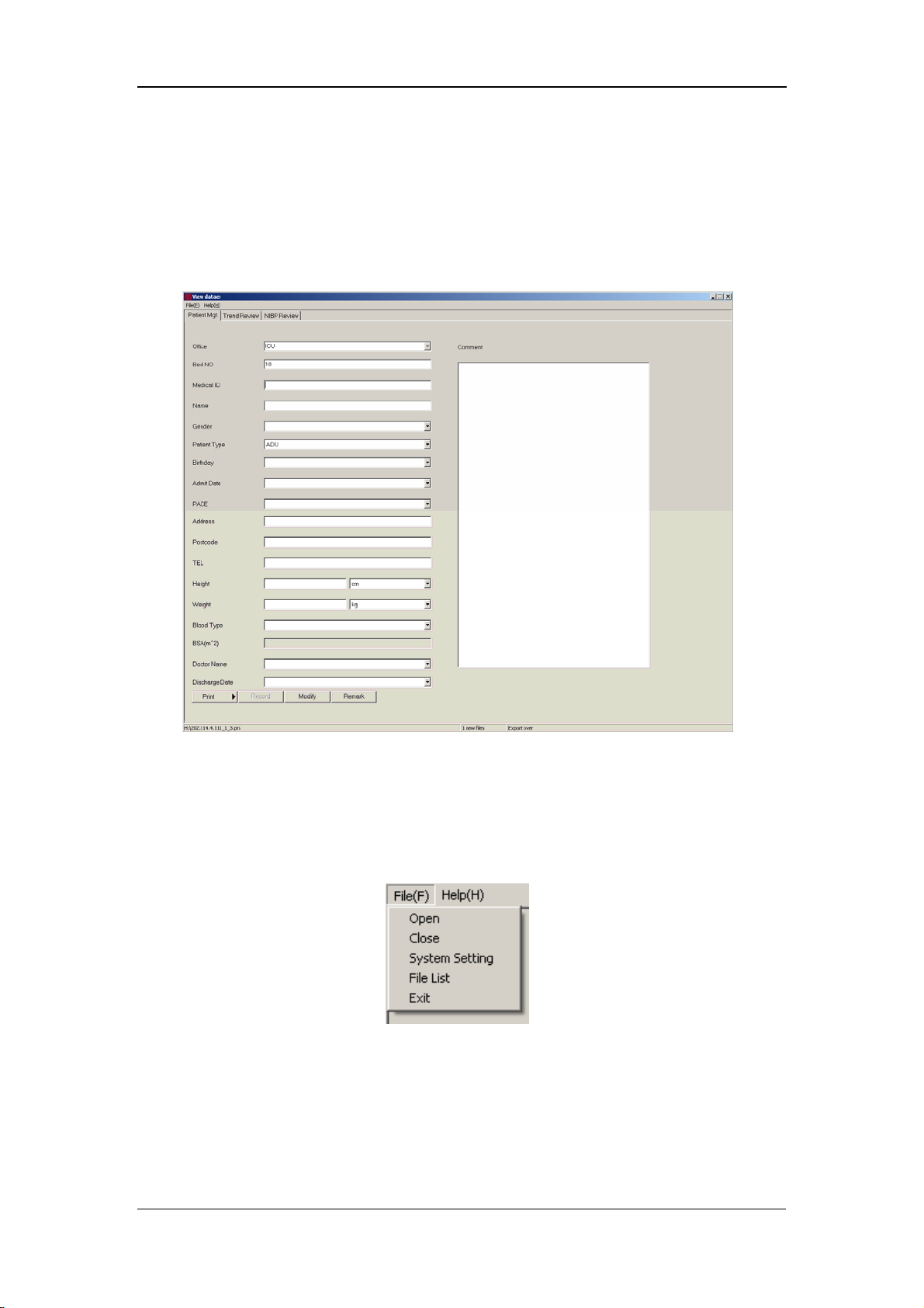
Management System Software
7.2 Main Window
Click the PV software in the Start menu. The main window shown in the following
figure appears.
7.2.1 Menu Bar
Click File in the menu bar. The File pull-down menu appears, as shown in the
following figure.
Open: to open thefile dialog box.
Close: to close the file dialog box.
System setting: to modify the color and unit of the module, as shown in
Figure 7-1
Figure 7-1
7-6
Page 81

Management System Software
File List: same as Open.
Exit: to exit the current application.
Figure 7-1
7.2.2 Patient Management
In the Patient Management tab, you can enter the following information:
Department: to be selected from the drop-down list box.
Bed No.: to be entered; Range: 1 – 99.
Patient No.: composed of English letters and/or numerals, maximum
characters: 12.
Name: up to 12 characters for English letters, or up to 12
Chinese characters.
Sex: male or female.
Patient Type: to be selected from the drop-down list box.
Birthday: to be selected from the drop-down list box.
Admit Date: to be selected from the drop-down list box.
Pace: to be selected from the drop-down list box.
Address: patient address, to be entered.
Post Code: up to 12 numerals can be entered.
Telephone: up to 24 numerals can be entered.
Height: to be entered per either of the two optional units.
Weight: to be entered per either of the two optional units.
Blood Type: to be selected from the drop-down list box.
7-7
Page 82
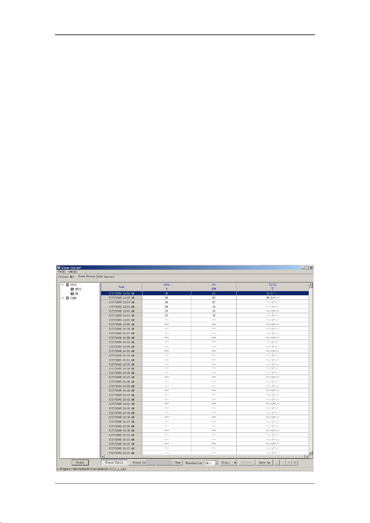
Management System Software
Body Surface Area: to be obtained and displayed automatically based on the
entered height and weight.
Doctor: up to 12 characters for English letters, or up to 12
Chinese characters.
Discharge Date: to be selected from the drop-down list box.
Diagnosis: Result: to be entered by doctor.
Print: the patient data within the set ID range can be printed.
Record: to record data.
Modify: to save the currently set information.
Additional: to supplement patient information.
7.3 Software Functions
7.3.1 Trend Review
In the Main Window, select the Trend Review tab. The SpO
reviewed in the Trend Review tab, as shown in the following figure:
and PR data can be
2
7-8
Page 83

Management System Software
Order: to enter the Set up parameter order dialog box. See the
following figure.
Trend Graph: to display the SpO
and PR data, see the following figure.
2
Set Start Time: to enter the Please input Start Time dialog box, see the
following figure.
7-9
Page 84
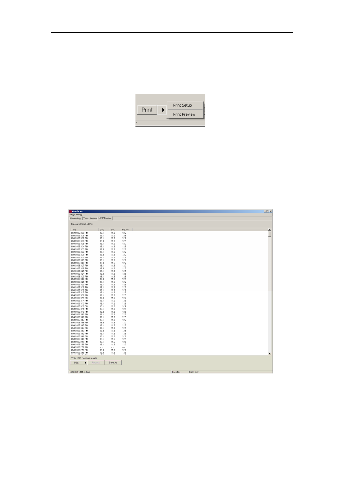
Resolution to select the resolution from the drop-down list box. Options: 1Min,
5Min, 15Min, 30Min and 60Min.
Print: to print data directly or to access Print Setup or Print
Preview by clicking the arrow on the right of the Print button. See the
following figure.
Save As: to save data into a file.
7.3.2 NIBP Review
In the Main Window, select the NIBP Review tab. The measured NIBP results can
be reviewed in the NIBP Review tab, as shown in the following figure.
Management System Software
7-10
Page 85

8 SpO
8.1 Mindray SpO
8.2 Masimo SpO
8.3 Nellcor SpO
Monitoring
2
Module ................................................................................ 8-3
2
8.1.1 Principles of Operation.................................................................. 8-3
8.1.2 Precautions .................................................................................... 8-3
8.1.3 Monitoring Procedure ................................................................... 8-4
8.1.4 Measurement Limitations.............................................................. 8-7
Module................................................................................. 8-9
2
8.2.1 Principles of Operation.................................................................. 8-9
8.2.2 Precautions .................................................................................. 8-12
8.2.3 Monitoring Procedure ................................................................. 8-13
8.2.4 Measurement Limitations............................................................ 8-13
8.2.5 Masimo Information.................................................................... 8-15
Module................................................................................ 8-16
2
8.3.1 Principles of Operation................................................................ 8-16
8.3.2 Precautions .................................................................................. 8-19
8.3.3 Monitoring Procedure ................................................................. 8-20
8.3.4 Measurement Limitations............................................................ 8-20
8.3.5 Nellcor Information....................................................................... 8-22
8-1
Page 86

SpO2 Monitoring
This monitor can be equipped with any of the following SpO
modules:
2
Mindray SpO
Masimo SpO
Nellcor SpO
module
2
module
2
module.
2
A monitor, equipped with a Masimo or Nellcor SpO
module, is marked by
2
"Masimo" or "Nellcor" at the lower left corner of the front panel. The following
pages respectively gives introduction to the above three SpO
modules. Please read
2
this chapter according to your monitor configuration before operation.
8-2
Page 87

SpO2 Monitoring
8.1 Mindray SpO2 Module
NOTE
z This section is only applicable to the monitor equipped with a Mindray
module.
SpO
2
8.1.1 Principles of Operation
The oxygen saturation (SpO
a continuous, non-invasive method based on the different absorption spectra of
reduced hemoglobin and oxyhemoglobin. It measures how much light, sent from
light sources on one side of the sensor, is transmitted through patient tissue (such as
a finger or an ear), to a receiver on the other side. The amount of light transmitted
depends on many factors, most of which are constant. However, one of these factors,
the blood flow in the arteries, varies with time regularly, because it is pulsating. By
measuring the light absorption during a pulsation, it is possible to calculate the
oxygen saturation of the arterial blood. Detecting the pulsation gives a PLETH
waveform and pulse rate value.
The sensor measurement wavelengths are nominally 660nm for the red LED and
940nm for infrared LED. The maximum optical power output for LED is 4 mW.
) is measured with a method called pulse oximetry. It is
2
8.1.2 Precautions
WARNING
z The SpO2 value can be overestimated in the presence of Hb-CO, Met-Hb
or dye dilution chemicals.
z Check if the sensor is in normal condition before monitoring. Do not
use the SpO
z After unplugging the SpO
monitor, the system shall display the alarm message "SPO2 SENSOR
OFF" and give the audible alarm.
sensor once the package or the sensor is found damaged.
2
sensor cable from the connector of the
2
8-3
Page 88

SpO2 Monitoring
z ES (Electrosurgery) equipment wire and SpO2 cable must not be
tangled up.
z Do not put the SPO
sensor on extremities with arterial catheter or
2
venous syringe.
z Do not perform SpO
monitoring and NIBP measurements on the same
2
limb simultaneously. Obstruction of blood flow during NIBP
measurements may adversely affect the SpO
reading.
2
z During prolonged and continuous monitoring, check the sensor
placement regularly to ensure proper attachment, and move to another
location if the skin deteriorates. More frequent examinations may be
required for different patients, like neonates and patients of poor
perfusion or skin sensitive to light.
NOTE
z SpO2 waveform is not proportional to the pulse volume.
8.1.3 Monitoring Procedure
Sensor selection for the SpO
patient, you can choose a finger SpO
hand or toe sensor. Perform SpO
1. Power on the monitor.
2. Attach the sensor to the proper site on the patient.
3. Plug the connector of the sensor extension cable into the SpO
monitor.
measurement depends on the patient type. For an adult
2
measurements in the following procedure.
2
sensor; for an infant patient, you can choose a
2
connector on the
2
8-4
Page 89

Finger Sensor Placement
You can easily place the finger sensor as shown below.
Figure 8-1 Finger Sensor Placement
SpO2 Monitoring
NOTE
z Place the SpO2 sensor cable at the backside of the patient hand. Make
sure the fingernail is just opposite to the light emitted from the sensor.
Neonate Sensor Placement
Neonate SpO
LED and PD ends of the Y-shape SpO
grooves on the sheath (See Figure 8-2). Figure 8-3 shows the neonate SpO
after inserted.
Y-shape sensor Neonate sensor sheath
sensor consists of a Y-shape SpO2 sensor and its sheath. Insert the
2
sensor respectively into the upper and lower
2
sensor
2
Figure 8-2 Neonate Sensor Placement (1)
8-5
Page 90

SpO2 Monitoring
Figure 8-3 Neonate Sensor Placement (2)
Wind the SpO
sensor around the hand or foot of a neonate patient. Hold the sensor,
2
pull the belt and fit one of its sides with “V” edge into the “V” groove on the
corresponding side of the sheath. Appropriately elongate the belt to about 20mm,
and fit the “V” edge of the other side of the belt into the “V” groove of the other side
of the sheath. Then, loosen the belt. After the “V” edges of the two sides of the belt
fit well into the “V” grooves on the two sides of the sheath, put the belt into the first
lock bar to fasten the belt. See the following figure. If the belt is too long, you may
put it into the second lock bar. You must position the SpO
sensor in this way so as
2
to make the photoelectric component face the correct position. Besides, remember
not to elongate the belt too much, which may lead to inaccurate measurement and
block the blood circulation severely.
Figure 8-4 Neonate Sensor Placement (3)
8-6
Page 91

SpO2 Monitoring
NOTE
z If the sensor cannot be positioned accurately to the part to be
measured, it may result in inaccurate SpO
cannot be measured because no pulse is detected. In this case, you
must position the sensor again.
z Excessive patient movements may result in inaccurate readings. In this
case, you must keep the patient quiet or change the measured position
to reduce the adverse influence of excessive movement.
reading, or the SpO2 even
2
WARNING
z In the process of extended and continuous monitoring, you should
check the peripheral circulation and the skin every 2 hours. If any
unfavorable change takes place, you should change the measured
position in time.
z In the process of extended and continuous monitoring, you should
periodically check the position of the sensor. In case that the position
of the sensor moves during monitoring, the measurement accuracy
may be affected.
8.1.4 Measurement Limitations
If the accuracy of any measurement does not seem reasonable, first check the
patient’s vital signs with an alternate method, and then check the monitor and the
sensor.
Inaccurate measurements may be caused by:
Incorrect sensor application or use.
High-frequency electrical noise, including the noise generated by the monitor,
or the noise from external sources, such as electrosurgical apparatus connected
to the system.
Oximeters and oximetry sensors used during magnetic resonance imaging
(MRI) scanning (Induced current may cause burns).
Intravascular dye injections.
8-7
Page 92

SpO2 Monitoring
Excessive patient motion.
Excessive ambient light.
Improper sensor installation or incorrect sensor placement on the patient.
Sensor temperature (optimal temperature range: 28 ℃ - 42 )℃ when exceeded.
The factor that the sensor is placed on a limb that is attached to an NIBP cuff,
arterial catheter, or intravascular line.
Concentration of dysfunctional hemoglobin, such as carboxyhemoglobin
(COHb) and methemoglobin (MetHb).
SpO
too low.
2
Low circular perfusion of the applied part.
Shock, anemia, low temperature and application of vasomotor which reduce the
arterial blood flow to such a degree that the SpO
measurement cannot be
2
performed.
The absorption of oxyhemoglobin (HbO
special wavelength may also affect the accuracy of the SpO
) and deoxyhemoglobin to the light of
2
measurement. If there
2
are other substances (such as carbon hemoglobin, methemoglobin, methylene blue
and indigo carmine) absorbing the light of the same wavelengths, they may result in
false or low SpO
readings.
2
8-8
Page 93

SpO2 Monitoring
=
8.2 Masimo SpO2 Module
NOTE
z This section is only applicable to the monitor equipped with a Masimo
module.
SpO
2
8.2.1 Principles of Operation
The pulse oximetry measurement module (Masimo Set
Oxyhemoglobin and deoxyhemoglobin differ in their absorption of red and
infrared light (spectrophotometry).
) is based on three principles:
The volume of arterial blood in tissue and the light absorbed by the blood
changes during the pulse (plethysmography).
Arterio-venous shunting is highly variable, and the fluctuating absorbance by
venous blood is a major component of noise during the pulse.
The working principle of Masimo Set uses is similar to the traditional SpO
It calculates the SpO
measuring changes in light absorption during the pulsatile cycle. The red and
infrared light-emitting diodes (LEDs) in oximetry sensors serve as the light sources,
and the photodiode serves as the photodetector.
Traditional pulse oximeter assumes that all pulsations in the light absorbance signal
are caused by oscillations in the arterial blood volume. This assumes that the blood
flow in the region of the sensor passes entirely through the capillary bed rather than
through any arterio-venous shunts. The traditional pulse oximeter calculates the ratio
of pulsatile absorbance (AC) to the mean absorbance (DC) at each of two
wavelengths, 660 nm and 940 nm:
value by passing red and infrared light into a capillary bed and
2
module.
2
)660(/)660()660(Re DCACd =
)940(/)940()940( DCACIr
This traditional instrument then calculates the ratio of these two arterial pulse-added
absorbance signals:
)940(/)660(Re IrdR =
This value of R is used to find the SpO
in a look-up table built into the instrument’s
2
8-9
Page 94

SpO2 Monitoring
=
software. The values in the look-up table are based upon human blood studies
against a laboratory co-oximeter on healthy adult volunteers in induced hypoxia
studies.
This Masimo Set assumes that arterio-venous shunting is highly variable and that
fluctuating absorbance by venous blood is the major component of noise during the
pulse. The Masimo Set decomposes S (660) and S (940) into an arterial signal plus a
noise component and calculates the ratio of the arterial signals without the noise:
NrSrd +=)660(Re
)940(
NiSiIr +
SiSrR /=
Again, R is the ratio of two arterial pulse-added absorbance signals and its value is
used to find the saturation SpO
The values in the empirically derived equation are based upon human blood studies
against a laboratory co-oximeter on healthy adult volunteers in induced hypoxia
studies.
in an empirically derived equation into the software.
2
8-10
Page 95

SpO2 Monitoring
×
The above equations are combined and a noise reference (N’) is determined:
−= )940()660(Re'
RIrdN
When the noise reference (N’) is 0,
RIrd ×= )940()660(Re
The equation for the noise reference is based on the value of R, the value being
seeked to determine the SpO
values of R that corresponds to SpO
N’ value for each of these R values. The S (660) and S (940) signals are processed
with each possible N’ noise reference through an adaptive correlation canceler (ACC)
which yields an output power for each possible value of R (i.e., each possible SpO
from 1% to 100%). The result is a Discrete Saturation Transform (DST™) plot of
relative output power versus possible SpO
where R corresponds to SpO
Discrete Saturation Transform DSTTM
. The Masimo Set’s software sweeps through possible
2
values between 1% and 100% and generates an
2
value as shown in the following figure
2
= 97%:
2
2
Emergy Output
Relative Correlation Canceler
The DST plot has two peaks: the peak corresponding to the higher saturation is
selected as the SpO
on the most recent four seconds of raw data. The SpO
to a running average of arterial hemoglobin saturation that is updated every two
seconds.
%
SpO
2
value. This entire sequence is repeated once every two seconds
2
value therefore corresponds
2
8-11
Page 96

SpO2 Monitoring
8.2.2 Precautions
WARNING
z The pulse wave from the Masimo Set SpO2 module should NOT be used
for apnea monitoring.
z As a trend towards patient deoxygenation is indicated, blood samples
should be analyzed by a laboratory co-oximeter to completely
understand the patient’s condition.
z Once an alarm has occurred, the system will resume the sound of the
silenced alarms (except for the special cases listed in this manual).
z Measure the monitor’s leakage current whenever an external device is
connected to the serial port. Leakage current must not exceed 100
microamperes.
z To ensure patient electrical isolation, connect only to other equipment
with electronically isolated circuits.
z Do not connect to an electrical outlet controlled by a wall switch or
dimmer.
z Carefully route patient cabling to reduce the possibility of patient
entanglement or strangulation.
z Interfering Substances: Carboxyhemoglobin may erroneously increase
readings. The level of increase is approximately equal to the amount of
carboxyhemoglobin present. Dyes, or any substance containing dyes,
that change usual arterial pigmentation may cause erroneous readings.
z Do not use this instrument and the sensors during magnetic resonance
imaging (MRI). Induced current could potentially cause burns. The
monitor may affect the MRI image, and the MRI unit may affect the
accuracy of the oximetry measurements.
z The SpO
value might be overestimated in the presence of Hb-CO,
2
Met-Hb or dye dilution chemicals.
z Verify sensor cable fault detection before beginning mon itoring. Unplug
the SpO
sensor cable from the connector. The screen displays the
2
error message “SPO2 SENSOR OFF” and the audible alarm is
activated.
z Do not use the supplied sterile SpO
sensors if the packaging or the
2
8-12
Page 97

SpO2 Monitoring
sensor is damaged. Return them to the vendor.
z Do not perform SpO
and NIBP measurements on the same limb
2
simultaneously. Obstruction of blood flow during NIBP measurements
may adversely affect the reading of the SpO
value.
2
z Prolonged and continuous monitoring may increase the risk of burns at
the site of the sensor. It is especially important to check the sensor
placement, and ensure proper attachment on neonates and patients of
poor perfusion or skin sensitive to light. Check the sensor location
every 2–3 hours and move it to another location if the skin deteriorates.
More frequent examinations may be required for different patients.
NOTE
z Place the SpO2 sensor cable at the backside of the patient hand. Make
sure the patient nail is just opposite to the light emitted from the
sensor.
z The SpO
value is not proportional to the pulse rate.
2
8.2.3 Monitoring Procedure
Follow the procedure below:
1. Power on the monitor.
2. Attach the sensor to the proper site on the patient.
3. Plug the connector of the sensor extension cable into the SpO
monitor.
The process of SpO
sensor selection and placement depend on the patient type. When choosing a
SpO
2
plethysmogram measurement is generally the same. But the
2
site for a sensor, refer to the directions for that sensor.
8.2.4 Measurement Limitations
If the accuracy of any measurement does not seem reasonable, first check the
patient’s vital signs by an alternate method and then check the monitor and the
sensor.
Inaccurate measurements may be caused by:
connector on
2
incorrect sensor application or use.
8-13
Page 98

SpO2 Monitoring
significant levels of dysfunctional hemoglobins (e.g., carboxyhemoglobin or
methemoglobin).
intravascular dyes such as indocyanine green or methylene blue.
exposure to excessive illumination, such as surgical lamps (especially ones
with a xenon light source), bilirubin lamps, fluorescent lights, infrared heating
lamps, or direct sunlight (exposure to excessive illumination can be corrected
by covering the sensor with a dark material).
excessive patient motion.
venous pulsations.
placement of a sensor on the same extremity with a blood pressure cuff, arterial
catheter, or intravascular line.
application during defibrillation, when, however, the readings may take a short
period of time to return to normal.
Loss of pulse signal can occur when
the sensor is too tight.
there is excessive illumination from light sources such as a surgical lamp, a
bilirubin lamp, or sunlight.
a blood pressure cuff is inflated on the same extremity as the one with an SpO
sensor attached.
the patient has hypotension, severe vasoconstriction, severe anemia, or
hypothermia.
there is arterial occlusion proximal to the sensor.
the patient is in cardiac arrest or is in shock.
2
8-14
Page 99

SpO2 Monitoring
8.2.5 Masimo Information
®
The MASIMO SET
Masimo Patents
This device is covered under one or more of the following U.S. Patents: 5,482,036;
5,490,505; 5,632,272; 5,685,299; 5,758,644; 5,769,785; 6,002,952; 6,036,642;
6,067,462; 6,206,830; 6,157,850 and international equivalents. U.S.A and
international patents pending.
Product
®
No Implied License
Possession or purchase of this device does not convey any express or implied license
to use the device with replacement parts which would, alone, or in combination with
this device, fall within the scope of one or more of the patents relating to this device.
8-15
Page 100

SpO2 Monitoring
8.3 Nellcor SpO2 Module
NOTE
z This section is only applicable to the monitor equipped with a Nellcor
module.
SpO
2
8.3.1 Principles of Operation
Bone, tissue, pigmentation, and venous vessels normally absorb a constant amount
of light over time. The arteriolar bed normally pulsates and absorbs variable
amounts of light during the pulsations. The monitor uses pulse oximetry to measure
functional oxygen saturation in the blood. Pulse oximetry works by applying a
sensor to a pulsating arteriolar vascular bed, such as a finger or toe. The sensor
contains a dual light source and a photodetector. The ratio of light absorbed is
translated into a measurement of functional oxygen saturation (SpO
).
2
Oximetry Overview
Pulse oximetry is based on two principles:
1. Oxyhemoglobin and deoxyhemoglobin differ in their absorption of red and
infrared light (i.e., spectrophotometry).
2. The volume of arterial blood in tissue (and hence, light absorption by that blood)
changes during the pulse (i.e., plethysmography).
A monitor determines SpO
by passing red and infrared light into an arteriolar bed
2
and measuring changes in light absorption during the pulsatile cycle. Red and
infrared low-voltage light-emitting diodes (LEDs) in the oximetry sensor serve as
light sources; a photodiode serves as the photo detector.
Because oxyhemoglobin and deoxyhemoglobin differ in light absorption, the
amount of red and infrared light absorbed by blood is related to hemoglobin oxygen
saturation. To identify the oxygen saturation of arterial hemoglobin, the monitor uses
the pulsatile nature of arterial flow. During systole, a new pulse of arterial blood
enters the vascular bed, and blood volume and light absorption increase. During
diastole, blood volume and light absorption reach their lowest point. The monitor
bases its SpO
measurements on the difference between maximum and minimum
2
absorption (i.e., measurements at systole and diastole). By doing so, it focuses on
8-16
 Loading...