

Page 1

M9/M9T/M9CV/M9GI/M9Vet
Diagnostic Ultrasound System
Service Manual(Advanced)
Revision 15.0
Page 2

Page 3

i
Table of Contents
Table of Contents ....................................................................................................................i
Version Information ................................................................................................................I
Intellectual Property Statement ...........................................................................................III
Applicability ..........................................................................................................................III
Responsibility of Mindray ....................................................................................................III
Warranty Statements ........................................................................................................... IV
Customer Service Department ............................................................................................ V
Descriptions Committed ...................................................................................................... V
1 Safety Precautions ..................................................................................................... 1-1
1.1 Meaning of Signal Words ..................................................................................................... 1-1
1.2 Symbols ................................................................................................................................ 1-1
1.2.1 Meaning of Safety Symbols .......................................................................................... 1-1
1.2.2 Warning Labels ............................................................................................................. 1-2
1.2.3 General Symbols .......................................................................................................... 1-2
1.3 Safety Precautions ............................................................................................................... 1-3
1.3.1 Electric Safety ............................................................................................................... 1-4
1.3.2 Mechanical Safety ........................................................................................................ 1-5
1.3.3 Personnel Safety .......................................................................................................... 1-5
1.3.4 Others ........................................................................................................................... 1-5
2 Product Specifications ............................................................................................... 2-1
2.1 Introduction ........................................................................................................................... 2-1
2.1.1 Intended Use ................................................................................................................ 2-1
2.1.2 System Appearance ..................................................................................................... 2-1
2.1.3 Trolley Appearance ..................................................................................................... 2-10
2.1.4 Peripherals Supported ................................................................................................ 2-13
2.2 Specifications ..................................................................................................................... 2-14
2.2.1 External Dimensions and Weight ............................................................................... 2-14
2.2.2 Electric Specifications ................................................................................................. 2-14
2.2.3 Environment Specifications ........................................................................................ 2-15
2.2.4 Monitor Specifications ................................................................................................. 2-15
3 System Installation ..................................................................................................... 3-1
3.1 Installation Preparations ....................................................................................................... 3-1
3.1.1 Electrical Requirements ................................................................................................ 3-1
3.1.2 Installation Condition .................................................................................................... 3-2
3.1.3 Installation Confirmation ............................................................................................... 3-2
3.2 Unpacking ............................................................................................................................ 3-2
3.2.1 Unpacking Process ....................................................................................................... 3-2
3.2.2 Check ............................................................................................................................ 3-7
3.3 Installation of Whole Device ................................................................................................. 3-7
3.3.1 Connecting Power Cable .............................................................................................. 3-7
3.3.2 Connecting ECG ........................................................................................................... 3-7
3.3.3 Connecting a Ultrasound Probe ................................................................................... 3-7
3.4 Installing Peripherals ............................................................................................................ 3-8
3.4.1 Connecting the Footswitch ........................................................................................... 3-8
Page 4

ii
3.4.2 Connecting/Removing a USB Memory Device ............................................................. 3-8
3.4.3 Graph/Text Printer......................................................................................................... 3-8
3.4.4 Video Printer ............................................................................................................... 3-10
3.4.5 Barcode Reader .......................................................................................................... 3-11
3.5 Wired Network Connection ................................................................................................ 3-14
3.6 System Configuration ......................................................................................................... 3-14
3.6.1 Power-on Running ...................................................................................................... 3-14
3.6.2 Enter Doppler .............................................................................................................. 3-14
3.6.3 System Preset ............................................................................................................ 3-15
3.6.4 Print Preset ................................................................................................................. 3-16
3.6.5 Network Preset ........................................................................................................... 3-17
3.6.6 Network Configure ...................................................................................................... 3-18
3.6.7 DICOM/HL7 Preset ..................................................................................................... 3-20
3.6.8 System Information Verification .................................................................................. 3-21
4 Product Principle ........................................................................................................ 4-1
4.1 General Structure of Main Unit’s Hardware System ............................................................ 4-1
4.2 Main Board ........................................................................................................................... 4-2
4.2.1 Power Supply ................................................................................................................ 4-3
4.2.2 Backend ........................................................................................................................ 4-3
4.2.3 Front-end of Main Board ............................................................................................... 4-5
4.3 TR64 Board .......................................................................................................................... 4-6
4.4 Probe Board ......................................................................................................................... 4-6
4.5 PHV Power Supply Board .................................................................................................... 4-7
4.6 ECG Unit .............................................................................................................................. 4-7
4.7 Control Panel ........................................................................................................................ 4-9
4.8 Main Display Unit ............................................................................................................... 4-10
4.9 Probe Extension Board ...................................................................................................... 4-11
4.10 Audio/Video Transfer Module ............................................................................................. 4-12
4.11 USB HUB Board ................................................................................................................. 4-13
4.12 Trolley Power Supply ......................................................................................................... 4-13
4.12.1 Connection Board of Trolley Power Supply ................................................................ 4-14
4.12.2 AC_DC Power Supply ................................................................................................ 4-14
4.12.3 Management Board of Trolley Battery ........................................................................ 4-14
4.13 System Power-on Control .................................................................................................. 4-15
4.14 Internal Connection Diagram of Main Unit and Trolley ...................................................... 4-17
4.15 Details in Main Unit’s Power-on ......................................................................................... 4-17
5 Checking Performance and Functions ..................................................................... 5-1
5.1 Description ........................................................................................................................... 5-1
5.2 Checking System Status ...................................................................................................... 5-1
5.2.1 Running Status ............................................................................................................. 5-1
5.2.2 Working Condition ........................................................................................................ 5-1
5.3 General Check ..................................................................................................................... 5-2
5.3.1 Check Flow ................................................................................................................... 5-2
5.3.2 Check Content .............................................................................................................. 5-2
5.4 Functions Checking .............................................................................................................. 5-5
5.4.1 Checking Flow .............................................................................................................. 5-5
5.4.2 Checking Content ......................................................................................................... 5-5
5.5 Performance Test ............................................................................................................... 5-12
5.5.1 Test Procedures .......................................................................................................... 5-12
5.5.2 Test Content ................................................................................................................ 5-12
Page 5

iii
6 Software Installation & Maintenance ........................................................................ 6-1
6.1 Enter Maintenance ............................................................................................................... 6-1
6.2 Software Installation/Restoration ......................................................................................... 6-2
6.3 Enter Windows ..................................................................................................................... 6-2
6.4 Software Maintenance .......................................................................................................... 6-2
6.4.1 Log Export .................................................................................................................... 6-2
6.5 Data Backup and Storage .................................................................................................... 6-3
6.5.1 Preset Data Management ............................................................................................. 6-3
6.5.2 Patient Data Backup and Restoration .......................................................................... 6-4
6.6 Introduction on HDD Partition Data ...................................................................................... 6-4
7 Field Replaceable Unit ............................................................................................... 7-1
7.1 Main Unit .............................................................................................................................. 7-2
7.2 Mobile Trolley ..................................................................................................................... 7-15
8 Structure and Assembly/Disassembly ...................................................................... 8-1
8.1 Structure of the Complete System ....................................................................................... 8-1
8.1.1 Main Unit ....................................................................................................................... 8-1
8.1.2 Mobile Trolley ................................................................................................................ 8-2
8.2 Main Unit Assembly/Disassembly ........................................................................................ 8-3
8.2.1 Preparation ................................................................................................................... 8-3
8.2.2 Battery .......................................................................................................................... 8-4
8.2.3 Dust-proof Mesh of Main Unit ....................................................................................... 8-5
8.2.4 Network Adaptor ........................................................................................................... 8-6
8.2.5 SSD Card ...................................................................................................................... 8-7
8.2.6 Control Panel and Monitor ............................................................................................ 8-8
8.2.7 ECG Assembly ............................................................................................................ 8-10
8.2.8 Fan .............................................................................................................................. 8-12
8.2.9 Probe Board Assembly ............................................................................................... 8-12
8.2.10 Machine Board Assembly ........................................................................................... 8-15
8.2.11 Control Panel Assembly ............................................................................................. 8-18
8.2.12 Display (monitor) Assembly ........................................................................................ 8-25
8.3 Trolley Assembly/Disassembly ........................................................................................... 8-29
8.3.1 Preparation ................................................................................................................. 8-29
8.3.2 Storage Box ................................................................................................................ 8-29
8.3.3 Power Supply Assembly ............................................................................................. 8-30
8.3.4 Trolley Panel Board Assembly .................................................................................... 8-34
8.3.5 Spring Assembly ......................................................................................................... 8-35
8.3.6 Cast-aluminum Base of Trolley Panel ........................................................................ 8-41
8.3.7 Lifting Column ............................................................................................................. 8-43
8.3.8 Trolley Base Assembly ............................................................................................... 8-44
8.3.9 Installation of probe holder ......................................................................................... 8-47
8.3.10 Disassembly of the probe holder ................................................................................ 8-48
8.3.11 Disassembly of intracavity probe holder ..................................................................... 8-49
9 Installation of Option Modules .................................................................................. 9-1
9.1 Installation of Optional Devices to Software ......................................................................... 9-1
9.2 Installation of the Accessory Kits and Optional Devices to Hardware ................................. 9-3
9.2.1 Storage Tray ................................................................................................................. 9-4
9.2.2 Probe Extender Assembly ............................................................................................ 9-4
9.2.3 Audio/Video Extender Assembly .................................................................................. 9-5
9.2.4 Trolley Installation ......................................................................................................... 9-6
Page 6

iv
10 System Diagnosis and Support ............................................................................... 10-1
10.1 General Status Indicator ..................................................................................................... 10-1
10.1.1 Indicators of Control Panel ......................................................................................... 10-1
10.1.2 Status of Whole Machine ............................................................................................ 10-2
10.2 Get Whole Machine Started ............................................................................................... 10-3
10.2.1 Power-on Process of Whole Machine Supplied by AC ............................................... 10-4
10.2.2 The Start-up Process of BIOS .................................................................................... 10-4
10.2.3 Windows Start-up ........................................................................................................ 10-4
10.2.4 The Start-up of Doppler .............................................................................................. 10-5
10.3 Alarming and Abnormal Information ................................................................................... 10-7
10.3.1 Power Error ................................................................................................................. 10-7
10.3.2 Abnormal Voltage of System Power ........................................................................... 10-9
10.3.3 Abnormal Temperature ............................................................................................... 10-9
10.3.4 Fan Error ................................................................................................................... 10-10
10.3.5 PHV Error ................................................................................................................. 10-10
10.3.6 Other Errors .............................................................................................................. 10-11
10.4 Self-test ............................................................................................................................ 10-11
10.4.1 Self-test Introduction ................................................................................................. 10-11
10.4.2 Operation Procedure of Maintenance Self-test ........................................................ 10-12
10.4.3 User Self-test ............................................................................................................ 10-16
10.4.4 Test Report ............................................................................................................... 10-18
11 Care and Maintenance ...............................................................................................11-1
11.1 Overview ............................................................................................................................ 11-1
11.1.1 Tools, Measurement Devices and Consumables ....................................................... 11-1
11.1.2 Routine Maintenance Items ........................................................................................ 11-2
11.2 Cleaning ............................................................................................................................. 11-3
11.2.1 System Cleaning ......................................................................................................... 11-3
11.2.2 Peripherals Cleaning .................................................................................................. 11-7
11.3 Check ................................................................................................................................. 11-7
11.3.1 General Check ............................................................................................................ 11-7
11.3.2 System Function Check .............................................................................................. 11-8
11.3.3 Check for Peripherals and Optional Functions ........................................................... 11-8
11.3.4 Mechanical Safety Inspection ..................................................................................... 11-9
12 Troubleshooting of Regular Malfunctions .............................................................. 12-1
12.1 Troubleshooting as the System is Disabled to Power On .................................................. 12-1
12.1.1 Related Modules or Boards ........................................................................................ 12-1
12.1.2 Key Points Supporting Troubleshooting ..................................................................... 12-1
12.1.3 Troubleshooting as the System is Disabled to Power On .......................................... 12-1
12.2 The System Cannot Perform Troubleshooting ................................................................... 12-2
12.2.1 Related Modules or Boards ........................................................................................ 12-2
12.2.2 Key Points Supporting Troubleshooting ..................................................................... 12-2
12.2.3 The System Cannot Perform Troubleshooting ........................................................... 12-3
12.3 Image Troubleshooting ....................................................................................................... 12-3
12.3.1 Related Modules or Boards ........................................................................................ 12-3
12.3.2 Key Points Supporting Troubleshooting ..................................................................... 12-3
12.3.3 Image Troubleshooting ............................................................................................... 12-4
12.4 Troubleshooting Control Panel ........................................................................................... 12-4
12.4.1 Related Modules or Boards ........................................................................................ 12-4
12.4.2 Key Points Supporting Troubleshooting ..................................................................... 12-5
Page 7

v
12.4.3 Troubleshooting Control Panel ................................................................................... 12-5
12.5 Troubleshooting LCD Display ............................................................................................. 12-6
12.5.1 Related Modules or Boards ........................................................................................ 12-6
12.5.2 Key Points Supporting Troubleshooting ..................................................................... 12-6
12.5.3 Troubleshooting Monitor ............................................................................................. 12-6
12.6 Troubleshooting for ECG Module ....................................................................................... 12-7
12.6.1 Related Modules or Boards ........................................................................................ 12-7
12.6.2 Key Points Supporting Troubleshooting ..................................................................... 12-7
12.6.3 Troubleshooting for ECG Module ............................................................................... 12-7
Appendix A Electrical Safety Inspection .................................................................. A-1
Appendix B Phantom Usage Illustration ................................................................... B-1
Appendix C Description of Self-test Test Items ....................................................... C-1
Page 8

Page 9

I
Version Information
Mindray may revise this publication from time to time without written notice. The detailed
information is shown below:
Version
Release
Date
Reason for Revision
1.0 2013.12.30 Initial release
2.0 2014.1.27
Add the picture of field replaceable unit in Chapter 7.1;
Change the order number of the speaker and cable in Chapter 7.1;
Change the disassembly method of the shield cover of PHV board in
Chapter 8.2.10
3.0 2014.3.19
Add the precaution of the disassembly of the CPU assembly;
Update the content of the appendix C.1.25
4.0 2014.6.12
Update figures in chapter 8.2.7 since a pressure plate is added for
ECG cable;
Update contents of Z0501 in appendix C.1.25
5.0 2014.9.24
Change FRU materual No. in Chapter 7;
Change iStorage screen picture in section 3.5.5.1;
Add section 3.5.6 Network Configure;
Add in “4-protective grounding impedance” testing applies to M9
portable system with UMT-500Plus trolley (with power supply) only in
Appendix A.
6.0 2015.2.15
Add SONY UP-D898MD, UP-X898MD printers in chapter 2.1.4 along
with compatibility description.
7.0 2015.5
Section 7.1, add the part number of main board and SSD card used
for CE M9GI
Section 7.1, change the picture of SSD card
Section C.1.27, change the picture of keyboard testing
Add M9GI product model
8.0 2015.8 Section 3.5, add the wired network connection information.
11.0 2016.4.7 Section 7, change the wired network connection information.
12.0 2016.5.20 Section 7, the modification of the FRU.
13.0 2016.8.9 Update the labels in 1.2.2.
14.0 2017.1
Add M9Vet model.
Add 4D and TEE related self-test items in C.1.16 – C.1.19 chapter
Update trolley probe holder part number and add part number of
intracavity probe holder in 7.2 chapter
Add assembly/disassembly descriptions in 8.3.9 – 8.3.11 for probe
holders.
15.0 2017.6
Update Monitor Assembly(eDP screen/FRU), Monitor
Assembly(LVDS2eDP/FRU), CPU Module(6100 PC module/eDP
Page 10

II
output/FRU), CPU Module(6100 PC module/LVDS output/FRU), M9
Main Board(eDP output+M.2 port WiFi/FRU), M9 Main
Board(M9GI/eDP output+M.2 port WiFi/FRU), Wireless net
adapter(M.2 port), iDock51 Audio/Video Extend Module, SSD card
FRU, Monitor front cover assembly FRU, control panel assembly FRU
in chapter 7.1.
Update Audio/Video extend module FRU in chapter 9.2.
© 2013-2017 Shenzhen Mindray Bio-medical Electronics Co., Ltd. All Rights Reserved.
Page 11

III
Intellectual Property Statement
SHENZHEN MINDRAY BIO-MEDICAL ELECTRONICS CO., LTD. (hereinafter called “Mindray”)
owns the intellectual property rights to this Mindray product and this manual. This manual may refer
to information protected by copyright, trademark, or patents, and does not convey any license under
the intellectual property rights of Mindray or of others.
Mindray intends to maintain the contents of this manual as confidential information. Disclosure of
the information in this manual in any manner whatsoever without the written permission of Mindray
is strictly forbidden.
Release, amendment, reproduction, distribution, rental, adaptation, translation or any other
derivative work of this manual in any manner whatsoever without the written permission of Mindray
is strictly forbidden.
is the trademark of Mindray. All other trademarks that appear in this manual are used
only for informational or editorial purposes. They are the property of their respective owners.
Applicability
This service manual is intended as a guide for technically qualified personnel during service
procedures. This service manual describes the product according to the most complete
configuration; some of the content may not apply to the specific product you are servicing. If you
have any questions, please contact the Mindray Customer Service Department (contact information
is below). Do not attempt to service this equipment unless this service manual has been consulted
and is understood. Failure to do so may result in personal injury or product damage.
Responsibility of Mindray
Contents of this manual are subject to change without prior notice. Please check with the Mindray
Customer Service Department for any updates or changes to this manual.
All information contained in this manual is believed to be correct as of the date of its publication.
Mindray shall not be liable for errors contained herein or for incidental or consequential damages in
connection with the furnishing, performance, or use of this manual.
Mindray shall not be responsible for the effects on safety, reliability, and performance of this product
if:
z Installation operations, expansions, changes, modifications and repairs of this product are
conducted by personnel not authorized by Mindray;
z The electrical installation of the relevant room does not comply with the applicable national and
local requirements;
z The product is not used in accordance with the instructions for use.
Page 12

IV
Warranty Statements
Mindray warrants that components within the ultrasound system under warranty will be free from
defects in workmanship and materials for the amount of time specified under Mindray’s then-current
warranty policy (please check with the Mindray Customer Service Department for the applicable
warranty period for each system). Under this warranty, Mindray will repair or replace (at Mindray’s
option) any defective component at no charge for materials according to Mindray’s then-current
warranty policy. This warranty does not cover consumable items such as, but not limited to,
traveling carrying case, acoustic gel, paper, disposable or one-off materials, and sampling
materials.
Recommended preventative maintenance, as prescribed in the Service Manual, is the responsibility
of the user, and is not covered by this warranty.
Mindray will not be liable for any incidental, special, or consequential loss, damage, or expense
directly or indirectly arising from the use of its products. Liability under this warranty and the buyer’s
exclusive remedy under this warranty is limited to servicing or replacing the affected products, at
Mindray’s option, at the factory or at an authorized Distributor, for any product which shall under
normal use and service appear to Mindray to have been defective in material or workmanship.
No agent, employee, or representative of Mindray has any authority to bind Mindray to any
affirmation, representation, or warranty concerning its products, and any affirmation, representation,
or warranty made by any agent, employee, or representative shall not be enforceable by buyer or
user.
THIS WARRANTY IS EXPRESSLY IN LIEU OF, AND MINDRAY EXPRESSLY DISCLAIMS, ANY
OTHER EXPRESS OR IMPLIED WARRANTIES, INCLUDING ANY IMPLIED WARRANTY OF
NON-INFRINGEMENT, MERCHANTABILITY, OR FITNESS FOR A PARTICULAR PURPOSE, AND
OF ANY OTHER OBLIGATION ON THE PART OF MINDRAY.
Damage to any product or parts through misuse, neglect, accident, or by affixing any non-standard
accessory attachments or by any customer modification voids this warranty.
Mindray makes no warranty whatever in regard to trade accessories, such being subject to the
warranty of their respective manufacturers.
A condition of this warranty is that the equipment or any accessories which are claimed to be
defective be returned, when authorized, to the appropriate Mindray affiliate. Please contact the
Mindray Customer Service Department for appropriate details for your region.
Page 13

V
Customer Service Department
Descriptions Committed
The following marks are used for describing keys on the control panel, menu items, buttons on
dialog boxes and other basic operations in the manual:
z <Button>: the angle bracket for enclosing the button’s name refers to the buttons on the
keyboard, rotation knobs, switches or controls.
z [Menu item or key]: the square bracket for enclosing menu item or key refers to the menu
items or the keys on dialog boxes.
z Click [Menu item or key]: move the cursor to the menu item or the key on the dialog box,
and then press <Set>. Or, click other optional keys on touch screen.
z [Menu item]-[Sub-menu item]: select sub-menu item based on the operation path.
Manufacturer: Shenzhen Mindray Bio-Medical Electronics Co., Ltd.
Address: Mindray Building, Keji 12th Road South, High-tech industrial park,
Nanshan, Shenzhen 518057,P.R.China
Website: www.mindray.com
E-mail Address: service@mindray.com
Tel:
+86 755 81888998
Fax:
+86 755 26582680
Page 14

Safety Precautions 1-1
1 Safety Precautions
This chapter describes important issues related to safety precautions, as well as the labels and
icons on the ultrasound machine.
1.1 Meaning of Signal Words
In this service manual, the signal words DANGER, WARNING, CAUTION and NOTE
are used regarding safety and other important instructions. The signal words and their meanings
are defined as follows. Please be aware of the meaning of the signal words before reading this
manual.
Signal word Description
DANGER
Indicates an imminently hazardous situation that, if not avoided, will result
in death or serious injury.
WARNING
Indicates a potentially hazardous situation that, if not avoided, could result
in death or serious injury.
CAUTION
Indicates a potentially hazardous situation that, if not avoided, may result in
minor or moderate injury.
NOTE
Indicates a potentially hazardous situation that, if not avoided, may result in
property damage.
Description Important information that helps you to use the system more effectively.
1.2 Symbols
The following tables provide location and information of the safety symbols and warning labels,
please read carefully.
1.2.1 Meaning of Safety Symbols
Symbol Description Position
Type-BF applied part
Note: The ultrasound probes connected to
this system are type-BF applied parts.
The ECG module connected to this system
is Type-BF applied part.
Right side of main unit
Caution
Main unit
Page 15
1-2 Safety Precautions
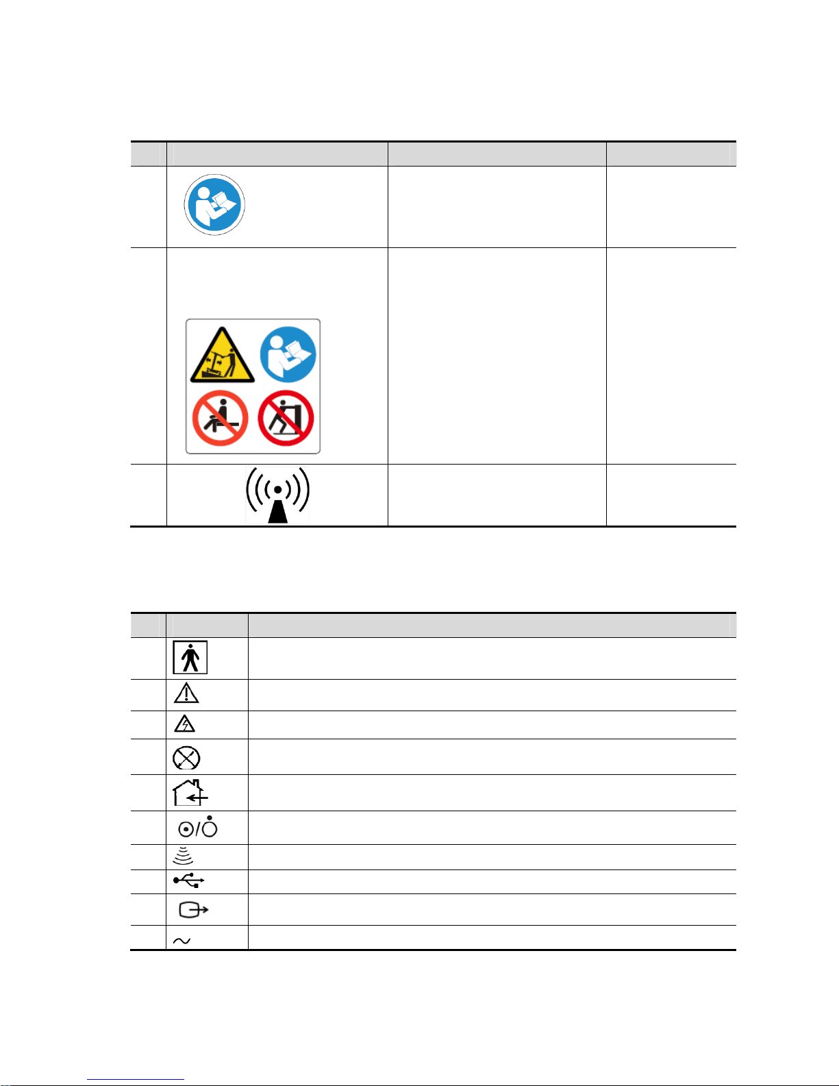
1.2.2 Warning Labels
No. Warning Labels Description Label Position
1.
Read the manual carefully before
using the system.
On the upper right
corner of the
control panel
2.
The following labels are available
when the system works with the
mobile trolley.
a. Do not place the system on a
sloped surface. Otherwise the
system may slide, resulting in
personal injury or the system
malfunction. Two persons are
required to move the system over
a sloped surface.
b. Do not sit on the system.
c. DO NOT push the system when
the casters are locked.
The top of trolley
panel
3
Non-ionizing radiation /
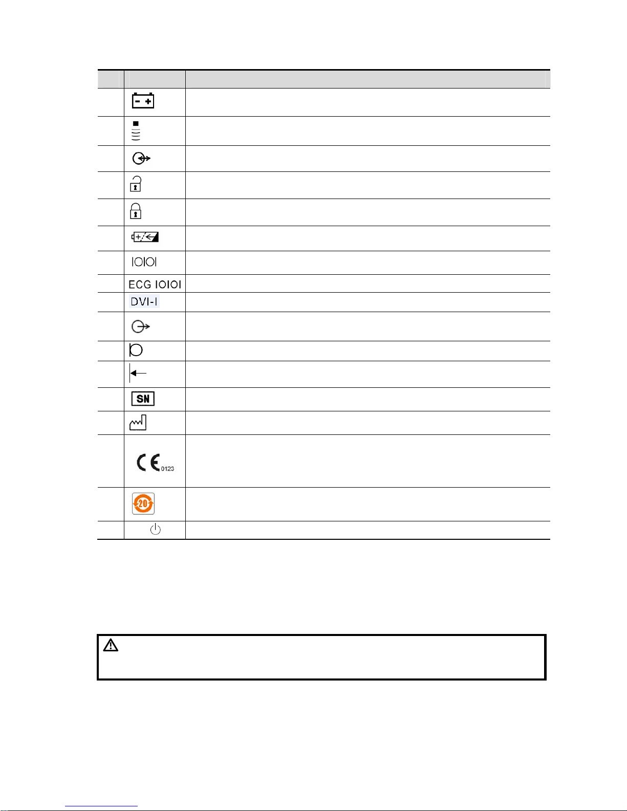
1.2.3 General Symbols
This symbols used in the device are listed in the following table. Meanings are:
No. Symbol Description
1
Type-BF applied part
2
To avoid safety accidents, refer to relevant content in the manual.
3
Dangerous voltage
4
No user serviceable parts (applied to the power adapter)
5
Indoor, dry location use only (applied to the power adapter)
6
Power button
7
Probe sockets
8
USB port
9
S-VIDEO signal port; VIDEO signal port
10
AC (Alternating current)
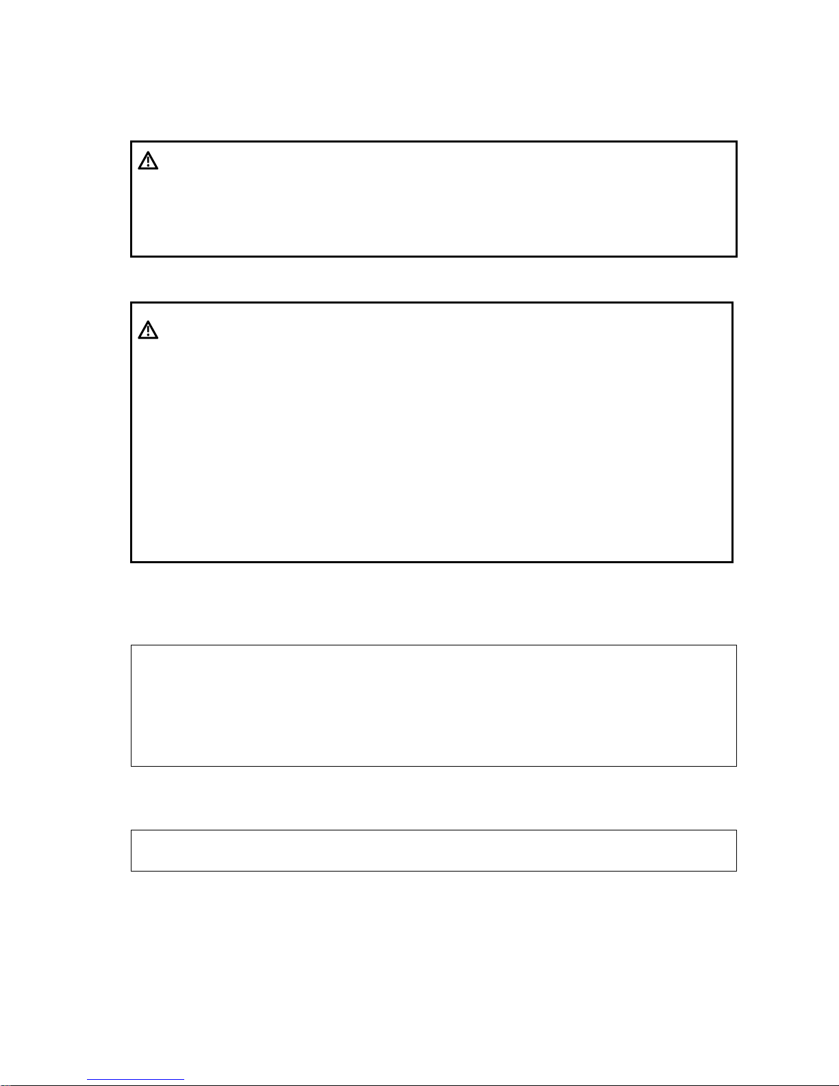
Page 16
Safety Precautions 1-3
No. Symbol Description
11
Battery Status Indicator
12
Pencil probe port (reserved)
13
IO extend port
14
unlocked symbol
15
locked symbol
16
Battery installation position indicator
17
Connects serial port devices
18
ECG function
19
Connects a display monitor or projector
20
Audio signal
21
Microphone input jack
22
Remote control port
23
Product serial number
24
Manufacture date
25
This product is provided with a CE marking in accordance with the regulations
stated in Council Directive 93 / 42 / EEC concerning Medical Devices. The number
adjacent to the CE marking (0123) is the number of the EU-notified body certified for
meeting the requirements of the Directive.
26
The environment-protective application period of the system is 20 years period.
27
Standby
1.3 Safety Precautions
Please read the following precautions carefully to ensure the safety of the patient and the
operator when using the probes.
DANGER:
Do not operate this system in an atmosphere containing flammable
or explosive gases such as anesthetic gases, oxygen, and hydrogen
or explosive fluid such as ethanol because an explosion may occur.
Page 17

1-4 Safety Precautions
1.3.1 Electric Safety
WARNING:
1.
Connect the power plug of this system and power plugs of the
peripherals to wall receptacles that meet the ratings indicated
on the rating nameplate. Using a multifunctional receptacle may
affect the system grounding performance, and cause the
leakage current to exceed safety requirements. Use the power
cord accompanied with the system provided by Mindray.
2.
Disconnect the AC power before you clean or uninstall the
ultrasound machine, otherwise, electric shock may result.
3.
When using peripherals not powered by the auxiliary output of the
ultrasound system, or using peripherals other than permitted by
Mindray , make sure t he overall leakage current of peripherals and
the ultrasound system meets the requiremen t of the local medical
device electrical regulation (like enclosure leakage current should
be no more than 500uA of IEC 60601-1-1), and the responsibility is
held by the user .
4.
In maintenance or assembly/disassembly, make sure other
cables are connected well before the battery connecting cable is
connected, otherwise the system may be damaged due to
hot-plug.
5.
Do not use this system simultaneously with equipment such as
an electrosurgical unit, high-frequency therapy equipment, or a
defibrillator, etc.; otherwise electric shock may result.
6.
This system is not water-proof. If any water is sprayed on or into
the system, electric shock may result.
CAUTION:
1.
DO NOT connect or disconnect the system’s power cord or its
accessories (e.g., a printer or a recorder) without turning OFF
the power first. This may damage the system and its
accessories or cause electric shock.
2.
Avoid electromagnetic radiation when perform performance test
on the ultrasound system.
3.
In an electrostatic sensitive environment, don’t touch the device
directly. Please wear electrostatic protecting gloves if
necessary.
4.
You should use the ECG leads provided with the ECG module.
Otherwise it may result in electric shock.
5. Maximum output power
of the trolley is 240 VA.
Page 18
Safety Precautions 1-5
1.3.2 Mechanical Safety
WARNING:
1.
When moving the system, you should first power off the
system, fold the LCD display, disconnect the system from other
devices (including probes) and disconnect the system from the
power supply.
2.
Do not subject the transducers to knocks or drops. Use of a
defective probe may cause electric shock to the patient.
CAUTION:
1.
Do not expose the system to excessive vibration (during the
transportation) to avoid device dropping, collision, or
mechanical damage.
2.
When you place the system on the mobile trolley and move them
together, you must secure all objects on the mobile trolley to
prevent them from falling. Otherwise you should separate the
system from the mobile trolley and move them individually.
When you have to move the system with the mobile trolley
upward or downward the stairs, you must separate them first
and then move them individually.
3.
Do not move the ultrasound system if the HDD indicator is
green, sudden shake may cause the HDD in damage.4 When
moving the trolley with mounted system, please take care of the
connector of the power adapter in case of damage.
1.3.3 Personnel Safety
Note:
1.
The user is not allowed to open the covers and panel of the system, neither
device disassemble is allowed.
2.
To ensure the system performance and safety, only Mindray engineers or
engineers authorized by Mindray can perform maintenance.
3.
Only technical professionals from Mindray or engineers authorized by Mindray
after training can perform maintenance.
1.3.4 Others
Note:
For detailed operation and other information about the ultrasound system, please refer
to the operator’s manual.
Page 19
Product Specifications 2-1
2 Product Specifications
2.1 Introduction
2.1.1 Intended Use
The diagnostic ultrasound system is intended for use in clinical ultrasonic diagnosis.
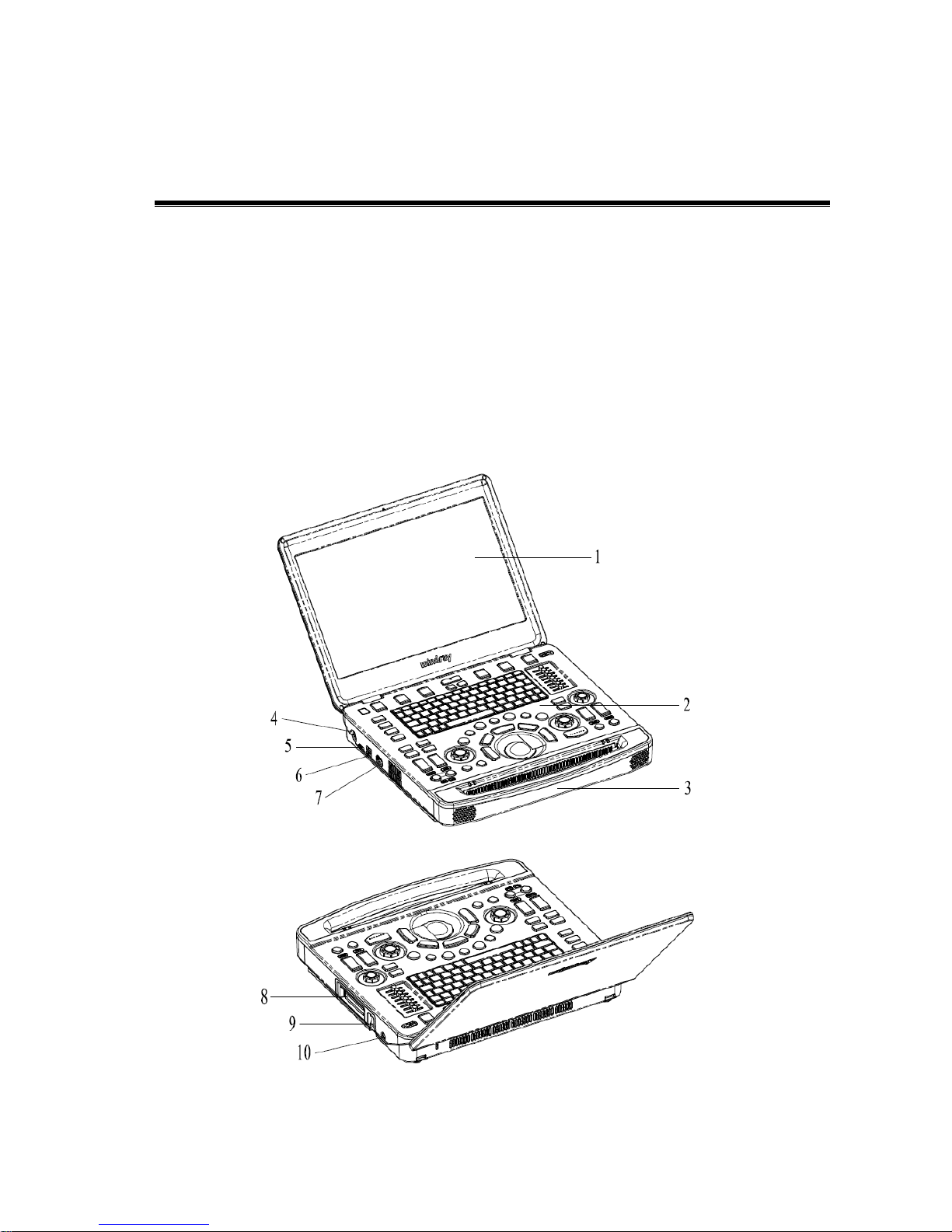
2.1.2 System Appearance
Page 20
2-2 Product Specifications
No. Name Function
1 Monitor Displays the images and parameters during the scan.
2 Control Panel Operator-system interface or control
3 Handle Used for carrying the system
4
Power input port
Connects the power adapter
5
HDMI port Outputs
high definition multimedia signals
6 USB port Connects USB devices (2 ports)
7 ECG port Connects ECG lead or DC-IN cable
8
Probe port
Connects a probe to the main unit; or connects a probe
extend module
9 Probe locking lever
Locks or unlocks the probe connected with the main unit
:locked symbol
:unlocked symbol
10 Pencil probe port Connects to a pencil probe.
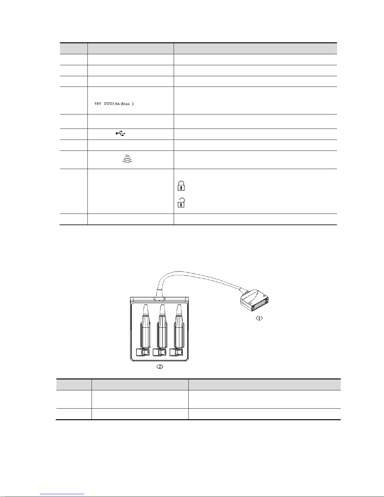
2.1.2.1 Extend Modules
Extend modules to the system are: probe extend module, video/audio extend module.
Probe extend module
No. Name Function
<1> Connector
Connects to the probe port of the main unit, and
extends the probe port to three.
<2> Probe port To extend ports for connecting probes
Page 21

Product Specifications 2-3
Note: 1. Perform the plug and unplug of the probe module. To reduce the wastage of probe
module, the operation should be conducted under frozen status of the system.
2. If you use the probe extend module to connect a probe, the image quality may be
degraded.
Audio/Video extend module
¾ Panel introduction
No. Symbol Function
<1>
Indicator
Used for connecting to main unit. The green
indicator is on.
<2>
Used for audio signal output.
<3>
Used for separate video output.
<4>
VGA
VGA signal output
¾ Connection
Connect the V/A extend module to the main unit via an HDMI port. As shown in the following figure.
Page 22

2-4 Product Specifications
2.1.2.2 Control Panel
Page 23

Product Specifications 2-5
No. Name English Name Description
1. B mode button B Press to enter B mode
2. P mode button P Press to enter Power mode.
3. C mode button C Press to enter the Color mode.
4. CW mode button CW Press to enter CW mode.
5. PW mode button PW Press to enter the PW mode.
6.
TDI Functional
buttons
TDI Press to enter TDI mode
7. M mode button M Press to enter the M mode.
8. Update button Update
Switching key: Press to change the
currently active window.
Start or end capturing the image in iScape
9. Measure button Measure
Press to enter/exit application
measurement
10. Caliper button Caliper Press to enter/exit general measurement
11. Trackball / To move the cursor.
12.
Confirm key
(left<Set> key)
/
Press to confirm key
13.
Confirm key (right
<Set> key)
/
14.
Angle adjustment and
quick angle knob
Angle Adjust the angle
15. Gain and iTouch knob iTouch
Adjust the gain of the image in various
modes
Press to enter iTouch mode
16. Cine button Cine
Press to enter/ exit the Cine Review
status.
Page 24

2-6 Product Specifications
No. Name English Name Description
17. Clear button Clear
Press to clear off the comments or
measurement calipers on the screen.
18. Freeze button Freeze Press to freeze or defreeze the image.
19. Power button / Power button
20.
Soft menu adjustment
button 1
/
Press to select the soft menu items
displayed on the bottom of the screen.
Refer to the subsequent contents for
specific functions.
21.
Soft menu adjustment
button 2
/
Press to select the soft menu items
displayed on the bottom of the screen.
Refer to the subsequent contents for
specific functions.
22.
Soft menu adjustment
button 3
/
Press to select the soft menu items
displayed on the bottom of the screen.
Refer to the subsequent contents for
specific functions.
23.
Soft menu page up
button
/
Press to turn the soft menu pages
upward.
24.
Soft menu page down
button
/ Press to turn soft menu pages downward.
25.
Soft menu display
mode switch button
/
Press to switch the mode for the soft
menu.
26.
Soft menu adjustment
button 4
/
Press to select the soft menu items
displayed on the bottom of the screen.
Refer to the subsequent contents for
specific functions.
27.
Soft menu adjustment
button 5
/
Press to select the soft menu items
displayed on the bottom of the screen.
Refer to the subsequent contents for
specific functions.
28.
Soft menu adjustment
button 6
/
Press to select the soft menu items
displayed on the bottom of the screen.
Refer to the subsequent contents for
specific functions.
29.
Patient information
button
Patient
Press to enter the Patient information
screen.
30.
Probe/exam mode
switch button
Probe/Exam Press to switch probe and exam mode
31. Image review button Review Press to review the stored images.
32. End exam button End Exam Press to end an exam.
33. User-defined key 3 P3 User-defined key
34. User-defined key 2 P2 User-defined key
Page 25

Product Specifications 2-7
No. Name English Name Description
35. Body mark button Body Mark Press to enter/ exit the body mark mode.
36. Cursor button Cursor Press to show/hide the cursor
37.
Baseline position
adjustment button
and auxiliary
interface
Baseline Adjust the baseline parameter.
38.
Scale adjustment
button and auxiliary
interface
Scale Adjust scale parameter.
39.
Steer/Invert
adjustment button
Steer/Invert Adjust steer/invert parameter.
40.
TGC and functional
interface
/ Move to adjust depth gain compensation.
41. Single-window button Single
Press to enter active window in Dual or
Quad mode.
42.
Dual-split window
button
Dual
Press to enter the Dual mode from
another mode;
Press to switch between the two windows
in the Dual mode.
43.
Image zoom and
spot/pan zoom switch
knob.
Zoom Press to enter or exit zoom status.
44.
Depth adjustment
button and fictional
interface
Depth Adjust depth
45.
Focus position
adjustment button
and functional
interface
Focus Position Adjust the focus position.
46.
Save static image
button
Save1
Press to save the image; user-defined
key.
47. User-defined key 1 P1 User-defined key
48.
Standby status
indicator
/
Standby indicator
Standby: blinking in orange
Other status: light off
49.
Hard disk read
indicator
/
Hard disk status indicator
The indicator blinks in green when hard
disk is running.
The indicator is off on the other status.
DO NOT move the machine when the
indicator blinking in green. Otherwise the
hard disk may be damaged by sudden
shake.
Page 26

2-8 Product Specifications
No. Name English Name Description
50. Battery indicator /
Battery status indicator.
Charging status:
It illuminates in orange when batteries are
charging;
It illuminates in green when batteries are
charged to full capacity;
Discharging status:
It illuminates in green when batteries are
charged fairly;
It illuminates in orange when batteries run
out.
51. AC power indicator /
AC indicator
The indicator is green at AC supply.
The indicator is off when batteries (AC
does not supply the power) supplied.
52. Esc Esc Cancel the operation or exit.
53. On-line help Help
Press to open or close the accompanying
help documents.
54.
Patient data
management system
iStation
Press to enter or exit patient information
system.
55. Report Report Open/ close the exam report.
56. User-defined key 5-8 P5~P8
User-defined keys, functions of which can
be defined in preset.
57. Stress echo Stress Echo Press to enter Stress Echo mode
58. Physiological signal Physio Press to enter or exit ECG.
59. Setup Setup Press to enter/ exit setup.
60. Biopsy Biopsy Press to enter biopsy
61. Set home Set Home Set home of comments
62. Quad-window display Quad
Enter Quad mode in Non-Quad mode;
Press to switch among interfaces in Quad
mode.
63.
iZoom (Full-screen
Zooming)
iZoom Enter/switch/exit full-screen zoom status.
64. Arrow Arrow Enter/exit the arrow comment status.
65. Home Home
Activate the Home function: return to start
position of comment.
66. Comments Comment Enter/exit the textual comment status.
Page 27

Product Specifications 2-9
No. Name English Name Description
67. Direction-control keys
/ Moves the cursor one letter each time; or,
select the ambient one in a selectable
area.
68. User-defined key 4 P4
User-defined keys, functions of which can
be defined in preset.
69. Alphanumeric keys / Enter characters.
For functions of undefined buttons or keys, the user can define it on your own. Refer to Operator
manual for details about function setting.
Functions of key combination
The system supports multi-language input; you can use the key combinations. The key
combinations include <Shift>, <Alt Gr>, <Ctrl> and some alphabet keys.
z <Shift> combination key
<Shift> + key: input the upper left letter of the key.
For the alphabet keys (<A>~<Z>), press <Shift>+key to input the letter of different case
with the current state.
z [Alt Gr] combination key
Combined with other letter keys, [Alt Gr] can be used for entering other languages.
Press [Alt Gr], and meanwhile press a letter key, the letter on the upper-right corner of the
key can be entered.
z [Ctrl] combination key
In iStation or Review screen, use <Ctrl> and <Set> to select more than one patient.
The combination of <Ctrl> and <Space> can switch the input between Chinese and
English.
z Combination key used together with [Fn] key
For those combination keys, press <Fn>+key to use the functions indicated with a frame on
the key.
No. Fn+ Name Function
1. → End Turn up the volume
2. ← Home Turn down the volume
3. ↑ Pg Up Increase the brightness of the LCD display.
4. ↓ Pg Dn Decrease the brightness of the LCD display.
Page 28

2-10 Product Specifications
2.1.3 Trolley Appearance
Page 29
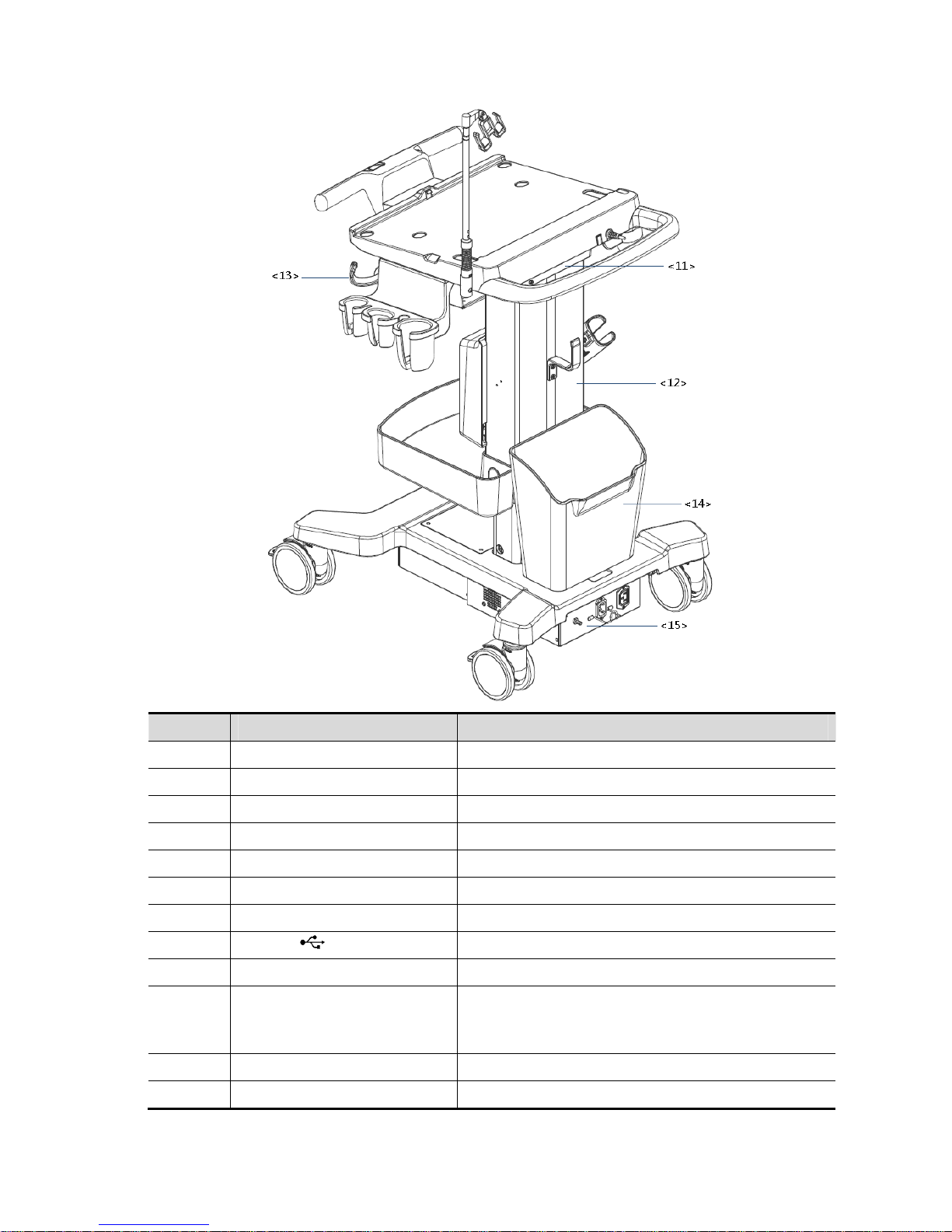
Product Specifications 2-11
No. Name Function
<1> Probe cable hook Manage probe cable
<2> Ultrasound main unit Ultrasound system
<3> Ascending/descending switch Press to adjust the height of operation panel
<4> Anti-theft setting Used to fix the ultrasound system to the trolley.
<5> Printer bracket Used to place the printer
<6> Probe extend module Used to extend ports for connecting probes (optional)
<7> Storage tray Used to place the adaptor, gel and other stuff.
<8> USB port Connects USB devices (2 ports)
<9> Probe holder Used to place probes temporarily
<10> Caster
Used for securing or moving the system
Step on the second footswitch to lock the trolley. Step
on the first footswitch to unlock the trolley.
<11> Audio/video extender Used to switch audio/video (optional)
<12> Lifting column Used to adjust the height of operation panel
Page 30
2-12 Product Specifications
No. Name Function
<13> Moveable hook Manage probe cable
<14> Storage box Used to place report or other stuff.
<15> Power supply panel
Used to offer output/input port, equipotential terminal
for power supply.
<16> Indicator
Battery indicator:
z It illuminates in orange when batteries are
charging;
z It illuminates in green when batteries are in
the charge.
z It illuminates in green when batteries are
charged fairly;
z It illuminates in orange when batteries run
out.
AC power indicator:
z The indicator is green at AC supply.
The indicator is off when batteries (AC does not supply
the power) supplied.
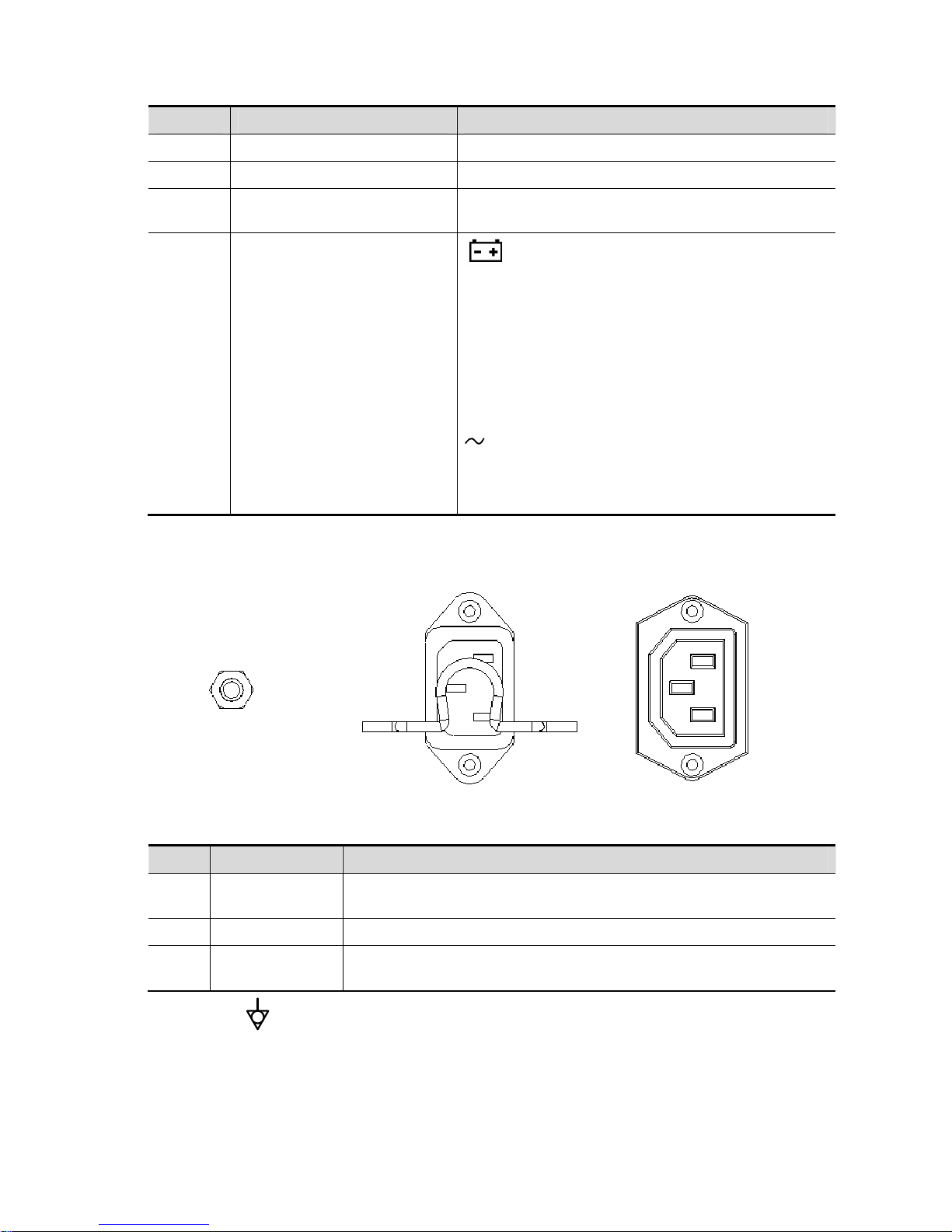
2.1.3.1 Power Supply Panel
<1>
<3>
<2>
No. Name Function
1
Equipotential
terminal
Used for equipotential connection, balancing the protective earth
potentials between the device and other electrical equipment.
2 Power inlet AC power inlet
3
Power supply
outlet
Supply power for optional peripheral devices (e.g. DVR)
The symbol represents the equipotential terminal that is used for balancing the protective
earth potentials between the system and other electrical equipment.
Page 31

Product Specifications 2-13
WARNING:
1.
Be sure to connect the equipotential wire before inserting the
power plug into the receptacle; be sure to pull out the power
plug from the receptacle before disconnecting the equipotential
wire; otherwise electric shock may result.
2. When you connect another device to this system, you should
use the equipotential wire to connect each of equipotential
terminals; otherwise electric shock may result.
3. Connect the earth cable before turning ON the system.
Disconnect the earth cable after turning OFF the system.
Otherwise electric shock may result.
4. DO NOT connect this system to outlets with the same circuit
breakers and fuses that control the current to devices such as
life-support systems. If this system malfunctions and generates
over current, or when there is an instant aneous current at power
ON, the circuit breakers and fuses of the building’s supply
circuit may be tripped.
2.1.4 Peripherals Supported
The peripheral devices supported by the system. The information is shown as below:
No. Item Model
1. Graph/text printer
HP Deskjet 1050 J410 series
HP Officejet 7000 wide format
HP Officejet Pro 8100
2. Black/white video printer
MITSUBISHI P95DW-N
SONY UP-D897
SONY UP-D898MD
SONY UP-X898MD
3. Digital color video printer
SONY UP-D25MD
4. Barcode reader
SYMBOL DS6707-SR
SYMBOL LS2208-SR
5. DVR
6. External DVD R/W drive ASUS DVD SDRW-08D2S-U
NOTE: printer UP-D898MD and UP-X898MD should be used in compatible with 1.00.7 2015-1-27
OS version or above versions. You can also select “DVR: 897” in the DIGITAL -> - DRIVER path on
the printer (use UPD897 driver) if OS is not updated.
WARNING:
This device complies with IEC60601-1-2:2007, and its RF emission
meets the requirements of CISPR11 Class B. In a domestic
environment, the customer or the user should guarantee to connect
the system with Class B peripheral devices; otherwise RF
interference may result and the customer or the user must take
adequate measures accordingly.
Page 32

2-14 Product Specifications
2.2 Specifications
2.2.1 External Dimensions and Weight
Size: (362±5) X (390±5) X (59±3) mm
Weight (built-in battery assembly): < 6.5KG
2.2.2 Electric Specifications
2.2.2.1 AC IN
Main unit
Trolley
Voltage of
power supply
100-240V~
Frequency of
power supply
50/60Hz
Output power 500VA
2.2.2.2 Battery
Main unit battery:
Trolley battery
Voltage 100-240V~ (for adapter)
Frequency 50/60Hz (for adapter)
Output
power
2.0 A max (for adaptor)
Voltage 14.8V
Battery
capacity
5800mAh (one battery) x 2
Voltage 14.8V
Battery
capacity
6600mAh (one battery) x 2
Page 33
Product Specifications 2-15
2.2.3 Environment Specifications
2.2.4 Monitor Specifications
Operational Conditions Storage and Transportation
Conditions
Ambient
temperature
0℃-40℃ -20℃-55℃
Relative
humidity
30%-85% (no condensation) 20%-95% (no condensation)
Atmospheric
pressure
700hPa-1060hPa 700hPa-1060hPa
WARNING:
Do not use this system in the conditions other than those
specified.
Working
voltage
12V
Monitor size 15.6 inches; 16: 9
Resolution 1920×1080
Visual angle ≥160
Page 34

Page 35

System Installation 3-1
3 System Installation
3.1 Installation Preparations
Note:
Do not install the machine in the following locations:
Locations near heat generators
Locations with high humidity
Locations with flammable gases
3.1.1 Electrical Requirements
3.1.1.1 Re quirements of Regulator
See Chapter 2.2.2 for power supply specifications. Due to the difference of the power supply
stability of different districts, please advise the user to adopt a regulator of good quality and
performance such as an on-line UPS.
3.1.1.2 Grounding Requirements
The power cord of the system is a three-wire cable. The grounding terminal should be connected
with a power grounding cable to ensure that protective grounding works normally. Make sure that
the protective grounding works normally.
WARNING:
DO NOT connect this system to outlets with the same circuit
breakers and fuses that control the current of devices such as
life-support systems. If this system malfunctions and generates an
over-current, or when there is an instantaneous current at power
ON, the circuit breakers and fuses of the building’s supply circuit
may be tripped.
3.1.1.3 EMI Limitation
Ultrasound machines are susceptible to Electromagnetic Interference (EMI) from radio frequencies,
magnetic fields, and transient in the air wiring. They also generate EMI. Possible EMI sources
should be identified before the unit is installed.
These sources include: medical lasers, scanners, monitors, cauterizing guns and so on. Besides,
other devices that may result in high frequency electromagnetic interference such as mobile phone,
radio transceiver and wireless remote control toys are not allowed to be presented or used in the
room. Turn off those devices to make sure the ultrasound system can work in a normal way.
Page 36

3-2 System Installation
3.1.2 Installation Condition
3.1.2.1 Space Requirements
Place the system with the necessary accessories at a proper position for convenient use.
Place the system in a room with good ventilation or having an air conditioning unit.
Maintain a generous – free air flowing space around the back and both sides of the system; failure
may result due to increased rise in system operating temperature.
A combination lighting system in the room (dim/bright) is recommended.
Except the receptacle dedicated for the ultrasound system, at least 3-4 spare receptacles on the
wall are available for the other medical devices and peripheral devices.
Power outlet and place for any external peripheral are within 2 m of each other with peripheral
within 1 m of the unit to connect cables.
3.1.2.2 Network Environment
Both wireless and wired LAN functions are supported by this ultrasound device.
Data transmission is allowed between different departments or areas without network cable.
Network can be automatically connected after disconnection in case that the device is required to
be moved, wireless transmission task can be recovered after the network resumed to normal
condition. Confirm the network devices and network conditions before the installation.
General information: default gateway IP address, and the other routers related information.
DICOM application information: DICOM server name, DICOM port, channels, and IP address.
3.1.3 Installation Confirmation
Please confirm the following items before installation:
z The video format of installation area or country.
z The language of installation area or country.
z Power frequency of installation area or country.
z The universal obstetrics formula and other measurement formula of installation area or country.
z The preset values of installation area or country that are different from the default values.
z The doctor’s operation habits.
z The items above prior to the installation training, and do the system settings according to the
universal setting of installed region or country.
3.2 Unpacking
Unpacking tool: scissor
Installation duration: 2 people, 10 minutes.
3.2.1 Unpacking Process
3.2.1.1 Trolley Unpacking
1. Use the scissor to cut off four white tapes around the external package as follows:
Page 37

System Installation 3-3
2. Take out the wooden cover.
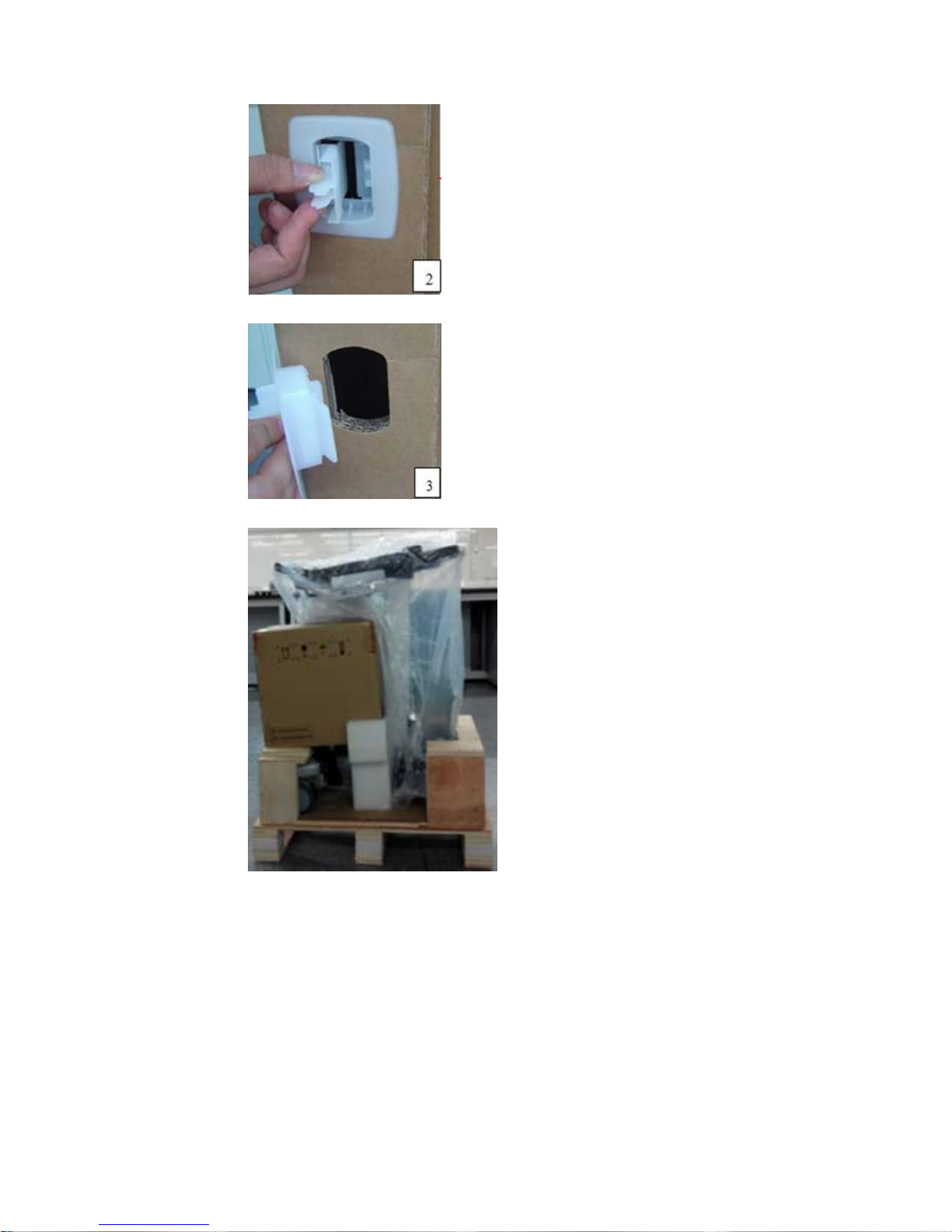
3. Unpacking
z Remove the box upwards if the space is commodious enough;
z If the space is not commodious enough, please follow the instructions below:
Press the middle of plastic clasp on the one side of the box as shown below;
Pull out the plastic clasp;
Page 38
3-4 System Installation
Take out the plastic clasp out of the box (5 plastic clasps);
Take off the plastic clasps to open the box.
4. Take out the foam of M9’s top plate.
5. Take out the auxiliary box.
Page 39

System Installation 3-5
6. Take out foam lifting of the trolley.
7. Take out the fixing board
8. Turn the wooden cover to a slope.
9. Push the trolley down over the wooden slope.
Page 40
3-6 System Installation
3.2.1.2 Unpack Main Unit
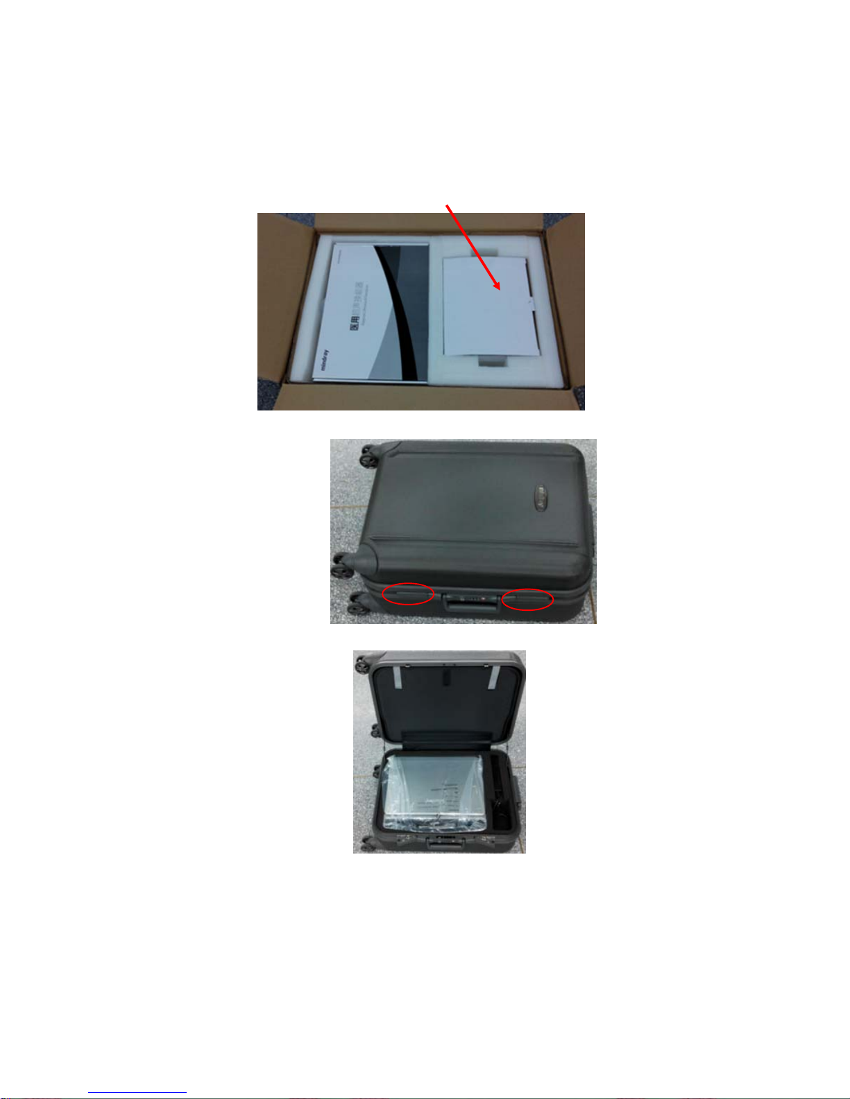
1. Cut off four tapes of the external package, open the external box, and take out the auxiliary box
and fixing foam;
2. Take out the trolley case.
3. Unlock the clasp to open the trolley case.
4. Take out the main unit and adaptor.
5. Take out other attachments
Page 41

System Installation 3-7
6. Take out the probe.
3.2.2 Check
1. After unpacking, check the objects in the container with the package list to see if anything is in
short supply or is wrong.
2. Inspect and make sure there is no damage to the machine, no indentation, no cracks. If there is,
please contact Mindray Customer Service Department.
3.3 Installation of Whole Device
3.3.1 Connecting Power Cable
Connect the connector of the power adapter to the adapter port in the system. Use a three-wire
cable to connect the adapter with the external power supply.
3.3.2 Connecting ECG
Connect the ECG cable to the corresponding lead interface on ECG of the ultrasound device.
3.3.3 Connecting a Ultrasound Probe
WARNING:
The probes, cables and connectors are in proper operating order
and free from surface defects, cracks and peeling. Using a
defective probe may cause electric shock.
Keep the cable end of the probe to the right side of the system, and insert the connector into the
port of the system, and then press in fully. See the figure below.
Page 42

3-8 System Installation
Toggle the locking lever to the top position.
Place the probe properly to avoid being treaded or wrapping with other devices. DO NOT allow the
probe head to hang free.
3.4 Installing Peripherals
Please see Chapter 2.1.4 for the device model that the system supports.
3.4.1 Connecting the Footswitch
The system supports footswitch of USB port type. As shown in the following figure.
You can set the functions of the footswitch in the [Key Config] page. Refer to Operator’s Manual for
footswitch setup.
3.4.2 Connecting/Removing a USB Memory Device
WARNING:
DO NOT directly remove a USB memory device; otherwise, the
USB device and/or the ultrasound system may be damaged.
When connecting a USB memory device to the ultrasound system via a USB port, You can hear
a sound if it is connected successfully. You can see the icon
in the lower right corner of
the imaging screen.
To remove the USB memory device: Click the icon
. Press <Set>, as shown in the figure
below. Select the memory device to be removed. Click [OK] to remove the USB memory device.
There will be sound feedback when removing the USB memory device.
3.4.3 Graph/Text Printer
Connecting a local printer
Note: Printers listed in Chapter 2.1.4 have drivers installed already.
Page 43
System Installation 3-9
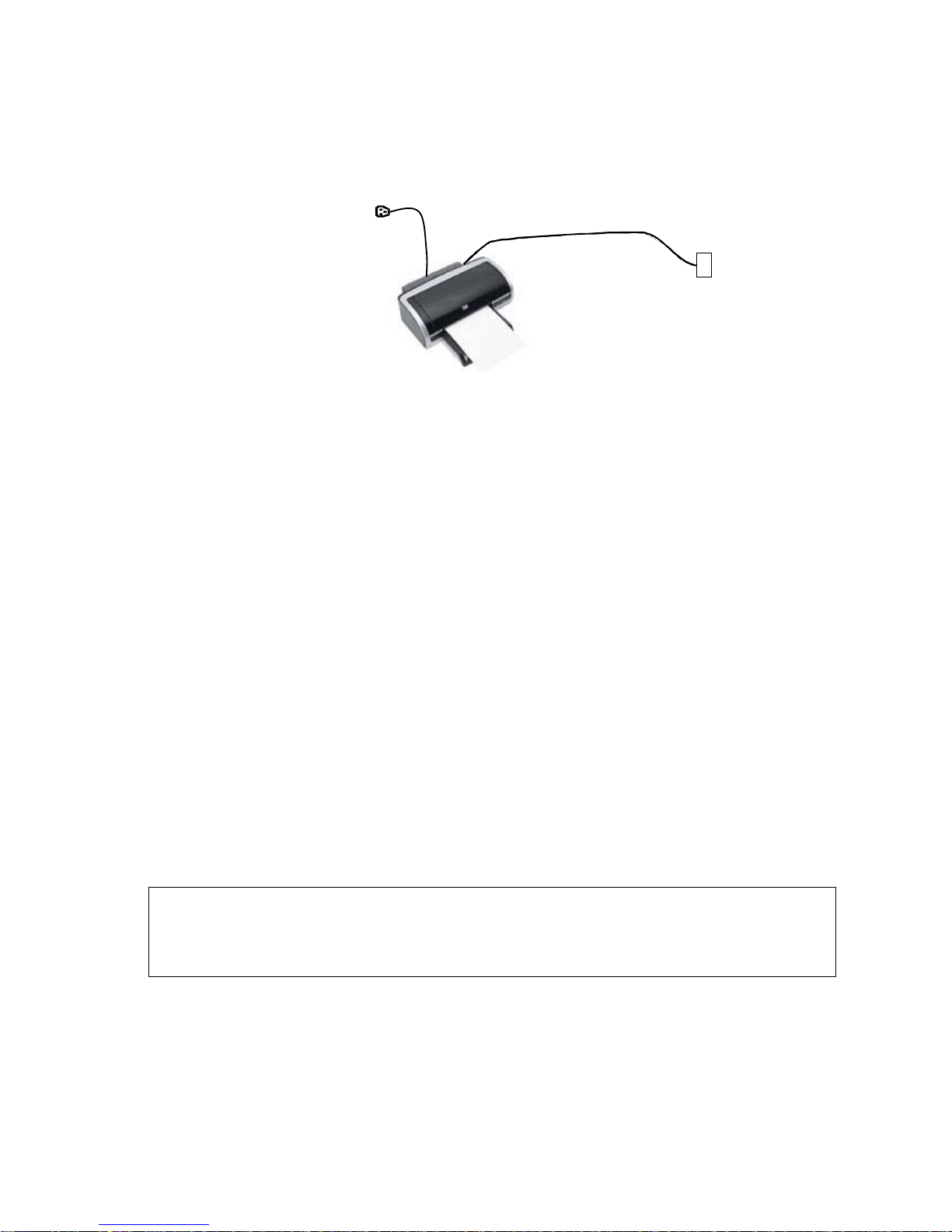
As shown in the figure below, a graph / text printer has a power cord and data cable. The power
cord shall be directly plugged into a well-grounded outlet.
1. Connect the data cable to the USB port on the ultrasound system.
2. Power the system and the printer on.
3. Put the installation optical disk of the printer driver into the external DVD R/W drive.
4. Install the printer driver: Select [Setup]→[Print Preset]→[Add Printer].
Note: all the operations are finished with left <Set> key.
5. Select [Add a local printer] and click [Next] to enter the screen of browsing driver.
Note: see the printer’s operation manual to select the port, or try to use the default port of the
system.
6. Click [Have Disk] to find the driver path (the installation type should be WIN7 64), and then click
[Next] to install the driver.
7. Complete the operation according to the tips on the screen. Click [Finish] to end the installation.
Add network printer
1. As the system is connected into a LAN, open [Setup]-> [Printer Preset] screen.
2. Click [Add Printer], select [Add a network, wireless or Bluetooth printer].
3. The system starts to search all available printers within the network. Select the target
printer and click [Next], the system tries to connect to this printer.
4. When the connection is successful, the system prompts the dialogue box, click [Next]
according to the screen tips and then click [Finish].The printer is installed successfully.
Tips: the system has combined many types/brands of printer drivers, if targeted printer drive is not
included in the system, you may need to install the driver for the network printer. Please use the
optical disk or
virus-free U disk with the driver to install according to the system prompts.
NOTE: 1. When you install the printer’s driver, you must specify the specific path for installation.
A vague path may result in longer searching times.
2. The network printer functions depending on the configured network environment in
the hospital, please consult the network configuration manager in case of failure.
Print
Both report and image can be printed on a graph / text printer.
z To set the default report printer and its attribute:
In "[Setup]→[Print Preset]" screen, select the "Report Print" column in the service list. You
can select printer from the driver list next to “Printer” in the lower screen and set the items
in the "Property" box. Click [Save] after you have finished setting.
Page 44

3-10 System Installation
z Report print
In Report screen, select [Print] to print the report.
If you want to use a shortcut key for report print, you need to define the user-defined key in
“Key Configuration”. For details, see Operator manual.
Please refer to the accompanying manuals of the printers for more details.
3.4.4 Video Printer
The system support video printers, consist of the B/W digital printers and color digital printers.
1. Position the printer in the proper place.
2. Plug the printer power cord into an appropriate outlet.
3. Use a USB cable to connect between the system's USB port and the printer's USB port.
4. Load a paper roll, and turn on the system and printer.
5. See section “3.4.3 Graph/Text Printer” for the driver installation procedure (printer drivers listed
in chapter “2.1.4 Peripherals Supported” are installed already).
6. Add a print service:
(1) Open the “[Setup] → [Print Preset]” screen.
(2) Click [Add Service] to enter the page.
(3) Select the service type and enter the service name manually.
Page 45

System Installation 3-11
(4) Click [OK] to return to the page.
(5) Select the target printer from the drop-down list in the “Property” box and set other printing
properties.
(6) Click [Save] to complete.
3.4.5 Barcode Reader
The system supports barcode reader to read the patient information (ID).
3.4.5.1 1-D Barcode Reader
1. The appearance of barcode reader. Each part of the barcode reader: LED indicator, scan
window and scan trigger button.
1. LED indicator Green light is on if scan is successful.
Red light is on if the scan fails.
2. Scan window Receive barcode.
3. Scan trigger button Press to perform the scan.
2. Plug connecting terminal of the cable to the port of the barcode reader. Ensure the contact
works well.
3. Connect USB terminal of the connecting cable to the USB port of main unit.
1. Barcode reader port
Page 46

3-12 System Installation
2. Connecting terminal of connecting cable
4. Press scan trigger button to receive barcode when ultrasound device is running (without
installing driving program). For more operation details, see relevant barcode reader manual.
3.4.5.2 2-D Barcode Reader
Install the connecting cable
1. The appearance of barcode reader. Each part of the barcode reader: LED indicator, scan
window and scan trigger button.
1. LED indicator Green light is on if scan is successful.
Red light is on if the scan fails.
2. Scan window Receive barcode.
3. Scan trigger button Press to perform the scan.
2. Plug connecting terminal of the cable to the port of the barcode reader. Ensure the contact
works well.
3. Connect USB terminal of the connecting cable to the USB port of main unit.
4. Press scan trigger button to receive barcode when ultrasound device is running (without
installing driving program). For more operation details, see relevant barcode reader manual.
Disconnect the connecting cable
Page 47

System Installation 3-13
1. Using the tip of a screwdriver or some other tools with a sharp head, depress the cable’s
modular connector clip.
2. Carefully slide out the cable.
Page 48

3-14 System Installation
3.5 Wired Network Connection
Connect the USB plug of the USB to LAN Adapter to the USB port on the machine, and insert the
network cable into the LAN port of the adapter to get a wired network connection.
WARNING
The LAN port of the adapter CAN ONLY be used to connect to wired network.
Device interconnection using the adapter through LAN port i s forbidden;
otherwise, electric shock may result. If you intend to connect an external d evice,
please make sure it meets the requirement of STANDARD GB9706.15 or
IEC60601-1:2005 chapter 16.
Note: the ultrasound system supports the following usb2lan devices for network connection:
Manufacturer Model
highspeed usb ethernet control /
Anker (USB3.0 to Gigabit Ethernet Adapter) A7611
J5create (USB3.0 to Gigabit Ethernet Adapter) JUE130
uGreen (USB3.0 to Gigabit Ethernet Adapter) 20258
In case of interfering the network communication, only one usb2lan device should be connected to
the system each time
3.6 System Configuration
3.6.1 Power-on Running
Connect the connecting terminal of the power adapter to the adapter port in the system. Use a
three-wire cable to connect the adapter with the external power supply. Ensure the connection of
ultrasound and optional device works well.
3.6.2 Enter Doppler
After the initialization process (about 1 minute), the system enters Doppler interface, as shown
below:
Page 49

System Installation 3-15
3.6.3 System Preset
1. Press [Setup]. Setup menu appears.
2. Click [System Preset] to enter System Preset interface.
Page 50

3-16 System Installation
The following settings can be performed on the System Preset interface.
Preset Interface Description
Region
To set the hospital name, language, time zone, system time format, system
date format and system date/time.
General
To set patient information, exam setup, patient management, image storage,
display, system dormancy, etc.
Image To set some general parameters in imaging modes.
Application
To set the measure caliper, measure setting, follicle method, comment setting,
etc.
OB
To set the relevant information about fetal gestational age, fetal growth curve
and fetal weight, etc.
Key Config To assign functions to footswitch and the user-defined keys.
Admin To set the user account control relevant information.
Scan Code To set relevant information of barcode.
3.6.4 Print Preset
Press <Setup> and click [Print Preset] to set video printer, graph/text printer parameters (set the
parameters according to the printer, and select the relevant printer services).
Page 51

System Installation 3-17
Print service setting
h Add Service: click to add print service.
h Remove Service: click to delete the selected print service.
h Rename Service: click to rename the selected print service.
h Default print service: click to set the selected print service as the default one.
h Set Service Property: to preset the service property, such as paper size, paper
orientation, etc. set the print service according to the type. The print service include:
report print, digital image print and analog image print.
See Chapter 2.1.4 for details in adding printer.
Image Settings
Click [Image Setting] to enter the page, you can set the brightness, contrast and saturation of
image printing, or you can use the default values.
3.6.5 Network Preset
3.6.5.1 iStorage Preset
Select [Preset]-[Network Preset]-[iStorage] to enter iStorage interface (see the figure below):
Page 52

3-18 System Installation
Name Description
Service Name The name of the iStorage service.
IP Address IP address of the iStorage service device.
Port Port for transmitting.
Connect Click to verify connection.
Add Click to add the Network service to the service list.
Update To save the changed parameters.
Delete Click to delete the selected service from the service list.
Add an iStorage service
1. Set the network server properties as described above.
2. Click [Add] to add the service to the Service list.
Modify a network service
1. Select the service to be updated in the service list.
2. You can see properties in the Configure Service area.
3. Modify the parameters and click [Update] to update the setting.
3.6.5.2 iConnection Preset
Set the parameters of mobile platform functions.
3.6.6 Network Configure
1. Press <Cursor> to show the cursor, click in the bottom bar to open the wireless network
manager.
Page 53
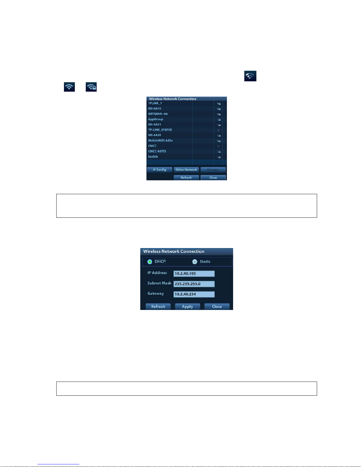
System Installation 3-19
2. Roll the trackball and press <Set> to select the target network, click [Connect] to connect to the
network.
When connecting an encrypted network, enter the password in the box first.You can select to
hide password characters or not.
3. The system tries to connect and the wireless manager icon turns into
. The icon turns into
or after successful connection.
IP Config
Note:
When the system background is processing network task (DICOM sending for example),
please do not enter network setting to change the IP, otherwise the background task may
fail. You can check if there are tasks undergoing in the task manager.
IP config is used for setting local network parameters, which is also applied to DICOM connection.
1. In Wireless network manager screen, click [IP Config] to open the page:
z
If “DHCP” is selected, the IP address will be automatically obtained from the DNS server.
h Click [Refresh] to check current IP address.
z If “Static” is selected (using a static IP address), enter the IP address.
h IP address of the system should be in the same network segment with the server.
h Subnet Mask: set different network segment.
h Gateway: set the gateway IP.
2. Click [Apply] to save current setting. Click [Close] to exit.
Note: If the IP address displays as 0.0.0.0, this means that the network is abnormal. The
reason for the failure may be disconnection or the system cannot obtain the IP address.
Page 54

3-20 System Installation
3.6.7 DICOM/HL7 Preset
Note:
Only if DICOM basic option is configured, [DICOM Preset] is available.
1. Click [DICOM Preset] to enter the DICOM Preset interface. Set DICOM service attributes first:
enter AE Title (use Application Entity title for ultrasound system), terminal and package size.
2. Server setting
1) Enter the device name and the IP address;
2) Verify connection after entering the correct IP address by clicking [Ping].
3) Click [Add] to add the server to the list if the connection works normally.
The following is an example:
Note:
1. AE Title should be the same with the SCU AE Title preset in the server
(PACS/RIS/HIS).
2. DICOM communication port should be the same with the one on the server.
3. If the currently entered name has already existed, the system will pop up:
“The server name exists!”
3. Click [DICOM Service].
Page 55

System Installation 3-21
When the system is configured with DICOM basic function module, and installed DICOM Worklist,
storage commitment, and Query/ Retrieve modules, the corresponding preset settings can be found
in DICOM Service screen.
The DICOM Service Setting is used to set properties of DICOM services. See the basic volume for
details.
Note:
Only if DICOM basic option is configured, Worklist page is available.
3.6.8 System Information Verification
Product configuration, version number, hardware board and relevant driver information appear on
the system information interface. Confirm the relevant information on this interface.
1. Click [About] to enter the interface.
2. All details about the hardware board appear on [About Detail] interface.
Note:
1.
Confirm the system information before and after the software maintenance.
2. If required, the system reminds the user of saving the current system
information.
Page 56

Page 57

Product Principle 4-1
4 Product Principle
4.1 General Structure of Main Unit’s
Hardware System
Figure
4-1 Schematic diagram of system hardwareThe general structure of M9’s hardware
system is shown in figure above. M9 system hardware consists of each following part:
¾ Main board
DC-DC circuit, which offers power supply, charges or discharges the battery.
Functional circuit of back-end offers the functions of stereo audio, video audio, IO
interface, etc.
Signal processing FPGA. It processes the beamforming signal and occupies the
functional controls except for transmitting and receiving functions.
Page 58

4-2 Product Principle
TRA FPGA is the FPGA which controls the transmission and the receiving.
65-128 transmitting/receiving channels.
Control interfaces related to probes.
4D&TEE functional circuit implements functions of 4D drive circuit and TEE
temperature measure, etc.
Power supply management (EC) implements functions of the power supply
management and control of starting/shutting down the main unit.
System monitoring (SM) implements the power supply monitoring and fan monitoring
of main system.
¾ TR64 board: 1-64 transmitting/receiving channels.
¾ Probe board connects the main unit with the probe.
¾ PHV power supply board produces the programmed high-voltage needed in the
transmission.
¾ COME module, also named as PC module, runs at Doppler platform.
¾ As a main display unit, LCD module displays the image and inducts the environment
brightness.
¾ ECG board offers ECG and respiratory signal acquisition and achieves the triggering
function with main unit.
4.2 Main Board
Main board includes: power supply, back-end and front-end.
Page 59

Product Principle 4-3
4.2.1 Power Supply
12VBUS
(12A)
Charger
Buck
Charger
2.5A Chg
4.6A Dsg
2.5A Chg
4.6A Dsg
19.0V/7.9A
AC/BAT
DCDC
DCDC
3V3STB(100mA)
5VSTB(500mA)
(240mA)
PWR_12V_EN_N
5VSTB_EN
DCDC
DCDC
DCDC
……
1V
1.2V
1.5V
5V
2V
3.3V
……
Figure 4-2 Principle diagram of power system
Function description:
¾ It provides the power to start the device and the power when the main unit is in standby.
¾ Battery charging or discharging circuit.
4.2.2 Backend
The backend is integrated with the circuit of the CPU module and main board.
FPGA
COME module
(PC module)
Gama
calibration
SSD
Wireless
net
adapter
USB
HDMI
LCD
Audio
circuit
Speaker
Circuit
control of
ultrasound
function
Control for
starting/shutting down
the device
Control
panel
Power
button
Power
supply
control
Button,
trackball
System
monitoring
SATA
PCIE
USB
HDMI
USB
HDA
LVDS
PCIE
LVDS
Figure
4-3 Principle diagram of power system
Page 60

4-4 Product Principle
Function description:
Circuit Unit Function
The control for
Starting and
shutting down the
device
Takes charge of starting and shutting down the device and
controls the indicator for starting and shutting down the
device
System monitoring Takes charge of battery management, fan control, voltage
detection, battery indicator control,
voltage detection and temperature detection
Wireless net
adapter
WIFI and Bluetooth
USB ports Provides two external USB 3.0 ports
SATA port SSD, mSATA type
HDMI Provides an HDMI port and supports 1920*1080 resolutions
(HD) output.
Audio Encodes and decodes the audio. Increases the power.
Signal process
FPGA
Connects CPU module with the ultrasound circuit
Control panel port Control panel port
LCD port Connects to LCD monitor screen, displays parameter board
screen and detects of environment brightness.
Other circuits
related to
ultrasound functions
¾ Transmitting/receiving control
¾ Probe control
¾ 4D, TEE probe control (reserved function, to be
released)
¾ PHV control
¾ ECG control
Page 61

Product Principle 4-5
4.2.3 Front-end of Main Board
Signal
process
FPGA
Mainboardtransmittingandreceiving
High-
voltage
pulse
output
circuit
Low-
voltage
drive
circuit
ATGC
High-
voltage
isolation
AFEclip
x8
Clock
TRA
FPGA
Clock
circuit
64ch
RX,
64ch
64ch
64ch
CW
receiving
circuit
Connectto
probevia
TR64
board
ControlTR
64board
Pencil
probe
receiving
switch
Pencil
probe
control
data
TRB
FPGA
65-128
channel
data
Transmitting
control
I/Qsignal
TX,64ch
PEN_RX
C
o
n
n
e
c
t
o
r
t
o
b
o
a
r
d
C
o
n
n
e
c
t
o
r
t
o
b
o
a
r
d
Fig 4-4 Systematical diagram of front-end of main board
The main functions of main board’s front-end unit:
¾ Control FPGA (TRA, implements the control of 65-128 channels transmitting and receiving,
ATGC adjustment and CW receiving control).
¾ Clock circuit
¾ Transmitting circuit (transmits the pulse with the achievement of 5 electric levels)
¾ High-voltage isolation
¾ AFE (receives echo signal)
¾ ATGC circuit (time gain compensation)
¾ CW receiving circuit (CW signal receiving)
Page 62

4-6 Product Principle
4.3 TR64 Board
Main board
TRA
FPGA
Signal
process
FPGA
TR64board
High-
voltage
pulse
output
circuit
Drive
circuit
High-
voltage
isolation
AFEclip
x8
Clockoffered
byCPU
TRB
FPGA
Clock
circuit
65-128
RX,
64ch
64ch
64ch
CPUATGC
Pencil
probe
transmitting
switch
Control
Data
Probe
board
Main
board
1-64
CW
transmitting
power
supply
Probe
control
SPI
TX,64ch
Transmitting
control
PEN_TX
C
T
B
C
T
B
C
T
B
Controlsignal
65-128
Fig
4-5 Principle diagram of TR64 board
The main functions of TR64 board:
¾ Control FPGA (TRB, implements the control of 1-64 channels transmitting and receiving,
ATGC adjustment and CW receiving control).
¾ Clock circuit provides the clock for transmitting/receiving chip.
¾ Transmitting circuit (transmits the pulse with the achievement of 5 electric levels and CW)
¾ High-voltage isolation
¾ AFE (receives echo signal)
¾ ATGC circuit (time gain compensation)
¾ Probe port function (Probe recognition signal, power supply control of the probe)
4.4 Probe Board
¾ Supports 192/128 array probe, phased array probe, bi-plane probe, and other nominal
probes, etc.
¾ Implements the connection between the main unit and the probe.
Page 63

Product Principle 4-7
¾ Implements the switch of 192 array probe within the probe. Probe board only supports
128
th
channel.
4.5 PHV Power Supply Board
Sampling
voltage
DAC_SDI
Figure 4-6 Diagram of PHV power supply board
Function description:
¾ PHV power supply board is the board that provides the power to the transmitting circuit.
AP100V, AN100V, PHV1P, PHV1N, PHV2P, PHV2N, CW_PWR_P and CW_PWR_N are
all outputs.
¾ PHV output goes into the power supply by producing the circuit via LDO.
¾ PHV input goes into the main board after being filtered.
4.6 ECG Unit
ECG module is designed for monitoring ECG signals and displaying ECG waveforms, which
serves as reference of ultrasound images. This module can synchronize with 2D images and
color flow images in real-time display. With R wave detected, ECG signals, after being
Page 64

4-8 Product Principle
magnified, filtered and sampled, are sent to DSC nodule via series port UART. Triggered ECG
signals that are detected are sent to control system for control. Then, it starts scan transmitting.
ECG transducer can be connected externally in this module design, which is also compatible
with other monitoring products manufactured by Mindray.ECG unit structure is shown as below:
Figure 4-7 Principle diagram of ECG board
Page 65
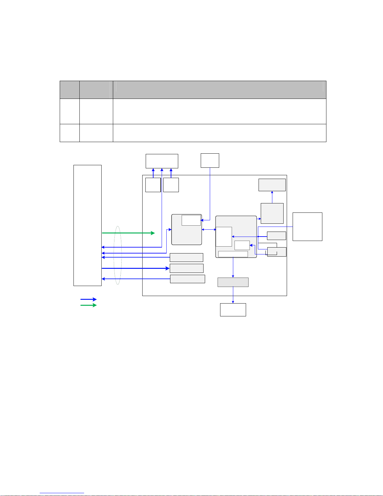
Product Principle 4-9
4.7 Control Panel
Control panel unit includes two boards, as shown below:
No. Board
Name
Description on Board Function
1 Control
Panel
LCD monitor folding/unfolding detection, power button, trackball, standard
keys on keyboard, user-defined functional keys, backlight control, status
indicator of the device, encoder, buzzer, TCG detection, etc.
2 TGC
Board
TCG adjustments in 8 segments
Control Panel
Main Board
System status
indicator
Power button
TGC Board
Function
button
Button
scan
LED
backlight
drive circuit
LED backlight
Buzzer
Buzzer drive
circuit
PWM generation
circuit
FPGA
12V、
5V、
5V_STB
MCU
SPI
Communication&control
Powersupply
QWERTY
keyboard
L
T
B
C
Encoder
Button
Encoder
info
process
Rotate
Trackball
module
USB
USB
Right
button
of
trackball
Left
button
of
trackball
ADC
circuit
Screen closed magnetic
detection switch
The functional diagram of the control panel unit is shown above. The main functions are described
in details.
1. FPGA module adopts FPGA and implements key scan detection, backlight control, encoder
detection, buzzer control and other functions.
2. MCU module implements USB communication, TGC detection, etc. FPGA and PSOC
communicate via SPI port: PSOC obtains detection result of FPGA via SPI port and sends the
result to the host by USB. PSOC obtains control information from the host via USB and sends it
to FPGA via SPI port. FPGA performs the control operations to corresponding units after
parsing control orders.
Page 66

4-10 Product Principle
3. TGC board implements the fix of TCG’s sliding rheostat.
4. Trackball sub-module communicates with the host via USB.
5. Sub-module of QWERTY keyboard adopts “thin film + silicon keys + structure keys” to
implement the standard keyboard.
6. Buzzer sub-unit adopts PWM waveforms that FPGA outputs to control the length and sound of
volume and frequency.
4.8 Main Display Unit
Test board
of
environment
brightness
Parameter
board
+12V+3.3V
LVDS
3.3V
I2C
Backlight
control
3.3V
I2C
Mainboardsocket
15.6"
1920*1080
LCDMonitor
LTBC
LTBC
LTBC
LTBC
Fig 4-8 Principle diagram of monitor
The monitor unit consists of LCD screen, connecting wires, parameter board, environmental light
detecting board, etc.
Function description:
¾ To make the display effect of LCD screen equal to that on the parameter board, parameter
board stores color temperature and gamma calibration data. It is necessary to update the
parameters in control panel for first time machine assembly or control panel/LCD screen
replacements.
¾ Signal processing FPGA calibrates the video signal that CPU board outputs based on the
information from parameter board, and then drives LCD display screen. Brightness and power
supply of LCD display screen are also controlled by this FPGA.
¾ Environmental light detecting board detects the brightness level of environment. To achieve
better display effect, main unit adjusts LCD brightness level according to the environment.
Page 67

Product Principle 4-11
4.9 Probe Extension Board
ProbeExtendBoard
Cprobesocket
260pin
Bprobesocket
260pin
Aprobesocket
260pin
POUTsignalswitch
(relayset)
CPLD
Probesignal
4D&TEEsignal
Probecontrol
circuit
Probecontrolsignal
12V/5.7V
/+100V/-100V
128channel
Transmitting/receivingsignal
260PIN
probe
connector
ProbeBoard
Communication
&control
Powersupply
Ultrasoundsignal
4D&TEEsignal
switch
(relayset)
Figure 4-9 Hardware diagram of probe extension board
Function description:
¾ Supports 192/128 array probe, 4D probe, phased array probe, bi-plane probe, and other
nominal probes, etc.
¾ Implements the switch of 192 array probe within the probe. Probe board only supports 128
channels.
¾ Probe board contains three 260pin Mini probe sockets.
¾ Supports the retrieving of three probes’ IDs and the switch among three probe socket. ID
recognition and the circuit of probe switch are independent to each other.
Page 68

4-12 Product Principle
4.10 Audio/Video Transfer Module
Figure 4-10 Function of audio/video extend module
Audio/video transfer board (or module) adopts non-standard HDMI input port. Main unit outputs
1920×1080p@60Hz HDMI 1.4a signal as input signal of the extender. The module supports line-out
video signal of analog stereo audio, xxxx×xxxx@60Hz analog RGB video signal, NTSC, S-Video
signal with format of PAL.
M9 audio/video transfer module includes: power supply, HDMI signal receiving, digital video signal
processing, and audio/video code.
Figure 4-11 Diagram of audio/video extend module
Page 69

Product Principle 4-13
4.11 USB HUB Board
USB main
port
USB sub-port USB sub-port
USB sub-port
USB sub-port
Repeater/Controller
Fig 4-12 Principle diagram of USB HUB board
The main functions of USB HUB board:
¾ Compatible with the USB 2.0 standard;
¾ One USB port can be subdivided for four USB ports (there are two ports in current products.)
¾ Detect the plug and unplug of USB device via main port.
¾ Charge the device connecting to USB via main port.
4.12 Trolley Power Supply
Trolley power supply provides the power to main unit system. AC-DC power supply provides the
power to main unit system when there is AC input. If there is no AC input, trolley power supply
provides the power to main unit system. Trolley power supply includes connecting board of trolley
power supply, AC-DC power supply, management board of trolley battery and two pieces of
chargeable lithium-ion batteries. The connection of each part is shown below:
Page 70

4-14 Product Principle
Figure 4-13 Diagram of related boards of trolley power supply
4.12.1 Connection Board of Trolley Power Supply
Main functions of connection board of trolley power supply:
¾ AC input transfer
¾ Auxiliary output control. Auxiliary output is enabled after starting main unit. Auxiliary output
disconnects when main unit is in standby or shuts down.
4.12.2 AC_DC Power Supply
AC_DC power supply implements power supply isolation and voltage transfer. It outputs 19 V DC
transferred from AC input. In terms of 150 W of main unit power and 50 W charging power, the
maximum power of AC_DC power supply is 200 W.
4.12.3 Management Board of Trolley Battery
The main functions of management board of trolley battery:
¾ Implements AC power supply and auto switch of battery supply. AC power supply has the
priority over others.
¾ Battery charge and battery management;
¾ AC status and battery status indication;
¾ Works with main unit system and recognizes the status of main unit system. Implements
auxiliary output control and low battery-consumption when the trolley is in standby.
Page 71

Product Principle 4-15
Principle diagram of management board of trolley battery is shown below:
Figure 4-14 Diagram of management board of trolley battery
4.13 System Power-on Control
Figure 4-15 System power-on diagram
Description of related controlling signals:
No. Controlling signal Description Comme
nts
1 PWR_BTN_N,
PWR_BTN#
Pulse signal that power-on button of control panel
produces passes to CPU board through FPGA,
and is used for starting the device.
2 S3# Output by CPU board, effectively represents that
CPU system is in standby (the electrical level of
S4# is high) and keeps 5VSTB powered on when
it is in standby via FPGA.
3 S4# Output by CPU board, effectively represents that
CPU system is in dormancy.
Page 72
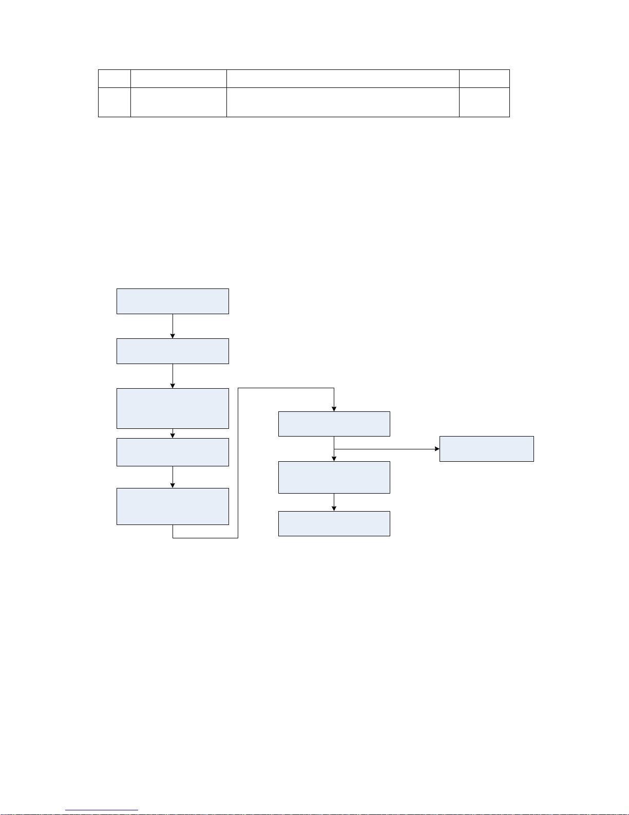
4-16 Product Principle
4 S5# The signal is not used currently
5 PWR_OK# Sent out by power management FPGA to CPU
board, indicates that the 12V is powered on.
¾ Power supply of main unit/battery enables the start of device.
¾ Power supply produces 5VSTB and 3.3VSTB as the AC inputs.
¾ Unplug AC when shutting down the device. Power supply cuts off 5VSTB output, but only
keeps the output of 3.3VSTB. Only with power button pressed again, it’s re-powered on.
¾ Unplug AC when the device is in standby. Batteries, for standby usage, provide the output of
5VSBT and 3.3VSTB.
¾ The process of power-on is shown below:
ConnecttoAC
Presspowerbutton
(controlpanel)
Receivevalid
PWR_BTN_N
(powersupplymgmt
FPGA)
Powersupplymgmt
sendsvalidPWRBTN#
signal
S3#andS4#invalid
(COMEmodule
sends)
DC-DC12Vpower-on
PWR_OKvalid
(powersupplymgmt
sends)
CPUstart
(COMEmodule)
DC-DCboardsends
powersupplyofother
circuits
Figure 4-16 Diagram of system power-on
Page 73
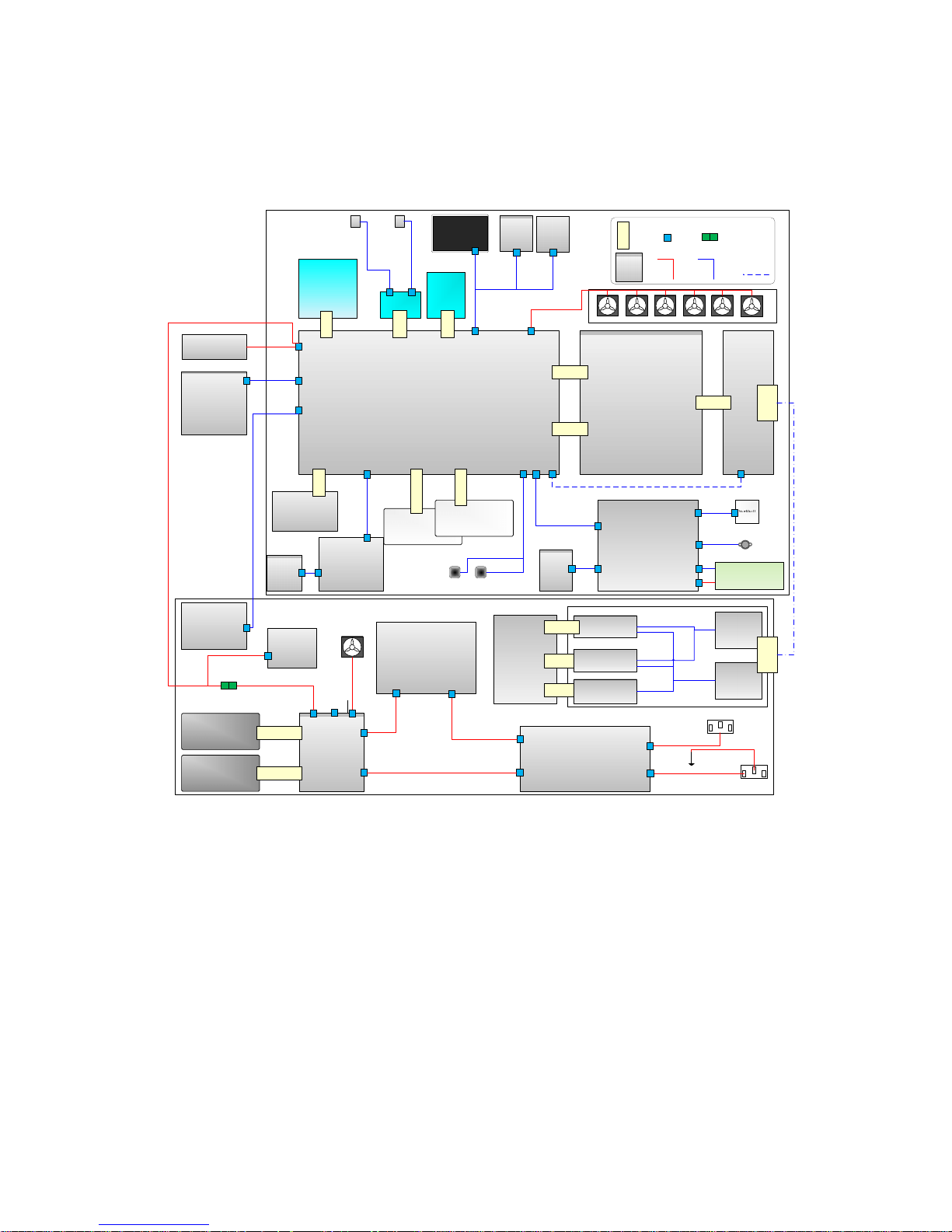
Product Principle 4-17
4.14 Internal Connection Diagram of Main Unit
and Tr olley
Probe connecting
board 1PCBA
Main board
LCD
Monitor
COME module
SSD
mSATA port
WiFi module
Battery
Battery
TR64 board
Probe board
ECG board
ECG
connecting
board
2*2*
110
mSA
TA
Mini
PCIE
2*78
2*60
6*40
Light
sensor
board
LCD
parameter
board
Wire
Power supply adapter
Audio/video transfer
module
USB HUB board
1*8
1*8
J6
J8
J17
J20
J22
J10
J24
J18
J1
J9
J12
J23
J5J4
J21
J1
J18
J2 J1
J3
J3
Control panel
TGC board
2116 small keyboard
Board to
board
socket
Board to
wire
socket
Board
Power
supply wire
material
Signal wire
material
Wire to
wire
socket
Reservation
design
Buzzer
Speaker
assembly
J15
J1
J1 J1
J11
J2
J5
J6
J4
J3
J1
J2
J5
J6
Connecting board of trolley power supply
Trolley battery
management board
AC-DC module
Battery
Battery
Trolley LED
board
AC output
AC input
1*11
1*11
J2
J3
J10
J4
J5
J6
J7
J1
J1
J2
J4
J3
Probe extend module
2*40
2*40
2*20
Probe connecting
board 2PCBA
M7 probe extender
4DConnecting board
PCBA
Aprobe
connecting
board PCB
M9 probe
extender
B connecting
probe
260
PIN
260
PIN
Probe extension
wire
Mainunit
Trolley
PHV power supply
board
2*20
J7
J1
Fan assembly
Fig
Figure
4-17 Internal connection diagram of main unit and trolley
4.15 Details in Main Unit’s Power-on
Start-up procedure of main unit and the performance of power supply & display in various steps are
shown below:
Page 74

4-18 Product Principle
Press Power
Button
EC ARM receives
signal
Effective
power-on
Exit, without
starting
N
Y
Enabling
CPU_PWR_BTN
COME module
receives signal
COME module
sends S3, and
starts power-on
flow
EC ARM receives
S3 signal
EC ARM enables
power supply of
main unit
Power supply
power-on
1V
……
EC ARM delay
DSP FPGA(PCIE
device)start
configuration
DSP FPGA(PCIE
device) complete
configuration
EC ARM sends
PWR_12V_OK
order
COME module
receives
PWR_12V_OK
COME module,
start BIOS
DSP FPGA(PCIE
device) in non-
reset status
Control panel
power-on
5V 12V
Control panel
FPGA
configuration
Control panel
PSOC BOOT
Initialize control
panel
(white backlight
is on)
Control panel
ready
No sign on
monitor
Initialize display.
Turn off
backlight. Do not
output LVDS
signal
No sign on
screen
DSP FPGA sends
LVDS data to
LCD
Open DSP FPGA
Open LCD
backlight, adjust
brightness
Backlight of
monitor
brightens. No
display
Correct image
displays on
monitor(BIOS
boot screen)
COME module,
output boot
screen
Work status (below
Power
Button),green,blinks
Work status
indicator (below
Power Button),
green, lighting
COME module,
complete BIOS
Complete OS
loading
Start loading OS
Display changes
of resolution
LOGO
(MINDRAY)
displays on
monitor
Adjust final
resolution
Enter OS
desktop
Image from
desktop displays
on monitor
No sign on
monitor
No sign on
monitor
Start Doppler
Doppler start
screen displays
on monitor
Hard disk
indicator,
green, blinks
AC is active
Active AC
indicator,green,
lighting
Battery supply
battery status
indicator,
green,lighting
Page 75

Checking Performance and Functions 5-1
5 Checking Performance and
Functions
5.1 Description
The chapter describes checking methods to main functions and performance. The methods are
only for reference.
5.2 Checking System Status
5.2.1 Running Status
1. Power on/off normal (duration time is normal), no abnormal sounds or occasion occur
during normal operation.
2. After ultrasound system gets started, the fan starts working, and no abnormal noise is
heard when the fan is working.
3. Check whether product configurations and software versions are normal via [About]
interface.
4. Check whether contrast and brightness of the monitor are normal.
5. Check whether time and date are valid and correct.
6. Check whether all status indicators are normal.
7. Check all log records together with the users to confirm whether there are any
abnormalities.
5.2.2 Working Condition
Check the ambient temperature and humidity. The measurement related to security features is
sensitive to humidity. If the insulation feature of the system deteriorates due to the increase of
system service time or system malfunctions, the fluctuation range of measurement results are likely
to increase with the humidity increasing.
Page 76

5-2 Checking Performance and Functions
5.3 General Check
5.3.1 Check Flow
Check the control panel
Check the monitor
Check peripherals
Check I/O port
Check ECG
5.3.2 Check Content
5.3.2.1 Check Control Panel
Procedure Checking criteria
1. Check all buttons, keys and knobs
Follow the direction: left to right, and up to down.
All keys and knobs are effective.
2. Trackball function check
z Press <Freeze> to enter frozen status and
move the trackball.
z Press <Measure> to enter measurement
status. Measure the vertical distance and
horizontal distance and perform other
trackball operations.
The move of the trackball is smooth. The
response to the cursor is rapid. The direction
the trackball goes is same with that of the
cursor.
Page 77

Checking Performance and Functions 5-3
5.3.2.2 Check Monitor
Procedure Checking criteria
z Monitor brightness adjustment
z Monitor contrast adjustment
z Monitor maintenance
Log on with the account named as
“Service”, select
[Preset]-[Maintenance]-[Test Main
Monitor] to check the monitor
functions.
z Height adjustment:
Auto adjustment: select [Preset]-[System
Preset]-[General]. Click [Brightness Auto
Adjustment] from [About].
Manual adjustment: press <Fn>+<
> to increase
the brightness. Press <Fn>+<
> to decrease the
brightness.
z Select [Preset]-[System Preset]-[General]. Click
[+] from [Contrast] to increase the contrast. Click
[-] to decrease the contrast.
z The monitor display works well after testing each
function. Bad points are:
1 Light dot is 0; blinking dot defect is 0.
2 The adjoining dark dots are no more than 3
pairs, and there are no adjoining dark dots in
image area.
3. 3 or 3 successive dark dots are no more than 0
pair.
The dark dots are no more than 7 and those in the
image area are no more than 2
5 The distance between bad dots is no less than
5mm.
Note: the image area refers to the area enclosed
by the rectangle with black/white background.
Page 78

5-4 Checking Performance and Functions
5.3.2.3 Checking Peripherals
Procedure Checking criteria
Footswitch: confirm the normal connection
between footswitch and USB port. Check
the configuration status of footswitch under
[Key Config] and corresponding
implementation. (E.g. right key-image
freeze; middle key-color print; left
key-white/black print).
Trigger the freeze key of the footswitch (right key).
Image freeze menu and freeze menu appear. The
image is unfrozen if the key is triggered again.
Trigger the print key of the footswitch (middle key).
Start color print.
Trigger the print key of the footswitch (left key). Start
black/white print.
Video printer: confirm the connection
between video printer and ultrasound
device works well and check the
implementation of each function.
Press the Print key which is setup well already to start
the print. The image has no defect or degradation.
Switch video output terminal. Then repeat the
previous steps.
Graph/text printer: confirm the connection
between graph/text printer and ultrasound
device works well and check the
implementation of each function.
Press the Print key which is setup well already to start
the print. The image has no defect or degradation.
Barcode reader: scan any piece of barcode
when the system is under running.
The barcode information displays on the image
interface. The information is correct compared with
the data information of barcode.
5.3.2.4 Checking ECG Module
Procedure Checking criteria
Perform the following tests after the
system is configured with ECG
module:
Connects ECG lead.
Move the cursor to image menu.
Click [Physio] to enter its interface.
ECG activation, ECG waveform and heart icon appear on
the right corner of the interface.
The parameters for [Scan speed], [ECG gain] and [ECG
position] can be adjusted in real-time.
Review ECG signals.
5.3.2.5 Checking I/O Interface
Procedure Checking criteria
Checking I/O interface
Verify video/audio interface, USB port, etc.
z VGA interface
Connect external VGA/LCD monitor (the resolution
should be one of them: 1920*1080,1024*768,
1280*1024,1280*720).
z Other USB ports
z The information on VGA/LCD monitor is
same with that on the screen of main
unit. The characters and images are
complete; the images are stable; no
color cast; no shaking and no blinking.
z Network connection and communication
work well.
z USB storage and read work well.
Page 79

Checking Performance and Functions 5-5
5.4 Functions Checking
Note: The chapter lists the system checking items with complete configurations and
describes them in details. If the items are not configured, the relevant tests can
be ignored.
5.4.1 Checking Flow
5.4.2 Checking Content
5.4.2.1 Imaging Mode
B-mode
In B mode scan, the image parameter area in the upper left corner of the screen displays the
real-time parameter values as follows:
Items F D G FR DR iClear iBeam iTouch
Meaning Frequency Depth Gain Frame
Rate
B
Dynamic
Range
Display when the function is
activated.
Parameters that can be adjusted to optimize the B Mode image are indicated in the following.
Adjustment Parameter Item
Control panel and
image soft menu
adjustment
Frequency (image quality), gain, depth, TGC, acoustic power, focus, scan
range, steer, ExFov, line density, dynamic range, iClear, persistence,
rotation/invert, iBeam, auto piecing, gray map, tint map, TSI, iTouch,
HScale, dual live, LGC, Echo, Boost.
Page 80

5-6 Checking Performance and Functions
Parameter Adjustment
Procedure Checking criteria
Press <B> button. Enter B mode image. B mode interface appears.
Frequency adjustment
B image soft menu-[Image
quality]
The real-time value of frequency is displayed in the image
parameter area in the upper right corner of the screen
(fundamental wave-F,
Harmonic frequency-H). Values of frequency
vary depending upon the probe types.
Gain adjustment G
Rotate <Gain> button
Gain increases with rotating the knob clockwise;
Gain decreases with rotating the knob anticlockwise;
Depth adjustment D
Press <Depth> button.
The depth of the image changes accordingly. Depth range varies
depending upon the probe types.
TGC adjustment
Adjust 8 sliders on the control
panel
Push the slider right to increase the gain. The brightness of the
area becomes brighter.
Push the slider right to decrease the gain. The brightness of the
area becomes darker.
About 1.5s after the adjustment is finished, the TGC curve
disappears.
Acoustic power adjustment
B image soft menu-[Acoustic
power].
The system offers 34 values to adjust the acoustic power.
Acoustic power (AP) is displayed in real time in the upper part of
the screen.
Focus
B image soft menu-[Focus
number]
Press <Focus Position> to
adjust focus position.
Focus position/number adjustment
The focus position icon
is displayed on the right side of the
image.
Scan range and FOV position
B image soft menu-[Scan
range].
Image display adjustment
[Scan range] is on and move the trackball to adjust the scan
range.
Steer
Press <Steer> arrow button.
To steer the beam the probe transmits.
ExFov
B image soft menu-[ExFov]
Click [ExFov] on the soft menu to enable/disable the function.
Line Density
B image soft menu-[Line
Density].
The function determines the quality and information of the image.
Levels of line density: UH/ H/ M/ L.
Dynamic Range
B image soft menu-[Dynamic
Range].
Rotate the knob clockwise to increase dynamic range; rotate the
knob counterclockwise to decrease dynamic range.
The adjusting range of parameter is 30-180 dB in increments of 5
dB.
iClear
B image soft menu-[iClear].
The system provides 7 levels of iClear effects adjustment, Off
represents iClear is disabled, and the bigger the value is the
stronger the effect becomes.
Page 81

Checking Performance and Functions 5-7
Persistence
B image soft
menu-[Persistence].
The system provides 7 level of persistence. The bigger the value
is the stronger the effect becomes.
Rotation/Invert
B image soft menu-[L/R
Flip]/[U/D Flip].
To invert the image horizontally or vertically.
Image can be rotated by the angle of 0°, 90°, 180° and 270°.
When the image is rotated in the angle of 90° or 270°, the depth
scale is displayed on the upper part of the screen.
The “M” mark indicates the direction of the image; the M mark is
located on the top of the imaging area by default.
iBeam
B image soft menu-[iBeam].
The system provides 4 values of iBeam in B mode. iBeam is
disabled when it is off.
Auto Merge
B image soft menu-[Auto
Merge].
In the Dual-split mode, when the images of the two windows have
the same probe type, depth, invert status, rotation status and
magnification factor, the system will merge the two images so as
to extend the field of vision.
Turn on or off the function through the [Auto Merge] item in the
soft menu;
Gray Map
B image soft menu-[Gray Map]
Adjust the gray from [Gray Map] on the soft menu;
There are 8 different maps available.
Tint Map
B image soft menu-[Tint Map]
Select the tint map from [Tint Map] on the soft menu.
Turn on or off the tint map from [Tint Map] on the soft menu.
TSI
B image soft menu-[TSI].
Select TSI from [TSI] on the soft menu.
The system provided 4 ways of optimization for specific tissues:
general, muscle, fluid and fat.
iTouch
Press <iTouch> button
Press <iTouch> on the control panel to enter the iTouch status, the
symbol of which will be displayed in the image parameter area of
the screen.
Click [iTouch] on the image menu to adjust the gain in iTouch
status among -12 through 12dB.
Long press <iTouch> to exit iTouch mode.
HScale
B image soft menu-[HScale]
Click [HScale] on the menu to display or hide the scale (HScale).
Dual live
B image soft menu-[Dual live].
Enable [Dual Live] on soft menu, and dual-split window of images
are displayed on the screen.
Two pages of adjustable parameters are displayed on the touch
screen as well; where, shared parameters and left window
parameters are displayed on the B(L) page, while right window
parameters are displayed on the B(R) page.
Switch the display mode via <Switch Mode> and adjust the image
parameters.
Page 82

5-8 Checking Performance and Functions
M mode
In M mode scan, the image parameter area on the right side of the screen displays the
real-time parameter values as follows:
Parameter Item F D G V DR
Meaning Frequency Depth M Gain M Speed M Dynamic Range
Parameters that can be adjusted to optimize the M Mode image are indicated in the following.
Adjustment Parameter Item
Control panel and
soft menu
adjustment
Gain, TGC, Depth, Focus Position, Display Format, Line Correlation, Tint
Map, Scan Speed, Edge Enhance, Dynamic Range, Gray Map.
Color mode
In Color mode scan, the image parameter area on the right side of the screen displays the
real-time parameter values as follows:
Parameter
Item
F G WF PRF
Meaning
Frequency Color
Gain
Color Wall
Filter
Pulse
Repetition
Frequency
Parameters that can be adjusted to optimize the Color mode image are indicated in the
following.
Adjustment Parameter Item
Control panel and
soft menu adjustment
Gain, Depth, TGC, Steer, iTouch
Image Quality, Scan Density, Persistence, Smooth, Sensitivity, B/C Wide,
Velocity, Flow, Wall Filter, Steer, B/C dual live, Caliper, Color Map, Color
Priority, Baseline, HR Flow.
Power mode
In Power mode scan, the image parameter area on the right side of the screen displays the
real-time parameter values as follows:
Parameter
Item
F G WF PRF
Meaning
Frequency Power Gain Power Wall
Filter
Pulse Repetition
Frequency
LGC
B image soft menu-[LGC].
Images corresponding to four groups of parameters are displayed
on the soft menu (from left to right).
Click [LGC1-5] to adjust the parameters. To each segment of
image area, the system offers 5 values to adjust the gain. The
gain increases with the value becoming bigger.
In addition, the system provides several preset parameters for
imaging.
Echo Boost
B image soft menu-[Echo
Boost].
[Echo Boost] is enabled when it is on in B mode.(Highlighted) the
system is in “Echo Boost” status.
Page 83

Checking Performance and Functions 5-9
Parameters that can be adjusted to optimize the Power mode image are indicated in the
following.
Adjustment Parameter Item
Control panel and soft
menu adjustment
Gain, Map, Dynamic Range
PW / CW Mode
In PW/ CW mode scan, the image parameter area on the right side of the screen displays the
real-time parameter values as follows:
Parameter
Item
F G WF PRF SVD SV Angle
Meaning Frequency Gain
Wall
Filter
Pulse
Repetition
Frequency
SV
Position
SV Size
(Only for PW
mode)
Angle
Parameters that can be adjusted to optimize the PW/ CW mode image are indicated in the
following.
Adjustment Parameter Item
Control panel
and soft menu
adjustment
Gain, SV, Depth, Image Quality, Caliper, iTouch, Auto Calculation, Invert, Scan
Speed, T/F Res, WF, Tint Map, Gray Map, Display Format, Duplex/Triplex, HPRF,
Baseline, Angle, Quick Angle, Dynamic Range, Volume, Steer.
5.4.2.2 Basic Measurement
Procedure Checking criteria
B mode:
z Press <Measure> button
z Press <Caliper> button
z Enter application measurement mode
z Enter general measurement mode
Measure 1-2 items (such as length, area). The
calculation result is displayed at the bottom of the
image in real-time.
Press the same button or press<Esc>. Exit the corresponding measurement.
Similar operations for other modes Application measurement options agree with various
application software packages.
Page 84

5-10 Checking Performance and Functions
5.4.2.3 Cine Review
Procedure Checking criteria
z Press <Freeze> to freeze the image. The
system enters manual-review.
(Precondition: Set “Enter in frozen status”
to “Cine”.
z Open cine files in thumbnail, iStation or
Review. The system enters automatic cine
review status.
z Enter Cine Review status
z The system enters auto review status.
Roll the trackball Manual cine review
Click soft menu-[Auto Review] Start auto review. Adjust soft menu knob to
change the speed of cine review.
Review speed gets faster with the value
becoming bigger.
Review speed gets slower with the value
becoming smaller.
If the review speed is 0, it exits auto review mode
Move the cursor to the start point to review (or
image frame), and then click soft menu of
image [Set as Start Point].
Set start point of auto review.
Move the cursor to the end point to review (or
image frame), and then click soft menu of
image [Set as End Point].
Set end point of auto review.
Click soft menu-[Auto Review] again. The cine review plays between the start point
and the end point.
z Press <Freeze> to defreeze the image
again.
z Return to scan status with the image
defreezing and exit cine review.
5.4.2.4 Probe S witch and Recognition
Procedure Checking criteria
Press <Freeze> button – plug the probe – press
<Freeze> button – press <Probe> button.
Ultrasound device can be recognized
while connecting the probe.
Press <Freeze> button – unplug the probe – plug a
new probe.
Recognize the probe type instantly.
A
uto play area
Start point of
auto review
End point of auto
review
Review progress bar
Current frame
number
Total
frame
number
Page 85

Checking Performance and Functions 5-11
5.4.2.5 Image and Imaging Management
Procedure Checking criteria
Press <Save> in scan process (set based on the
preset)
Save B mode image to patient data library in
real-time. The icons of the images appear on
the right side of the interface.
Select [Preset]-[System Preset]-[General]. Select
“Exam Setting” from “Sending/Printing after End
Exam”.
Press <End Exam> in scan process.
The system sends the image to the default
DICOM server or printer server automatically.
z Press <Review> button
z Click [Close] button on the review interface; or
press <Review>/<Esc> to exit the interface.
z To enter Review
z To enter Review
z Press iVision user-defined button
([Preset]-[System Preset]-[Key
Config]-[Others]).
z iVision interface. Add the demonstration item,
and select display method. Select a demo
from the list, and then click [Start].
z Click [Exit] or press <Esc> to exit after the
demonstration finishes.
z Enter iVision screen
z Start image demonstration
Image files are played according to file
names one by one (including the image
of system-relevant and PC-compatible
format).
z Exit the image demonstration
Press <iStation> to enter patient information
management interface.
Agree with patient’s ID. View the real-time
image/imaging information. The following
operations are also available:
z Back up (Restore)
z Send (DICOM, USB flash disk, etc)
Page 86
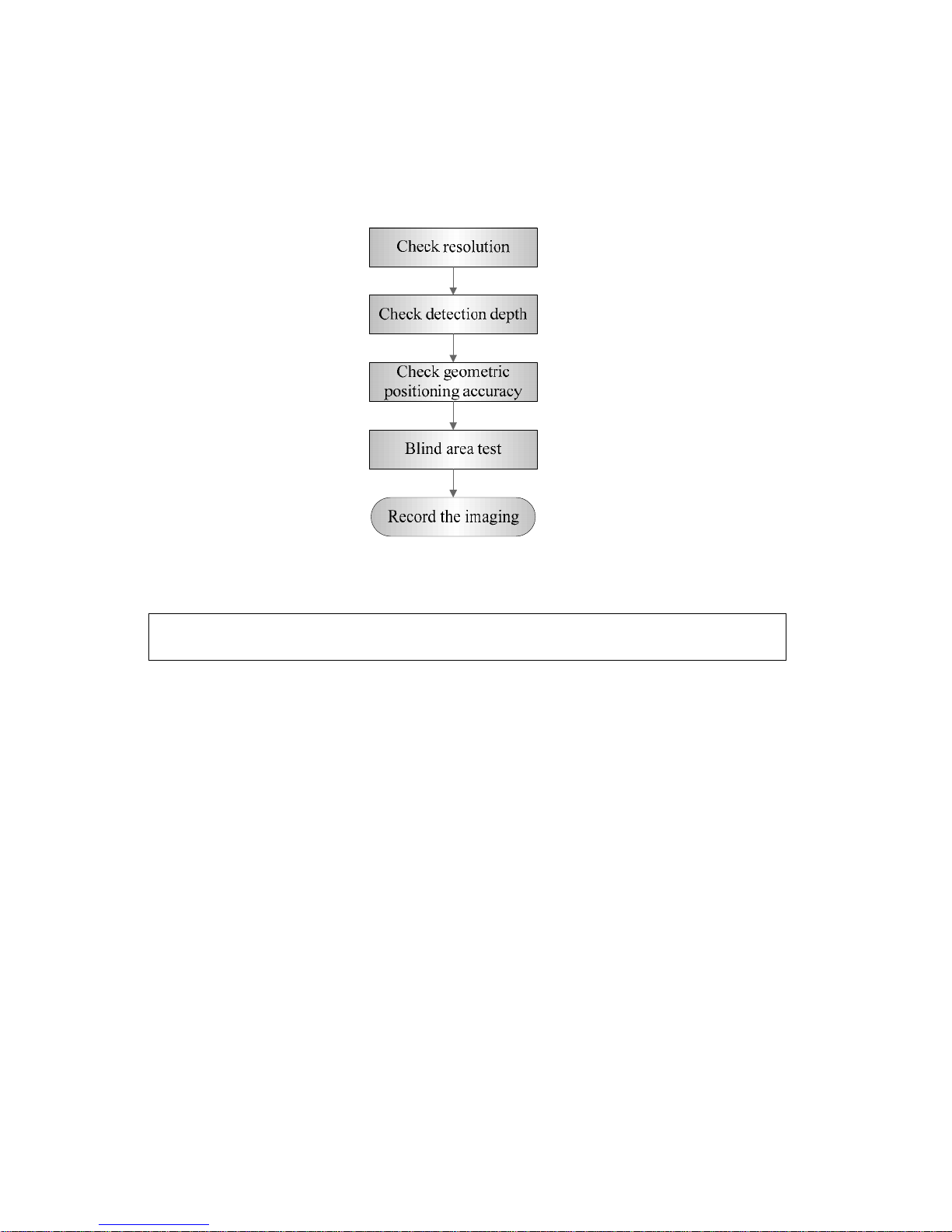
5-12 Checking Performance and Functions
5.5 Performance Test
5.5.1 Test Procedures
5.5.2 Test Content
Note:
The following figure is only used for reference in the testing, and the actual
image effect depends on the specific system.
Requirements:
1. Display: set the brightness and contrast values to clinical (or default) status;
2. Ambient: dark room to simulate actual clinical using;
3. The probe surface should contract with the acoustic window without separation or pressing.
Description:
Refer to <Appendix B Illustration or Phantom Using> for the phantoms used in the test.
Phantom KS107BD, low frequency, used when center frequency of the probe ≤ 4MHz;
Phantom KS107BG, high frequency, used when center frequency of the probe ≥5MHz;
5.5.2.1 Resolution
Lateral resolution
Test Procedure:
1. Place the probe head gently on the acoustic window of the phantom which is covered by water
or gel, and make sure the lateral resolution targets are displayed in the center of the image.
2. Focus to the lateral resolution target group.
3. Adjust gain, dynamic range, TGC, etc., make sure only the target line is displayed clearly on
the image with no tissue image in the background.
Page 87

Checking Performance and Functions 5-13
4. Read the separation between two target points that can be distinguished clearly, while keeping
the transverse target group horizontal.
5. Repeat upper steps at other depth.
Image effect is show in figure below:
Axial resolution
Test Procedure:
1. Place the probe head gently on the acoustic window of the phantom which is covered by water
or gel, and make sure the axial resolution targets are displayed in the center of the image.
2. Focus to the axial resolution target group.
3. Adjust gain, dynamic range, TGC, etc., make sure only the target line is displayed clearly on
the image with no tissue image in the background.
4. Read the distance between two target points that can be separated clearly.
5. Repeat upper steps at other depth.
Page 88
5-14 Checking Performance and Functions
Note:
1.
For convex probe, keep the lateral resolution targets near the central line of the
scanning plane.
2.
For linear probe with Steer function, DO NOT turn on Steer when testing the
transverse resolution.
3.
Magnify (zoom) the targets for observation if necessary.
4.
Distance between the left and right edges of a target point at a certain depth
indicates the transverse resolution at this depth also.
5.5.2.2 Maximum Detection Depth
Test Procedure:
1. Place the probe gently on the phantom surface which is covered by water or gel.
2. Set displaying depth (according to the max depth of the current probe);
3. Adjust Focus to the deepest value, set AP value to largest.
4. Increase Gain, Contrast, TGC, but make sure no halos or defocusing appears.
5. Record the depth of the most distant target line which is imaged clearly.
Note:
1.
An overlarge gain may result in large noise and submergence of the echo
signal.
2.
For linear probe, the probe surface should be perfectly fit with the acoustic
window on the phantom without any inclination during scan.
3.
For convex and phased probe, make sure the axial target group is placed in the
central of the scanning plane which keeps the justice of the interfering effect.
4.
In non-frozen mode, a distant target may be similar to a noise dot which should
be discarded.
Image effect is show in figure below:
Page 89

Checking Performance and Functions 5-15
5.5.2.3 Geometric Positioning Accuracy
Axial Geometric Positioning Accuracy
Test Procedure:
1. Adjusting steps are the same with the Maximum Detection Depth.
2. Record the separation values with measuring caliper in step of 20 mm on the axial target
group.
3. Select all measurement values deviating largely from 20 mm, and calculate the error by the
following formula.
Note:
1.
Measuring cursor should be placed on the top edge of the target image,
not in the middle or bottom edge.
2.
Scan plane should be perpendicular to each target line, in other words,
scan plane should be parallel to phantom section plane.
Image effect is show in figure below:
Page 90

5-16 Checking Performance and Functions
Lateral Geometric Positioning Accuracy
Test Procedure:
1. Place the probe gently on the acoustic window of phantom which is covered by water or gel.
2. Adjust display depth, to make horizontal groups display in the image.
3. Adjust focus to be in horizontal groups (no explicit standard).
4. Adjust gain, TGC, etc to make horizontal groups display clearly.
5. Use caliper to measure horizontal target distance by step of 20mm.
6. Select all measurement values deviating largely from 20 mm, and calculate the error by the
following formula.
Note:
1.
To linear array probe, read the lateral distance one segment after
another.
2.
For convex probe, display all lateral targets one time.
3.
The measurement caliper lies at the top or bottom of the target to be
measured.
Image effect is show in figure below:
Page 91

Checking Performance and Functions 5-17
5.5.2.4 Blind Area
Test Procedure:
1. Place the probe gently on the phantom surface which is covered by water or gel.
2. Adjust the depth to lower value and set the focus to shallowest.
3. Reduce AP, Gain, etc until the background noise is barely visible.
4. Observe the depth of shallowest target image. It is also the blind area value.
Note:
1.
For linear probe, the probe surface should be perfectly fit with the acoustic
window on the phantom without any inclination during scan.
2.
For convex probe, blind area target in the observation must lie on the central
line of the scan plane.
Image effect is show in figure below:
Page 92

Page 93

Software Installation & Maintenance 6-1
6 Software Installation &
Maintenance
6.1 Enter Maintenance
Note:
Before the maintenance operation, the engineer should login the system as Service.
Log-in:
1. When Access Control is disabled: press “ctrl”+“/” to pop up the Login dialogue box, select
Service as the user name and input the password.
2. When Access Control is enabled, press “ctrl”+“/” on the login dialogue box to show the inner
users, select Service and input the password to login.
3. Log in with the account of Service and press <Set up> to enter maintenance interface by
selecting [Preset]-[Maintenance]-[Setting].
Page 94
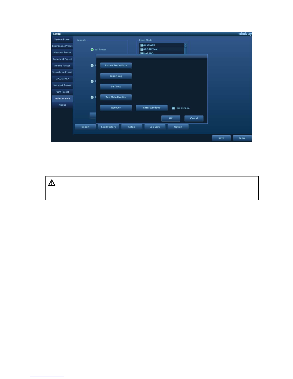
6-2 Software Installation & Maintenance
6.2 Software Installation/Restoration
See
Software Recovery Guide
for detailed system operations and Doppler system restoration.
6.3 Enter Windows
1. The password is generated by device Mac address and serial number (see System
Information), please contact Mindray Service Department for details.
2. Enter maintenance menu. Click [Enter Windows]. Type the password to enter Windows
system.
6.4 Software Maintenance
6.4.1 Log Export
1. Insert the USB disk to the device;
2. Enter [Setting] interface; select [Export Log] to export the log.
3. Select the path in the Browse page to save the log, and then click [OK].
WARNING:
1.
To avoid data loss, back up user’s preset data and patient data
before system restores.
2.
Do Not cut off, shut down or restart the system in the restoration.
Page 95

Software Installation & Maintenance 6-3
4. When the log is exported, the system prompts “Export succeed!”, click [OK] to return to
Maintenance menu.
Note:
The log can be exported to the external USB storage device only. Make sure
there is enough space for the storage before the exporting.
6.5 Data Backup and Storage
6.5.1 Preset Data Management
Select [Preset]-[Maintenance]. Export and import system preset data or load the factory.
6.5.1.1 Back up the Setup Data
1. Click [Export] to open the [Export Data] dialogue box on [Preset Data Management] interface.
2. Select the path to save data.
3. Click [OK]. A progress bar appears and the setup data of the selected item is exported to the
specified path.
6.5.1.2 Restore t he Setup Data
1. Click [Export] to open the [Export Data] dialogue box on [Preset Data Management] interface.
2. Select the path to import the data. Select path to import all data or some of the data;
3. Click [OK], a progress bar appears and the setup data is imported to the specified module.
Tip: If select [Load Factory], the settings are restored to the factory defaults, except for region
preset and admin.
Page 96

6-4 Software Installation & Maintenance
6.5.2 Patient Data Backup and Restoration
6.5.2.1 Patient Data Backup
1. Press [iStation] on the control panel to open the iStation dialogue box;
2. Click [Select All] to select all data or select the desired data one by one;
3. Select the information. Click [Backup Exam] to pop up the “Backup Patient Record” dialogue
box. Select the desired storage device (recorder, DVD or USB disk). Click [Backup]. Back up
the selected data automatically.
6.5.2.2 Restore Backup Patient Data
1. Press [iStation] on the control panel to open the iStation dialogue box;
2. Select the drive which contains the patient data. Click [Select All] to select all the data or select
the target data one by one. Click [Restore] to restore the patient data from the current drive to
the patient database.
6.6 Introduction on HDD Partition Data
1. The whole capacity is 128 G. The details are shown as follows:
Notes Blocks(G) Notes
C: 30G NTFS
D: 84G NTFS
E: 5.13G NTFS
2. Data distribution in each drive is shown as follows:
a) D drive
Data directory of Drive D Data Description
D:\M9
\StressEcho \UserProtocolTemplates StressEcho Protocol Template
\gui \word User-defined library
\PATIENTDATA \ Patient database path
\Preset \Current User preset data
\temporary \ Temporary file directory
\ScreenSaver Screensaver
\crash Dump file directory
\DICOMRevFiles Temporary file backed up by DICOM
\Log Log file
\DcmLog DICOM log
Userconfig User information file
b) E drive
Directory structure of saved data in E
Data Description
Page 97

Software Installation & Maintenance 6-5
Drive.
E:\M9 PatientBack Patient data backup
E: \Demo
Demo file
Page 98

Page 99

Field Replaceable Unit 7-1
7 Field Replaceable Unit
The chapter describes the detailed information of units, which can be replaced in the system scene.
Page 100

7-2 Field Replaceable Unit
7.1 Main Unit
No
.
Model
Classific
ation
Material Name Order Number
Picture
Remarks
Disassembl
y Referen ce
1
M9
series
Main unit
related
M9 Main Board
(FRU)
115-023067-00
Used for old
machine(LVDS
output+miniPCIEport
WiFi); Mark Software
version, Includes button
battery and radiator
washer.
8.2.10
115-033406-00
For M9GI in CE
region.Used for old
machine(LVDS
output+miniPCIEport
WiFi); MMark Software
version, Includes button
battery and radiator
washer.
M9 Main
Board(eDP
output+M.2 port
WiFi/FRU)
115-048332-00
Used for new machine
(eDP output+M.2 port
WiFi); Mark Software
version, Includes button
battery and radiator
washer.
8.2.10
M9 Main
Board(M9GI/eDP
output+M.2 port
WiFi/FRU)
115-048333-00
For M9GI in CE region.
Used for new machine
(eDP output+M.2 port
WiFi); Mark Software
version, Includes button
 Loading...