

Page 1
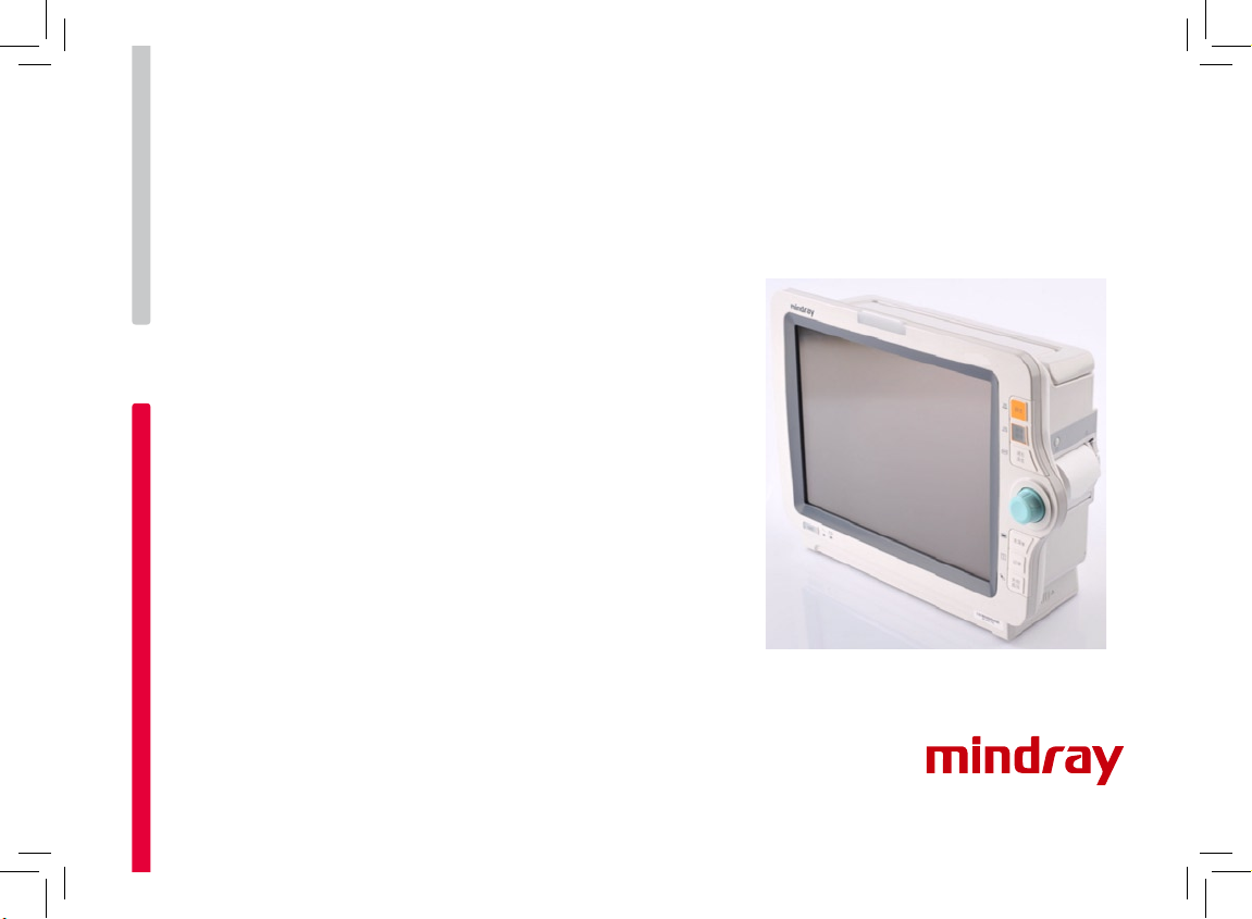
iMEC Series
Patient Monitor
Quick Guide
Page 2

© 2011 Shenzhen Mindray Bio-Medical Electronics Co., Ltd. All rights reserved.
Content in this guide is subject to change without prior notice.
Thank you for purchasing Mindray Patient Monitor.
We have included this convenient Quick Guide to help you with the basic operations. For
more details , please refer to the Operator’s Manual.
Note:
Before attempting to install, operate or adjust this product, please save and read the
Quick Guide completely.
This manual is based on the maximum conguration and therefore some contents may
not apply to your monitor. If you have any question, please contact us.
0123
Com ply with the re qui r eme nts of the
Council Directive 93/42/EEC.
Page 3
1
Product Overview
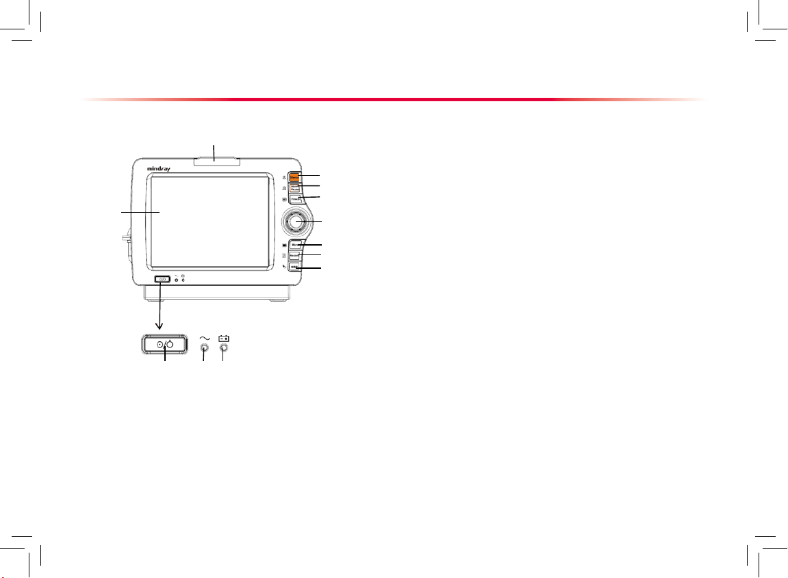
Front View
1. Power On/Off Switch
Press the switch to turn on the patient monitor. When the monitor is
on, pressing and holding this switch turns the patient monitor off. An
indicator is built in this switch. It turns on when the patient monitor is
on and turns off when the patient monitor is off.
2. AC power LED
It turns on when AC power is connected.
3. Battery LED
On: when the battery is installed and the AC source is connected.
Off: when no battery is installed or the installed battery is malfunction,
or no AC source is connected when the patient monitor is power
off.
Flash: when the patient monitor operates on battery power.
4. Alarm lamp
When a physiological alarm or technical alarm occurs, this lamp will
ash as dened below.
the lamp quickly ashes red.
the lamp slowly ashes yellow.
the lamp lights yellow without ashing.
5. Display Screen
6. Press to silence all alarm sounds.
7. Press to pause or restore alarms.
8. Press to freeze or unfreeze waveforms.
9. Knob
10. If no menu is displayed on the screen, pressing it enters the
main menu.
If there is a menu displayed on the screen, pressing it closes that
menu.
11. Press to start or stop recordings.
12. Press to start or stop NIBP measurements.
High level alarms:
Meidum level alarms:
Low level alarms:
6
7
8
9
10
11
12
1
2
3
5
4
Page 4
2
Product Overview
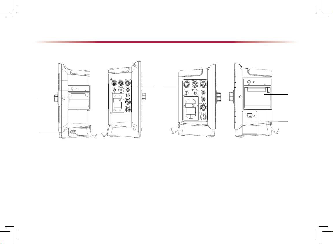
Side View (iMEC 12/iMEC 10)
3
1
2
1
2
1. Recorder
2. Battery compartment
3. Connectors for parameters
Side View (iMEC 8)
Page 5
3
Product Overview
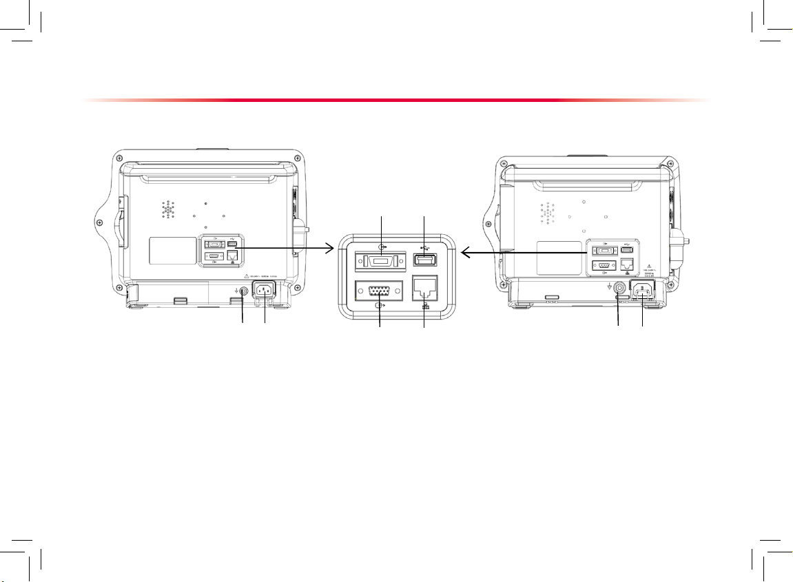
Rear View (iMEC8)Rear View (iMEC 12/iMEC 10)
1
1
2
2
43
5 6
1. Equipotential Grounding Terminal
2. AC Power Input
3. Multifunctional Connector
4. USB Connector
5. VGA Connector
6. Network Connector
Page 6

4
Basic Operations
Display Screen
1
2
3
4
5
9
6
Patient Information Area
Alarm Symbols
Technical Alarm Area
1.
2.
3.
4. Physiological Alarm Area
5. Waveform Area
6. Parameter Area A
7. Parameter Area B
8. Prompt Message Area
9. QuickKeys area
Select screen items by pressing them directly on the patient monitor’s screen.
You can lock or unlock the touchscreen
by pressing and holding the [Main Menu]
QuickKey for 3 seconds. The symbol is
displayed if the touchscreen is locked. In
this case, all touchscreen operations are
disabled.
Also, you can use the QuickKeys at the
bottom of the main screen to access fast
to functions.
Using the Touchscreen
8
7
Page 7

5
Basic Operations
Setting the Screen
You can enter the [Screen Setup] window as shown below by selecting the [Main Menu]→[Screen Setup]→[Screen Layout
>>]. In this window, you can allocate the positions of the parameters and waveforms. The parameters or waveforms whose
positions are not allocated will not be displayed.
Area A
Area B
Area C
The ECG parameter and the first ECG waveform always
display i n the fi rs t row. Th e configurable a reas ca n be
classied as Area A, Area B, and Area C.
In Area A, you can choose to display the parameters (having
waveforms) and their waveforms. Each parameter and the
associated waveform are displayed in the same row.
In Area B, you can choose to display the parameters and
their waveforms. When there is no parameter displayed in
area C, both the parameters and their waveforms will be
displayed in area B. Otherwise, only the parameters will be
displayed.
In Area C, you can choose to display all the parameters
whose associated waveforms will not be displayed.
The screen can automatically adjust to ensure the best view
based on your screen setup.
If no co rre sponding parameter or waveform is displa yed
on the monitor screen, you shoul d perform the following
inspections:
Check the connection of the lead, cable, or sensor.
Enter the [Screen Setup] window for the desired display
conguration.
Note
:
The parameters whose positions are not allocated in the
[Screen Setup] window will not be displayed. However, the
monitor can still give alarms of these parameters.
Page 8

6
To enter the main menu, select the [Main Menu] QuickKey on the monitor’s screen or the hardkey on the monitor’s
front. Most of monitor operations and settings can be performed through the main menu.
Basic Operations
Using the Main Menu
1
2
3
4
Other menus are similar to the main menu
and contain the following parts:
Heading: gives a sum-up for the current
menu.
Main body: displays options, buttons,
pr o mpt m ess a ge s , etc . The menu
button with “>>’’ enlarges a secondary
wi n dow t o rev e al more o pti ons or
information.
O n l i n e he l p area: di s p l a y s help
information for the screen item that the
cursor is positioned.
Select to exit the current menu.
1.
2.
3.
4.
Page 9

7
Getting Started
Turning Power On
Before you start to make measurements, check the patient
mo ni to r fo r any m ec ha ni cal da mage a nd m ak e sur e th at
all extern al cables, pl ug-ins and access ories are proper ly
connected.
Plug the power cord into the AC power source. If you run the
patient monitor on battery power, ensure that the battery is
sufciently charged.
Press the power on/off switch on the monitor’s front. The start-up
screens are displayed, and the alarm lamp is lit in yellow. Then,
the alarm lamp turns into red and turns off after the system gives
a beep.
The monitor enters the main screen.
Decide which measurements you want to make.
Connect the required patient cables and sensors.
Ch ec k th at t he p atient cab le s an d se nsors are correct ly
connected.
Check that the patient settings such as [Patient Cat.], [Paced],
etc, are appropriate for your patient.
Refer to the Operator's Manual for details of how to perform the
measurements you require.
1.
2.
3.
4.
1.
2.
3.
4.
5.
Starting Monitoring
Disconnecting from Power
To disconnect the patient monitor form the AC power
source, follow this procedure:
Conrm that the patient monitoring is nished.
Disconnect the patient cables and sensors from the
patient monitor.
Make sure to save or clear the patient monitoring
data as required.
Press and hold the power on/off switch. The patient
monitor shuts down and you can unplug the power
cable.
1.
2.
3.
4.
Note
:
Make sure that the operating environment of the
patient monitor meets the specic requirements.
Other wise unexpected consequ ences, e.g.
damage to the equipment, could result.
Do not use the patient monitor for any monitoring
procedure on a patient if you suspect it is not
working properly, or if it is mechanically damaged.
Contact your service personnel or us.
Basic Operations
Page 10

8
Basic Operations
Changing General Settings
Setting up a Monitor
In situations where you install a patient monitor or
change the patient monitor’s application site, you
need to setup the patient monitor as follows:
Select [Main Menu]→[Maintenance >>]→[User
Maintenance >>]→enter the required password.
In th e [Us e r M ain ten a nce ] m enu , s ele c t
[Monitor Name], [Department] and [Bed No.]
and change their settings.
Changing Language
Select [Main Menu]→[Maintenance >>]→[User
Maintenance >>]→enter the required password.
In the [U s e r M a int e n ance ] me n u, sel e c t
[Lan g u a g e] a n d th e n se l ect the desi r e d
language.
Restart the patient monitor.
Adjusting the Screen Brightness
Se le ct [Ma in M en u]→[S cr ee n Se tup >>]→
[Brightness].
Select the appropr iate setting fo r the scre en
brightness. 10 is the brightest, and 1 is the least
bright. When operated on the battery, you can set
a less bright screen to prolong the use time of the
battery. When the patient monitor enters standby
mode, the screen brightness will be adjusted to
the least bright automatically.
1.
2.
1.
2.
3.
1.
2.
Showing/Hiding the Help
The patient monitor provides online help information. The
user can display or hide the help as required.
Select [Main Menu]→[Screen Setup >>].
Select [Help] and toggle between [On] and [Off].
Setting the Date and Time
Select [Main Menu]→[Maintenance >>]→[System
Time >>].
Set the date and time.
Select [Date Format] and toggle between [yyyy-mm-
dd], [mm-dd-yyyy] and [dd-mm-yyyy].
Select [Time Format] and toggle between [24h] and
[12h].
1.
2.
1.
2.
3.
4.
Note
:
Changing date and time will af fect the storage of
trends and events and may cause data missing
.
Page 11

9
Basic Operations
Adjusting Volume
Alarm Volume
Select the [Alarm Setup] QuickKey→[Others], or
[Main Menu]→[Alarm Setup >>]→[Others].
Select [ A l m Vo l u m e ] an d th e n select t h e
ap pro pri ate vol u me : X -10 , in whic h X i s the
minimum volume, depending on the set minimum
alarm volume, and 10 the maximum volume.
Key Volume
Sel ect the [Volume Setup ] QuickKey, or [Main
Menu]→[Screen Setup >>].
Select [ K e y Vo l u m e ] an d then s e l e c t the
appropriate volume. 0 means off, and 10 is the
maximum volume.
QRS Volume
The QRS tone is derived from either the HR or PR,
depending on which is currently selected as the alarm
source in [ECG Setup] or [SpO2 Setup]. When monitoring SpO2, there is a variable pitch tone which changes
as the patient’s saturation level changes. The pitch of the
tone rises as the saturation level increases and falls as
the saturation level decreases. The volume of this tone
is user adjustable.
Select the [Volume Setup] QuickKey, or the ECG
parameter w indow→[Others >>], or the Sp O
2
parameter window.
Select
[QRS Volume] or
[Beat Vol] and then select
the appropriate volume. 0 means off, and 10 is the
maximum volume.
1.
2.
1.
2.
1.
2.
Managing Congurations
Entering the [Manage Conguration] Menu
Se l ect [ M ai n M enu ]→[ M ain ten anc e > >]→
[Manage Conguration >>].
Enter the required password and then select [Ok].
Setting Default Conguration
Select [Select Default Cong. >>] in the [Manage
Conguration] menu.
In the [Select D efault Confi g.] menu, select
[Load the Latest Config.] or [Load Specified
Cong.].
Saving Current Settings
Select [Save Current Settings As >>] in the
[Manage Conguration] menu.
In the popup dialog box, enter the conguration
name and then select [Ok].
Editing Conguration
Sel e c t [ E d it C o nfig . >> ] i n th e [ M a nage
Conguration] menu.
T h e p o pu p me n u s h o w s t h e e xi s ti n g
congurations on the monitor. Selecting [Cong.
on USB dr i ve > > ] w i ll s h ow the ex i stin g
configuration s on the USB drive. Select t he
desired configuration and then select the [Edit]
button.
1.
2.
1.
2.
1.
2.
1.
2.
Page 12

10
3. Select [Alarm Setup >>], [Screen Setup >>] or
[Parameter >>] to enter the corresponding menu
in which settings can be changed. The changed
items of alarm setup will be marked in red.
4. You can select [
Save] or [Save as] to save the
changed conguration. Select [Save] to overwrite
the original configuration. Select [Save as] to
save the changed conguration in another name.
Deleting a Conguration
Se le ct [De le te C on fig. >>] i n the [ Ma nage
Conguration] menu.
The popu p m enu sh ows the ex ist i ng us er
congurations on the monitor. Selecting [Cong.
on USB drive >>] will show the existing user
congurations on the USB drive. Select the user
congurations you want to delete and then select
[Delete].
Select [Yes] in the popup.
Transferring a Conguration
To export the current monitor’s conguration:
Connect the USB drive to the monitor’s USB port.
Se le ct [Ex po rt Confi g. >>] in t he [Mana ge
Conguration] menu.
In th e [ E xpor t C o nfig . ] m enu, se lec t the
congurations and [User Maintenance Settings]
to export . Then select th e [Exp ort] butt on. A
status mess age will repor t completio n o f the
transfer.
1.
2.
3.
1.
2.
3.
Basic Operations
To impor t the conguration on the USB drive to the
monitor:
1. Connect the USB drive to the monitor’s USB port.
2. Se le ct [
Im po rt C on fi g. > >] i n the [Ma na ge
Conguration] menu.
3. In th e [
Imp o rt C onf i g .] me n u, s ele c t t h e
congurations and [User Maintenance Settings]
to imp ort. Then selec t the [Import] b utton. A
status mess age will repor t completio n o f the
transfer.
Loading a Conguration
Select [Load Configuration >>] from the main
menu.
T h e p o pu p me n u s h o w s t h e e xi s ti n g
congurations on the monitor. Selecting [Cong.
on USB dr i ve > > ] w i ll s h ow the ex i stin g
congurations on the USB drive.
Select a desired conguration.
Select [View] to view the conguration details. In
the popup menu, you can select [Alarm Setup
>>], [Screen Setup >>] or [Parameter >>] to
view the corresponding contents. The alarm setup
items which are different than those currently
used are marked in red.
Select [Load] to load this conguration.
1.
2.
3.
4.
5.
Page 13

11
Record
The thermal recorder records patient information, measurement numerics, up to three waveforms, etc.
Starting and Stopping Recordings
To manually start a recording:
Select the hardkey on the front of either the patient monitor
or the recorder module.
Select the [Record] button from the current menu or window.
Automatic recordings will be triggered in the following conditions:
Timed recordings will start automatically at preset intervals.
If both [Alarm] and [Alm Rec] for a measurement are set on, an
alarm recording will be triggered automatically as alarms occur.
To manually stop a recording:
Select the hardkey again.
Se lec t [Cle ar All Tas ks] in t he
[Record Setup] menu.
Recordings stop automatically when:
The runtime is over.
The recorder runs out of paper.
When the recorder has an alar m
condition.
Page 14

Battery
The battery is charged whenever the patient monitor is connected to an AC power source
regardless of whether or not the patient monitor is currently on. Whenever the AC power is
interrupted during patient monitoring, the patient monitor will automatically run power from
the internal battery.
12
On-scre en battery symb ols indica te th e batt ery
status as follows:
Indicates that the battery works correctly. The solid portion represents the current
charge level of the battery in proportion to its maximum charge level.
Indicates that the battery has low charge level and needs to be charged. In this
case, the patient monitor provides an alarm message.
Indicates that the battery is almost depleted and needs to be charged immediately.
Otherwise, the patient monitor shuts down automatically.
Indicates that no battery is installed.
Note
:
Take out the battery before transpor t or storage to avoid damaging the battery.
Keep the battery out of the reach of children.
Use only the battery specied by the manufacturer.
Do not disassemble batter y, or dispose of it in re, or cause it to short circuit. It may ignite, explode, leak or
heat up, causing personal injury.
Page 15

Page 16

Shenzhen Mindray Bio-Medical Electronics Co., Ltd.
Mindray Building, Keji 12th Road South, Hi-tech Industrial Park,
Nanshan, Shenzhen 518057 P.R. China
Tel: +86 755 26582888
Fax: +86 755 26582680
www.mindray.com
 Loading...