

Mindray H-046-011262-00-N19-N22-Service-Manual-FDA-5.0 DIRECT FEED LOOP DISINFECTION TANK AND HEADER INSTALLATION & OPERATION MANUAL
Page 1

BeneVision N22/BeneVision N19
Patient Monitor
Service Manual
Page 2

Page 3

opyright 2018-2019 Shenzhen Mindray Bio-Medical Electronics Co., Ltd. All rights reserved.
C
Release time: January 2019
Revision 5.0
BeneVision N22/BeneVision N19 Patient Monitor Service Manual I
Page 4

Intellectual Property Statement
SHENZHEN MINDRAY BIO-MEDICAL ELECTRONICS CO., LTD. (hereinafter called Mindray) owns the intellectual property
rights to this product and this manual. This manual may refer to information protected by copyrights or patents and
does not convey any license under the patent rights of Mindray, nor the rights of others. Mindray does not assume any
liability arising out of any infringements of patents or other rights of third parties.
Mindray intends to maintain the contents of this manual as confidential information. Disclosure of the information in
this manual in any manner whatsoever without the written permission of Mindray is strictly forbidden. Release,
amendment, reproduction, distribution, rent, adaption and translation of this manual in any manner whatsoever
without the written permission of Mindray is strictly forbidden.
, is the trademark, registered or otherwise, of Mindray in China and other countries. All other trademarks
that appear in this manual are used only for editorial purposes without the intention of improperly using them. They are
the property of their respective owners.
This posting serves as notice under 35 U.S.C.§287(a) for Mindray patents: http://www.mindrayna.com/patents.
WARNING
Federal Law (USA) restricts this device to sale by or on the order of a physician or other practitioner
licensed by U.S. state law to use or order the use of this device.
NOTE
This manual describes all features and options. The equipment may not have all of them. Contact
Mindray Technical Support department for any questions.
II BeneVision N22/BeneVision N19 Patient Monitor Service Manual
Page 5

Manufacturer’s Responsibility
Contents of this manual are subject to changes without prior notice.
Mindray is responsible for safety, reliability and performance of this product only on the condition that:
All installation operations, expansions, changes, modifications and repairs of this product are conducted by
Mindray authorized personnel;
The electrical installation of the relevant room complies with the applicable national and local requirements;
This product is operated under strict observance of the operator’s manual.
Return Policy
In the event that it becomes necessary to return a unit to Mindray, follow the instructions below.
1. Obtain a return authorization.
Contact the Mindray Service Department and obtain a Mindray Customer Service Authorization Number. The
Mindray Customer Service Authorization Number must appear on the outside of the shipping container. Return
shipments will not be accepted if the Mindray Customer Service Authorization Number is not clearly visible. Please
provide the model number, serial number, and a brief description of the reason for return.
2. Freight policy
The customer is responsible for freight charges when this product is shipped to Mindray for service (including any
relevant customs fees or other freight related charges).
3. Return address
Please send the part(s) or equipment to the address offered by Customer Service Department.
BeneVision N22/BeneVision N19 Patient Monitor Service Manual III
Page 6

Service
Mindray maintains a network of service representatives and factory-trained distributors. Prior to requesting service,
perform a complete operational check of the instrument to verify proper control settings. If operational problems
continue to exist, contact Mindray service.
In North America contact the Service Department at (800) 288-2121, ext: 8116 for Technical Support or (201) 995-8000
for assistance in determining the nearest field service location.
Please include the instrument model number, the serial number, and a description of the problem with all requests for
service.
Any questions regarding the warranty should be directed to your local sales or service representative.
NOTE
Upon request, Mindray provides circuit diagrams, component part lists, descriptions, calibration
instructions, or other information which assist the user’s appropriately qualified technical
personnel to repair those parts of the equipment which are designated by Mindray DS USA, Inc. as
repairable.
Contact Information
Manufacturer:
Address:
Tel:
Fax:
Website:
Distributor:
Address:
Tel:
Website:
Shenzhen Mindray Bio-Medical Electronics Co., Ltd.
Mindray Building, Keji 12th Road South, High-tech Industrial Park, Nanshan, Shenzhen
518057 P.R. China
+86 755 81888998
+86 755 26582680
www.mindray.com
Mindray DS USA, Inc.
800 MacArthur Boulevard, Mahwah, New Jersey 07430 USA
1.800.288.2121, 1.201.995.8000
www.mindray.com
IV BeneVision N22/BeneVision N19 Patient Monitor Service Manual
Page 7

Preface
Manual Purpose
This manual provides detailed information about the assembly, disassembly, testing and troubleshooting of the
equipment to support effective troubleshooting and repair. It is not intended to be a comprehensive, in-depth
explanation of the product architecture or technical implementation. Use of the manual is necessary for proper
equipment maintenance and will help to eliminate equipment damage and personal injury.
This manual is based on the maximum configuration; therefore, some contents may not apply to your monitor. If you
have any question, please contact our Customer Service Department.
Intended Audience
This manual is for biomedical engineers, authorized technicians or service representatives responsible for
troubleshooting, repairing and maintaining the patient monitors.
Contact your local Mindray Service Organization for information on product courses which address service and support
for this product.
Passwords
A password may be required to access different modes within the monitor. The passwords are listed below:
User maintenance: MIN888 (User adjustable)
Configuration mode: MIN315 (User adjustable)
It is recommended that the user should change the passwords for user maintenance and configuration mode once they
take ownership of the equipment.
BeneVision N22/BeneVision N19 Patient Monitor Service Manual V
Page 8

FOR YOUR NOTES
VI BeneVision N22/BeneVision N19 Patient Monitor Service Manual
Page 9

Contents
1 Safety ................................................................................................................................................................................. 1-1
1.1 Safety Information .......................................................................................................................................................................................... 1-1
1.1.1 DANGER ................................................................................................................................................................................................ 1-2
1.1.2 Warnings .............................................................................................................................................................................................. 1-2
1.1.3 Cautions ............................................................................................................................................................................................... 1-2
1.1.4 Notes ..................................................................................................................................................................................................... 1-2
1.2 Equipment Symbols ....................................................................................................................................................................................... 1-2
2 Operation Theory .............................................................................................................................................................. 2-1
2.1 Overview ............................................................................................................................................................................................................ 2-1
2.2 Product System Architecture ...................................................................................................................................................................... 2-1
2.2.1 Functions of the Main Control Module ..................................................................................................................................... 2-3
2.2.2 AC-DC Module ................................................................................................................................................................................... 2-4
2.2.3 Functions and Socket Definitions of the DCDC Board ........................................................................................................ 2-4
2.2.4 Front Housing Interface Board ..................................................................................................................................................... 2-7
2.2.5 iView Substrate .................................................................................................................................................................................. 2-8
2.3 Power System ................................................................................................................................................................................................... 2-8
2.3.1 Power Diagram of the Main Unit and the Module Rack ..................................................................................................... 2-8
2.3.2 The Secondary Screen of N22/N19 Uses Independent AC Adapter for Power Supply ............................................ 2-9
2.4 Signal Logic Flow ............................................................................................................................................................................................ 2-9
2.4.1 Startup Signal Flow .......................................................................................................................................................................... 2-9
2.4.2 Display Signal Flow ....................................................................................................................................................................... 2-10
2.4.3 Display Brightness Control ......................................................................................................................................................... 2-11
2.4.4 Module Initialization ..................................................................................................................................................................... 2-12
3 Testing and Maintenance .................................................................................................................................................. 3-1
3.1 Introduction ...................................................................................................................................................................................................... 3-1
3.1.1 Test Equipment .................................................................................................................................................................................. 3-1
3.1.2 Preventative Maintenance ............................................................................................................................................................. 3-1
3.1.3 Recommended Frequency ............................................................................................................................................................ 3-2
3.2 Preventative Maintenance Procedures ................................................................................................................................................... 3-3
3.2.1 Visual Inspection ............................................................................................................................................................................... 3-3
3.2.2 NIBP Tests ............................................................................................................................................................................................. 3-4
3.2.3 Sidestream and Microstream CO2 Tests .................................................................................................................................... 3-6
3.2.4 AG Tests ................................................................................................................................................................................................ 3-8
3.3 Power On Test ................................................................................................................................................................................................ 3-11
3.4 Module Performance Tests ....................................................................................................................................................................... 3-11
3.4.1 ECG Tests ........................................................................................................................................................................................... 3-11
3.4.2 Resp Performance Test ................................................................................................................................................................. 3-12
3.4.3 SpO2 Test ........................................................................................................................................................................................... 3-12
3.4.4 NIBP Tests .......................................................................................................................................................................................... 3-12
3.4.5 Temp Test .......................................................................................................................................................................................... 3-13
3.4.6 IBP Tests ............................................................................................................................................................................................. 3-13
BeneVision N22/BeneVision N19 Patient Monitor Service Manual 1
Page 10

3.4.7 C.O. Test .............................................................................................................................................................................................. 3-15
3.4.8 Sidestream and Microstream CO2 Tests ................................................................................................................................... 3-15
3.4.9 AG Tests ................................................................................................................................................................................................ 3-15
3.4.10 EEG Test ............................................................................................................................................................................................ 3-15
3.4.11 BIS Test .............................................................................................................................................................................................. 3-17
3.4.12 CCO/SvO2 Tests ............................................................................................................................................................................... 3-17
3.4.13 NMT Tests ......................................................................................................................................................................................... 3-18
3.5 Nurse Call Relay Performance Test ......................................................................................................................................................... 3-19
3.6 Analog Output Performance Test ........................................................................................................................................................... 3-19
3.7 Electrical Safety Tests .................................................................................................................................................................................. 3-20
3.8 Recorder Check ............................................................................................................................................................................................. 3-20
3.9 Network Print Test ........................................................................................................................................................................................ 3-21
3.9.1 Device Connection and Setup ................................................................................................................................................... 3-21
3.10 Battery Check .............................................................................................................................................................................................. 3-21
3.11 Mounting Check ......................................................................................................................................................................................... 3-22
3.11.1 Safety check ................................................................................................................................................................................... 3-22
3.11.2 Overall Test and Check of Installed System ........................................................................................................................ 3-22
4 Troubleshooting ................................................................................................................................................................ 4-1
4.1 Introduction ..................................................................................................................................................................................................... 4-1
4.2 Part Replacement ........................................................................................................................................................................................... 4-1
4.3 Check before Powering on the Monitor ................................................................................................................................................. 4-1
4.4 Software Version Check ................................................................................................................................................................................ 4-1
4.5 Technical Alarm Check .................................................................................................................................................................................. 4-2
4.6 Blank Screen upon Startup ......................................................................................................................................................................... 4-2
4.7 Troubleshooting Guide ................................................................................................................................................................................ 4-3
4.7.1 Power On/Off Failures ..................................................................................................................................................................... 4-3
4.7.2 Display Failures .................................................................................................................................................................................. 4-4
4.7.3 Module Rack Failures ...................................................................................................................................................................... 4-5
4.7.4 Alarm Failures .................................................................................................................................................................................... 4-6
4.7.5 Output Interface Failures ............................................................................................................................................................... 4-7
4.7.6 Power Supply Failures ..................................................................................................................................................................... 4-7
4.7.7 Network Related Problems ........................................................................................................................................................... 4-8
4.7.8 Device Integration Failures ........................................................................................................................................................... 4-9
5 Hardware Configuration Options .................................................................................................................................... 5-1
5.1 Overview ........................................................................................................................................................................................................... 5-1
5.2 Optional Parameter Function Modules .................................................................................................................................................. 5-2
5.3 Optional Functional Assemblies ............................................................................................................................................................... 5-3
5.3.1 Installing an SMR .............................................................................................................................................................................. 5-3
5.3.2 Installing an Secondary Display .................................................................................................................................................. 5-3
5.3.3 Upgrading Split Unit ....................................................................................................................................................................... 5-4
5.3.4 Setting up Wireless Network Functions ................................................................................................................................... 5-4
5.3.5 Upgrading Handle Assembly ....................................................................................................................................................... 5-4
5.3.6 Installing the Main Unit Battery .................................................................................................................................................. 5-4
2 BeneVision N22/BeneVision N19 Patient Monitor Service Manual
Page 11

5.3.7 Upgrading iView System Functions ........................................................................................................................................... 5-4
6 Disassembly and Repair.................................................................................................................................................... 6-1
6.1 Tools ..................................................................................................................................................................................................................... 6-1
6.2 Preparations for Disassembly ..................................................................................................................................................................... 6-1
6.3 Whole Unit Disassembly ............................................................................................................................................................................... 6-1
6.3.1 Disassembling Display and Main Unit (Main Unit and Display Integrated Installation) ......................................... 6-2
6.3.2 Removing Handle/Encoder (Optional Encoder) .................................................................................................................... 6-3
6.3.3 Removing Handle Cover ................................................................................................................................................................ 6-4
6.3.4 Removing Main Unit Housing/Main Unit Interface Adapter Board (Main Unit and Display Separated
Installation) .................................................................................................................................................................................................... 6-4
6.3.5 Removing Display Interface Adapter Board (Main Unit and Display Separated Installation) ............................... 6-5
6.4 Disassembling Display (Capacitive Touchscreen) ............................................................................................................................... 6-6
6.4.1 Removing Display Rear Housing Assembly (D19)................................................................................................................. 6-6
6.4.2 Removing Display Rear Housing Assembly (D22)................................................................................................................. 6-7
6.4.3 Removing Switch Keypad Board ................................................................................................................................................. 6-7
6.4.4 Removing Display Interface Board/Touchscreen Panel ...................................................................................................... 6-8
6.4.5 Removing USB Board ...................................................................................................................................................................... 6-9
6.4.6 Removing LED Board/Indicator Board ................................................................................................................................... 6-10
6.5 Disassembling Main Unit .......................................................................................................................................................................... 6-10
6.5.1 Removing iView Assembly (iView Assembly Optional).................................................................................................... 6-10
6.5.2 Removing iView Assembly Support Board/USB Interface Board (iView Assembly Optional) ........................... 6-11
6.5.3 Removing Battery .......................................................................................................................................................................... 6-11
6.5.4 Removing ACDC Power Board .................................................................................................................................................. 6-12
6.5.5 Removing DCDC Power Management Board ...................................................................................................................... 6-13
6.5.6 Removing Antenna Module and Antenna Cable ............................................................................................................... 6-13
6.5.7 Removing SSD Hard Disk ............................................................................................................................................................ 6-14
6.5.8 Removing Main Control Board .................................................................................................................................................. 6-14
6.5.9 Removing Battery Backplane .................................................................................................................................................... 6-15
6.6 Disassembling the Module Rack ............................................................................................................................................................ 6-15
6.6.1 Disasembling the Handle and Hooks ..................................................................................................................................... 6-15
6.6.2 Disassembling the Rear Case of Module Rack..................................................................................................................... 6-16
6.6.3 Disassembling the Module Rack Interface Board .............................................................................................................. 6-16
6.6.4 Disassembling the Infrared Backplane of Module Rack .............................................................................................. 6-17
6.7 Disassembling the M51C Module .......................................................................................................................................................... 6-18
6.7.1 Disassembling the Front Panel Assembly ............................................................................................................................. 6-18
6.7.2 Disassembling the Parameter Board ...................................................................................................................................... 6-18
6.7.3 Disassembling the SpO2 board ................................................................................................................................................ 6-19
6.7.4 Disassembling the Infrared Board ........................................................................................................................................... 6-19
6.7.5 Removing the Pump and Valve................................................................................................................................................. 6-19
7 Parts ................................................................................................................................................................................... 7-1
7.1 Main Unit ........................................................................................................................................................................................................... 7-1
7.1.1 Exploded View .................................................................................................................................................................................... 7-1
7.1.2 Parts List ............................................................................................................................................................................................... 7-1
7.2 D19 Display Assembly (Capacitive Screen) ........................................................................................................................................... 7-3
BeneVision N22/BeneVision N19 Patient Monitor Service Manual 3
Page 12

7.2.1 Exploded View .................................................................................................................................................................................... 7-3
7.2.2 Parts List ............................................................................................................................................................................................... 7-3
7.3 D22 Display Assembly (Capacitive Screen) ........................................................................................................................................... 7-5
7.3.1 Exploded View .................................................................................................................................................................................... 7-5
7.3.2 Parts List ............................................................................................................................................................................................... 7-5
7.4 Encoder Assembly .......................................................................................................................................................................................... 7-7
7.4.1 Exploded View .................................................................................................................................................................................... 7-7
7.4.2 Parts List ............................................................................................................................................................................................... 7-7
7.5 Module Rack ..................................................................................................................................................................................................... 7-8
7.5.1 Exploded View .................................................................................................................................................................................... 7-8
7.5.2 Parts List ............................................................................................................................................................................................... 7-8
7.6 iVIEW Module ................................................................................................................................................................................................... 7-9
7.6.1 Exploded View .................................................................................................................................................................................... 7-9
7.6.2 Parts List ............................................................................................................................................................................................... 7-9
7.7 Main Unit Separated Installation Auxiliary Accessories ................................................................................................................. 7-10
7.7.1 Exploded View .................................................................................................................................................................................. 7-10
7.7.2 Parts List ............................................................................................................................................................................................. 7-10
7.8 Main Unit Base Assembly .......................................................................................................................................................................... 7-11
7.8.1 Exploded View .................................................................................................................................................................................. 7-11
7.8.2 Parts List ............................................................................................................................................................................................. 7-11
7.9 Battery Cavity Assembly ............................................................................................................................................................................ 7-13
7.9.1 Exploded View .................................................................................................................................................................................. 7-13
7.9.2 Parts List ............................................................................................................................................................................................. 7-13
7.10 M51C Module .............................................................................................................................................................................................. 7-14
7.10.1 Exploded View ............................................................................................................................................................................... 7-14
7.10.2 Parts List .......................................................................................................................................................................................... 7-14
A Electrical Safety Inspection .............................................................................................................................................. A-1
A.1 Power Cord Plug ............................................................................................................................................................................................. A-1
A.2 Device Enclosure and Accessories ........................................................................................................................................................... A-1
A.3 Device Labelling ............................................................................................................................................................................................. A-2
A.4 Scheduled Electrical Safety Inspection .................................................................................................................................................. A-2
A.5 Electrical Safety Inspection after Repair ................................................................................................................................................ A-2
A.6 Electrical Safety Inspection Tes t ................................................................................................................................................................ A-3
4 BeneVision N22/BeneVision N19 Patient Monitor Service Manual
Page 13

1 Safety
DANGER
1.1 Safety Information
Indicates an imminent hazard that, if not avoided, will result in death or serious injury.
WARNING
Indicates a potential hazard or unsafe practice that, if not avoided, could result in death or serious
injury.
CAUTION
Indicates a potential hazard or unsafe practice that, if not avoided, could result in minor personal injury
or product/property damage.
NOTE
Provides application tips or other useful information.
BeneVision N22/BeneVision N19 Patient Monitor Service Manual 1-1
Page 14

1.1.1 DANGER
There are no dangers that refer to the product in general. Specific “Danger” statements may be given in the respective
sections of this manual.
1.1.2 Warnings
WARNING
All installation operations, expansions, changes, modifications and repairs of this product should be
conducted by Mindray authorized personnel.
There is high voltage inside the equipment. Never disassemble the equipment before it is disconnected
from the AC power source.
When you disassemble/reassemble a parameter module, a patient leakage current test must be
performed before it is used again for monitoring.
The equipment must be connected to a properly installed power outlet with protective earth contacts
only. If the installation does not provide for a protective earth conductor, disconnect it from the power
line and operate it on battery power, if possible.
Dispose of the package material, observing the applicable waste control regulations and keeping it out
of children’s reach.
1.1.3 Cautions
CAUTION
Make sure that no electromagnetic radiation interferes with the performance of the equipment when
preparing to carry out performance tests. Mobile phone, X-ray equipment or MRI devices are a possible
source of interference as they may emit higher levels of electromagnetic radiation.
Before connecting the equipment to the power line, verify the voltage and frequency ratings of the
power line are the same as those indicated on the equipment’s label or in this manual.
Protect the equipment from damage caused by drop, impact, strong vibration or other mechanical force
during servicing.
1.1.4 Notes
NOTE
Refer to Operation Manual for detailed operation and other information.
1.2 Equipment Symbols
See the N series Operator’s Manual (P/N: 046-011259-00) for information about the symbols used on this product and its
packaging.
1-2 BeneVision N22/BeneVision N19 Patient Monitor Service Manual
Page 15

2 Operation Theory
2.1 Overview
TheN22/N19 patient monitor provides rich functionality to monitor patient’s vital signs including ECG, Resp, SpO2, Temp,
N IB P, I B P, CO
monitor supports alarm management, data review, recording and printing of patient reports, and calculation.
TheN22/N19 patient monitor is applicable to various departments in a hospital, in particular, to the applications in
intensive care, first aid, operation room and the relevant departments.
The N22/N19patient monitor provides clinical decision-making tools to assist the medical personnel in making diagnosis
and clinical judgment faster and more accurately. Information access to clinical information system can meet the
information requirements of doctors and nurses so as to shorten the time of obtaining information and analyze the
clinical experience. These features could better meet the application requirements of high-end users.
, AG, O2, RM, C.O., CCO, ICG, SvO2/ScvO2, BIS, EEG, NMT, tcGas and rSO2. Based on these parameters, the
2
2.2 Product System Architecture
N22/N19 monitor mainly consists of three parts: main unit, display and module rack. All-in-one installation or split-type
installation could be adopted for the main unit and the display.
BeneVision N22/BeneVision N19 Patient Monitor Service Manual 2-1
Page 16

ACDC
Power manage Board& interface board
Bay Trail Main
Board
Front Interface Board
For Integrate Type
Battery Interface
Board
WiFi
Module
Battery
LCD
Resistive
Touch
Panel
Speaker
Alarm
&logo LED
Board
Resistive
Touch Panel
Controller
Board
W1
W4
Backlight
LVDS
Remote
Receiver
(Reserved)
Touchpad&
knob&USB
Indicator
LED
Power
Button
W3
WD
W
2
DP USB NET
UART2 STATUS
UART1
W6
W8
SMR
SMR
SMR
W7
The main PCBAs of the system include:
Main unit: DCDC and interface board, ACDC board, and main board and interface board.
Display: display interface board
Module rack: Module rack interface board, and 8-slot module rack communication board.
2-2 BeneVision N22/BeneVision N19 Patient Monitor Service Manual
Page 17
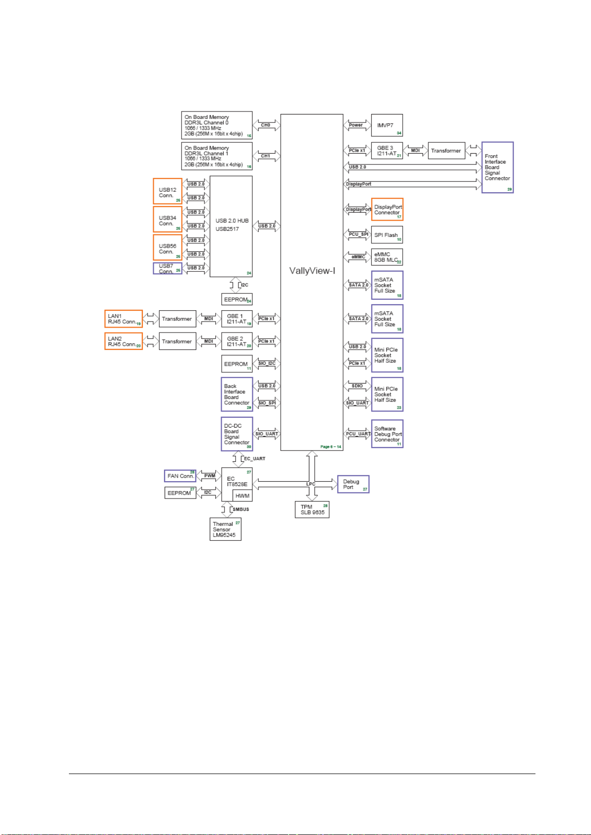
2.2.1 Functions of the Main Control Module
The main board is supported by the Bay Trail platform and uses Intel’s Bay Trail-I E38xx series processors.
Architecture of the Main Board
As the core control unit of the system, the main board is responsible for such core functions of the system as display,
data processing and data storage.
The main board also provides high-speed interfaces, such as USB connector, DP interface and network connector.
BeneVision N22/BeneVision N19 Patient Monitor Service Manual 2-3
Page 18

2.2.2 AC-DC Module
The ACDC module converts the input voltage of 100~240V 50/60Hz AC into the output of 16V 10A DC.
2.2.3 Functions and Socket Definitions of the DCDC Board
2.2.3.1 Functions of the DCDC Board
The DCDC board is responsible for the conversion of the data signal of the main board into the external interface and is
responsible for generating the various DC voltages the hardware system requires and for implementing the power
management function. The major functions include:
Generation and management of 12V, 5V, 3.3V, Vbus and 3.3VB power supply required for the system operation;
Extension of connectors such as SMR;
Monitor startup and shutdown;
Battery management;
2.2.3.2 Definitions of the DCDC Board Socket
The DCDC board is the core for connecting other PCBAs inside the main unit, and the main sockets include:
16V DC input power socket used for connecting to the ACDC board
Connector Type B6PH-VS
Pin No. Signal Name Signal Direction Function Definition Remarks
1 16V IN DC input /
2 16V IN DC input /
3 16V IN DC input /
4 GND / Ground /
5 GND / Ground /
6 GND / Ground /
2-4 BeneVision N22/BeneVision N19 Patient Monitor Service Manual
Page 19

Power connector of the battery interface board
Used for connecting the charging and discharging power of the battery interface board.
Connector Type B4PS-VH
Pin No. Signal Name Signal Direction Function Definition Remarks
1 GND / Ground /
2 BAT BI Battery power /
3 BAT BI Battery power /
4 GND / Ground /
Signal connector of the battery interface board
Used for connecting the battery availability signal and SMB signal of the battery interface board.
Connector Type B3B-PH-K-S
Pin No. Signal Name Signal Direction Function Definition Remarks
1 BAT_BC IN Battery availability signal /
2 SMB_D BI SMBus data signal /
3 SMB_C OUT SMBus clock signal /
Power connector of the main board
Used for connecting the main board to provide 3.3V, 5V and 16V DC power to the main board.
Connector Type 43045-0800
Pin No. Signal Name Signal Direction Function Definition Remarks
1 3.3V OUT DC output /
2 5V OUT DC output /
3 5V OUT DC output /
4 16V OUT DC output /
5 GND / Ground /
6 GND / Ground /
7 GND / Ground /
8 GND / Ground /
BeneVision N22/BeneVision N19 Patient Monitor Service Manual 2-5
Page 20

Signal connector of the main board
Used for connecting the main board, including SPI, USB, UART, reset, power indicator and management signals.
Connector Type 5015714007
Pin No. Signal Name Signal Direction Function Definition Remarks
1 GND / Ground /
2 GND / Ground /
3 USB_DP BI USB D+ /
4 SPI_LVDS_CLKP IN SPI differential clock Reserved
5 USB_DM BI USB D- /
6 SPI_LVDS_CLKP IN SPI differential clock Reserved
7 GND / Ground /
8 GND / Ground /
9 USB_Hub_RST# IN USB Hub reset /
10 SPI_CLK IN SPI clock /
11 FPGA_RST# IN FPGA reset /
12 GND / Ground /
13 NC / No signal connection /
14 SPI_MOSI IN Primary output of SPI /
15 NC / No signal connection /
16 GND / Ground /
17 NC / No signal connection /
18 SPI_MISO OUT Secondary output of SPI /
19 NC / No signal connection /
20 GND / Ground /
21 GND / Ground /
22 SPI_CS# IN SPI chip select /
23 EC_S3# IN S3 power status /
24 SPI_CTL1 IN GPI /
25 EC_S4# IN S4 power Status /
26 SPI_CTL2 OUT GPO /
27 PLTRST#_Report IN CPU reset status /
28 EC_RST#_Report IN EC reset status /
29 AC_BC OUT AC availability /
30 GND / Ground /
31 Battery_Yellow OUT
32 M0_TXD OUT M0 UART sending /
33 Battery_Green OUT
34 M0_RXD IN M0 UART receiving /
35 PWROK OUT Power supply status /
36 NC / No signal connection /
37 PWR_BTN# OUT Main control startup and /
2-6 BeneVision N22/BeneVision N19 Patient Monitor Service Manual
Battery driven by yellow
LED
Battery driven by green
LED
/
/
Page 21

Connector Type 5015714007
Pin No. Signal Name Signal Direction Function Definition Remarks
shutdown
38 NC / No signal connection /
39 GND / Ground /
40 GND / Ground /
DC power output connector of the main unit
Used by the main unit for providing 12V power supply to the display.
Connector Type 43045-0409
Pin No. Signal Name Signal Direction Function Definition Remarks
1 12V OUT DC output /
2 12V OUT DC output Reserved
3 GND / Ground Reserved
4 GND / Ground /
2.2.4 Front Housing Interface Board
The front housing interface board and its peripheral circuits are mainly used for realizing the control of the alarm LED,
LOGO LED, backlight and audio, as well as the detection and transmission of the touchscreen, encoder and ambient
light.
As the front housing interface boardhas much to control, a microcontroller unit (MCU) is used for the central control. The
MCU is connected to the main control of the system through the DisplayPort AUX channel (DP AUX), and the USB
connection channel is reserved.
BeneVision N22/BeneVision N19 Patient Monitor Service Manual 2-7
Page 22

��5V
iPC support board
COME Type10
i
P
C
C
o
n
n
RJ45
m
S
A
T
A
SATA0
Conn
GbE
USB0
UART
0
HDMI
TMDS
HDMI to
MIPI-CSI2
CSI2 x4 Lane
16V
Power
Managment
PWR_BTN#
RST#
FAN
FAN
Control
FAN
Contro
l
5VCC
5VSB
Power
Switch
16V_iPC
SUS_S4#
16V Over
Current
Protection
3.3V DC-DC
5V DC-DC
Always on
VDD
5VSB
Power
Switch
SUS_S3#
5VCC
BD_16V
SUS_S3#
16V
SUS_S3#
BD_16V_OC#
BD_16V_EN
iPC_BC#
Connect
to GND
PCIe Port0
PCIe
GbE
MAC
/PHY
(I211-AT)
GbE
Debug
� Reserved�
TPM
Level
Shifter
TMDS
DDC
DDC
I2C
EEPROM
EDID
5VSB
16V
VDD_PG
&
0
0
0
SUS_S3#
VDD_PG
SUS_S3#
PWR_OK
Conn
USB Type A
Connector x
4
USB Hub
(USB2517
)
USB x 4
USB
CB_RST
#(COME)
RST#
BEEP
SPKR
LCD
backlight
Alarm LED
board
USB
12V
12V
12V
LCD
5V
5V
CPU
CPU of
main
control
5V@5
.2A
3.3V
Main board
Display interface board
Slow
start
power
Slow start
power
Power
Supply
DCDC
5V
3.3V
3
.3VLDO
MCU� M0�
12V
_EN
5
V_EN
3
.3V
_EN
DCDC board
4mA(Typ)
AC-
DC
board
Charging and
discharging
management
LED
DCDC
12V
12V
3.3V
VBUS
_EN
Charging
circuit
3.3V
Hot swap
circuit
Hot swap
circuit
Hot swap
circuit
Module rack1
Module rack3
12
V
12V
VBUS:
10V-
16V/140W(MAX)
16
V
iView module
12V
12V
EN
12V
12V
Module rack2
12V
12V
DCDC board
2.2.5 iView Substrate
iView substrate is mainly used to carry the COME module (COM Express module), extending the function of the COME to
standard interfaces as well as communication signals with the main board.
The COME module uses Type10 module (mechanical size: 55 mm x 84 mm) as defined in the specifications, and the
connection with the main board could be realized with one 220pin socket.
2.3 Power System
2.3.1 Power Diagram of the Main Unit and the Module Rack
The power management MCU is the core of the power management. In the system, 3.3V STB output could be realized
with any power input (AC or battery), which means that the power management MCU works properly. The display
interface board and module rack of the front housing could directly use the system's 12V power supply.
2-8 BeneVision N22/BeneVision N19 Patient Monitor Service Manual
Page 23

N22/N19 System
Primary
display
(split type)
Secondary
display
Main unit
AC adapter of
the secondary
display
AC power 1
AC power 2
Only signals, no power supply
User
Battery
Primary display
(all-in-one)
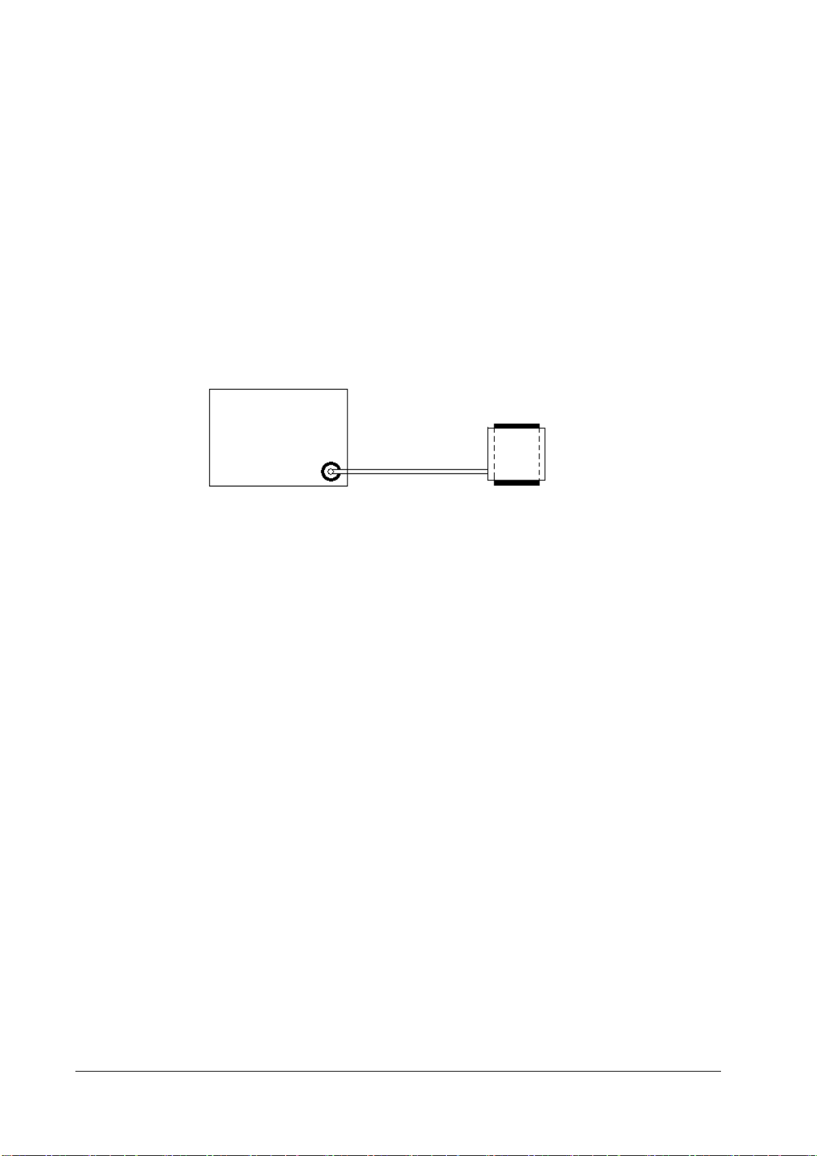
2.3.2 The Secondary Screen of N22/N19 Uses Independent AC Adapter for Power Supply
The connection is as shown below:
The battery is in the main unit, and the secondary screen is connected to the adapter. The primary and secondary
display controls are independent of each other, allowing the secondary display to be turned on or off without affecting
the complete system.
2.4 Signal Logic Flow
2.4.1 Startup Signal Flow
Major power-on process:
Startup signal -> DCDC board power-on 12V, 3.3V, and 5V
The main board operates based on the power-on sequence of the PC
The main control enters BIOS, initializes peripherals of the main control, reads EDID and sets the display to ON
The front housing enters the initialization state through the 12V power conversion
The SMR enters the initialization state through the 12V power conversion
Handshake would be implemented by the system after 40s, and the connection is established between the front
housing, SMR, and the main control
BeneVision N22/BeneVision N19 Patient Monitor Service Manual 2-9
Page 24

N22/N19 System
Front housing assembly (primary display)
Front Interface board
Main unit
DP
System
main
control
MCU and
firmware
of the
front
interface
board
DP
Reciver
USB
I2
C
USB
HUB
USB
Touchscreen
control board
Encoder
UART
Audio
circuit
Speaker
Alarm light
LOGO LED
Screen
backlight
Reserved
USB
External
Flash
Front housing assembly (
secondary display)
DP
USB
Ambient light
detection
Note: If the display is connected to the AC power supply, power failure of the main unit will not cause display power
failure.. Therefore, to completely disconnect the power supply from the system, disconnect the AC power cord of the
main unit, and hold the power switch for 15 seconds. Disconnect the AC power cord of the display..
2.4.2 Display Signal Flow
The display function is implemented through the output of the main control, and it is realized through sending the
signals to the front housing interface board through the DP interface. The front housing interface board converts the DP
signals to LVDS signals through the DP conversion chip to drive the display.
2-10 BeneVision N22/BeneVision N19 Patient Monitor Service Manual
Page 25

2.4.3 Display Brightness Control
N22/N19 System
Secondary display
Front interface board (all-in-one or split type)
Main board
Brightness
control
module
Backlight
Current
or voltage
USB&DP
DC-DC board
UART
Power
management
firmware
AC / Power
switching
test
System
software
Firmware of
the front
interface
board
Front interface board (all-in-one or split type)
Firmware of
the front
interface
board
USB&DP
Ambient light
detection
Brightness
control
module
Backlight
Current
or voltage
Ambient light
detection
The physical architecture is as shown below:
As shown in the figure above, the dashed line indicates the fast hardware channel reserved for the AC battery switching
event.
During operation, the system software adjusts the display brightness of the primary screen or secondary screen by
directly sending command to the primary screen or secondary screen, and the CPU within the primary screen or
secondary screen adjusts the backlight accordingly.
When using AC power supply, the main unit automatically identifies the power switch if the power switches to the
battery in case of sudden AC power off. The main unit sends command to the primary screen, and the brightness of the
primary screen is set down automatically.
BeneVision N22/BeneVision N19 Patient Monitor Service Manual 2-11
Page 26

2.4.4 Module Initialization
I nsert MPM into SMR
The modul e rack upl oads t he modul e
availability status
The system identifies the status and sends
the handshake command
Query for 1 minute continuously until
su ccess is achiev ed .
Check status self test
Status self test succeeded
Parameter configuration
Configurati on s ucceede d
The dev ice oper at es proper ly
Modul e fa ilure
Modul e fa ilure
Modul e fa ilure
Parameter module power-on sequence:
Power-on description using MPM, N1, or T1 as an example:
2-12 BeneVision N22/BeneVision N19 Patient Monitor Service Manual
Page 27

3 Testing and Maintenance
3.1 Introduction
To ensure the patient monitor always functions properly, qualified service personnel should perform regular
inspection, maintenance and test. This chapter provides a checklist of the testing procedures for the patient monitor
with recommended test equipment and frequency. The service personnel should perform the testing and
maintenance procedures as required and use appropriate test equipment.
The testing procedures provided in this chapter are intended to verify that the patient monitor meets the
performance specifications. If the patient monitor or a module fails to perform as specified in any test, repairs or
replacement must be done to correct the problem. If the problem persists, contact our Customer Service Department.
CAUTION
All tests should be performed by qualified service personnel only.
Care should be taken when changing the settings in Maintenance and Configuration menus to avoid loss of
data.
Service personnel should possess a working knowledge of the test tools and make sure that test equipment
and cables are applicable.
3.1.1 Test Equipment
Required Test Equipment is listed in the specific test procedure.
3.1.2 Preventative Maintenance
The following sections provide a list of recommended preventative maintenance procedures. It is recommended to
verify accuracy and calibrate the patient monitor as needed at least once every two years (and once a year for CO
AG modules). See the following sections for detailed test procedures and contents.
and
2
BeneVision N22/BeneVision N19 Patient Monitor Service Manual 3-1
Page 28
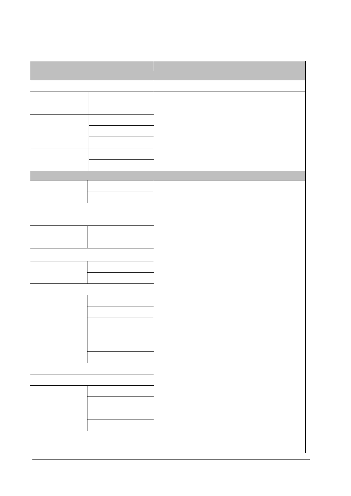
3.1.3 Recommended Frequency
Check/Maintenance Item Frequency
Preventative Maintenance Tests
Visual inspection When first installed or reinstalled.
NIBP tests
Sidestream and
Microstream CO
tests
2
AG tests
Performance Tests
ECG tests
Resp test
SpO2 test
NIBP test
Temp test
IBP tests
C.O. test
Sidestream and
Microstream CO
tests
2
Pressure check
Leakage test
Leakage test
Performance test
Calibration
Performance test
Calibration
Performance test
Calibration
Pressure check
Leakage test
Performance test
Pressure calibration
Leakage test
Performance test
Calibration
Leakage test
1. If the user suspects that the measurement is incorrect.
2. Following any repair or replacement of relevant module.
3. For NIBP module, at least once every two years; for CO2 and AG
modules, once a year.
4. AG leakage test should be performed before AG measurement.
1. If the user suspects that the measurement is incorrect.
2. Following any repair or replacement of relevant module.
3. At least once every two years. For CO
AG and NMT modules, at
2,
least once a year.
4. AG leakage test should be performed before AG measurement.
AG tests
Performance test
Calibration
EEG test
BIS test
Interconnecting function
CCO/SvO2 tests
Output calibration
Performance test
NMT tests
Sensor check
Nurse call relay performance test
Analog output performance test
If the user suspects that the nurse call or analog output does not
function properly.
3-2 BeneVision N22/BeneVision N19 Patient Monitor Service Manual
Page 29

Electrical Safety Tests
Earth impedance
Electrical safety tests
Earth leakage test
Patient leakage current
Patient auxiliary current
Other Tests
Power on test
Recorder check Following any repair or replacement of the recorder.
1. Following any repair or replacement of the power module.
2. When the patient monitor is dropped.
3. At least every two years or as required.
1. When first installed or reinstalled.
2. Following any maintenance or the replacement of any main unit
parts.
Network print test
Device integration check
Function test
Battery check
Performance test
Mounting check
Note: Performance test is not required for the rSO
and the ScvO
needs to be calibrated prior to use.
2
1. When first installed.
2. Whenever the printer is serviced or replaced.
1. When first installed.
2. Following any repair or replacement of the external device.
1. When first installed.
2. Whenever a battery is replaced.
Once every two months or when the battery run time is reduced
significantly.
1. When first installed.
2. At least every two years or as required.
, and ScvO2 modules, because the rSO2, modules perform self tests,
2
3.2 Preventative Maintenance Procedures
3.2.1 Visual Inspection
Inspect the equipment for obvious signs of damage. The test is passed if the equipment has no obvious signs of
damage. Follow these guidelines when inspecting the equipment:
Carefully inspect the case, display screen, buttons, knobs, and handle for obvious signs of damage.
Inspect the SMR and parameter modules for obvious signs of damage.
Inspect the power cord, bracket and module accessories for obvious signs of damage.
Inspect all external connections for loose connectors, bent pins or frayed cables.
Inspect all connectors on the equipment for loose connectors or bent pins.
Make sure that safety labels and data plates on the equipment are clearly legible.
BeneVision N22/BeneVision N19 Patient Monitor Service Manual 3-3
Page 30
3.2.2 NIBP Tests
3.2.2.1 Leakage Test
Tools required:
NIBP cuff for adult patient
NIBP hose
Cylinder
Follow this procedure to perform the test:
1. Set Patient Category to Adult.
2. Connect the NIBP cuff to the NIBP connector on the patient monitor.
3. Wrap the cuff around the rigid cylinder as shown below.
Monit
Hose
NIBP connector
4. Select Main Menu → Maintenance → enter the required password → Module → NIBP → NIBP Leakage
Test. The message NIBP Leakage Test is displayed in the NIBP parameter area.
5. The cuff automatically deflates after 20s, which means NIBP leakage test is completed.
6. If no message is displayed in the NIBP parameter area, it indicates that the system has no leak. If the message
NIBP Airway Leak is displayed, it indicates that the system may have a leak. In this case, verify the connections
and make sure that the NIBP cuff, hose, and connectors are not leaking. Then, perform the test again.
You can also perform a manual leakage test:
1. Perform steps 1-4 in the 1.2.2.2 NIBP Accuracy Test section.
2. Raise the pressure in the rigid vessel to 250 mmHg with the squeeze bulb. Then, wait for 5 seconds until the
measured values become stable.
3. Record the current pressure value and meanwhile count time with a timer. Then, record the pressure value after
counting to 60 seconds.
Cylinder
Cuff
4. Compare the two values and make sure the difference is not greater than 6 mmHg.
3-4 BeneVision N22/BeneVision N19 Patient Monitor Service Manual
Page 31

3.2.2.2 NIBP Accuracy Test
Squeeze bulb
Tools required:
T-shape connector
Tubing
Squeeze bulb
Rigid vessel with 500 ± 25 ml internal volume
Reference manometer (calibrated with accuracy equal to or greater than 1 mmHg)
Follow this procedure to perform the test:
1. Connect the equipment as shown below.
Monitor
Tubing
NIBP connector
2. Before inflation, the reading on the manometer should be zero. If not, open the valve of the squeeze bulb to let
the whole airway open to the atmosphere. Close the valve after the reading turns to zero.
3. Select Main Menu → Maintenance → enter the required password → Module → NIBP → NIBP Accuracy
Test.
4. Check the reading of the manometer and the reading of the patient monitor. Both should be 0 mmHg.
5. Raise the pressure in the rigid vessel to 50 mmHg with the squeeze bulb. Then, wait for 10 seconds until the
measured values become stable.
6. Compare the reading of the manometer with the reading of the patient monitor. The difference should be 3
mmHg or less. If it is greater than 3 mmHg, contact your service personnel.
Manometer
Rigid vessel
7. Raise the pressure in the rigid vessel to 200 mmHg with the squeeze bulb. Then, wait for 10 seconds until the
measured values become stable. Repeat step 6.
NOTE
You can use an NIBP simulator to replace the squeeze bulb and the reference manometer to
perform the test.
You can use an appropriate cylinder and a cuff instead of the rigid vessel.
BeneVision N22/BeneVision N19 Patient Monitor Service Manual 3-5
Page 32

3.2.3 Sidestream and Microstream CO
Leakage Test
1. Plug the module into the module rack.
Tests
2
2. Wait until CO
your finger or a pinched sample line). The sidestream and microstream CO
Sidestream: Plug the sidestream CO
the module warmup is finished and then completely block the gas inlet of the module (you may use a
pneumatic plug or your finger to manually occlude the port). An alarm message CO2 Airway Occluded will
appear on the screen. Block the gas inlet for another 60 seconds. Select Main Menu → Maintenance →
enter the required password → Module → CO2 → Calibration. If the flow rate is less than 10 ml/min and
the alarm message continues, it indicates that the module does not leak. If the alarm message CO2 Airway
Occluded disappears, or the flow rate is greater than or equal to 10 ml/min, it indicates that the module
leaks.
Microstream: After 3 seconds, the alarm message "CO
inlet for another 30 seconds. If the alarm message "CO
module does not leak.
Accuracy Test
Tools required:
For microstream CO
21.0% O2 and balance gas N2 (P/N 0075-00-0033-01) o r a st e e l ga s cylin d er w it h:
2 warmup is finished and then completely block the gas inlet of the module or water trap (by using
2 modules will behave as follows:
module into the module rack of the main unit. Wait one minute until
2
Purging" is displayed on the screen. Block the gas
2
Airway Occluded" is displayed, it indicates that the
2
module and sidestream CO2 module without O2 module, a gas cylinder with 5±0.03% CO2,
2
CO2 concentration 3% - 7 %
a / c ≤ 0 .0 1 (w h e r e a = a b s o lu te g a s c o n c e n t r a t io n a c c u ra c y , c = g a s c o n c e n t r a tio n )
balance gas N2
For sidestream CO
module with O2 module equipped, a steel gas cylinder (P/N 0075-00-0048-01) with 6% CO2, 4%
2
Desflurane, 45% N2O, and 45% O2,
T-shape connector
Tubing
Flowmeter
1. Plug the module into the module rack.
2. Wait until the CO2 module warmup is finished. Check the airway for leak and perform a leakage test as well to
make sure that the airway has no leak.
3. Select Main Menu → Maintenance → enter the required password → Module → CO2.
4. Connect the test system as follows:
3-6 BeneVision N22/BeneVision N19 Patient Monitor Service Manual
Page 33

Flowmeter
Tubing
Relief valve
T-shape connector
Monitor
Gas cylinder
5. Open the relief valve, and adjust it until the flowmeter has a stable reading between
10 ml/min and 50 ml/min.
6. Verify that the real-time CO
value is within 6±0.2% in the CO2 Maintenance menu (for microstream CO2, the
2
value is 45±2 mmHg).
7. Replace the cylinder to the steel gas cylinder with >40% O
module with O
±3% (80%≤O
module equipped) and verify that the real-time O2 value error is within ±2% (when O2≤80%) or
2
≤100%).
2
Calibration
Tools required:
For microstream CO
module and sidestream CO2 module without O2 module, a gas cylinder with 5±0.03% CO2,
2
21.0% O2 and balance gas N2 (P/N 0075-00-0033-01) or a st e e l ga s cylin d e r wit h:
CO2 concentration 3% - 7 %
a / c ≤ 0 .0 1 (w h e r e a = a b s o lu te g a s c o n c e n t r a t io n a c c u ra c y , c = g a s c o n c e n t r a tio n )
balance gas N2
For sidestream CO
module with O2 module equipped, a steel gas cylinder (P/N 0075-00-0048-01) with 6% CO2, 4%
2
Desflurane, 45% N2O, and 45% O2,
T-shape connector
and balance gas N2(applicable to sidestream CO2
2
Tubing
Flowmeter
1. Make sure that the sidestream or microstream CO
module has been warmed up or started up.
2
2. Check the airway for leaks and perform a leakage test as well to make sure that the airway has no leakage.
3. Select Main Menu → Maintenance → enter the required password → Module → CO2.
4. In the CO2 Maintenance menu, select Zero.
5. After the zero calibration is finished successfully, connect the equipment as follows:
BeneVision N22/BeneVision N19 Patient Monitor Service Manual 3-7
Page 34

Flowmeter
Tubing
Relief valve
Monitor
T-shape connector
Gas cylinder
6. Open the relief valve, and adjust it until the flowmeter has a stable reading between
10 ml/min and 50 ml/min.
7. In the Calibrate CO2 menu, select 6% (the CO
concentration) for CO2 calibration. The measured CO2
2
concentration is displayed.
8. After the measured CO
concentration becomes stable, select Calibrate CO2 to calibrate the CO2 module.
2
9. Replace the cylinder to the steel gas cylinder with >40% O2 and balance gas N2 (applicable to sidestream CO2
module with O2 module equipped) and calibrate O2.
If the calibration is finished successfully, the message Calibration Completed! is displayed in the Calibrate CO2 menu. If
the calibration failed, the message Calibration Failed! is displayed. In this case, check whether the operations are
correct and perform another calibration. If the calibration fails several times, return the module to Mindray for repair.
3.2.4 AG Tests
Leakage Test
1. Plug the AG module into the module rack.
2. Wait until the AG module warmup is finished and then completely block the gas inlet of the AG module (you may
use a pneumatic plug or your finger to manually occlude the port). An alarm message AG Airway Occluded will
appear on the screen.
3. Block the gas inlet for another 60 seconds. Select Main Menu → Maintenance → enter the required password
→ Module → AG → Calibration. Check that the flow rate is less than 10 ml/min. If the alarm message
continues, it indicates that the module does not leak.
If the alarm message disappears, or the flow rate is greater than or equal to 10 ml/min, it indicates that the module
leaks.
Accuracy Test
Tools required:
Gas cylinder with a certain standard gas (such as 6±0.05% CO2, Bal N
) or standard gas mixture. Gas
2
concentration should meet the following requirements: AA > 1.5%, CO2 > 1.5%, N2O > 40%, O2 > 40%, of which
3-8 BeneVision N22/BeneVision N19 Patient Monitor Service Manual
Page 35

AA represents an anesthetic agent. Precision requirement: a/c ≤ 0.01 (a is the gas absolute concentration
accuracy; c is the gas concentration)
T-shape connector
Tubing
Flowmeter
1. Plug the AG module into the module rack.
2. Wait at least 10 min and then perform a leakage test to make sure that the airway has no leakage.
3. Connect the test system as follows:
Flowmeter
Tubing
Relief valve
T-shape connector
Monitor
Gas cylinder
4. Open the relief valve, and adjust it until the flowmeter has a stable reading between 10 ml/min and 50 ml/min.
5. Verify that the concentration of each composition meets the specification stated in the Operator's Manual.
Calibration
Tools required:
A supply of medical grade 100% O2 and an anesthetic calibration gas (4% Desflurane, 6% CO2, 45% N2O, Bal O2,
P/N: 0075-00-0048-01 and flow regulator P/N: 0119-00-0235). Gas concentration should meet the following
requirements:
AA ≥ 1.5%, CO2 ≥ 1.5%, N2O ≥ 40%, O2 ≥ 40%, of which AA represents an anesthetic agent.
a/c ≤ 0.01 (a is the gas absolute concentration accuracy; c is the gas concentration)
T-shape connector
Tubing
Follow this procedure to perform a calibration:
1. Select Main Menu → Maintenance → enter the required password → Module → AG.
2. Check the airway and make sure that there are no occlusions or leaks.
BeneVision N22/BeneVision N19 Patient Monitor Service Manual 3-9
Page 36

Vent the sampling tubing to the air and check if the Current Flow Rate and Set Flow Rate are approximately
the same. If the deviation is great, it indicates that there is an occlusion in the tubing. Check the tubing for
an occlusion.
Perform a leakage test to make sure that the airway has no leakage.
3. Connect the test system as follows:
4. Open the relief valve and vent a certain standard gas or gas mixture. Adjust the relief valve until the flowmeter
has a stable reading between 10 ml/min and 50 ml/min.
Flowmeter
Tubing
Relief valve
T shape connector
Monitor
Gas cylinder
5. In the Calibrate AG menu, the concentration and flowrate of each measured gas are displayed.
If the difference between the measured gas concentration and the actual one is within tolerance, a
calibration is not needed.
If the difference is not within tolerance, a calibration should be performed. Select Calibrate.
6. Enter the vented gas concentration. If you use only one gas for calibration, set other gases' concentration to 0. If
the calibration is performed for all gases, the gas with an entered calibration value of 0 is not
calibrated.
7. Select Calibrate to start a calibration.
8. If the calibration is finished successfully, the message Calibration Completed! is displayed. If the calibration failed,
the message Calibration Failed! is displayed. In this case, perform another calibration. If the calibration fails
several times, return the module to Mindray for repair.
CAUTION
Calibrate the O
module, if it has been transported for long distance.
2
3-10 BeneVision N22/BeneVision N19 Patient Monitor Service Manual
Page 37

3.3 Power On Test
This test is to verify that the patient monitor can power up correctly. The test is passed if the patient monitor starts up
by following this procedure:
1. Connect the patient monitor to the AC mains. The AC mains LED and battery LED light up.
2. Press the power on/off switch to switch on the patient monitor. The system sounds a beep indicating the self test
on alarm sounds is passed. The alarm lamps light red, yellow and cyan respectively, and then go off, indicating
the self test on alarm sound is passed.
3. The patient monitor enters the main screen and start-up is finished.
3.4 Module Performance Tests
3.4.1 ECG Tests
ECG Performance Test
Tools required:
Medsim300B patient simulator or other equivalent simulator
1. Connect the patient simulator with the ECG module using an ECG cable.
2. Set the patient simulator as follows: ECG sinus rhythm, HR = 60 bpm with the amplitude as 1 mV.
3. Verify that the ECG waves are displayed correctly without noise and the displayed HR value is within 60±1 bpm.
4. Disconnect each of the leads in turn and observe the corresponding lead off message displayed on the screen.
5. Set the output of the simulator to deliver a paced signal and set Paced to Yes on the monitor. Check the pace
pulse marks on the monitor screen.
ECG Verification
Tools required: vernier caliper
1. Select the ECG parameter window or waveform area →Filter→Diagnostic.
2. Select Main Menu →Maintenance → enter the required password → Module..
3. Select
4. Compare the amplitude of the square wave with that of the scale. The difference should be with 5%.
5. After completing the calibration, select Stop Calibration.
If necessary, you can print out the square wave and wave scale through the recorder and then measure the difference.
Calibration. A square wave appears on the screen and the message "ECG Calibrating" is displayed.
BeneVision N22/BeneVision N19 Patient Monitor Service Manual 3-11
Page 38

3.4.2 Resp Test
Tools required:
Medsim300B patient simulator or other equivalent simulator
1. Connect the patient simulator to the module using a non ESU-proof cable and set lead II as the respiration lead.
2. Configure the simulator as follows: lead II as the respiration lead, base impedance line as 500 Ω; delta impedance
as 1 Ω, respiration rate as 20 rpm.
3. Verify that the Resp wave is displayed without any distortion and the displayed Resp value is within 20±1 rpm.
3.4.3 SpO
Tools required:
None.
1. Connect SpO2 sensor to the SpO2 connector of the monitor. Set Patient Category to Adult and PR Source to SpO2
Test
2
on the monitor.
2. Apply the SpO
sensor to the ring finger of a healthy person.
2
3. Check the Pleth wave and PR reading on the screen and make sure that the displayed SpO2 is within 95%
and100%.
4. Remove the SpO
sensor from your finger and make sure that an alarm of SpO2 Sensor Off is triggered.
2
Measurement accuracy verification:
The SpO
accuracy of the MPM module has been verified in human experiments by comparing with arterial blood
2
sample reference measured with a CO-oximeter. Pulse oximeter measurements are statistically distributed and about
two-thirds of the measurements are expected to come within the specified accuracy range compared to CO-oximeter
measurements.
NOTE
A simulator cannot be used to assess the accuracy of a pulse oximeter monitor or a SpO
sensor. Instead, it can only verify that whether the monitor is functional. The accuracy of a
pulse oximeter monitor or a SpO2 sensor needs to be verified by clinical data.
2
3.4.4 NIBP Tests
See section 3.2.2NIBP Tests.
3-12 BeneVision N22/BeneVision N19 Patient Monitor Service Manual
Page 39

3.4.5 Temp Test
Tools required:
Resistance box (with accuracy above 0.1 Ω)
1. Connect the two pins of any Temp connector of a module to the two ends of the resistance box using two wires.
2. Set the resistance box to 1354.9 Ω (corresponding temperature is 37ºC).
3. Verify each Temp channel of the monitor and make sure that the displayed value is within 37±0.1ºC.
4. Repeat steps 1 to 3 to verify each Temp channel of the monitor.
3.4.6 IBP Tests
Performance Test
Tools required:
Patient simulator Medsim300B, MPS450, or other equivalent equipment
Dedicated IBP adapter cable (P/N 00-002199-00 for 300B, P/N 00-002198-00 for MPS450)
1. Connect the patient simulator to the monitor's IBP connector.
2. Set the patient simulator output to the IBP channel to 0 mmHg.
3. Press the Zero key on the module to make a zero calibration.
4. Set static pressure to 200 mmHg on the patient simulator.
5. The displayed value should be within 200±2 mmHg.
6. If the error is beyond ±2 mmHg, calibrate the IBP module. If the IBP module was calibrated with a dedicated
reusable IBP sensor, check the calibration together with this IBP sensor.
7. Make the patient simulator outputs 120/80 mmHg ART signals and 120/0 mmHg LV signals respectively to each
IBP channel and check that the IBP wave is displayed correctly.
8. Repeat the preceding steps to test all IBP channels.
Pressure Calibration
Method 1:
Tools required:
Medsim300B patient simulator, MPS450, or other equivalent equipment
Dedicated IBP adapter cable (300B, P/N 00-002199-00) (use P/N 00-002198-00, if the simulator is MPS450)
1. Connect the patient simulator to the monitor's IBP connector.
2. Set the patient simulator to 0 pressure for the desired IBP channel.
3. Press the Zero key from the IBP menu.
4. Set static pressure to 200 mmHg on the patient simulator.
5. Select Main Menu → Maintenance → enter the required password → Module → IBP.
6. Set the calibration value to 200 mmHg.
BeneVision N22/BeneVision N19 Patient Monitor Service Manual 3-13
Page 40

7. Select the Calibrate button next to the desired IBP channel to start a calibration.
8. If the calibration is completed successfully, the message Calibration Completed! will be displayed. Otherwise, a
corresponding message will be displayed.
Method 2:
Tools required:
Standard sphygmomanometer
Squeeze bulb
Tubing
T-shape connector
1. Connect the 3-way stopcock, the sphygmomanometer and the squeeze bulb through a T-shape connector, as
shown below.
2. Zero the transducer, and then open the stopcock to the sphygmomanometer.
Pressure transducer
3-way stopcock
Pressure adapter cable
T-shape connector
Sphygmomanometer
3. Select Main Menu→ Maintenance → enter the required password → Module → IBP. In the displayed
interface, set the target calibration value of the target channel. Value range: 80 to 300 mmHg.
4. Inflate using the squeeze bulb until the reading of sphygmomanometer approximates the preset calibration
value.
5. Adjust the calibration value in the IBP Maintenance menu until it is equal to the reading of sphygmomanometer
6. Select the Calibrate button next to the desired IBP channel to start a calibration.
If the calibration is completed successfully, the message Calibration Completed! will be displayed. Otherwise, a
corresponding message will be displayed.
IBP
module
3-14 BeneVision N22/BeneVision N19 Patient Monitor Service Manual
Page 41

3.4.7 C.O. Test
Tools required:
Medsim300B patient simulator or other equivalent simulator
C.O. adapter box (for 300B)
1. Connect the patient simulator to the C.O. module using a C.O. main cable.
2. Set the blood temperature (BT) to 37ºC on the patient simulator and check the temperature value is 37±0.1ºC.
3. Switch off Auto TI and adjust TI (IT) to 24ºC. Select C.O. Measure to enter the C.O. measurement window and set
Comp. Const. to 0.595.
4. Set the injectate temperature to 24ºC and the C.O. to 5 L/min on the C.O. simulator. Select Start in the C.O.
measurement window to start C.O. measurements, and press the run key on the simulator after 3-10 seconds.
6. Verify that the C.O. value is 5±0.25 L/min.
3.4.8 Sidestream and Microstream CO
See section 3.2.3Sidestream and Microstream CO2 Tests.
Tests
2
3.4.9 AG Tests
See section 3.2.4AG Tests.
3.4.10 EEG Test
You can choose either of the following methods to perform the test:
Method 1:
Tools required:
ECG simulator with Sine wave output function.
1. Connect pins of EEG lead wires to an ECG simulator.
Set the ECG simulator to output Sine wave and frequency to between 0.5 and 30Hz. The range is 2mV. The GND pin of
EEG module connects to RL of ECG simulator. The A+ pin of EEG module connects to LA of ECG simulator. The other
pins of EEG lead wires connect to any ECG lead as you wish.
2. Open the EEG setting menu on monitor, Set the Scale of EEG to be 2000uV. Then you can find a Sine wave on
screen of Patient Monitor.
Method 2:
Tools required:
None.
Connect all the pins of EEG lead wire together, for example, you can connect them to some metal materials. Then
check the EEG module resistance test, if all the leads are green then pass.
BeneVision N22/BeneVision N19 Patient Monitor Service Manual 3-15
Page 42

Method 3:
Tools required:
Resistance box
Multimeter
1. Connect the EEG module/cable to the EEG simulator and the monitor.
2. Set Montage Type: Bipolar Mode.
3. Adjust the resistance box to 1 kΩ, verify the resistance value displayed on the monitor is 1kΩ.
4. Test the lead type of the monitor to B+, C+ and D+ respectively instead of lead A+.
5. Set Montage Type: Monopolar Mode , then repeat the step 3~4.
3-16 BeneVision N22/BeneVision N19 Patient Monitor Service Manual
Page 43

3.4.11 BIS Test
You can choose either of the following methods to perform the test:
Method 1:
Tools required:
None.
1. Connect the BIS sensor to a healthy, wide-awake adult as directed in the Operator's Manual.
2. Check the EEG wave and BIS numerics displayed on the screen and make sure the BIS value is within 80 and 100.
Method 2:
Tools required:
BIS simulator (Covidien PN: 186-0137)
1. Connect the BIS sensor with the BIS simulator. Select BIS area parameter or waveform to access BIS Setup. Then,
select Sensor Check to perform a cyclic impedance check.
2. After the cyclic impedance check is finished, check that the result for each electrode is passed.
Method 3:
Tools:
Signal generator, (Maker: NF, Model:WF1946B)
Covidien Signal simulator (Covidien PN:189-0137)
1. Insert the BIS module to the monitor, connect the BIS module/cable to the Covidien Signal simulator, signal
generator.
2. Adjust the signal generator to produce a 90Hz, 35.4mV(RMS) sine signal to the Convidien Signal simulator.
3. Set the time length of the review window to the shortest.
4. Verify the EMG value range from 65 to 75, and SQI value should be 100 displayed on Graphic Trends.
3.4.12 CCO/SvO
Tests
2
Interconnecting Function
Tools required:
None.
1. Connect and set the patient monitor and Vigilance monitor per the procedures in the Operator's Manual.
2. Set the Vigilance monitor to Demo mode. Start the CCO and SvO2 tests in Demo mode.
3. Verify that the CCO/SvO2 numerics displayed on the patient monitor and Vigilance monitor are consistent.
BeneVision N22/BeneVision N19 Patient Monitor Service Manual 3-17
Page 44

Output Performance
Tools required:
Multimeter
1. Connect the signal output end of the connecting cables of the CCO/SvO
module to the oscilloscope.
2
2. Select CCO Setup → Signal Output Setup and then select Simulated High Value from the pop-up menu. Check
that the amplitude of electrical level at the signal output port of ECG, MAP, CVP and SpO
are 5±0.015 V, 5±0.25 V,
2
5±0.25 V and 10±0.5 V respectively.
3.4.13 NMT Tests
Performance Test
Method 1:
Tools required:
Resistance box
Multimeter
1. Set the resistance value to 1kOhm. Connect the stimulation electrodes to the two wiring terminals.
2. Set the multimeter to operate in DC mode. Connect the multimeter sensors to the NMT stimulation electrodes,
making sure that the sensor and electrode connected have the same polarity.
3. Insert the NMT module into the module rack of the monitor. Select the NMT parameter area of the monitor to
access the NMT Setup menu. Set the Stimulation Current to Supra(60mA). Set the Pulse Width to 300μs. Perform
a PTC measurement.
4. Check the voltage change detected by the multimeter and verify normal output of NMT stimulation.
Method 2:
Tools required:
Resistance box (0~9999.9 Ω)
Oscilloscope (Agilent DS0-X3014A)
1. Set resistance box to 1kOhm, connect stimulation electrodes to the resistance box.
2. Insert the NMT module to monitor. Set [Stimulation current] to [Supra (35mA)], [Pulse width] to 200μs. Select [ST
Mode] in NMT setup menu to start a ST measure.
3. Measure the voltage wave of the resistance box by oscilloscope, verify the pulse width is range from 180 to 220us,
and calculate the Stimulation Current according stimulation voltage should be range from 33 to 37mA.
3-18 BeneVision N22/BeneVision N19 Patient Monitor Service Manual
Page 45

Sensor Check
Tools required: None.
1. Connect the patient monitor, NMT module, and NMT accessories.
2. Select Main Menu → Maintenance → enter the required password → Module → NMT.
3. Follow the on-screen instructions to check the NMT sensor.
If sensor check completes successfully, the message Test passed. The function of NMT sensor is OK is displayed,
indicating a functional sensor. If the check fails, check whether the sensor is placed correctly as instructed, and
perform the sensor check again.
NOTE
Stop NMT measurement or calibration before starting NMT sensor check.
Avoid forcefully striking the sensor.
3.5 Nurse Call Relay Performance Test
Tools required: Multimeter
1. Connect the nurse call cable to the Nurse Call Connector of the patient monitor.
2. Enter Demo mode. Then, select Main Menu → Maintenance >> → enter the required password → Alarm to
access the Nurse Call setup menu.
3. In Nurse Call menu, select all options of Alarm Priority and Alarm Type. and set Contact Type to Normally Open.
4. In Nurse Call menu, set Signal Type to Pulse. Cause the monitor to generate an alarm and verify the output are
pulses of 1s width and the relay contacts are closed (can be measured with a multimeter) when there is an alarm.
5. In Nurse Call menu, set Signal Type to Continuous. Cause the monitor to generate an alarm and verify the output
is continuous high level and the relay contacts are closed (can be measured with a multimeter) when there is an
alarm.
3.6 Analog Output Performance Test
Tools required:
Patient simulator
Oscilloscope
1. Connect the patient simulator to the monitor using an ECG or IBP cable and connect the oscilloscope to the
Auxiliary Output Connector of the MPM module of the patient monitor.
2. Verify that the waves displayed on the oscilloscope are identical with those displayed on the monitor.
BeneVision N22/BeneVision N19 Patient Monitor Service Manual 3-19
Page 46

3.7 Electrical Safety Tests
WARNING
Electrical safety tests are a proven means of detecting abnormalities that, if undetected, could prove
dangerous to either the patient or the operator.
All tests can be performed using commercially available safety analyzer test equipment. Maintenance
personnel shall ensure the adaptability, functional completeness and safety of these pieces of test
equipment, and be familiar with their usage.
Electrical safety tests shall comply with the following standards: IEC 60601-1 and ANSI/AAMI ES60601-1.
In case of other stipulations in local laws and regulations, implement electrical safety tests by following
relevant stipulations.
All devices driven by AC power and connected to medical instruments in patient zones must comply with
the IEC 60601-1 standard. And electrical safety tests on these devices must be implemented in accordance
with the test interval of the patient monitor.
Use certified safety analyzer (for example, UL, CSA or AMAI) as instructed to perform relevant tests.
NOTE
Electrical safety check shall be performed after repair or routine maintenance. Ensure that all cover boards,
panels and screws are correctly installed before implementing electrical safety tests.
Electrical safety tests are used to timely detect potential electrical safety risks that might cause damage to
patients, operators or maintenance personnel. Electrical safety tests must be carried out under normal
environmental conditions (that is, normal temperature, humidity and barometric pressure).
See Appendix A Electrical Safety Inspection for electrical safety tests.
3.8 Recorder Check
Tools required:
None.
1. Print ECG waveforms. The recorder should print correctly and the printout should be clear.
2. Set the recorder to some problems such as out of paper, etc. the patient monitor should give corresponding
prompt messages. After the problem is removed, the recorder should be able to work correctly.
3. Switch automatic alarm recording for each parameter ON and then set each parameter's limit outside set alarm
limits. Corresponding alarm recordings should be triggered when parameter alarms occur.
3-20 BeneVision N22/BeneVision N19 Patient Monitor Service Manual
Page 47

3.9 Network Print Test
NOTE
HP LaserJet Pro M202dw laser printer is recommended for BeneVision patient monitor series
3.9.1 Device Connection and Setup
1 Connect the patient monitor and network printer to a network switch using common network cables as follows:
BeneVisi
on
Network cable
2 Select Main Menu → Maintenance → enter the required password →Network Setup and set the IP address of
the patient monitor in the same network segment with that of the network printer. (See the instructions for use
accompanying the printer)
3 Select Main Menu → Maintenance → enter the required password → Print and set the IP address of the
printer to the actual IP address, and set the paper size to the actual size.
4 Set the print resolution to 300dpi or 600dpi as required.
5 Click Print Test Page to check whether the output of the printer's test page is normal. If not, recheck the
connection and configuration of the printer.
Network cable
Switch
Network
printer
3.10 Battery Check
Tools required:
None.
Function Test
1. Verify that the patient monitor works properly when running on AC power.
2. Remove the AC power cord and verify that the patient monitor still works properly.
Performance Test
Perform the test procedure in the Battery section in the Operator's Manual and verify the operating time of the
battery meets the product specification.
BeneVision N22/BeneVision N19 Patient Monitor Service Manual 3-21
Page 48

3.11 Mounting Check
Tools required: None.
3.11.1 Safety check
Check the mounting of Patient Monitor is safe.
3.11.2 Overall Test and Check of Installed System
Implement installation test:
The following tests and checks need to be performed after a patient monitor is installed, or reinstalled after being
disassembled and repaired:
The following tests and checks need to be performed after a patient monitor is installed, or reinstalled after being
disassembled and repaired:
Check that the screws fastening the bracket and guide rail are not loose.
Check that the four installation screws on the rear side of the main unit are not loose.
Check that the main unit and the VESA metal plate are closely attached.
Check that the connection between stand and bracket is not loose.
Check that the screws at the installation support leg for fixing fast lock are not loose.
Check that the fast lock or lock plug at the rear side of the module rack is not loose.
Check that the modules can be normally and securely inserted into the module rack.
Check that the trim strip is properly installed after the display is disassembled and repaired.
Check that the display handle is not loose.
Check that the length of display wire allows for flexible turn of the display and angle adjustment of the monitor.
Check that the monitor can be placed at any angle as required.
Check that the VHM bracket can place the monitor at any height as required.
Check that the screws on the rotation part of the display are securely installed, and that the damping force is
properly set.
3-22 BeneVision N22/BeneVision N19 Patient Monitor Service Manual
Page 49

4 Troubleshooting
4.1 Introduction
This chapter lists the problems that may occur during use of the monitor and recommended measures. Refer to the
table in this chapter to check the monitor, confirm and fix these problems. For more information about the
troubleshooting, please contact Mindray service.
4.2 Part Replacement
For the monitor, the PCB, main parts and components can be replaced. For the LCD or touch screen fault, only the
front case assembly can be replaced. Once the faulty PCB is confirmed, replace the PCB according to the operation
guide in Chapter 6 Disassembly and Repair. Then, confirm that the monitor can operate normally and has passed all
the performance tests. For the information about replaceable parts, refer to Chapter 7 Parts.
4.3 Check before Powering on the Monitor
After the AC power supply is connected, check whether the AC indicator is turned on. If not, confirm whether the AC
cable is connected to the socket and monitor reliably. If both the AC external power supply and power cord are
connected normally, but the AC indicator is off, the AC-DC power module or main control board of the main unit may
be damaged. Now, you need to run the monitor on battery powered on. If the monitor cannot be powered on, the
main control board may be damaged or the internal board is abnormal, resulting in power supply protection. If the
monitor can be run on battery power, the AC-DC power module is damaged.
In addition, check the appearance for damages before powering on. Particularly, when the touch screen of the screen
assembly is damaged, stop using the monitor immediately.
4.4 Software Version Check
Some troubleshooting tasks may involve software version compatibility. For information about the configuration and
software version of your patient monitor, contact Mindray service. To check the software version, do as follows:
Select Main Menu quick key, from the System column, select Version. You can check the version information of
the system software.
Select Main Menu quick key, from the System column, select Maintenance >> → enter required password →
select Version. In the displayed menu, you can check the version information of the system software and
modules.
BeneVision N22/BeneVision N19 Patient Monitor Service Manual 4-1
Page 50

4.5 Technical Alarm Check
Remove AC and connect
after 5s, and press the
power-on button
The power LED of the module
rack is ON or the alarm LED of the
front housing is blinking?
Check the
power on
signal cable
of the front
housing
Y
N
Remove AC, and press the
power on/off button for 15s
to restart the system if the
battery is available
Front housing
display
interface board
defective
AC LED is ON?
Power-on button
LED is ON?
Check ACDC, and
the ACDC may be
damaged.
N
N
Battery is provided?
Y
N
The coaxial
cable of the
interface is
damaged
Arranged according to the possible order
Screen line,
screen and
backlight line
defective
Mother
control board
defective
Y
The coaxial
cable of the
display
interface is
damaged
DCDC
board
failure
Before troubleshooting the patient monitor, check for technical alarm message. If an alarm message is presented,
eliminate the technical alarm first. For detailed information on technical alarm messages, possible causes and
countermeasures, refer to N series Operator’s Manual (P/N: 046-011259-00).
4.6 Blank Screen upon Startup
4-2 BeneVision N22/BeneVision N19 Patient Monitor Service Manual
Page 51

4.7 Troubleshooting Guide
4.7.1 Power On/Off Failures
Fault Symptom Possible Cause Countermeasure
Power on failure
AC mains not connected or
insufficient battery power or
battery damaged
Cable defective or improperly
connected
Verify the AC mains is properly connected.
Verify the battery capacity is sufficient and
the batter is not damaged.
Verify the cables connecting the power switch and
the LED board to the front housing interface board,
the cable connecting the front housing interface
board to the coaxial cable of main control, and the
cable connecting the power module to the DCDC
board are properly connected.
Note: The process for the coaxial cable connecting
the front housing interface board and the main
control is complicated; therefore, protective
measures must be adopted during installation to
prevent the coaxial cable from being damaged.
2. Verify the cables and connectors are not damaged.
Power switch & LED board defective Replace the power switch & LED board.
Power module defective Replace the power module.
Motherboard failure Replace the motherboard.
BeneVision N22/BeneVision N19 Patient Monitor Service Manual 4-3
Page 52

4.7.2 Display Failures
Fault Symptom Possible Cause Countermeasure
Blank screen, but the
patient monitor still
operates normally
Secondary screen
does not function
Cable defective or improperly connected 1. Verify the cable connecting the power switch and
the LED board to the front housing interface board,
the cable connecting the front housing interface
board to the coaxial cable of main control, and the
cable connecting the power module to the DCDC
board are properly connected.
2. Verify the connecting cables and connectors are
not damaged.
LCD defective Replace the LCD.
Cable defective or improperly connected 1. Verify the cable connecting the display DP1
connector and the patient monitor is properly
connected.
2. Verify the cables and connectors are not
damaged.
DP cable of the secondary screen is not
inserted into the connector of the main unit
when the system is powered on
Switch of the secondary screen is in the
power off state
Power off the main unit. Connect the DP cable of the
secondary screen to the main unit. Then restart the
main unit.
Press the power-on button of the secondary screen
for 5s to start the secondary screen.
Touchscreen does not
respond
Touchscreen disabled
Cable defective or improperly connected 1. Verify the cables connecting the touchscreen to
Touchscreen control board defective Replace the touchscreen control board.
Front housing interface board failure
Check if there is a symbol shown above the
Main Menu QuickKey. If yes, press Main Menu for
more than 3s to enable the touchscreen.
the touchscreen control board, the cable connecting
the touchscreen control board to the front housing
interface board, and the cable connecting the front
housing interface board to the main board are
properly connected.
2. Verify the cables and connectors are properly
connected
Replace the front housing interface board.
4-4 BeneVision N22/BeneVision N19 Patient Monitor Service Manual
Page 53

4.7.3 Module Rack Failures
Failure Description Possible Cause Troubleshooting
The cable connecting SMR and the main unit of the
monitor is not connected properly or already
External cable defective or
poorly connected
Defective parameter
module
damaged. Verify the connecting cables and
connectors are not damaged.
Verify that contact screws on SMR or module are
tightly fastened and well connected.
Replace the malfunctioning parameter module with a
known good module. If the patient monitor identifies
the replacement module and can start measurement, it
indicates that the original module is faulty.
SMR cannot identify
parameter modules
Wrong communication
board software version
Upgrade the module and/or the SMR software to a
compatible level.
Check whether the SMR interface output voltage of
the main unit is 12 V. If it is abnormal, the internal
SMR power supply
abnormal
module rack COM board or main control board fails.
Check whether the contact screw output voltage of
the external module rack is 12 V. If it is abnormal,
the communication module on the SMR fails.
8-slot Module rack
communication board
defective
DCDC board failure Replace the DCDC board.
Replace 8-slot the module rack communication board.
BeneVision N22/BeneVision N19 Patient Monitor Service Manual 4-5
Page 54

4.7.4 Alarm Failures
Fault Symptom Possible Cause Countermeasure
Alarm LED off or cannot be
turned off while the audible
alarm is sounding
No audible alarm sounds
emitted while the alarm LED
is normal
Cable defective or improperly
connected
Alarm LED board failure Replace the alarm LED board.
Front housing interface board failure Replace the front housing interface board.
Main board failure Replace the main board.
Audible alarm disabled
Cable defective or improperly
connected
Speaker failure Replace the speaker.
1. Verify the cable connecting the alarm LED board to
the front housing interface board, and the cable
connecting the front housing interface board to the
main board are properly connected.
2. Verify the cables and connectors are not damaged.
Select the Main Menu quick key, from the System
column, select Maintenance → enter required
password → select Alarm, set Minimum Alarm
Volume to a proper value. Select the Main Menu
quick key, from the Alarm column, select Setup,
adjust the alarm volume to a proper value.
1. Verify the cable connecting the speaker to the
main board is properly connected.
2. Verify the cables and connectors are not damaged.
Main board failure Replace the main board.
4-6 BeneVision N22/BeneVision N19 Patient Monitor Service Manual
Page 55

4.7.5 Output Interface Failures
Fault Symptom Possible Cause Countermeasure
No output for the nurse call DCDC interface board cable loose 1. Verify the cable connecting the DCDC interface
board to the main board is properly connected.
2. Verify the cables and connectors are not
damaged.
DCDC interface board damaged Replace the DCDC interface board.
Main board failure Replace the main board.
USB Device Unusable
USB enumeration failure Restart the system.
Cable defective or improperly
connected
USB Hub board failure Replace the USB Hub board.
Main board failure Replace the main board.
1. Verify the cable connecting the USB Hub board to
the main board is properly connected.
2. Verify the cables and connectors are not
damaged.
4.7.6 Power Supply Failures
Fault Symptom Possible Cause Countermeasure
Battery cannot supply
power
Battery damaged Replace the battery.
Cable defective or improperly
connected
DCDC interface board damaged Replace the DCDC interface board.
1. Verify the cable connecting the battery interface
board to the power module is correctly connected.
2. Verify the cables and connectors are not
damaged.
Battery cannot be recharged Battery damaged Replace the battery and charge fully. If this is
successful, the original battery is faulty.
Cable defective or improperly
connected
DCDC interface board damaged Replace the DCDC interface board.
No +3.3 V output
No +5.0 V output
No +12 V output
BeneVision N22/BeneVision N19 Patient Monitor Service Manual 4-7
1. Power supply protected
2. DCDC interface board damaged
1. Verify the cable connecting the battery interface
board to the DCDC interface board is correctly
connected.
2. Verify the cables and connectors are not
damaged.
1. Turn off the patient monitor then restart it.
2. If the problem persists, disconnect the AC mains
for 5s and reconnect it, and then restart the patient
monitor.
3. If the problem persists, replace the DCDC interface
board.
Page 56

NOTE
When the power module fails, it may cause damage to other components, e.g. the monitor suddenly fails
during start-up, due to supply protection. In this case, troubleshoot the power module by following the
procedure described in the table above.
Components of the main unit, SMR and parameter modules are powered by the power module. In the event
that a component malfunctions, verify the operating voltage is correct. Refer to Chapter 2 Theory of
Operation for the operating voltage and measurement points for each component.
4.7.7 Network Related Problems
Fault Symptom Possible Cause Countermeasure
Frequent dropouts or
network disconnects
The patient monitor is
connected to a network but
cannot view other patients
in the View Others mode
Improper network cable connection Check for network cable connection and length
(should not exceed 50 m).
Incorrect IP configuration Check for IP conflict in the network and reset the IP
address.
Improper network cable connection Check for network cable connection and length
(should not exceed 50 m).
Too many simultaneous requests for
viewing the patient monitor
Incorrect IP configuration Check for IP conflict in the network and reset the IP
Incorrect network settings Verify the wireless network settings are correct.
Antenna not installed properly Verify the antenna for the wireless network card is
Wireless module damaged Replace the wireless module.
Main control board failure Replace the main control board.
Antenna not installed properly Verify the antenna for the MPAN module is installed
One monitor could only be observed by eight
monitors simultaneously, and the observing
requests not within the range would not be handled.
address.
connected to the wireless module reliably.
properly.
MPAN module damaged Replace the MPAN module.
Satellite module rack (SMR) COM
board defective
Wrong software version for the
MPAN module
4-8 BeneVision N22/BeneVision N19 Patient Monitor Service Manual
Replace the SMR COM board.
Upgrade the MPAN module software.
Page 57

4.7.8 Device Integration Failures
Failure Description Possible Cause Troubleshooting
Replace the ID adapter.
The ID adapter is not compatible
Upgrade the ID of the ID adapter in
"Factory Maintenance" menu.
Replace the serial port adapter cable.
The "Devices Integrated"
window displays nothing
after connection
with the external device
The serial port adapter cable not
compatible with the external device
Wrong software version or wrong
protocol version of the external
device
Generate the alarm:
"BeneLink Comm Stop"
The patient monitor has
no response when loading
the ID adapter
The BeneLink module application
software is corrupted
The BeneLink module application
software is corrupted
BeneLink module damaged Replace the module.
Verify the protocol version and software version
are supported by the ID adapter.
Upgrade or update the software application of
the BeneLink module with the network
upgrading tool.
Upgrade or update the software application of
the BeneLink module with the network
upgrading tool.
BeneVision N22/BeneVision N19 Patient Monitor Service Manual 4-9
Page 58

FOR YOUR NOTES
4-10 BeneVision N22/BeneVision N19 Patient Monitor Service Manual
Page 59

5 Hardware Configuration Options
5.1 Overview
This monitor supports optional monitoring parameter function modules, optional functional assemblies, and network
upgrade of software.
NOTE
For function upgrade involving disassembly of the monitor, eliminate static electricity before
the disassembly. When removing some parts with the electrostatic sensitive mark, wear
protective devices such as electrostatic ring or anti-electrostatic gloves, lest the parts would be
damaged.
Properly connect and route the cables and wires when reassembling the equipment to avoid
pinched hoses and electrical short circuits.
Use specified screws to reassemble the equipment. If the incorrect screws are forcefully
tightened, the equipment may be damaged and the screws or part may fall off during use,
causing unpredictable equipment damage or human injury.
Be sure to follow the correct sequence when disassembling the monitor.
Before removing assemblies, make sure that all the connection lines have been unplugged.
During removal, note to avoid breaking the connection line by pulling or damaging the
connector.
Place the removed screws and other parts separately by category so that they can be used in
the reinstallation. Do not drop, contaminate or lose them.
BeneVision N22/BeneVision N19 Patient Monitor Service Manual 5-1
Page 60

5.2 Optional Parameter Function Modules
You can install the following parameter modules:
Parameter Module Part No. Description
MPM module 115-056534-00 MPM-2 module (Masimo SpO2/3/5 lead ECG/IBP, FRU)
115-056535-00 MPM-3 module (Nellcor SpO2/3/5 lead ECG/IBP, FRU)
115-056536-00 MPM-8 module (Nellcor SpO2/3/5 lead, FRU)
115-056537-00 MPM-9 module (Nellcor SpO2/3/5 lead, FRU)
115-056538-00 MPM-14 module (Nellcor SpO2/12 lead ECG/IBP/Analog, FRU)
115-056539-00
IBP module 115-047286-00 IBP module
C.O. module 115-047285-00 C.O. upgrade package, no accessory
CO2 module 115-013201-00 ORIDION CO2 (package, no accessory)
115-056530-00 1-Slot CO2 module
115-056531-00 1-Slot CO2/O2 module
AG module 115-056533-00 2-Slot AG/O2 module
115-056532-00 2-Slot AG/O2/BIS module
BIS module 115-013194-00 BIS module (Package, no accessory)
RM module 115-047015-00 RM module
SPO2 module 115-056529-00 Masimo SpO2 module
115-034088-00 Nellcor SpO2 module (package, no accessory)
CCO/SvO2 module 115-013196-00 CCO/SvO2 module (Package, no accessory)
ScvO2 module 115-013199-00 SCVO2 module (Package, no accessory)
EEG module 115-018353-00 EEG module (Package, no accessory)
NMT module 115-020916-00 NMT module (Package, no accessory)
Benelink module 115-053710-00 BeneLink module package
rSO2 module 115-037264-00 rSO2module
TEMP module 115-039492-00 Temp module (package, no accessory)
Recorder module 115-053716-00 Recorder module
You can insert and remove all the parameter modules during patient monitoring.
For how to insert and remove parameter modules, see BeneVision N series Patient Monitor Operator’s Manual (PN:
046-011259-00).
MPM-15 module (Masimo SpO2/12 lead ECG/IBP/Analog output,
FRU)
5-2 BeneVision N22/BeneVision N19 Patient Monitor Service Manual
Page 61

5.3 Optional Functional Assemblies
You can configure the following functional assemblies for this monitor:
Functional Assembly Part No. Description
115-033887-00
Satellite module rack
009-005122-00 Cable connecting the monitor and the SMR, 10 m
8-slot satellite module rack (SMR), with handle, hook, and 2
m cable
115-044994-00
115-044993-00
115-044997-00
Secondary display
115-044996-00
115-049288-00
115-049289-00
Split unit 115-051379-00 Split accessory material package (with the rotation function)
Wi-Fi 115-033755-00 Wi-Fi material package
115-034030-00 Handle assembly (without encoder)
Handle assembly
115-037270-00 Handle assembly (with an encoder)
22” secondary display (including the AC adapter and 2.3 m
cable)
22” secondary display (including the AC adapter and 10 m
cable)
19” secondary display (including the AC adapter and 2.3 m
cable)
19” secondary display (including the AC adapter and 10 m
cable)
22” secondary display (including the AC adapter and 5 m
cable)
19” secondary display (including the AC adapter and 5 m
cable)
Main unit battery 115-034132-00 Battery
iView module 115-055522-00 iView module package
Remote controller kit 115-045643-00 Remote controller kit
115-039575-00 2D Barcode scanner (USB) kit
2D barcode scanner
115-039635-00 2D Barcode scanner (support RFID) kit
This monitor is configured with wireless network functions and can be connected to network through wireless AP.
Contact Mindray Technical Support for assistance in connecting to a network.
5.3.1 Installing an SMR
The SMR can be connected to the patient monitor through the SMR connector via the SMR cable. For details, see
BeneVision N Series Patient Monitor Operator’s Manual (PN: 046-011259-00).
5.3.2 Installing an Secondary Display
To implement normal operation, use the video cable connection line to connect the secondary display to the
secondary display interface of monitor, connect the power supply, and turn on the secondary display. For details, see
BeneVision N22/BeneVision N19 Patient Monitor Service Manual 5-3
Page 62

NOTE
BeneVision N Series Patient Monitor Operator’s Manual (PN: 046-011259-00).
5.3.3 Upgrading Split Unit
Split unit assembly: Refer the corresponding section of this manual to split the integrated monitor into split type
monitor.
For details, see BeneVision N Series Patient Monitor Operator’s Manual (PN: 046-011259-00).
5.3.4 Setting up Wireless Network Functions
Installation and connection to a Wireless Network should be performed by Mindray Service.
5.3.5 Upgrading Handle Assembly
Refer to the corresponding section of this manual to install the handle assembly in your patient monitor.
5.3.6 Installing the Main Unit Battery
Refer to the corresponding section of this manual to install the main unit battery in your patient monitor.
5.3.7 Upgrading iView System Functions
Refer to the corresponding section of this manual to install the iView system function assembly in your patient
monitor.
During installation of the Main Unit Battery, iViewthe interface cover needs to be temporarily
removed while installing the corresponding functional assembly in your monitor.
During installation of the handle, the corresponding handle cover needs to be replaced with
the handle..
5-4 BeneVision N22/BeneVision N19 Patient Monitor Service Manual
Page 63

NOTE
6 Disassembly and Repair
6.1 Tools
During disassembly and repair, the following tools may be required:
Phillips screwdrivers
Tweezers
Needle nose pliers
Cutting pliers
Flat-bladed screwdriver
6.2 Preparations for Disassembly
Before disassembling the monitor, make following preparations:
Stop monitoring the patient, turn off the monitor and disconnect all the accessories and peripheral devices.
Disconnect the AC power supply then remove the battery. Before taking out the battery, remove the main unit
housing.
6.3 Whole Unit Disassembly
Before disassembly, make sure that the work surface is clean, smooth and free of debris that could cause
damage to the touchscreen.
All disassembly and repairs should only be performed by qualified service personnel using anti static
precautions.
BeneVision N22/BeneVision N19 Patient Monitor Service Manual 6-1
Page 64

Captive screw
M4
Cord clamp
6.3.1 Disassembling Display and Main Unit (Main Unit and Display Integrated
Installation)
As shown in the following picture, place the monitor face down on the work surface, loosen two M3 captive screws, and
then lift the main unit housing to remove it.
As shown in the following picture, loosen to remove four M4X55 screws, lift the main unit slowly, disconnect the DP
cable, power cable and cord clamp, and separate the main unit from the display.
×55 screw
Power Cable
DP Cable
6-2 BeneVision N22/BeneVision N19 Patient Monitor Service Manual
Page 65

M3 screw
M3 screw
6.3.2 Removing Handle/Encoder (Optional Encoder)
As shown in the following picture, loosen two captive screws, unplug the encoder cable, then remove the handle assembly;
loosen and remove the M3X6 cross recessed pan head screws with pad, then remove the encoder assembly.
As shown in the following picture, loosen and remove the two M3X6 cross recessed pan head screws with pad, then
remove the keypad board assembly; then,disconnect the cable, loosen and remove the cross recessed pan head screws
with pad, then remove the encoder assembly.
M3 screw
As shown in the following picture, remove the Encoder Knob by pushing it off the Encoder shaft from the back with a
small punch through the access hole. Use a pair of needle nose pliers to loosen the encoder nut, then remove the
encoder.
Encoder shaft
Access hole
Cable
M3 screw
Encoder knob
BeneVision N22/BeneVision N19 Patient Monitor Service Manual 6-3
Page 66

Captive screw
M3 screw
6.3.3 Removing Handle Cover
As shown in the following picture, place the monitor face down on the work surface, open the USB retaining cover,
loosen and remove one M3X6 screw, and thenremove the handle cover.
USB retaining cover
6.3.4 Removing Main Unit Housing/Main Unit Interface Adapter Board (Main Unit and
Display Separated Installation)
As shown in the following picture, place the monitor face down on the work surface, loosen two M3 captive screws, and
then lift the main unit housing to remove it.
As shown in the following picture, turn the Main Unit over then, loosen and remove the two M3X6 cross recessed pan
head screws with pad, disconnect the cable, then remove the cover for separated installation adapter of main unit.
Cable
6-4 BeneVision N22/BeneVision N19 Patient Monitor Service Manual
Page 67

M3 screw
M3 screw
Pry open the gap
Cable
As shown in the following picture, loosen and remove the three M3X6 cross recessed pan head screws with pad, and
remove the adapter board cover of main unit; loosen and remove one M3X6 cross recessed pan head screw with pad,
then remove the main unit interface adapter board.
6.3.5 Removing Display Interface Adapter Board (Main Unit and Display Separated
Installation)
As shown in the following picture, use a flat-bladed screwdriver to pry open the display adapter cover plate, disconnect
the power cable and VP (video output) cable, then remove the display interface cover plate.
BeneVision N22/BeneVision N19 Patient Monitor Service Manual 6-5
Page 68

NOTE
M3 screw
M3 screw
As shown in the following picture, loosen and remove the two M3X6 cross recessed pan head screws with pad, then
remove the display interface adapter board.
6.4 Disassembling Display (Capacitive Touchscreen)
Before disassembly, make sure that the point for placement is smooth and free of unrelated things, and
pave foam or similar material under the display, lest the touchscreen would be scratched.
When optional functions are indicated, the related operations may be involved if this function is selected for
the machine; otherwise, the related operations are not involved.
6.4.1 Removing Display Rear Housing Assembly (D19)
As shown in the following picture, loosen and remove the six M3X6 cross recessed pan head screws with pad.
6-6 BeneVision N22/BeneVision N19 Patient Monitor Service Manual
Page 69

M3 screw
cable
M3 screw
6.4.2 Removing Display Rear Housing Assembly (D22)
As shown in the following picture, loosen and remove the eight M3X6 cross recessed pan head screws with pad.
6.4.3 Removing Switch Keypad Board
As shown in the following picture, disconnect the switch keypad board cable.
As shown in the following picture, loosen and remove the two M3X6 cross recessed pan head screws with pad, then
remove the switch keypad board assembly.
BeneVision N22/BeneVision N19 Patient Monitor Service Manual 6-7
Page 70

6.4.4 Removing Display Interface Board/Touchscreen Panel
As shown in the following picture, loosen and remove the six M3X6 cross recessed pan head screws with pad,
disconnect the cables, then remove the display interface board.
Cable
M3 screw
Cable
Cable
As shown in the following picture, disconnect the touchscreen cable. Loosen and remove the two M3X6 cross
recessed pan head screws, then remove the touchscreen panel.
M3 screws
Cable
6-8 BeneVision N22/BeneVision N19 Patient Monitor Service Manual
Page 71

6.4.5 Removing USB Board
M3 screw
Spring screw
M3 screw
As shown in the following picture, loosen and remove the four spring screws and four M3X6 cross recessed pan head
screws with pad, then remove the main bracket.
As shown in the following picture, loosen and remove the four M3X6 cross recessed pan head screws with pad, then
remove the USB board.
BeneVision N22/BeneVision N19 Patient Monitor Service Manual 6-9
Page 72

6.4.6 Removing LED Board/Indicator Board
M3 screw
M3screw
M3 screw
As shown in the following picture, loosen and remove the two M3X6 cross recessed pan head screws with pad, then
remove the indicator board.
As shown in the following picture, loosen and remove the four M3X6 cross recessed pan head screws with pad, then
remove the LED board.
6.5 Disassembling Main Unit
6.5.1 Removing iView Assembly (iView Assembly Optional)
As shown in the following picture, loosen and remove the two M3X6 cross recessed pan head screws with pad, then
remove the iView assembly.
6-10 BeneVision N22/BeneVision N19 Patient Monitor Service Manual
Page 73

6.5.2 Removing iView Assembly Support Board/USB Interface Board (iView Assembly
M3 screw
USB board
Support board
M3 screw
Optional)
As shown in the following picture, loosen and remove the four M3X6 cross recessed pan head screws with pad, then
remove the iView assembly.
As shown in the following picture, loosen and remove the four M3X6 cross recessed pan head screws with pad, then
remove the USB board; remove the four M3X6 cross recessed pan head screws with pad, then remove the support board.
6.5.3 Removing Battery
As shown in the following picture, use a flat-bladed screwdriver to remove the battery cover, and then remove the
battery.
BeneVision N22/BeneVision N19 Patient Monitor Service Manual 6-11
Page 74

6.5.4 Removing ACDC Power Board
M3 screw
As shown in the following picture, loosen and remove the four M3X6 cross recessed pan head screws with pad, and
remove the upper cover of main unit.
As shown in the following picture, loosen and remove the four M3X6 cross recessed pan head screws with pad,
disconnect the power cable, then remove the ACDC power board.
M3 screw
Cable
6-12 BeneVision N22/BeneVision N19 Patient Monitor Service Manual
Page 75

6.5.5 Removing DCDC Power Management Board
As shown in the following picture, loosen and remove the four M3X6 cross recessed pan head screws with pad, and
disconnect the power cable.
Cable
M3 screw
As shown in the following picture, loosen and remove the six small M2.5 pan head screws, then remove the DCDC power
management board.
M2.5 screw
6.5.6 Removing Antenna Module and Antenna Cable
As shown in the following picture, disconnect the antenna cable from the Wi-Fi module, then remove the antenna
module and antenna cable.
Disconnect the cable
Antenna module
BeneVision N22/BeneVision N19 Patient Monitor Service Manual 6-13
Antenna cable
Page 76

6.5.7 Removing SSD Hard Disk
As shown in the following picture, remove the SSD hard disk.
SSD disk
6.5.8 Removing Main Control Board
As shown in the following picture, loosen and remove the four M3X6 cross recessed pan head screws with pad, remove
the button battery from it’s holder, then remove the main control board.
Cable
M3 screw
6-14 BeneVision N22/BeneVision N19 Patient Monitor Service Manual
Page 77

M3X8 screw
6.5.9 Removing Battery Backplane
As shown in the following picture, loosen and remove the four M3X6 cross recessed pan head screws with pad, then
remove the battery cavity assembly; remove the two M3X6 cross recessed pan head screws with pad, then remove the
battery backplane.
M3 screw
M3 screw
6.6 Disassembling the Module Rack
6.6.1 Disasembling the Handle and Hooks
As shown in the following figure, loosen and remove the eight M3X10 cross recessed countersunk head screws, and
remove the hooks.
M3X10 screw
As shown in the following figure, loosen and remove the three M3×8 cross recessed countersunk head screws, and
remove the handle.
BeneVision N22/BeneVision N19 Patient Monitor Service Manual 6-15
Page 78

6.6.2 Disassembling the Rear Case of Module Rack
As shown in the following figure, use a tweezer to take out the six screw covers on the rear case, loosen and remove the
six M3X16 cross recessed pan head screw, and separate the front case from the rear case.
Screw cover
M3X16 screw
6.6.3 Disassembling the Module Rack Interface Board
Loosen and remove the two M3X8 cross recessed pan head screws, disconnect the cable between the interface board
and the infrared backplane, and then remove the interface board.
M3X8 screw
Cable from the interface board of
external module rack to the 8-slot board
6-16 BeneVision N22/BeneVision N19 Patient Monitor Service Manual
Page 79

Module rack antenna
6.6.4 Disassembling the Infrared Backplane of Module Rack
Disconnect the cable between the module rack antenna and the infrared backplane, loosen and remove the seven
M3X8 cross recessed pan head screws on the infrared backplane, then remove the eight POGO PIN silicon cases of
module rack.
M3X6 screw
POGO PIN silicon cases of
module rack
BeneVision N22/BeneVision N19 Patient Monitor Service Manual 6-17
Page 80

6.7 Disassembling the M51C Module
6.7.1 Disassembling the Front Panel Assembly
As shown in the figure, use a contact wrench to remove the screw for the back end terminal of the module; use a small
flat-bladed screwdriver to remove the module retention tabs; use a Phillips screwdriver to remove the front panel screw.
Then, the front panel of module can be pulled out.
Use a contact wrench to
remove the terminal screw
As shown in the following figure, loosen and remove the screw between the front panel and the bracket, and unplug the
air tube at the air nozzle. Then the front panel can be removed.
Retention Tabs
Remove the screw
Remove the bracket
screw
6.7.2 Disassembling the Parameter Board
As shown in the following figure, loosen and remove theparameter board screws, remove the pump and valve cable
and NIBP air tube. Then, the parameter board can be removed.
Parameter board screws and
cable
Remove along this direction
6-18 BeneVision N22/BeneVision N19 Patient Monitor Service Manual
Page 81

Remove the screws here
Pull out from this end
Cut the
cable
Release the clip
Disconnect power lines
6.7.3 Disassembling the SpO2 board
As shown in the following figure, remove the SpO2 board screws, and then remove the blood oxygen board.
6.7.4 Disassembling the Infrared Board
As shown in the following figure, disconnect the infrared board cable, and then remove the infrared board.
6.7.5 Removing the Pump and Valve
Cut the cable tie, disconnect the pump power cable and NIBP air tube, and then remove the pump.
disconnect the valve power cable and NIBP air tube, use a flat-bladed screwdriver to release the clips on the sides of the
valve, and then remove the valve assembly.
s
ties
BeneVision N22/BeneVision N19 Patient Monitor Service Manual 6-19
Page 82

FOR YOUR NOTES
6-20 BeneVision N22/BeneVision N19 Patient Monitor Service Manual
Page 83

7 Parts
7.1 Main Unit
7.1.1 Exploded View
7.1.2 Parts List
ITEM NO. Description Qty FRU part number
1 Cable protection belt 1 /
2 WiFi antenna 2.4GHz and 5GHz dual frequencies 1 024-000717-00
3 Main unit base assembly 1 115-037485-00
4 IVIEW module 1 115-049593-00
5 DP port decoration cover 1 043-005815-01
6
7 Rack female receptacle waterproof jacket 1 /
8 Power plug anti-pull hook 1 /
BeneVision N22/BeneVision N19 Patient Monitor Service Manual 7-1
Small cross recessed pan head screw GB/T823-1988 M2.5X6
plated with green color zinc
6 /
Page 84

ITEM NO. Description Qty FRU part number
9 Main control board PCBA Bay-Trail E3827 2GDDR 1 115-037490-00
10
11 Main unit interface and DC-DC board PCBA 1 115-037491-00
12 Main unit FPGA heat conducting pad 1 /
13 AC-DC heat conducting pad 3 1 /
14 AC-DC heat conducting pad 2 1 /
15 N22_N19 main unit label (Chinese) 1 /
16 Main unit housing waterproof foam 3
18 CAPTIVE-SCREW 2
19 Main unit housing 1
17 USB port decoration cover 1 043-009126-00
20
21 AC-DC heat conducting pad 1 /
22 Upper cover of main unit 1 044-000660-00
23 Power supply 90-264VAC 16V/10A 1 022-000249-00
24
25 Cable fixing. Viscose type fixing base GCF-063 2 /
26 ACDC insulating sheet 1 1 /
27
28 Battery cavity assembly 1 /
29 Main unit interface adapting assembly 1 /
30 Lithium battery 11.3V 5600mAh LI23I003A 1 115-034132-00
31 Main unit battery door (overmold) 1 043-006168-00
Signal cable from the main control board to the main unit
interface and DC board
Stainless steel cross recessed pan head screw GB9074.1-88
M4X55 with pad, passivated
Power cord from the main control board to the main unit
interface and DCDC board
Small cross recessed pan head GB9074.5-88 M3X6 with pad
and plated with green color zinc
1 009-005098-00
115-037486-00
4 /
1 009-004996-00
25 /
7-2 BeneVision N22/BeneVision N19 Patient Monitor Service Manual
Page 85

7.2 D19 Display Assembly (Capacitive Screen)
7.2.1 Exploded View
7.2.2 Parts List
ITEM NO. Description Qty FRU part number
1 19“LCD Touch Screen UV 1
2 19-inch LCD backlight cable 1 009-005113-00
3 DIB to PCB 1 009-006879-00
4 19-inch LCD LVDS signal cable 1 009-005110-00
5 1 9inch vertical LED board PCBA 1 051-001925-01
6 19 inch horizontal LED board PCBA 1 051-001924-00
7
8 D19 main bracket 1 /
D19 LCD transfer bracket 2
D19 touchscreen plate-1/ D19touchscreen adhesive-1 1
D19touchscreen plate-2/ D19touchscreen adhesive-2 1
D19touchscreen plate-3/ D19touchscreen adhesive-3 1
D19touchscreen plate-4/ D19touchscreen adhesive-4 1
D19 cosmetic gasket 1
Tape for display gasket 0.04
Small cross recessed pan head GB9074.5-88 M3X6
with pad
Small cross recessed pan head GB9074.5-88 M3X6
with pad
4
28
115-045001-00
/
BeneVision N22/BeneVision N19 Patient Monitor Service Manual 7-3
Page 86

ITEM NO. Description Qty FRU part number
9 Display interface board PCBA (FRU) 1 115-044999-00
10 Alarm LED board interconnection line 1 009-005109-00
Speaker bracket 1
11
Speaker pad 1
12 D19 rear housing 1 043-005820-02
13
14 Encoder assmebly 1 115-050303-00
15 Handle assembly (without an encoder) 1 115-033716-00
16
17 Key seat 1 043-006119-00
18 Switch keypad board PCBA 1 051-001920-00
19 Switch key assembly 1 049-001031-00
20 USB interface board interconnection line 1 009-005106-00
21
22
23 USB interface board PCBA 2 051-001933-01
24 Indicator and light intensity sensor board PCBA 1 051-001918-00
25 Indicator light lamp shade 1 049-000872-00
26 D19 ornamental belt(FRU) 1 115-045003-00
Display rear housing cover assembly 1 043-006465-01
Cable management cover (silkscreen) 1 043-008962-00
Long side handle cover 1
Display USB cover (overmold) 1
Short side handle cover (D19) 1
Display interface board and keypad board
interconnection line
Display interface board and indicator & light sensor
board line
1
1
115-037489-00 Speaker 1
115-035457-00
009-005104-00
009-005124-00
7-4 BeneVision N22/BeneVision N19 Patient Monitor Service Manual
Page 87

7.3 D22 Display Assembly (Capacitive Screen)
7.3.1 Exploded View
7.3.2 Parts List
ITEM NO. Description Qty FRU part number
22“LCD Touch Screen UV 1
D22 LCD transfer bracket 2
D22 touchscreen plate -1/ D22 touchscreen adhesive -1 1
D22 touchscreen plate -2/ D22 touchscreen adhesive -2 1
1
D22 touchscreen plate -3/ D22 touchscreen adhesive -3 1
D22 touchscreen plate -4/ D22 touchscreen adhesive -4 1
D22 cosmetic gasket 1
Tape for display gasket 0.04
115-045000-00
Small cross recessed pan head GB9074.5-88 M3X6
with pad
BeneVision N22/BeneVision N19 Patient Monitor Service Manual 7-5
4
Page 88

ITEM NO. Description Qty FRU part number
2 22 inch vertical LED board PCBA 1 051-001923-00
3 22 inch horizontal LED board PCBA 1 051-001922-00
4 22 inch LCD backlight cable 1 009-005112-00
5 22-inch LCD LVDS signal cable 1 009-005111-00
Speaker bracket 1
6
Speaker pad 1
7 D22 main bracket 1 042-013329-01
8 Alarm LED board interconnection line 1 009-005109-00
9 Display interface board PCBA (FRU) 1 115-044999-00
10 D22 rear housing 1 043-005871-02
Display rear housing cover assembly 1 043-006465-01
11
Cable management cover (silkscreen) 043-008962-00
12 Encoder assembly 1 115-050303-00
13 Handle assembly (without an encoder) 1 115-033716-00
14 22 inch handle cover kit 2 115-035456-00
15 Key seat 1 043-006119-00
115-037489-00 Speaker 1
16 Switch keypad board PCBA 1 051-001920-00
17 Switch key assembly 1 049-001031-00
18 USB interface board interconnection line 1 009-005106-00
19
20 Heater fix screw 4 041-008273-00
21
22 USB interface board PCBA 2 051-001933-01
23
7-6 BeneVision N22/BeneVision N19 Patient Monitor Service Manual
Display interface board and keypad board
interconnection line
Display interface board and indicator & light sensor
board line
Small cross recessed pan head GB9074.5-88 M3X6
with pad
1
1
30
009-005104-00
009-005124-00
M04-004012---
Page 89

ITEM NO. Description Qty FRU part number
24 Indicator and light intensity sensor board PCBA 1 051-001918-00
25 Indicator light lamp shade 1 049-000872-00
26 D22 cosmetic gasket 1 049-000969-01
7.4 Encoder Assembly
7.4.1 Exploded View
7.4.2 Parts List
ITEM NO. Description Qty FRU part number
1 D22 knob 1
2 Encoder interface and keypad board PCBA 1
3 Copper shaft encoder fixing board 1
115-050303-00
BeneVision N22/BeneVision N19 Patient Monitor Service Manual 7-7
Page 90

7.5 Module Rack
7.5.1 Exploded View
7.5.2 Parts List
ITEM NO. Description Qty FRU part number
1 Front housing silkscreen of module rack 1 043-008617-00
2 8-slot PCBA of external module rack 1 051-001907-00
3 Interface board fixing sheet metal 1 /
4 Interface board PCBA of external module rack 1 051-001908-00
5 Module rack cuff bracket 1 115-033914-00
6 Rear housing silkscreen of module rack 1 043-008616-00
7
8 Module rack cable hook 1 115-033911-00
Cross recessed pan head screw GB/T818-2000
M3X16 plated with green color zinc
1 /
7-8 BeneVision N22/BeneVision N19 Patient Monitor Service Manual
Page 91

7.6 iVIEW Module
7.6.1 Exploded View
7.6.2 Parts List
ITEM NO. Description Qty FRU part number
1 IVIEW front housing 1 /
2 IVIEW CPU heat conducting pad 1 /
3
4 IVIEW memory heat conducting pad 4 /
5 Computer module Celeron J1900 1 023-001497-00
6 Button battery 1 /
7 iView support board PCBA 051-003028-00
7a SSD 128GB MLC mSata 1 023-001329-00
8 IVIEW rear housing 1 /
9
10 IVIEW network port insulating sheet 1 /
11 Network port insulating sheet 1 /
Cross recessed pan head screw GB/T818-2000 M2X6
plated with green zinc
Cross recessed pan head GB9074.5-88 M3X6 with pad
and plated with green zinc
4 /
4 /
BeneVision N22/BeneVision N19 Patient Monitor Service Manual 7-9
Page 92

ITEM NO. Description Qty FRU part number
12
13 iView USB interface board PCBA 1 051-001948-00
14 Conductive foam 2.0*7.0mm 0.06m /
Cross recessed pan head screw GB/T818-2000 M3X4
plated with green zinc
8 /
7.7 Main Unit Separated Installation Auxiliary Accessories
7.7.1 Exploded View
7.7.2 Parts List
ITEM NO. Description Qty FRU part number
1 Adapter board mounting bracket 1 /
2 Main unit interface adapter board PCBA 1 051-001915-00
3
4 Adapter board cover of main unit 1 /
7-10 BeneVision N22/BeneVision N19 Patient Monitor Service Manual
M3X6_GB9074_5 small cross recessed pan head with
pad
4 /
Page 93

7.8 Main Unit Base Assembly
7.8.1 Exploded View
7.8.2 Parts List
ITEM NO. Description Qty FRU part number
1 Main unit bracket silkscreen 1
2 Main unit bracket waterproof foam 1
3 Antenna fixing frame 1
4 Rubber tube. 1.6mmODX0.8mmID 1
5 Waterproof pad 1
6 Main unit bracket overlay 1
7
8
BeneVision N22/BeneVision N19 Patient Monitor Service Manual 7-11
Small cross recessed pan head screw assembly
GB/T9074.8 M4X8 plated with green color zinc
Small cross recessed pan head GB9074.5-88 M3X6
with pad and plated with green color zinc
1
1
115-037485-00
Page 94

ITEM NO. Description Qty FRU part number
9 RTC battery fixing part 1
10 Network port insulating sheet of main unit 1
11 Main unit memory heat conducting pad 2
12 Main unit CPU heat conducting pad 1
13 AC input to ACDC power cord 1
14
15 Grounding pillar 1
16
17 Stainless hex nut GB/T6170-2000 M6 passivated 1
18 Conductive foam 2.0*7.0mm 0.05m
13 AC input to ACDC power cord 1 009-004993-00
Flat washer-Grade A GB/T97.1-2002 6 plated with green
color zinc
Serrated lock washer external teeth GB/T862.2-1987 6
plated with green color zinc
1
1
7-12 BeneVision N22/BeneVision N19 Patient Monitor Service Manual
Page 95

7.9 Battery Cavity Assembly
7.9.1 Exploded View
7.9.2 Parts List
ITEM NO. Description Qty FRU part number
1 Battery cavity 1 051-001932-00
2 6600 battery interface board PCBA 1 043-005814-00
3
Small cross recessed pan head GB9074.5-88 M3X6
with pad and plated with green color zinc
2 /
BeneVision N22/BeneVision N19 Patient Monitor Service Manual 7-13
Page 96

7.10 M51C Module
7
.10.1 Exploded View
10.2 Parts List
7.
ITEM No. Name and Specification Qty Material Code
M51C-ME, 5L5P, MR/NC-SPO2, IBP, MPM I/F
1
2
3
4 Hex nut and taper lock washer assembly M3 2 M04-011002---
5 M51C module back plane (with IBP/FRU) 1 051-002383-00-00
6 Fixing base 2 /
7
8 Spanner (T8) 2 /
1-14
M51C-ME, 5L5P, Masimo SpO2, IBP, MPM I/F 051-002492-01
M51C-FF (Ext Arr /12 Lead ST /Glasgow_12) 051-002483-00-00
Stainless steel cross recessed pan head screw
GB/T818-2000 M2X4
Masimo SpO2 board
Nellcor SpO2 board 101-000469-00
Cross recessed countersunk head screw
GB/T819.1-2000 M3X6
BeneVision N22/BeneVision N19 Patient Monitor Service Manual
1
4 /
1
2 /
051-002482-01
040-003371-00
Page 97

ITEM No. Name and Specification Qty Material Code
9 Dual module rear housing (M51C) 1 /
10 Terminal screw 2 /
11 Infrared lens 1 /
12 Standard spring washer GB/T93-1987 3 2 /
13 Barcode serial number label 1 (for module) 1 /
14 High-end Mindray patent label (English) 1 /
15 Pump shock pad 1 /
16
17 Pump. 12VDC with 120 wire and connector 1 082-000862-00
18 Filter. Inline Filter43um 1/8”I.D.Tubing 2 /
19 630F flow restrictor 1 /
20 Silicone tube 11 /
21 Bracket (T8) 1 043-001964-02
22 Module waterproof pad (M51C) 1 /
Air valve. Dual air valve (custom) 12VDC
normally-open line, 125 mm long
2 082-000864-00
23
M51C front panel maintenance package
(Masimo SpO2/IBP/analog FRU)
M51C front panel maintenance package
(Nellcor SpO2/IBP/analog FRU)
M51C front panel maintenance package
(Nellcor SpO2/IBP FRU)
M51C front panel maintenance package
(Masimo SpO2/IBP FRU)
115-057209-00
115-044673-01
1
115-044671-01
115-057562-00
-15 BeneVision N22/BeneVision N19 Patient Monitor Service Manual
7
Page 98

FOR YOUR NOTES
7-16 BeneVision N22/BeneVision N19 Patient Monitor Service Manual
Page 99

A Electrical Safety Inspection
The following electrical safety tests are recommended as part of a comprehensive preventive maintenance program.
They are a proven means of detecting abnormalities that, if undetected, could prove dangerous to either the patient or
the operator. Additional tests may be required according to local regulations.
All tests can be performed using commercially available safety analyzer test equipment. Please follow the instructions of
the analyzer manufacturer.
The consistent use of a safety analyzer as a routine step in closing a repair or upgrade is emphasized as a mandatory step
if an approved agency status is to be maintained. The safety analyzer also proves to be an excellent troubleshooting tool
to detect abnormalities of line voltage and grounding, as well as total current loads.
A.1 Power Cord Plug
Test Item Acceptance Criteria
The power plug pins No broken or bent pin. No discolored pins.
The power
plug
The power cord
The plug body No physical damage to the plug body.
The strain relief No physical damage to the strain relief. No plug warmth for device in use.
The power plug No loose connections.
No physical damage to the cord. No deterioration to the cord.
For devices with detachable power cords, inspect the connection at the device also.
For devices with non-detachable power cords, inspect the strain relief at the device.
A.2 Device Enclosure and Accessories
A.2.1 Visual Inspection
Test Item Acceptance Criteria
No physical damage to the enclosure and accessories.
The enclosure and accessories
BeneVision N22/BeneVision N19 Patient Monitor Service Manual A-1
No physical damage to meters, switches, connectors, etc.
No residue of fluid spillage (e.g., water, coffee, chemicals, etc.).
No loose or missing parts (e.g., knobs, dials, terminals, etc.).
Page 100

A.2.2 Contextual Inspection
Test Item Acceptance Criteria
No unusual noises (e.g., a rattle inside the case).
The enclosure and accessories
No unusual smells (e.g., burning or smoky smells, particularly from ventilation holes).
No taped notes that may suggest device deficiencies or operator concerns.
A.3 Device Labelling
Check the labels provided by the manufacturer or the healthcare facility are present and legible.
Main unit label
Integrated warning labels
A.4 Scheduled Electrical Safety Inspection
For scheduled electrical safety inspection, perform all the test items listed in A.6 Electrical Safety Inspection Test.
A.5 Electrical Safety Inspection after Repair
The following table specifies test items to be performed after the equipment is repaired. Refer to A.6 Electrical Safety
Inspection for the description of the test items.
Repair with main unit not disassembled
Repair with main
unit disassembled
When neither power supply PCBA nor
patient electrically-connected PCBA is
repaired or replaced
When power supply PCBA is repaired or
replaced
When patient electrically-connected PCBA is
repaired or replaced
When both power supply PCBA and patient
electrically- connected PCBA are repaired or
replaced
Test items: 1, 2, 3
Test items: 1, 2, 3, 4
Tes t items: 1, 2, 3, 4, 5
Test items: 1, 2, 3, 4, 6, 7, 8
Test items: 1, 2, 3, 4, 5, 6, 7, 8
A-2 BeneVision N22/ BeneVision N19 Patient Monitor Service Manual
 Loading...