

Page 1

BeneVision N17/BeneVision N15/
BeneVision N12
Patient Monitor
Service Manual
Page 2

Page 3

Copyright 2018-2019 Shenzhen Mindray Bio-Medical Electronics Co., Ltd. All rights reserved.
Release time: January 2019
Revision 5.0
BeneVision N17/BeneVision N15/BeneVision N12 Patient Monitor Service Manual I
Page 4

Intellectual Property Statement
SHENZHEN MINDRAY BIO-MEDICAL ELECTRONICS CO., LTD. (hereinafter called Mindray) owns the
intellectual property rights to this product and this manual. This manual may refer to information
protected by copyrights or patents and does not convey any license under the patent rights of Mindray,
nor the rights of others. Mindray does not assume any liability arising out of any infringements of patents
or other rights of third parties.
Mindray intends to maintain the contents of this manual as confidential information. Disclosure of the
information in this manual in any manner whatsoever without the written permission of Mindray is strictly
forbidden. Release, amendment, reproduction, distribution, rent, adaption and translation of this manual
in any manner whatsoever without the written permission of Mindray is strictly forbidden.
, is the trademark, registered or otherwise, of Mindray in China and other countries. All
other trademarks that appear in this manual are used only for editorial purposes without the intention of
improperly using them. They are the property of their respective owners.
This posting serves as notice under 35 U.S.C.§287(a) for Mindray patents:
http://www.mindrayna.com/patents.
WARNING
Federal Law (USA) restricts this device to sale by or on the order of a physician or other
practitioner
licensed by U.S. state law to use or order the use of this device.
NOTE
This manual describes all features and options. The equipment may not have all of them. Contact
Mindray Technical Support department for any questions.
II BeneVision N17/BeneVision N15/BeneVision N12 Patient Monitor Service Manual
Page 5

Manufacturer’s Responsibility
Contents of this manual are subject to changes without prior notice.
Mindray is responsible for safety, reliability and performance of this product only on the condition that:
All installation operations, expansions, changes, modifications and repairs of this product are
conducted by Mindray authorized personnel;
The electrical installation of the relevant room complies with the applicable national and local
requirements;
This product is operated under strict observance of the operator’s manual.
Return Policy
In the event that it becomes necessary to return a unit to Mindray, follow the instructions below.
1. Obtain a return authorization.
Contact the Mindray Service Department and obtain a Mindray Customer Service Authorization
Number. The Mindray Customer Service Authorization Number must appear on the outside of the
shipping container. Return shipments will not be accepted if the Mindray Customer Service
Authorization Number is not clearly visible. Please provide the model number, serial number, and a
brief description of the reason for return.
2. Freight policy
The customer is responsible for freight charges when this product is shipped to Mindray for service
(including any relevant customs fees or other freight related charges).
3. Return address
Please send the part(s) or equipment to the address offered by Customer Service Department.
BeneVision N17/BeneVision N15/BeneVision N12 Patient Monitor Service Manual III
Page 6

Service
Mindray maintains a network of service representatives and factory-trained distributors. Prior to
requesting service, perform a complete operational check of the instrument to verify proper control
settings. If operational problems continue to exist, contact Mindray service.
In North America contact the Service Department at (800) 288-2121, ext: 8116 for Technical Support or
(201) 995-8000 for assistance in determining the nearest field service location.
Please include the instrument model number, the serial number, and a description of the problem with all
requests for service.
Any questions regarding the warranty should be directed to your local sales or service representative.
NOTE
Upon request, Mindray provides circuit diagrams, component part lists, descriptions, calibration
instructions, or other information which assist the user’s appropriately qualified technical
personnel to repair those parts of the equipment which are designated by Mindray DS USA, Inc. as
repairable.
Contact Information
Manufacturer:
Address:
Tel:
Fax:
Website:
Distributor:
Address:
Tel:
Website:
Shenzhen Mindray Bio-Medical Electronics Co., Ltd.
Mindray Building, Keji 12th Road South, High-tech Industrial Park, Nanshan, Shenzhen
518057 P.R. China
+86 755 81888998
+86 755 26582680
www.mindray.com
Mindray DS USA, Inc.
800 MacArthur Boulevard, Mahwah, New Jersey 07430 USA
1.800.288.2121, 1.201.995.8000
www.mindray.com
IV BeneVision N17/BeneVision N15/BeneVision N12 Patient Monitor Service Manual
Page 7

Preface
Manual Purpose
This manual provides detailed information about the assembly, disassembly, testing and troubleshooting
of the equipment to support effective troubleshooting and repair. It is not intended to be a
comprehensive, in-depth explanation of the product architecture or technical implementation. Use of the
manual is necessary for proper equipment maintenance and will help to eliminate equipment damage
and personal injury.
This manual is based on the maximum configuration; therefore, some contents may not apply to your
monitor. If you have any question, please contact our Customer Service Department.
Intended Audience
This manual is for biomedical engineers, authorized technicians or service representatives responsible for
troubleshooting, repairing and maintaining the patient monitors.
Contact your local Mindray Service Organization for information on product courses which address service
and support for this product.
Passwords
A password may be required to access different modes within the monitor. The passwords are listed below:
User maintenance: MIN888 (User adjustable)
Configuration mode: MIN315 (User adjustable)
It is recommended that the user should change the passwords for user maintenance and configuration
mode once they take ownership of the equipment.
BeneVision N17/BeneVision N15/BeneVision N12 Patient Monitor Service Manual V
Page 8

FOR YOUR NOTES
VI BeneVision N17/BeneVision N15/BeneVision N12 Patient Monitor Service Manual
Page 9

Contents
1 Safety ................................................................................................................................................................................. 1-1
1.1 Safety Information .......................................................................................................................................................................................... 1-1
1.1.1 DANGER ................................................................................................................................................................................................ 1-1
1.1.2 Warnings .............................................................................................................................................................................................. 1-2
1.1.3 Cautions ............................................................................................................................................................................................... 1-2
1.1.4 Notes ..................................................................................................................................................................................................... 1-2
1.2 Equipment Symbols ....................................................................................................................................................................................... 1-2
2 Operation Theory .............................................................................................................................................................. 2-1
2.1 Overview ............................................................................................................................................................................................................ 2-1
2.2 Product System Architecture ...................................................................................................................................................................... 2-1
2.2.1 Main Control Board .......................................................................................................................................................................... 2-2
2.2.2 Internal Module Rack COM Board ............................................................................................................................................... 2-3
2.2.3 Power Architecture ........................................................................................................................................................................... 2-3
2.2.4 Independent Display Board (for the N17 Only) ..................................................................................................................... 2-4
2.2.5 iView Module (for the N17 Only) ................................................................................................................................................. 2-4
2.2.6 Alarm LAMP Board ........................................................................................................................................................................... 2-4
2.2.7 Power Switch Board ......................................................................................................................................................................... 2-4
2.3 Data Logic Flow ............................................................................................................................................................................................... 2-4
3 Testing and Maintenance .................................................................................................................................................. 3-1
3.1 Introduction ...................................................................................................................................................................................................... 3-1
3.1.1 Test Equipment .................................................................................................................................................................................. 3-1
3.1.2 Preventative Maintenance ............................................................................................................................................................. 3-1
3.1.3 Recommended Frequency ............................................................................................................................................................ 3-2
3.1.4 Visual Inspection ............................................................................................................................................................................... 3-3
3.1.5 NIBP Tests ............................................................................................................................................................................................. 3-4
3.1.6 Sidestream and Microstream CO2 Tests .................................................................................................................................... 3-6
3.1.7 AG Tests ................................................................................................................................................................................................ 3-8
3.2 Power On Test ................................................................................................................................................................................................ 3-11
3.3 Module Performance Tests ....................................................................................................................................................................... 3-11
3.3.1 ECG Tests ........................................................................................................................................................................................... 3-11
3.3.2 Resp Performance Test ................................................................................................................................................................. 3-12
3.3.3 SpO2 Test ........................................................................................................................................................................................... 3-12
3.3.4 NIBP Tests .......................................................................................................................................................................................... 3-13
3.3.5 Temp Test .......................................................................................................................................................................................... 3-13
3.3.6 IBP Tests ............................................................................................................................................................................................. 3-13
3.3.7 C.O. Test ............................................................................................................................................................................................. 3-15
3.3.8 Sidestream and Microstream CO2 Tests .................................................................................................................................. 3-15
3.3.9 AG Tests ............................................................................................................................................................................................. 3-15
3.3.10 EEG Test ........................................................................................................................................................................................... 3-16
3.3.11 BIS Test ............................................................................................................................................................................................. 3-17
BeneVision N17/BeneVision N15/BeneVision N12 Patient Monitor Service Manual 1
Page 10

3.3.12 CCO/SvO2 Tests .............................................................................................................................................................................. 3-18
3.3.13 NMT Tests ........................................................................................................................................................................................ 3-18
3.4 Nurse Call Relay Performance Test ......................................................................................................................................................... 3-20
3.5 Analog Output Performance Test ........................................................................................................................................................... 3-20
3.6 Electrical Safety Tests .................................................................................................................................................................................. 3-20
3.7 Recorder Check ............................................................................................................................................................................................. 3-21
3.8 Network Print Test ........................................................................................................................................................................................ 3-21
3.8.1 Device Connection and Setup ................................................................................................................................................... 3-21
3.9 Battery Check ................................................................................................................................................................................................. 3-22
3.10 Mounting Check ......................................................................................................................................................................................... 3-22
3.10.1 Safety check ................................................................................................................................................................................... 3-22
3.10.2 Overall Test and Check of Installed System ........................................................................................................................ 3-22
4 Troubleshooting ................................................................................................................................................................ 4-1
4.1 Introduction ..................................................................................................................................................................................................... 4-1
4.2 Part Replacement ........................................................................................................................................................................................... 4-1
4.3 Check before Powering on the Monitor ................................................................................................................................................. 4-1
4.4 Software Version Check ................................................................................................................................................................................ 4-1
4.5 Technical Alarm Check .................................................................................................................................................................................. 4-2
4.6 Troubleshooting Guide ................................................................................................................................................................................ 4-2
4.6.1 Power On/Off Failures ..................................................................................................................................................................... 4-2
4.6.2 Display Failures .................................................................................................................................................................................. 4-3
4.6.3 Module Rack Failures ...................................................................................................................................................................... 4-4
4.6.4 Alarm Failures .................................................................................................................................................................................... 4-5
4.6.5 Output Interface Failures ............................................................................................................................................................... 4-6
4.6.6 Power Supply Failures ..................................................................................................................................................................... 4-7
4.6.7 Network Related Problems ........................................................................................................................................................... 4-7
4.6.8 Device Integration Failures ........................................................................................................................................................... 4-8
4.6.9 Recorder Failures .............................................................................................................................................................................. 4-9
5 Hardware Configuration Options .................................................................................................................................... 5-1
5.1 Overview ........................................................................................................................................................................................................... 5-1
5.2 Optional Parameter Function Modules .................................................................................................................................................. 5-2
5.3 Optional Functional Assemblies ............................................................................................................................................................... 5-3
5.3.1 Installing an SMR .............................................................................................................................................................................. 5-3
5.3.2 Setting up Wireless Network Functions ................................................................................................................................... 5-3
5.3.3 Upgrading Recorder ........................................................................................................................................................................ 5-4
5.3.4 Upgrading iView System ................................................................................................................................................................ 5-4
5.3.5 Upgrading Independent Display Function ............................................................................................................................. 5-4
6 Repair and Disassembly .................................................................................................................................................... 6-1
6.1 Tools..................................................................................................................................................................................................................... 6-1
6.2 Preparations for Disassembly ..................................................................................................................................................................... 6-1
6.3 Main Unit Disassembly ................................................................................................................................................................................. 6-2
6.3.1 Basic Disassembly............................................................................................................................................................................. 6-2
6.3.2 Disconnecting the Base ................................................................................................................................................................. 6-3
2 BeneVision N17/BeneVision N15/BeneVision N12 Patient Monitor Service Manual
Page 11

6.3.3 Separating the Front and Rear Half of the Monitor .............................................................................................................. 6-4
6.4 Further Disassembly of the Front Case Assembly ............................................................................................................................... 6-7
6.4.1 Removing the Power Switch Board ............................................................................................................................................ 6-7
6.4.2 Removing the Alarm Lamp and Light Sensor Board............................................................................................................ 6-7
6.4.3 Removing the Screen Assembly Cables ................................................................................................................................... 6-8
6.5 Further Disassembly of the Rear Case Assembly ................................................................................................................................ 6-9
6.5.1 Removing the Recorder .................................................................................................................................................................. 6-9
6.5.2 Further Disassembly of the Recorder ........................................................................................................................................ 6-9
6.5.3 Removing the Bluetooth Board ................................................................................................................................................ 6-11
6.5.4 Removing the Wi-Fi Module ...................................................................................................................................................... 6-12
6.5.5 Removing the Internal Module Rack Assembly .................................................................................................................. 6-13
6.5.6 Removing the Main Support Assembly (N12& N15) ......................................................................................................... 6-16
6.5.7 Removing the iView Board Assembly (N17) ......................................................................................................................... 6-20
6.5.8 Removing the Independent Display Board Assembly (N17 Series)............................................................................. 6-22
6.5.9 Removing the Handle .................................................................................................................................................................. 6-23
6.6 Further Disassembly of the Base Assembly ........................................................................................................................................ 6-24
6.7 Disassembling the Module Rack ............................................................................................................................................................ 6-25
6.8 Disassembling the MPM Module ........................................................................................................................................................... 6-28
7 Parts ................................................................................................................................................................................... 7-1
7.1 N12 Parts ............................................................................................................................................................................................................ 7-1
7.1.1 N12 Whole Unit .................................................................................................................................................................................. 7-1
7.1.2 N12-NLT Front Housing Assembly .............................................................................................................................................. 7-2
7.1.3 N12-Sharp Front Housing Assembly .......................................................................................................................................... 7-3
7.1.4 N12 Rear Housing ............................................................................................................................................................................. 7-4
7.1.5 N12 Rear Housing Assembly (FRU)(115-044499-00) ............................................................................................................ 7-6
7.1.6 N12 Battery Cavity Assembly (FRU)(115-044504-00) ........................................................................................................... 7-7
7.1.7 N12 Module Rack Body Assembly (FRU) (115-044507-00) ................................................................................................ 7-8
7.2 N 15 Parts ........................................................................................................................................................................................................... 7-9
7.2.1 N15 Whole Unit .................................................................................................................................................................................. 7-9
7.2.2 N15-NLT Front Housing Assembly ........................................................................................................................................... 7-10
7.2.3 N15-Sharp Front Housing ........................................................................................................................................................... 7-11
7.2.4 N15 Rear Housing .......................................................................................................................................................................... 7-12
7.2.5 N15 Rear Housing Assembly (FRU) (115-044541-00) ..................................................................................................... 7-14
7.2.6 N15 Base Assembly (FRU)(115-044543-00) .......................................................................................................................... 7-15
7.2.7 N15N17 Module Rack Body Assembly (FRU) (115-044546-00) ..................................................................................... 7-16
7.3 N17 Parts ......................................................................................................................................................................................................... 7-17
7.3.1 N17 Whole Unit ............................................................................................................................................................................... 7-17
7.3.2 N17-NLT Front Housing Assembly ........................................................................................................................................... 7-18
7.3.3 N17-Sharp Front Housing ........................................................................................................................................................... 7-19
7.3.4 N17 Rear Housing .......................................................................................................................................................................... 7-20
7.3.5 N17 Rear Housing Assembly (FRU)( 115-044548-00) ........................................................................................................ 7-22
7.3.6 N17 Base Assembly (FRU) (115-044550-00) ......................................................................................................................... 7-23
7.3.7 Independent Display Upgrade Package (115-044554-00) .............................................................................................. 7-24
7.3.8 Independent Display Assembly ................................................................................................................................................ 7-25
7.3.9 iView Module Assembly (115-050002-00) ............................................................................................................................ 7-26
BeneVision N17/BeneVision N15/BeneVision N12 Patient Monitor Service Manual 3
Page 12

7.4 External Satellite Module Rack (SMR) ................................................................................................................................................... 7-27
7.4.1 Exploded View ................................................................................................................................................................................. 7-27
7.4.2 Parts List ............................................................................................................................................................................................. 7-27
7.5 M51C Module ................................................................................................................................................................................................. 7-28
7.5.1 Exploded View ................................................................................................................................................................................. 7-28
7.5.2 Parts List ............................................................................................................................................................................................. 7-28
A Electrical Safety Inspection .............................................................................................................................................. A-1
A.1 Power Cord Plug ............................................................................................................................................................................................. A-1
A.2 Device Enclosure and Accessories ........................................................................................................................................................... A-1
A.3 Device Labelling ............................................................................................................................................................................................. A-2
A.4 Scheduled Electrical Safety Inspection .................................................................................................................................................. A-2
A.5 Electrical Safety Inspection after Repair ................................................................................................................................................ A-2
A.6 Electrical Safety Inspection Tes t ................................................................................................................................................................ A-3
4 BeneVision N17/BeneVision N15/BeneVision N12 Patient Monitor Service Manual
Page 13

DANGER
1 Safety
1.1 Safety Information
Indicates an imminent hazard that, if not avoided, will result in death or serious injury.
WARNING
Indicates a potential hazard or unsafe practice that, if not avoided, could result in death or
serious injury.
CAUTION
Indicates a potential hazard or unsafe practice that, if not avoided, could result in minor
personal injury or product/property damage.
NOTE
Provides application tips or other useful information.
1.1.1 DANGER
There are no dangers that refer to the product in general. Specific “Danger” statements may be given in the
respective sections of this manual.
BeneVision N17/BeneVision N15/BeneVision N12 Patient Monitor Service Manual 1-1
Page 14

1.1.2 Warnings
WARNING
All installation operations, expansions, changes, modifications and repairs of this product
should be conducted by Mindray authorized personnel.
There is high voltage inside the equipment. Never disassemble the equipment before it is
disconnected from the AC power source.
When you disassemble/reassemble a parameter module, a patient leakage current test must
be performed before it is used again for monitoring.
The equipment must be connected to a properly installed power outlet with protective earth
contacts only. If the installation does not provide for a protective earth conductor, disconnect
it from the power line and operate it on battery power, if possible.
Dispose of the package material, observing the applicable waste control regulations and
keeping it out of children’s reach.
1.1.3 Cautions
CAUTION
Make sure that no electromagnetic radiation interferes with the performance of the
equipment when preparing to carry out performance tests. Mobile phone, X-ray equipment
or MRI devices are a possible source of interference as they may emit higher levels of
electromagnetic radiation.
Before connecting the equipment to the power line, verify the voltage and frequency ratings
of the power line are the same as those indicated on the equipment’s label or in this manual.
Protect the equipment from damage caused by drop, impact, strong vibration or other
mechanical force during servicing.
1.1.4 Notes
NOTE
Refer to Operation Manual for detailed operation and other information.
1.2 Equipment Symbols
See the N series Operator’s Manual (P/N: 046-011259-00) for information about the symbols used on this
product and its packaging.
1-2 BeneVision N17/BeneVision N15/BeneVision N12 Patient Monitor Service Manual
Page 15

2 Operation Theory
2.1 Overview
As a bedside workstation for multi-parameter monitoring, the N series can provide the complete patient
management, abundant physiological parameter monitoring and physiological alarm functions, as well
the powerful data review function and the flexible wired and wireless network configuration and
application capabilities. The third-party application can be accessed easily through the iView application,
meeting the increasingly common information requirements of hospitals. The provided series of CAA
applications can help doctors to make auxiliary diagnosis for patients. Meanwhile, the N series provide the
hospital management personnel with more excellent monitor management applications, rendering
assistance in fixing the efficiency and quality problems during monitor equipment management of
hospitals.
The N series provide the product models with display screens of different sizes according to the demand
of clinical application. In addition to touch screen operations, the user can use the mouse and keyboard to
operate the monitor. The N series can connect to multiple display screens to function as mirror screens or
extension screens.
The series of products are compatible with the BeneView T series plug-in modules and related accessory
products. They can work together with the TDS to implement the intra-hospital transfer application of
patients.
In comparison with the BeneView T series products, the N series boast better human-computer
interaction design and clinical applicability, more complete IT solution capability of hospitals, and more
abundant CDS applications.
2.2 Product System Architecture
All the N17/N15/N12 monitors have only one main unit:
The N12 main unit uses the 12.1” TFT WXGA display screen.
The N15 main unit uses the 15.6” TFT FHD display screen.
The N17 main unit uses the 18.5”TFT FHD display screen.
All of them use the touch screen as an input device and can extend the mouse, keyboard and
remote control.
An internal module rack is integrated, with 4 slots (N12) or 6 slots (N15/N17).
The MPAN and WiFi modules are optional.
The built-in recorder is optional.
The N15/N17 can connect to the external module rack and TDS; the N12 can connect to the
TDS.
BeneVision N17/BeneVision N15/BeneVision N12 Patient Monitor Service Manual 2-1
Page 16

Main control board
LCD
iView assembly
(N17 Optional)
DVI
RJ45
2*USB
2*USB
Power switch
board
Alarm lamp
board
MPAN module
(Optional)
TP control
board
AC/DC
module
Battery interface
board
(N15/N17)
Recorder
(Optional)
Speaker
Battery
Front
shell
Back
shell
AC/DC
interface
2*USB 2*USB DVI RJ45
WiFi module
(Optional)
Independent display board
(N17 Optional)
DVI
Internal module com board(4slots/6slots)
4/6*Module
communication
interface
Nurse call
interface
SMR
interface
Bottom
shell
Battery interface
board
(N12/N12C)
Battery
Main Processor
DDR3
Program
Memory
Data Memory
E2ROM
USB hub
Touch-
controller
SPI
USB
Audio
codec/AMP
Speaker
Touch panel
Power M0
PHY
WiFi
(optional)
Internal Module
Rack communication
board
RTC
Photo
senseor
Power key board
RJ-45
DVI
interface
USB 4*port
MMC
MMC
RMII1
PHY
Independent
display
board/iView
MPAN Module
E2ROM(funnct
ion cfg)
Nursecall
interface
Alarm light
controller
SMR
Interface
FPGA
(N15/N17)
LCD
Back light
driver
DVI
transfer
SPI
UART
LCDC
I2C
I2C
Main
Control
board
Figure 2-1 System block diagram of the N17/N15/N12/N12C
2.2.1 Main Control Board
There are the main control CPU, program memory, data memory, system configuration memory, system
FPGA, WiFi module (optional), power management MCU, battery charging circuit, and DC-DC circuit on
the main control board. The internal interface and external interfaces are also provided on the board. The
internal interface is an interface between the recorder, internal module rack COM board, AC-DC, and the
battery. The external interfaces refer to the DVI display interface, USB interface, and Ethernet interface.
2-2 BeneVision N17/BeneVision N15/BeneVision N12 Patient Monitor Service Manual
Figure 2-2 Diagram of the main control board
Page 17

AC
/
DC
module
100
~
240
V AC
AC-DC in
Battery
BAT
charger
switch
M0
DC/DC
+12
V
DC/
DC
LDO
+3.3V_1
VBUS:
9.6~11.1V,
+15
V
ON/OFF
ON/
OFF
+5V
Power switch
board
+5V/+3.3V
+3.3V
Alarm lamp
board
Photo
senseor
Led driver
Recorder
+
12V
LCD&TP
+12V
Internal module rock COM
board
iView module
+12V
Independent display
board
+
5V
+
5V
ON/OFF
+3
.3V
DC/
DC
DC
/
DC
+
3.
3V
_
2
MPAN module
2.2.2 Internal Module Rack COM Board
Two models of internal module rack COM boards are available. The N12 uses the 4-slot COM board, and
the N15/N17 uses the 6-slot COM board. The internal module rack COM board is used to provide the
interface for communication with the parameter module, the SMR interface and nurse call interface, and
the MPAN module interface. Besides, the data forwarding FPGA and corresponding power circuit are also
provided on the internal module rack COM board.
2.2.3 Power Architecture
Figure 2-3 Diagram of power architecture
The AC/DC power module outputs 15V to the main control board, and 3.3V, 5V and 12V can be generated
through the internal DC-DC conversion circuit in the main control board to provide a power supply to
other modules or boards in the main unit. The battery charging circuit is powered by 15V, and the AC
power supply and battery power supply can be switched according to AC on-line detection.
The +12V power supply is provided to the power supply, including the external module rack, and the
DC-DC isolation design is implemented at the module end.
The iVIew assembly uses the power rail Vbus, which is the switching output between the AC-DC output
and battery and aims to avoid abnormal power failure of the iView module and running exception of the
Windows OS running on other modules due to an unexpected power failure of the AC power supply. The
battery supports the main unit to stop the iView module in the normal power-off mode. In the case of
battery power supply, the iView module cannot start.
BeneVision N17/BeneVision N15/BeneVision N12 Patient Monitor Service Manual 2-3
Page 18

Data
collection
Data
forwarding
System
application
Display and
user interface
Data
output
Data storage
2.2.4 Independent Display Board (for the N17 Only)
It is used to connect the main unit to a display and extend the main screen display. It adopts the DVI
interface. Moreover, the external display with a touch screen can be supported through the USB interface
of the main unit. At present, the supported display with a touch screen is Elo 1919LM.
2.2.5 iView Module (for the N17 Only)
As an embedded computer module, it provides the following external interfaces: the network interface,
DVI interface, and the USB interface. It can connect to the keyboard, mouse, network cable, and display
independently. The configuration of the iView module is mutually exclusive with that of the independent
display module.
2.2.6 Alarm LAMP Board
The LED alarm lamp and light sensor are provided on the board. The light sensor implements the ambient
light detection and is used to adjust brightness of the LCD background light.
2.2.7 Power Switch Board
There are the power switch and three indicators on the power switch board, which are the AC on-line
indicator, battery indicator, and the power-on indicator.
2.3 Data Logic Flow
Figure 2-4 Data flow diagram
The monitoring parameters are collected and analyzed through the module, and then forwarded to the
system software through the internal or external module rack. The system software displays the waveform,
numerical value and alarm information, and the data, alarm information and numerical value are also
stored in the internal data memory at the same time. Meanwhile, they can also be sent to the central
station or other monitors through the wired or wireless network.
2-4 BeneVision N17/BeneVision N15/BeneVision N12 Patient Monitor Service Manual
Page 19

3 Testing and Maintenance
3.1 Introduction
To ensure the patient monitor always functions properly, qualified service personnel should perform
regular inspection, maintenance and test. This chapter provides a checklist of the testing procedures for
the patient monitor with recommended test equipment and frequency. The service personnel should
perform the testing and maintenance procedures as required and use appropriate test equipment.
The testing procedures provided in this chapter are intended to verify that the patient monitor meets the
performance specifications. If the patient monitor or a module fails to perform as specified in any test,
repairs or replacement must be done to correct the problem. If the problem persists, contact our
Customer Service Department.
CAUTION
All tests should be performed by qualified service personnel only.
Care should be taken when changing the settings in Maintenance and Configuration menus to
avoid loss of data.
Service personnel should possess a working knowledge of the test tools and make sure that
test equipment and cables are applicable.
3.1.1 Test Equipment
Required Test Equipment is listed in the specific test procedure.
3.1.2 Preventative Maintenance
The following sections provide a list of recommended preventative maintenance procedures. It is
recommended to verify accuracy and calibrate the patient monitor as needed at least once every two
years (and once a year for CO
and contents.
and AG modules). See the following sections for detailed test procedures
2
BeneVision N17/BeneVision N15/BeneVision N12 Patient Monitor Service Manual 3-1
Page 20

3.1.3 Recommended Frequency
Check/Maintenance Item Frequency
Preventative Maintenance Tests
Visual inspection When first installed or reinstalled.
NIBP tests
Sidestream and
Microstream CO
2
tests
AG tests
Performance Tests
ECG tests
Resp test
SpO2 test
NIBP test
Temp test
IBP tests
C.O. test
Sidestream and
Microstream CO
2
tests
AG tests
Pressure check
Leakage test
Leakage test
Performance test
Calibration
Performance test
Calibration
Performance test
Calibration
Pressure check
Leakage test
Performance test
Pressure calibration
Leakage test
Performance test
Calibration
Leakage test
Performance test
1. If the user suspects that the measurement is incorrect.
2. Following any repair or replacement of relevant module.
3. For NIBP module, at least once every two years; for CO
and
2
AG modules, once a year.
4. AG leakage test should be performed before AG
measurement.
1. If the user suspects that the measurement is incorrect.
2. Following any repair or replacement of relevant module.
3. At least once every two years. For CO
AG and NMT
2,
modules, at least once a year.
4. AG leakage test should be performed before AG
measurement.
Calibration
EEG test
BIS test
Interconnecting
CCO/SvO2 tests
function
Output calibration
Performance test
NMT tests
Sensor check
3-2 BeneVision N17/BeneVision N15/BeneVision N12 Patient Monitor Service Manual
Page 21

Nurse call relay performance test
Analog output performance test
If the user suspects that the nurse call or analog output does
not function properly.
Electrical Safety Tests
Earth impedance
Electrical safety
tests
Earth leakage test
Patient leakage current
1. Following any repair or replacement of the power module.
2. When the patient monitor is dropped.
3. At least every two years or as required.
Patient auxiliary current
Other Tests
1. When first installed or reinstalled.
Power on test
2. Following any maintenance or the replacement of any
main unit parts.
Recorder check Following any repair or replacement of the recorder.
Network print test
1. When first installed.
2. Whenever the printer is serviced or replaced.
1. When first installed.
Device integration check
2. Following any repair or replacement of the external device.
1. When first installed.
Function test
2. Whenever a battery is replaced.
Battery check
Performance test
Once every two months or when the battery run time is
reduced significantly.
1. When first installed.
Mounting check
2. At least every two years or as required.
Note: Performance test is not required for the rSO
perform self tests, and the ScvO
needs to be calibrated prior to use.
2
, and ScvO2 modules, because the rSO2, modules
2
3.1.3.1 Preventative Maintenance Procedures
3.1.4 Visual Inspection
Inspect the equipment for obvious signs of damage. The test is passed if the equipment has no obvious
signs of damage. Follow these guidelines when inspecting the equipment:
Carefully inspect the case, display screen, buttons, knobs, and handle for obvious signs of damage.
Inspect the SMR and parameter modules for obvious signs of damage.
Inspect the power cord, bracket and module accessories for obvious signs of damage.
Inspect all external connections for loose connectors, bent pins or frayed cables.
Inspect all connectors on the equipment for loose connectors or bent pins.
Make sure that safety labels and data plates on the equipment are clearly legible.
BeneVision N17/BeneVision N15/BeneVision N12 Patient Monitor Service Manual 3-3
Page 22

3.1.5 NIBP Tests
3.1.5.1 Leakage Test
Tools required:
NIBP cuff for adult patient
NIBP hose
Cylinder
Follow this procedure to perform the test:
1. Set Patient Category to Adult.
2. Connect the NIBP cuff to the NIBP connector on the patient monitor.
3. Wrap the cuff around the rigid cylinder as shown below.
Monit
Hose
NIBP connector
4. Select Main Menu → Maintenance → enter the required password → Module → NIBP → NIBP
Leakage Test. The message NIBP Leakage Test is displayed in the NIBP parameter area.
5. The cuff automatically deflates after 20s, which means NIBP leakage test is completed.
6. If no message is displayed in the NIBP parameter area, it indicates that the system has no leak. If the
message NIBP Airway Leak is displayed, it indicates that the system may have a leak. In this case,
verify the connections and make sure that the NIBP cuff, hose, and connectors are not leaking. Then,
perform the test again.
You can also perform a manual leakage test:
1. Perform steps 1-4 in the1.1.5.2 NIBP Accuracy Test section.
2. Raise the pressure in the rigid vessel to 250 mmHg with the squeeze bulb. Then, wait for 5 seconds
until the measured values become stable.
Cylinder
Cuff
3. Record the current pressure value and meanwhile count time with a timer. Then, record the pressure
value after counting to 60 seconds.
4. Compare the two values and make sure the difference is not greater than 6 mmHg.
3-4 BeneVision N17/BeneVision N15/BeneVision N12 Patient Monitor Service Manual
Page 23

3.1.5.2 NIBP Accuracy Test
Squeeze bulb
Tools required:
T-shape connector
Tubing
Squeeze bulb
Rigid vessel with 500 ± 25 ml internal volume
Reference manometer (calibrated with accuracy equal to or greater than 1 mmHg)
Follow this procedure to perform the test:
1. Connect the equipment as shown below.
Monitor
Tubing
NIBP connector
2. Before inflation, the reading on the manometer should be zero. If not, open the valve of the squeeze
bulb to let the whole airway open to the atmosphere. Close the valve after the reading turns to zero.
3. Select Main Menu → Maintenance → enter the required password → Module → NIBP → NIBP
Accuracy Test.
4. Check the reading of the manometer and the reading of the patient monitor. Both should be 0
mmHg.
5. Raise the pressure in the rigid vessel to 50 mmHg with the squeeze bulb. Then, wait for 10 seconds
until the measured values become stable.
6. Compare the reading of the manometer with the reading of the patient monitor. The difference
should be 3 mmHg or less. If it is greater than 3 mmHg, contact your service personnel.
Manometer
Rigid vessel
7. Raise the pressure in the rigid vessel to 200 mmHg with the squeeze bulb. Then, wait for 10 seconds
until the measured values become stable. Repeat step 6.
NOTE
You can use an NIBP simulator to replace the squeeze bulb and the reference manometer to
perform the test.
You can use an appropriate cylinder and a cuff instead of the rigid vessel.
BeneVision N17/BeneVision N15/BeneVision N12 Patient Monitor Service Manual 3-5
Page 24

3.1.6 Sidestream and Microstream CO
Leakage Test
1. Plug the module into the module rack.
Tests
2
2. Wait until CO
trap (by using your finger or a pinched sample line). The sidestream and microstream CO
will behave as follows:
Sidestream: Plug the sidestream CO
Microstream: After 3 seconds, the alarm message "CO
Accuracy Test
Tools required:
2 warmup is finished and then completely block the gas inlet of the module or water
2 modules
module into the module rack of the main unit. Wait one
2
minute until the module warmup is finished and then completely block the gas inlet of the
module (you may use a pneumatic plug or your finger to manually occlude the port). An alarm
message CO2 Airway Occluded will appear on the screen. Block the gas inlet for another 60
seconds. Select Main Menu → Maintenance → enter the required password → Module →
CO2 → Calibration. If the flow rate is less than 10 ml/min and the alarm message continues, it
indicates that the module does not leak. If the alarm message CO2 Airway Occluded disappears,
or the flow rate is greater than or equal to 10 ml/min, it indicates that the module leaks.
Purging" is displayed on the screen.
2
Block the gas inlet for another 30 seconds. If the alarm message "CO
Airway Occluded" is
2
displayed, it indicates that the module does not leak.
For microstream CO
module and sidestream CO2 module without O2 module, a gas cylinder with
2
5±0.03% CO2, 21.0% O2 and balance gas N2 (P/N 0075-00-0033-01) o r a st e e l g a s cylin d e r wit h :
CO2 concentration 3% - 7%
a/c ≤ 0 .01 (wh e r e a = a b so lu t e ga s co nc e nt rat io n ac c u racy, c = g a s co n c e nt rat io n )
balance gas N2
For sidestream CO
module with O2 module equipped, a steel gas cylinder (P/N 0075-00-0048-01)
2
with 6% CO2, 4% Desflurane, 45% N2O, and 45% O2,
T-shape connector
Tubing
Flowmeter
1. Plug the module into the module rack.
2. Wait until the CO2 module warmup is finished. Check the airway for leak and perform a leakage test
as well to make sure that the airway has no leak.
3. Select Main Menu → Maintenance → enter the required password → Module → CO2.
4. Connect the test system as follows:
3-6 BeneVision N17/BeneVision N15/BeneVision N12 Patient Monitor Service Manual
Page 25

Flowmeter
Tubing
Relief valve
T-shape connector
Monitor
Gas cylinder
5. Open the relief valve, and adjust it until the flowmeter has a stable reading between
10 ml/min and 50 ml/min.
6. Verify that the real-time CO
CO
, the value is 45±2 mmHg).
2
value is within 6±0.2% in the CO2 Maintenance menu (for microstream
2
7. Replace the cylinder to the steel gas cylinder with >40% O2 and balance gas N2(applicable to
sidestream CO
within ±2% (when O
module with O2 module equipped) and verify that the real-time O2 value error is
2
≤80%) or ±3% (80%≤O2≤100%).
2
Calibration
Tools required:
For microstream CO
module and sidestream CO2 module without O2 module, a gas cylinder with
2
5±0.03% CO2, 21.0% O2 and balance gas N2 (P/N 0075-00-0033-01) o r a st e e l g a s cylin d e r wit h :
CO2 concentration 3% - 7%
a/c ≤ 0 .01 (wh e r e a = a b so lu t e ga s co nc e nt rat io n ac c u racy, c = g a s co n c e nt rat io n )
balance gas N2
For sidestream CO
module with O2 module equipped, a steel gas cylinder (P/N 0075-00-0048-01)
2
with 6% CO2, 4% Desflurane, 45% N2O, and 45% O2,
T-shape connector
Tubing
Flowmeter
1. Make sure that the sidestream or microstream CO
module has been warmed up or started up.
2
2. Check the airway for leaks and perform a leakage test as well to make sure that the airway has no
leakage.
3. Select Main Menu → Maintenance → enter the required password → Module → CO2.
4. In the CO2 Maintenance menu, select Zero.
BeneVision N17/BeneVision N15/BeneVision N12 Patient Monitor Service Manual 3-7
Page 26

5. After the zero calibration is finished successfully, connect the equipment as follows:
Flowmeter
Tubing
Relief valve
Monitor
T-shape connector
Gas cylinder
6. Open the relief valve, and adjust it until the flowmeter has a stable reading between
10 ml/min and 50 ml/min.
7. In the Calibrate CO2 menu, select 6% (the CO
concentration) for CO2 calibration. The measured CO2
2
concentration is displayed.
8. After the measured CO
concentration becomes stable, select Calibrate CO2 to calibrate the CO
2
module.
9. Replace the cylinder to the steel gas cylinder with >40% O2 and balance gas N2(applicable to
sidestream CO2 module with O2 module equipped) and calibrate O2.
If the calibration is finished successfully, the message Calibration Completed! is displayed in the Calibrate
CO2 menu. If the calibration failed, the message Calibration Failed! is displayed. In this case, check
whether the operations are correct and perform another calibration. If the calibration fails several times,
return the module to Mindray for repair.
3.1.7 AG Tests
Leakage Test
1. Plug the AG module into the module rack.
2. Wait until the AG module warmup is finished and then completely block the gas inlet of the AG
module (you may use a pneumatic plug or your finger to manually occlude the port). An alarm
message AG Airway Occluded will appear on the screen.
2
3. Block the gas inlet for another 60 seconds. Select Main Menu → Maintenance → enter the
required password → Module → AG → Calibration. Check that the flow rate is less than 10
ml/min. If the alarm message continues, it indicates that the module does not leak.
If the alarm message disappears, or the flow rate is greater than or equal to 10 ml/min, it indicates that the
module leaks.
3-8 BeneVision N17/BeneVision N15/BeneVision N12 Patient Monitor Service Manual
Page 27

Accuracy Test
Tools required:
Gas cylinder with a certain standard gas (such as 6±0.05% CO2, Bal N
) or standard gas mixture. Gas
2
concentration should meet the following requirements: AA > 1.5%, CO2 > 1.5%, N2O > 40%, O2 > 40%,
of which AA represents an anesthetic agent. Precision requirement: a/c ≤ 0.01 (a is the gas absolute
concentration accuracy; c is the gas concentration)
T-shape connector
Tubing
Flowmeter
1. Plug the AG module into the module rack.
2. Wait at least 10 min and then perform a leakage test to make sure that the airway has no leakage.
3. Connect the test system as follows:
Flowmeter
Tubing
Relief valve
T-shape connector
Monitor
Gas cylinder
4. Open the relief valve, and adjust it until the flowmeter has a stable reading between 10 ml/min and
50 ml/min.
5. Verify that the concentration of each composition meets the specification stated in the Operator's
Manual.
Calibration
Tools required:
A supply of medical grade 100% O2 and an anesthetic calibration gas (4% Desflurane, 6% CO2, 45%
N2O, Bal O2, P/N: 0075-00-0048-01 and flow regulator P/N: 0119-00-0235). Gas concentration should
meet the following requirements:
AA ≥ 1.5%, CO2 ≥ 1.5%, N2O ≥ 40%, O2 ≥ 40%, of which AA represents an anesthetic
agent.
BeneVision N17/BeneVision N15/BeneVision N12 Patient Monitor Service Manual 3-9
Page 28

a/c ≤ 0.01 (a is the gas absolute concentration accuracy; c is the gas concentration)
T-shape connector
Tubing
Follow this procedure to perform a calibration:
1. Select Main Menu → Maintenance → enter the required password → Module → AG.
2. Check the airway and make sure that there are no occlusions or leaks.
Vent the sampling tubing to the air and check if the Current Flow Rate and Set Flow Rate are
approximately the same. If the deviation is great, it indicates that there is an occlusion in the
tubing. Check the tubing for an occlusion.
Perform a leakage test to make sure that the airway has no leakage.
3. Connect the test system as follows:
4. Open the relief valve and vent a certain standard gas or gas mixture. Adjust the relief valve until the
flowmeter has a stable reading between 10 ml/min and 50 ml/min.
Flowmeter
Tubing
Relief valve
T shape connector
Monitor
Gas cylinder
5. In the Calibrate AG menu, the concentration and flowrate of each measured gas are displayed.
If the difference between the measured gas concentration and the actual one is within tolerance,
a calibration is not needed.
If the difference is not within tolerance, a calibration should be performed. Select Calibrate.
6. Enter the vented gas concentration. If you use only one gas for calibration, set other gases'
concentration to 0. If the calibration is performed for all gases, the gas with an entered
calibration value of 0 is not calibrated.
7. Select Calibrate to start a calibration.
8. If the calibration is finished successfully, the message Calibration Completed! is displayed. If the
calibration failed, the message Calibration Failed! is displayed. In this case, perform another
calibration. If the calibration fails several times, return the module to Mindray for repair.
3-10 BeneVision N17/BeneVision N15/BeneVision N12 Patient Monitor Service Manual
Page 29

CAUTION
Calibrate the O
module, if it has been transported for long distance.
2
3.2 Power On Test
This test is to verify that the patient monitor can power up correctly. The test is passed if the patient
monitor starts up by following this procedure:
1. Connect the patient monitor to the AC mains. The AC mains LED and battery LED light up.
2. Press the power on/off switch to switch on the patient monitor. The system sounds a beep indicating
the self test on alarm sounds is passed. The alarm lamps light red, yellow and cyan respectively, and
then go off, indicating the self test on alarm sound is passed.
3. The patient monitor enters the main screen and start-up is finished.
3.3 Module Performance Tests
3.3.1 ECG Tests
ECG Performance Test
Tools required:
Medsim300B patient simulator or other equivalent simulator
1. Connect the patient simulator with the ECG module using an ECG cable.
2. Set the patient simulator as follows: ECG sinus rhythm, HR = 60 bpm with the amplitude as 1 mV.
3. Verify that the ECG waves are displayed correctly without noise and the displayed HR value is within
60±1 bpm.
4. Disconnect each of the leads in turn and observe the corresponding lead off message displayed on
the screen.
5. Set the output of the simulator to deliver a paced signal and set Paced to Yes on the monitor. Check
the pace pulse marks on the monitor screen.
ECG Verification
Tools required: vernier caliper
1. Select the ECG parameter window or waveform area →Filter→Diagnostic.
2. Select
3. Select Calibration. A square wave appears on the screen and the message "ECG Calibrating" is
Main Menu →Maintenance → enter the required password → Module..
displayed.
4. Compare the amplitude of the square wave with that of the scale. The difference should be with 5%.
5. After completing the calibration, select Stop Calibration.
BeneVision N17/BeneVision N15/BeneVision N12 Patient Monitor Service Manual 3-11
Page 30

If necessary, you can print out the square wave and wave scale through the recorder and then measure
the difference.
3.3.2 Resp Performance Test
Tools required:
Medsim300B patient simulator or other equivalent simulator
1. Connect the patient simulator to the module using a non ESU-proof cable and set lead II as the
respiration lead.
2. Configure the simulator as follows: lead II as the respiration lead, base impedance line as 500 Ω; delta
impedance as 1 Ω, respiration rate as 20 rpm.
3. Verify that the Resp wave is displayed without any distortion and the displayed Resp value is within
20±1 rpm.
3.3.3 SpO
Tools required:
Test
2
None.
1. Connect SpO2 sensor to the SpO2 connector of the monitor. Set Patient Category to Adult and PR
Source to SpO2 on the monitor.
2. Apply the SpO
sensor to the ring finger of a healthy person.
2
3. Check the Pleth wave and PR reading on the screen and make sure that the displayed SpO2 is within
95% and100%.
4. Remove the SpO
sensor from your finger and make sure that an alarm of SpO2 Sensor Off is
2
triggered.
Measurement accuracy verification:
The SpO
accuracy of the MPM module has been verified in human experiments by comparing with
2
arterial blood sample reference measured with a CO-oximeter. Pulse oximeter measurements are
statistically distributed and about two-thirds of the measurements are expected to come within the
specified accuracy range compared to CO-oximeter measurements.
NOTE
A simulator cannot be used to assess the accuracy of a pulse oximeter monitor or a SpO
2
sensor. Instead, it can only verify that whether the monitor is functional. The accuracy of a
pulse oximeter monitor or a SpO2 sensor needs to be verified by clinical data.
3-12 BeneVision N17/BeneVision N15/BeneVision N12 Patient Monitor Service Manual
Page 31

3.3.4 NIBP Tests
See section 3.1.5NIBP Tests.
3.3.5 Temp Test
Tools required:
Resistance box (with accuracy above 0.1 Ω)
1. Connect the two pins of any Temp connector of a module to the two ends of the resistance box using
two wires.
2. Set the resistance box to 1354.9 Ω (corresponding temperature is 37ºC).
3. Verify each Temp channel of the monitor and make sure that the displayed value is within 37±0.1ºC.
4. Repeat steps 1 to 3 to verify each Temp channel of the monitor.
3.3.6 IBP Tests
Performance Test
Tools required:
Patient simulator Medsim300B, MPS450, or other equivalent equipment
Dedicated IBP adapter cable (P/N 00-002199-00 for 300B, P/N 00-002198-00 for MPS450)
1. Connect the patient simulator to the monitor's IBP connector.
2. Set the patient simulator output to the IBP channel to 0 mmHg.
3. Press the Zero key on the module to make a zero calibration.
4. Set static pressure to 200 mmHg on the patient simulator.
5. The displayed value should be within 200±2 mmHg.
6. If the error is beyond ±2 mmHg, calibrate the IBP module. If the IBP module was calibrated with a
dedicated reusable IBP sensor, check the calibration together with this IBP sensor.
7. Make the patient simulator outputs 120/80 mmHg ART signals and 120/0 mmHg LV signals
respectively to each IBP channel and check that the IBP wave is displayed correctly.
8. Repeat the preceding steps to test all IBP channels.
Pressure Calibration
Method 1:
Tools required:
Medsim300B patient simulator, MPS450, or other equivalent equipment
Dedicated IBP adapter cable (300B, P/N 00-002199-00) (use P/N 00-002198-00, if the simulator is
MPS450)
BeneVision N17/BeneVision N15/BeneVision N12 Patient Monitor Service Manual 3-13
Page 32

1. Connect the patient simulator to the monitor's IBP connector.
2. Set the patient simulator to 0 pressure for the desired IBP channel.
3. Press the Zero key from the IBP menu.
4. Set static pressure to 200 mmHg on the patient simulator.
5. Select Main Menu → Maintenance → enter the required password → Module → IBP.
6. Set the calibration value to 200 mmHg.
7. Select the Calibrate button next to the desired IBP channel to start a calibration.
8. If the calibration is completed successfully, the message Calibration Completed! will be displayed.
Otherwise, a corresponding message will be displayed.
Method 2:
Tools required:
Standard sphygmomanometer
Squeeze bulb
Tubing
T-shape connector
1. Connect the 3-way stopcock, the sphygmomanometer and the squeeze bulb through a T-shape
connector, as shown below.
2. Zero the transducer, and then open the stopcock to the sphygmomanometer.
Pressure transducer
3-way stopcock
Pressure adapter cable
T-shape connector
Sphygmomanometer
3. Select Main Menu→ Maintenance → enter the required password → Module → IBP. In the
displayed interface, set the target calibration value of the target channel. Value range: 80 to 300
mmHg.
IBP
module
4. Inflate using the squeeze bulb until the reading of sphygmomanometer approximates the preset
calibration value.
5. Adjust the calibration value in the IBP Maintenance menu until it is equal to the reading of
sphygmomanometer
3-14 BeneVision N17/BeneVision N15/BeneVision N12 Patient Monitor Service Manual
Page 33

6. Select the Calibrate button next to the desired IBP channel to start a calibration.
If the calibration is completed successfully, the message Calibration Completed! will be displayed.
Otherwise, a corresponding message will be displayed.
3.3.7 C.O. Test
Tools required:
Medsim300B patient simulator or other equivalent simulator
C.O. adapter box (for 300B)
1. Connect the patient simulator to the C.O. module using a C.O. main cable.
2. Set the blood temperature (BT) to 37ºC on the patient simulator and check the temperature value is
37±0.1ºC.
3. Switch off Auto TI and adjust TI (IT) to 24ºC. Select C.O. Measure to enter the C.O. measurement
window and set Comp. Const. to 0.595.
4. Set the injectate temperature to 24ºC and the C.O. to 5 L/min on the C.O. simulator. Select Start in
the C.O. measurement window to start C.O. measurements, and press the run key on the simulator
after 3-10 seconds.
6. Verify that the C.O. value is 5±0.25 L/min.
3.3.8 Sidestream and Microstream CO
See section 3.1.6Sidestream and Microstream CO2 Tests.
3.3.9 AG Tests
See section 3.1.7AG Tests.
Tests
2
BeneVision N17/BeneVision N15/BeneVision N12 Patient Monitor Service Manual 3-15
Page 34

3.3.10 EEG Test
You can choose either of the following methods to perform the test:
Method 1:
Tools required:
ECG simulator with Sine wave output function.
1. Connect pins of EEG lead wires to an ECG simulator.
Set the ECG simulator to output Sine wave and frequency to between 0.5 and 30Hz. The range is 2mV. The
GND pin of EEG module connects to RL of ECG simulator. The A+ pin of EEG module connects to LA of ECG
simulator. The other pins of EEG lead wires connect to any ECG lead as you wish.
2. Open the EEG setting menu on monitor, Set the Scale of EEG to be 2000uV. Then you can find a Sine
wave on screen of Patient Monitor.
Method 2:
Tools required:
None.
Connect all the pins of EEG lead wire together, for example, you can connect them to some metal
materials. Then check the EEG module resistance test, if all the leads are green then pass.
Method 3:
Tools required:
Resistance box
Multimeter
Connect the EEG module/cable to the EEG simulator and the monitor.
1. Set Montage Type: Bipolar Mode.
2. Adjust the resistance box to 1 kΩ, verify the resistance value displayed on the monitor is 1kΩ.
3. Test the lead type of the monitor to B+, C+ and D+ respectively instead of lead A+.
4. Set Montage Type: Monopolar Mode , then repeat the step 3~4.
3-16 BeneVision N17/BeneVision N15/BeneVision N12 Patient Monitor Service Manual
Page 35

3.3.11 BIS Test
You can choose either of the following methods to perform the test:
Method 1:
Tools required:
None.
1. Connect the BIS sensor to a healthy, wide-awake adult as directed in the Operator's Manual.
2. Check the EEG wave and BIS numerics displayed on the screen and make sure the BIS value is within
80 and 100.
Method 2:
Tools required:
BIS simulator (Covidien PN: 186-0137)
1. Connect the BIS sensor with the BIS simulator. Select BIS area parameter or waveform to access BIS
Setup. Then, select Sensor Check to perform a cyclic impedance check.
2. After the cyclic impedance check is finished, check that the result for each electrode is passed.
Method 3:
Tools:
Signal generator, (Maker: NF, Model:WF1946B)
Covidien Signal simulator (Covidien PN:189-0137)
1. Insert the BIS module to the monitor, connect the BIS module/cable to the Covidien Signal
simulator, signal generator.
2. Adjust the signal generator to produce a 90Hz, 35.4mV(RMS) sine signal to the Convidien Signal
simulator.
3. Set the time length of the review window to the shortest.
4. Verify the EMG value range from 65 to 75, and SQI value should be 100 displayed on Graphic
Trends.
BeneVision N17/BeneVision N15/BeneVision N12 Patient Monitor Service Manual 3-17
Page 36

3.3.12 CCO/SvO
Tests
2
Interconnecting Function
Tools required:
None.
1. Connect and set the patient monitor and Vigilance monitor per the procedures in the Operator's
Manual.
2. Set the Vigilance monitor to Demo mode. Start the CCO and SvO2 tests in Demo mode.
3. Verify that the CCO/SvO2 numerics displayed on the patient monitor and Vigilance monitor are
consistent.
Output Performance
Tools required:
Multimeter
1. Connect the signal output end of the connecting cables of the CCO/SvO
module to the oscilloscope.
2
2. Select CCO Setup → Signal Output Setup and then select Simulated High Value from the pop-up
menu. Check that the amplitude of electrical level at the signal output port of ECG, MAP, CVP and
SpO
are 5±0.015 V, 5±0.25 V, 5±0.25 V and 10±0.5 V respectively.
2
3.3.13 NMT Tests
Performance Test
Method 1:
Tools required:
Resistance box
Multimeter
1. Set the resistance value to 1kOhm. Connect the stimulation electrodes to the two wiring terminals.
2. Set the multimeter to operate in DC mode. Connect the multimeter sensors to the NMT stimulation
electrodes, making sure that the sensor and electrode connected have the same polarity.
3. Insert the NMT module into the module rack of the monitor. Select the NMT parameter area of the
monitor to access the NMT Setup menu. Set the Stimulation Current to Supra(60mA). Set the Pulse
Width to 300μs. Perform a PTC measurement.
4. Check the voltage change detected by the multimeter and verify normal output of NMT stimulation.
Method 2:
Tools required:
Resistance box (0~9999.9 Ω)
Oscilloscope (Agilent DS0-X3014A)
3-18 BeneVision N17/BeneVision N15/BeneVision N12 Patient Monitor Service Manual
Page 37

1. Set resistance box to 1kOhm, connect stimulation electrodes to the resistance box.
2. Insert the NMT module to monitor. Set [Stimulation current] to [Supra (35mA)], [Pulse width] to
200μs. Select [ST Mode] in NMT setup menu to start a ST measure.
3. Measure the voltage wave of the resistance box by oscilloscope, verify the pulse width is range
from 180 to 220us, and calculate the Stimulation Current according stimulation voltage should
be range from 33 to 37mA.
Sensor Check
Tools required: None.
1. Connect the patient monitor, NMT module, and NMT accessories.
2. Select Main Menu → Maintenance → enter the required password → Module → NMT.
3. Follow the on-screen instructions to check the NMT sensor.
If sensor check completes successfully, the message Test passed. The function of NMT sensor is OK is
displayed, indicating a functional sensor. If the check fails, check whether the sensor is placed correctly as
instructed, and perform the sensor check again.
NOTE
Stop NMT measurement or calibration before starting NMT sensor check.
Avoid forcefully striking the sensor.
3.4 Nurse Call Relay Performance Test
Tools required: Multimeter
1. Connect the nurse call cable to the Nurse Call Connector of the patient monitor.
2. Enter Demo mode. Then, select Main Menu → Maintenance >> → enter the required password
→ Alarm to access the Nurse Call setup menu.
3. In Nurse Call menu, select all options of Alarm Priority and Alarm Type. and set Contact Type to
Normally Open.
4. In Nurse Call menu, set Signal Type to Pulse. Cause the monitor to generate an alarm and verify the
output are pulses of 1s width and the relay contacts are closed (can be measured with a multimeter)
when there is an alarm.
5. In Nurse Call menu, set Signal Type to Continuous. Cause the monitor to generate an alarm and verify
the output is continuous high level and the relay contacts are closed (can be measured with a
multimeter) when there is an alarm.
BeneVision N17/BeneVision N15/BeneVision N12 Patient Monitor Service Manual 3-19
Page 38

3.5 Analog Output Performance Test
Tools required:
Patient simulator
Oscilloscope
1. Connect the patient simulator to the monitor using an ECG or IBP cable and connect the oscilloscope
to the Auxiliary Output Connector of the MPM module of the patient monitor.
2. Verify that the waves displayed on the oscilloscope are identical with those displayed on the monitor.
3.6 Electrical Safety Tests
WARNING
Electrical safety tests are a proven means of detecting abnormalities that, if undetected, could
prove dangerous to either the patient or the operator.
All tests can be performed using commercially available safety analyzer test equipment.
Maintenance personnel shall ensure the adaptability, functional completeness and safety of
these pieces of test equipment, and be familiar with their usage.
Electrical safety tests shall comply with the following standards: IEC 60601-1 and ANSI/AAMI
ES60601-1.
In case of other stipulations in local laws and regulations, implement electrical safety tests by
following relevant stipulations.
All devices driven by AC power and connected to medical instruments in patient zones must
comply with the IEC 60601-1 standard. And electrical safety tests on these devices must be
implemented in accordance with the test interval of the patient monitor.
Use certified safety analyzer (for example, UL, CSA or AMAI) as instructed to perform relevant
tests.
NOTE
Electrical safety check shall be performed after repair or routine maintenance. Ensure that all
cover boards, panels and screws are correctly installed before implementing electrical safety
tests.
Electrical safety tests are used to timely detect potential electrical safety risks that might cause
damage to patients, operators or maintenance personnel. Electrical safety tests must be
carried out under normal environmental conditions (that is, normal temperature, humidity and
barometric pressure).
See Appendix A Electrical Safety Inspection for electrical safety tests.
3-20 BeneVision N17/BeneVision N15/BeneVision N12 Patient Monitor Service Manual
Page 39

3.7 Recorder Check
Tools required:
None.
1. Print ECG waveforms. The recorder should print correctly and the printout should be clear.
2. Set the recorder to some problems such as out of paper, etc. the patient monitor should give
corresponding prompt messages. After the problem is removed, the recorder should be able to work
correctly.
3. Switch automatic alarm recording for each parameter ON and then set each parameter's limit outside
set alarm limits. Corresponding alarm recordings should be triggered when parameter alarms occur.
3.8 Network Print Test
NOTE
HP LaserJet Pro M202dw laser printer is recommended for BeneVision patient monitor series
3.8.1 Device Connection and Setup
1 Connect the patient monitor and network printer to a network switch using common network cables
as follows:
BeneVision
monitor
Network cable
Switch
2 Select Main Menu → Maintenance → enter the required password →Network Setup and set the
IP address of the patient monitor in the same network segment with that of the network printer. (See
the instructions for use accompanying the printer)
3 Select Main Menu → Maintenance → enter the required password → Print and set the IP address
of the printer to the actual IP address, and set the paper size to the actual size.
4 Set the print resolution to 300dpi or 600dpi as required.
5 Click Print Test Page to check whether the output of the printer's test page is normal. If not, recheck
the connection and configuration of the printer.
Network
printer
Network cable
BeneVision N17/BeneVision N15/BeneVision N12 Patient Monitor Service Manual 3-21
Page 40

3.9 Battery Check
Tools required:
None.
Function Test
1. Verify that the patient monitor works properly when running on AC power.
2. Remove the AC power cord and verify that the patient monitor still works properly.
Performance Test
Perform the test procedure in the Battery section in the Operator's Manual and verify the operating time
of the battery meets the product specification.
3.10 Mounting Check
Tools required: None.
3.10.1 Safety check
Check the mounting of Patient Monitor is safe.
3.10.2 Overall Test and Check of Installed System
Implement installation test:
The following tests and checks need to be performed after a patient monitor is installed, or reinstalled
after being disassembled and repaired:
Check that the screws fastening the bracket and guide rail are not loose.
Check that the five installation screws on the bottom side of the N12 monitor are not loose.(six
installation screws for N15 and N17)
Check that the four installation screws on the transfer metal and monitor bottom side are not loose.
Check that it can be installed in place and locked when N12 monitor use fast lock installed way
Check that it can be installed in place and locked when the monitor use on the cart installed way
Check that the modules can be normally and securely inserted into the module rack.
Check that the trim strip is properly installed after the display is disassembled and repaired.
Check that the monitor handle is not loose.
Check that the VHM bracket can place the monitor at any height as required.
3-22 BeneVision N17/BeneVision N15/BeneVision N12 Patient Monitor Service Manual
Page 41

4 Troubleshooting
4.1 Introduction
This chapter lists the problems that may occur during use of the monitor and recommended measures.
Refer to the table in this chapter to check the monitor, confirm and fix these problems. For more
information about the troubleshooting, please contact Mindray service.
4.2 Part Replacement
For the monitor, the PCB, main parts and components can be replaced. For the LCD or touch screen fault,
only the front case assembly can be replaced. Once the faulty PCB is confirmed, replace the PCB according
to the operation guide in Chapter 6 Repair and Disassembly. Then, confirm that the monitor can operate
normally and has passed all the performance tests. For the information about replaceable parts, refer to
Chapter 7 Parts.
4.3 Check before Powering on the Monitor
After the AC power supply is connected, check whether the AC indicator is turned on. If not, confirm
whether the AC cable is connected to the socket and monitor reliably. If both the AC external power
supply and power cord are connected normally, but the AC indicator is off, the AC-DC power module or
main control board of the main unit may be damaged. Now, you need to run the monitor on battery
powered on. If the monitor cannot be powered on, the main control board may be damaged or the
internal board is abnormal, resulting in power supply protection. If the monitor can be run on battery
power, the AC-DC power module is damaged.
In addition, check the appearance for damages before powering on. Particularly, when the touch screen of
the screen assembly is damaged, stop using the monitor immediately.
4.4 Software Version Check
Some troubleshooting tasks may involve software version compatibility. For information about the
configuration and software version of your patient monitor, contact Mindray service. To check the
software version, do as follows:
Select Main Menu quick key, from the System column, select Version. You can check the version
information of the system software.
Select Main Menu quick key, from the System column, select Maintenance >> → enter required
password → select Version. In the displayed menu, you can check the version information of the
system software and modules.
BeneVision N17/BeneVision N15/BeneVision N12 Patient Monitor Service Manual 4-1
Page 42

4.5 Technical Alarm Check
AC mains not
connected or
insufficient battery
power or battery
Cable defective or
Verify the connecting cable connectors and
witch and
Power module
Main control board
Before troubleshooting the patient monitor, check for technical alarm message. If an alarm message is
presented, eliminate the technical alarm first. For detailed information on technical alarm messages,
possible causes and countermeasures, refer to N series Operator’s Manual (P/N: 046-011259-00).
4.6 Troubleshooting Guide
4.6.1 Power On/Off Failures
Failure Symptom Possible Cause Countermeasure
Power on failure
damaged
improperly connected
Power s
indicator board
damaged
defective
failure
Verify the AC mains is properly connected.
Verify the battery capacity is sufficient and the
batter is not damaged.
Verify the cable connecting the power-on/off
button board to the main control board.
corresponding sockets are not damaged.
Replace the power switch and indicator board.
Replace the power module.
Replace the main control board.
BeneVision N17/BeneVision N15/BeneVision N12 Patient Monitor Service Manual 4-2
Page 43

4.6.2 Display Failures
monitor.
Failure Description Possible Cause Troubleshooting
The display screen
does not function or
the display is
abnormal, but the
main unit can
operate
The touch screen
does not respond
Cable defective or
improperly connected
Verify the cables (screen cable and backlight
cable) connecting the display screen to the main
control board are correctly connected.
Verify the connecting cable connectors and
corresponding sockets are not damaged.
LCD screen defective Replace the front case assembly.
Main control board
software abnormal
Backlight driver
defective
Upgrade the software of the main control board.
Replace the main control board.
Display driver defective Replace the main control board.
Touchscreen disabled
Cable defective or
improperly connected
Check if there is a symbol shown above the Main
Menu QuickKey. If yes, press Main Menu for more than
3s to enable the touchscreen.
Verify the cable connecting the touch screen to
the main control board is properly connected.
Verify the connecting cable connectors and
corresponding sockets are not damaged.
Touch screen defective Replace the front case assembly.
Main control board
software abnormal
Main control board
failure
Touch controller’s
firmware is running
wrong.
Upgrade the software of the main control board.
Replace the main control board.
Touch the screen stably for 20 seconds. If the touch
screen still does not work, please restart the
If the touch screen could not work yet, replace the
front case assembly.
BeneVision N17/BeneVision N15/BeneVision N12 Patient Monitor Service Manual 4-3
Page 44

4.6.3 Module Rack Failures
Failure Description Possible Cause Troubleshooting
SMR
The cable connecting SMR and the main unit
of the monitor is not connected properly or
External cable defective
or poorly connected
Defective parameter
module
already damaged. Verify the connecting
cables and connectors are not damaged.
Verify that contact screws on SMR or module
are tightly fastened and well connected.
Replace the malfunctioning parameter module
with a known good module. If the patient
monitor identifies the replacement module and
can start measurement, it indicates that the
original module is faulty.
SMR cannot identify
parameter modules
Internal module rack
Wrong communication
board software version
Upgrade the module and/or the SMR software to
a compatible level.
Check whether the SMR interface output
voltage of the main unit is 12 V. If it is
abnormal, the internal module rack COM
SMR power supply
abnormal
board or main control board fails.
Check whether the contact screw output
voltage of the external module rack is 12 V. If
it is abnormal, the communication module
8-slot Module rack
communication board
defective
Internal module rack
COM board defective
Main control board
failure
on the SMR fails.
Replace 8-slot the module rack communication
board.
Replace the internal module rack COM board.
Replace the main control board.
Defective parameter
module
Replace the malfunctioning parameter module
with a known good module. If the patient
monitor identifies the replacement module and
can start measurement, it indicates that the
original module is faulty.
The parameter module
Verify the cable connecting the internal
does not respond
BeneVision N17/BeneVision N15/BeneVision N12 Patient Monitor Service Manual 4-4
Cable defective from the
main control board to
the internal module rack
COM board
module rack COM board to the main control
board is connected reliably.
Verify the connecting cables and connectors
are not damaged.
Page 45

Failure Description Possible Cause Troubleshooting
The parameter module
does not respond
Logic version error of
the internal module rack
COM board
Power supply to the
internal module rack is
not correct
Main control board
failure
Upgrade the logic version of the internal module
rack COM board.
The internal module rack COM board or main
control board may fail, and 12 V cannot be
output.
Replace the main control board.
4.6.4 Alarm Failures
Failure Description Possible Cause Troubleshooting
Verify the cable connecting the alarm LED
board to the main control board is properly
connected.
Verify the connecting cables and connectors
are not damaged.
Alarm LED off or cannot
be turned off while the
audible alarm is
sounding
Cable defective or
improperly connected
Alarm LED board failure Replace the alarm LED board.
No audible alarm sounds
emitted while the alarm
LED is normal
Main control board
failure
Replace the main control board.
Select the
Main Menu quick key, from the
System column, select Maintenance → enter
required password → select
Audible alarm disabled
Speaker failure Replace the speaker.
Cable defective or
improperly connected
Main control board
failure
Minimum Alarm Volume to a proper value.
Select the
column, select
proper value.
Verify the cable connecting the speaker to the
main control board is properly connected.
Replace the main control board.
Main Menu quick key, from the Alarm
Setup, adjust the alarm volume to a
Alarm, set
BeneVision N17/BeneVision N15/BeneVision N12 Patient Monitor Service Manual 4-5
Page 46

4.6.5 Output Interface Failures
Failure Description Possible Cause Troubleshooting
No output for the nurse
call signal
USB Device Unusable.
Network interface failure
DVI interface failure
Internal module rack
COM board defective
Main control board
defective
Cable defective or
improperly connected
Logic exception of the
internal module rack
COM board
Main control board
failure
Main control board
failure
Display not matched
with the DVI interface
time sequence
Replace the internal module rack COM board.
Replace the main control board.
Verify the cable connecting the main control
board to the internal module rack COM
Verify the connecting cables and connectors
are not damaged.
board is connected reliably.
Upgrade the logic of the internal module rack
COM board.
Replace the main control board.
Replace the main control board.
Use the recommended display.
Main control board
defective
External display model
not specified in the
manual
Touch screen failure of
the external display
Touch pad damage of
the external display
Touch pad firmware of
the external display
inconsistent with the
system software
Replace the main control board.
Use the display model recommended in the user
manual.
Replace the display.
Contact the display manufacturer to fix the
problem.
4-6 BeneVision N17/BeneVision N15/BeneVision N12 Patient Monitor Service Manual
Page 47

4.6.6 Power Supply Failures
Failure Description Possible Cause Troubleshooting
Battery damaged Replace the battery.
Verify the cable connecting the main control
Battery cannot supply
power
Battery cannot be
recharged or cannot be
fully recharged
Cable defective or
improperly connected
Battery damaged Battery change
Cable defective or
improperly connected
board to the battery interface board is
correctly connected.
Verify the connecting cables and connectors
are not damaged.
Verify the cable connecting the main control
board to the battery interface board is
correctly connected.
Verify the connecting cables and connectors
are not damaged.
Main control board
failure
Replace the main control board.
4.6.7 Network Related Problems
Failure Description Possible Cause Troubleshooting
The patient monitor
cannot be connected
to iView system
Frequent dropouts
The patient monitor is
connected to a
network but cannot
view other patients in
the View Others mode
Improper network cable
connection
Incorrect network settings
Improper network cable
connection
Too many simultaneous
requests for viewing the
patient monitor
Check for network cable connection and
length (which should not exceed 50 m), or
check whether the laid network cable is too
near to the power supply for large power
equipment.
Check for IP conflict in the network. If conflict
is found, reset the network.
Check for network cable connection and
length (which should not exceed 50 m), or
check whether the laid network cable is too
near to the power supply for large power
equipment.
Confirm the maximum number of
simultaneously connected monitors
according to the user manual.
Incorrect network settings
BeneVision N17/BeneVision N15/BeneVision N12 Patient Monitor Service Manual 4-7
Check for IP conflict in the network. If conflict
is found, reset the network.
Page 48

Failure Description Possible Cause Troubleshooting
Failure to connect to a
wireless network
MPAN failure
Incorrect network settings
Antenna not installed
properly
Verify the wireless network settings are
correct.
Verify the antenna for the wireless network
card is connected to the wireless module
reliably.
Wireless module damaged Replace the wireless module.
Main control board failure Replace the main control board.
Antenna not installed
properly
Verify the antenna for the MPAN module is
installed properly.
MPAN module damaged Replace the MPAN module.
Verify the cable connecting the MPAN
MPAN module not connected
to the internal module rack
COM board properly
module to the internal module rack COM
board is connected properly.
Verify the connecting cables and
connectors are not damaged.
Internal module rack COM
board defective
Replace the module rack COM board.
Wrong software version for
the MPAN module
Upgrade the MPAN module software.
4.6.8 Device Integration Failures
Failure Description Possible Cause Troubleshooting
Replace the ID adapter.
Upgrade the ID of the ID adapter in
"Factory Maintenance" menu.
Replace the serial port adapter cable.
Verify the protocol version and software
version are supported by the ID adapter.
Upgrade or update the software
application of the BeneLink module with
the network upgrading tool.
The "Devices
Integrated" window
displays nothing after
connection
Generate the alarm:
"BeneLink Comm Stop"
The ID adapter is not compatible
with the external device
The serial port adapter cable not
compatible with the external
device
Wrong software version or
wrong protocol version of the
external device
The BeneLink module
application software is corrupted
The patient monitor
has no response when
loading the ID adapter
The BeneLink module
application software is corrupted
Upgrade or update the software
application of the BeneLink module with
the network upgrading tool.
BeneLink module damaged Replace the module.
4-8 BeneVision N17/BeneVision N15/BeneVision N12 Patient Monitor Service Manual
Page 49

4.6.9 Recorder Failures
Failure Description Possible Cause Troubleshooting
Recorder module
disabled
Printing paper jam Reinstall the paper roll properly.
No printout
Cable defective or
improperly connected
Recorder failure Replace the recorder.
Main control board
failure
Printing paper thermal
coating failure
Poor printing effect
Thermal head dirty Clean the thermal head.
Recorder failure Replace the recorder.
Verify the recorder status LED is lit.
If it is lit, recover its function in "Factory
Maintenance".
Verify the cable connecting the recorder and
the main control board is properly
Verify the connecting cables and connectors
are not damaged.
connected.
Replace the main control board.
Replace the printing paper.
BeneVision N17/BeneVision N15/BeneVision N12 Patient Monitor Service Manual 4-9
Page 50

FOR YOUR NOTES
4-10 BeneVision N17/BeneVision N15/BeneVision N12 Patient Monitor Service Manual
Page 51

5 Hardware Configuration Options
5.1 Overview
This monitor supports optional monitoring parameter function modules, optional functional assemblies,
and network upgrade of software.
NOTE
For function upgrade involving disassembly of the monitor, eliminate static electricity before
the disassembly. When removing some parts with the electrostatic sensitive mark, wear
protective devices such as electrostatic ring or anti-electrostatic gloves, lest the parts would be
damaged.
Properly connect and route the cables and wires when reassembling the equipment to avoid
pinched hoses and electrical short circuits.
Use specified screws to reassemble the equipment. If the incorrect screws are forcefully
tightened, the equipment may be damaged and the screws or part may fall off during use,
causing unpredictable equipment damage or human injury.
Be sure to follow the correct sequence when disassembling the monitor.
Before removing assemblies, make sure that all the connection lines have been unplugged.
During removal, note to avoid breaking the connection line by pulling or damaging the
connector.
Place the removed screws and other parts separately by category so that they can be used in
the re-installation. Do not drop, contaminate or lose them.
BeneVision N17/BeneVision N15/BeneVision N12 Patient Monitor Service Manual 5-1
Page 52

5.2 Optional Parameter Function Modules
You can install the following external modules:
Parameter Module Part No. Description
MPM module 115-056534-00
115-056535-00
115-056536-00
115-056537-00
115-056538-00
115-056539-00
IBP module 115-047286-00 IBP module
C.O. module 115-047285-00 C.O. upgrade package, no accessory
CO2 module 115-013201-00 ORIDION CO2 (package, no accessory)
115-056530-00 1-Slot CO2 module
115-056531-00 1-Slot CO2/O2 module
AG module 115-056533-00 2-Slot AG/O2 module
115-056532-00 2-Slot AG/O2/BIS module
BIS module 115-013194-00 BIS module (Package, no accessory)
RM module 115-047015-00 RM module
SPO2 module 115-056529-00 Masimo SpO2 module
115-034088-00 Nellcor SpO2 module (package, no accessory)
CCO/SvO2 module 115-013196-00 CCO/SvO2 module (Package, no accessory)
ScvO2 module 115-013199-00 SCVO2 module (Package, no accessory)
EEG module 115-018353-00 EEG module (Package, no accessory)
NMT module 115-020916-00 NMT module (Package, no accessory)
Benelink module 115-053710-00 BeneLink module package
rSO2 module 115-037264-00 rSO2module
TEMP module 115-039492-00 Temp module (package, no accessory)
Recorder module 115-053716-00 Recorder module
You can insert and remove all the external modules during patient monitoring. Refer to the BeneVision N
Series Patient Monitor Operator's Manual (P/N: 046-011259-00) for the use of parameter modules.
MPM-2 module (Masimo SpO2/3/5 lead ECG/IBP, FRU)
MPM-3 module (Nellcor SpO2/3/5 lead ECG/IBP, FRU)
MPM-8 module (Nellcor SpO2/3/5 lead, FRU)
MPM-9 module (Nellcor SpO2/3/5 lead, FRU)
MPM-14 module (Nellcor SpO2/12 lead ECG/IBP/Analog,
FRU)
MPM-15 module (Masimo SpO2/12 lead ECG/IBP/Analog
output, FRU)
5-2 BeneVision N17/BeneVision N15/BeneVision N12 Patient Monitor Service Manual
Page 53
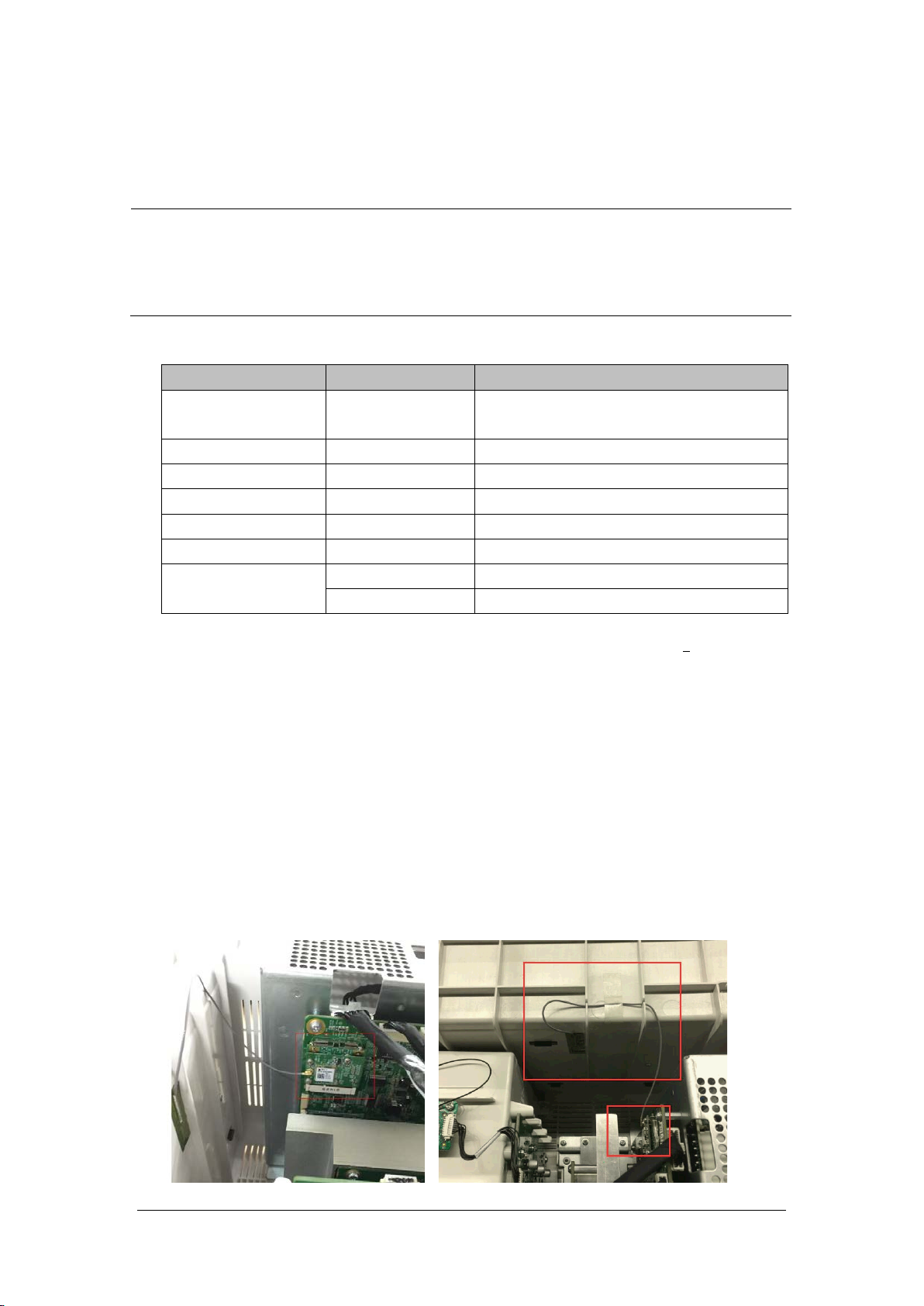
5.3 Optional Functional Assemblies
NOTE
When upgrading the wireless network, analog output and CIS function for a patient monitor
with standard configuration, you have to replace old PCBAs in the patient monitor with
corresponding PCBAs included in the upgrade kit and remove the covers of related connectors
in addition to installing the corresponding functional assemblies in the monitor.
Available functional upgrade options are:
Functional Assembly PN Name and Specification
SMR 115-033887-00
Recorder 115-044523-00 Recorder upgrade package
Wi-Fi 115-044521-00 2.4G/5G Wifi upgrade package
MPAN 115-044522-00 MPAN upgrade package
iView 115-050002-00
Independent Display 115-044554-00 ID upgrade package (Without MainBoard)
115-039575-00 2D Barcode scanner (USB) kit
2D barcode scanner
115-039635-00 2D Barcode scanner (support RFID) kit
This monitor is configured with wireless network functions and can be connected to network through
wireless AP. Contact Mindray Technical Support for assistance in connecting to a network.
5.3.1 Installing an SMR
The SMR can be connected to the patient monitor through the SMR connector via the SMR cable.
For details, see BeneVision N Series Patient Monitor Operator's Manual (P/N: 046-011259-00).
5.3.2 Setting up Wireless Network Functions
Installation and connection to a Wireless Network should be performed by Mindray Service
8-slot satellite module rack (SMR), with handle,
hook, and 2 m cable
iView upgrade package(Win 10)
BeneVision N17/BeneVision N15/BeneVision N12 Patient Monitor Service Manual 5-3
Page 54
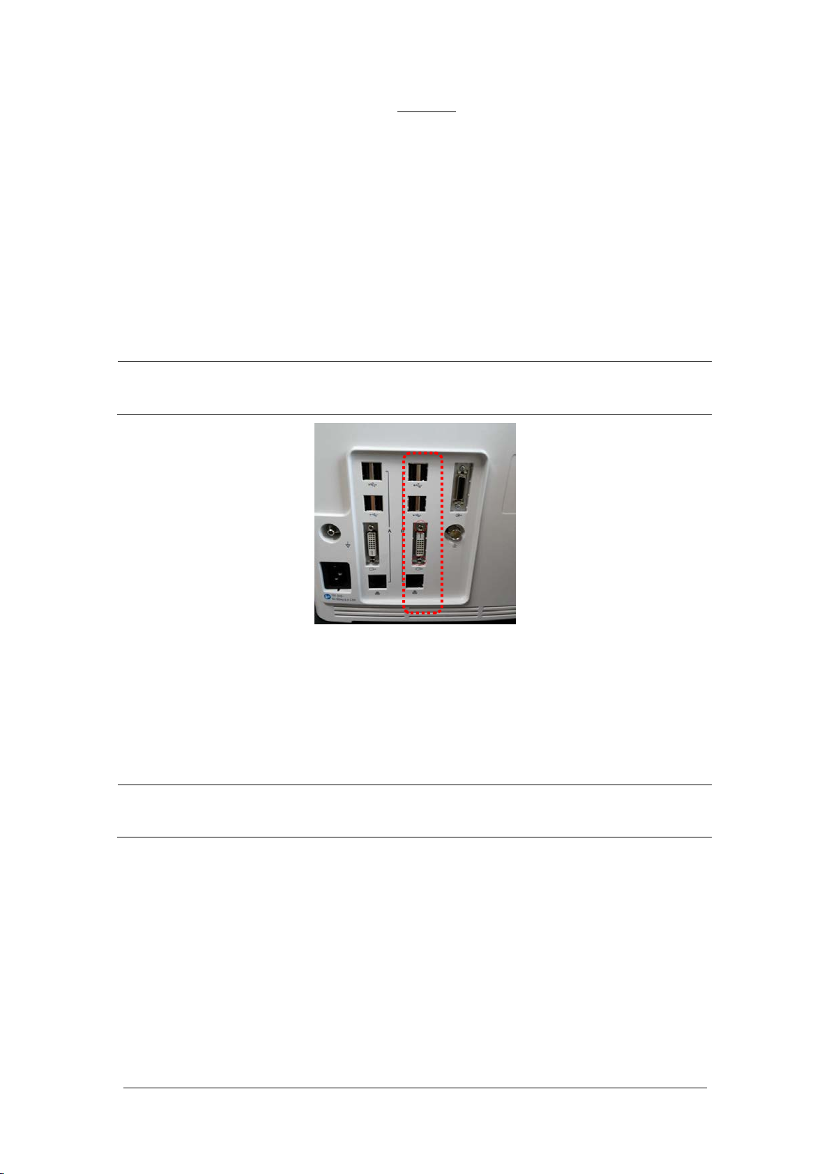
The wireless signal can be affected by incorrect inaccuracy installation location of the antenna.
5.3.3 Upgrading Recorder
Refer to the corresponding section of this manual to install the recorder in your patient monitor.
5.3.4 Upgrading iView System
Refer to the corresponding section of this manual to install the related boards of the iView upgrade
package in your patient monitor.
NOTE
During installation, use a blade to cut off the seals for the USB, DVI and network interface at
the rear case so that the interface can stretch out from the rear case.
5.3.5 Upgrading Independent Display Function
Refer to the corresponding section of this manual to install the related boards of the independent display
upgrade package in your patient monitor.
NOTE
During installation, use a blade to cut off the DVI seal at the rear case so that the interface can
stretch out from the rear case.
5-4 BeneVision N17/BeneVision N15/BeneVision N12 Patient Monitor Service Manual
Page 55

BeneVision N17/BeneVision N15/BeneVision N12 Patient Monitor Service Manual 5-5
Page 56

FOR YOUR NOTES
5-6 BeneVision N17/BeneVision N15/BeneVision N12 Patient Monitor Service Manual
Page 57

6 Repair and Disassembly
6.1 Tools
During disassembly and repair, the following tools may be required:
Phillips screwdrivers
Small flat-bladed screwdriver (specification 101 or 102)
Contact spanner (6800-J95)
Tweezers
Needle nose pliers
M3 sleeve
6.2 Preparations for Disassembly
Before disassembling the monitor, make following preparations:
Stop monitoring the patient, turn off the monitor and disconnect all the accessories and peripheral
devices.
Disconnect the AC power supply and take out all the batteries.
Remove all the parameter modules in the integral module rack;
if the SMR is connected, disconnect the SMR from the monitor and then remove all the parameter
modules in it.
CAUTION
Eliminate static electricity before the disassembly. When removing some parts with the
electrostatic sensitive mark, wear protective devices such as electrostatic ring or
anti-electrostatic gloves, lest the parts would be damaged.
Properly connect and route the cables and wires when reassembling the equipment to avoid
pinched hoses and electrical short circuits.
Use specified screws to reassemble the equipment. If the incorrect screws are forcefully
tightened, the equipment may be damaged and the screws or part may fall off during use,
causing unpredictable equipment damage or human injury.
Be sure to follow the correct sequence when disassembling the monitor.
Before removing assemblies, make sure that all the cables have been unplugged. During
removal, note to avoid breaking the cable by pulling or damaging the connector.
BeneVision N17/BeneVision N15/BeneVision N12 Patient Monitor Service Manual 6-1
Page 58

CAUTION
Place the removed screws and other parts separately by category so that they can be used in
the re-installation. Do not drop, contaminate or lose them.
6.3 Main Unit Disassembly
6.3.1 Basic Disassembly
1. Remove the power plug anti-pull hook from the rear case of the monitor.
2. Use a pair of tweezers to pry up the four screw covers at the four corners of the rear case and loosen and
remove the four M3×8 screws under them.
(Screw covers) (Screws)
6-2 BeneVision N17/BeneVision N15/BeneVision N12 Patient Monitor Service Manual
Page 59

6.3.2 Disconnecting the Base
NOTE
When laying the monitor face down on, ensure the surface is static free and non-abrasive in
order to avoid damaging the touch screen.
Be sure to remove the base first before proceeding with other parts.
1. As shown in the figure below, place the monitor face up, unscrew the M4×8 screws (5 for the N12
series and 6 for the N15N17 series) from the bottom case;
2. Pull out the base.
For the N12 series machines, the base assembly can be removed when the base is pulled out.
BeneVision N17/BeneVision N15/BeneVision N12 Patient Monitor Service Manual 6-3
Page 60

For the N15N17 series machines, the base assembly can be removed when the cable connected
to the battery interface board of main board is pulled out.
J24
J20
NOTE
Use caution when removing the Base so as not to damage the connectors and cables.
6.3.3 Separating the Front and Rear Half of the Monitor
1. After the base assembly is removed, carefully place the monitor face down.
NOTE
When laying the monitor face down on, ensure the surface is static free and non-abrasive in
order to avoid damaging the touch screen.
Release the clip (if any) on the cable socket before disconnecting the cable. Be sure to pull out
the base with proper force, without damaging the cables and connectors.
For the N12 series machines, remove the cable for the LCD screen and the cable for the small
board of front case.
6-4 BeneVision N17/BeneVision N15/BeneVision N12 Patient Monitor Service Manual
Page 61

For the N15N17 series machines, remove the cable for the touch screen, cable for the LCD screen
and the cable for the small board of front case.
2. Lift the rear case assembly to separate it from the front case assembly.
NOTE
As shown in the following figure, there are two types of front case assemblies (NLT or SHARP).
Cable connections differ between NLT and SHARP.
N12
(N12 rear case assembly)
(N12-NLT front case assembly) (N12-SHARP front case assembly)
BeneVision N17/BeneVision N15/BeneVision N12 Patient Monitor Service Manual 6-5
Page 62
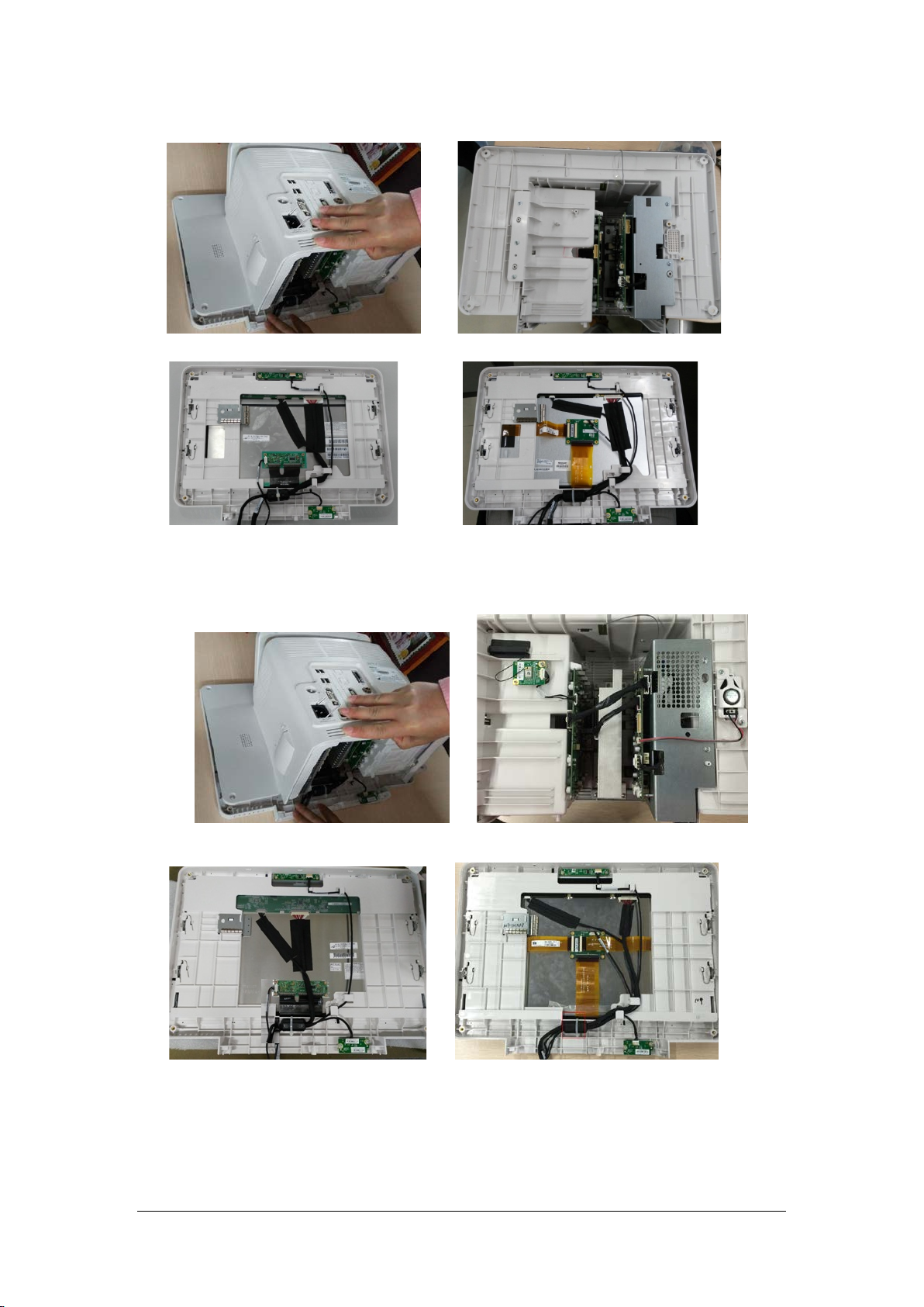
N15
(N15 rear case assembly)
(N15-NLT front case assembly) (N15-SHARP front case assembly)
N17
(N17 rear case assembly)
(N17-NLT front case assembly) (N17-SHARP front case assembly)
6-6 BeneVision N17/BeneVision N15/BeneVision N12 Patient Monitor Service Manual
Page 63
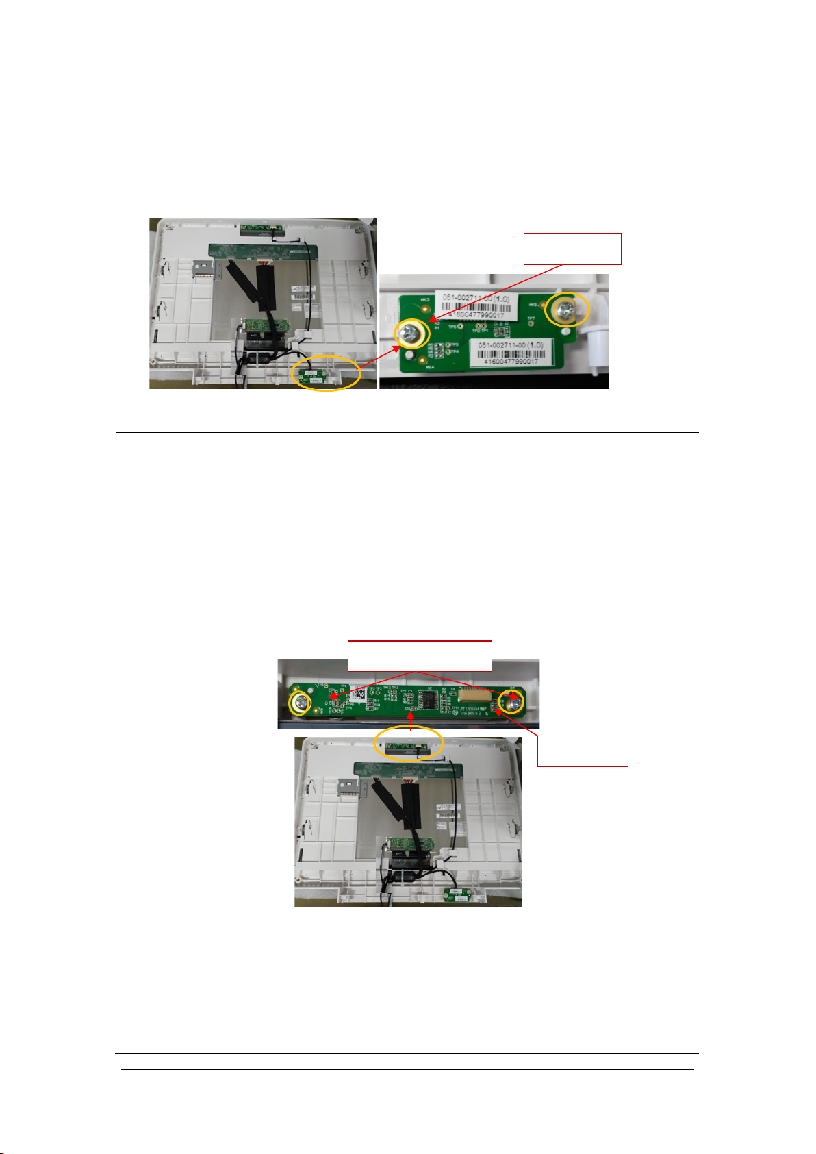
6.4 Further Disassembly of the Front Case Assembly
6.4.1 Removing the Power Switch Board
1. Remove the cable on the power switch board.
2. Remove the two PT3×8 screws and take out the power switch board.
2 pcs
NOTE
Use care when disconnecting the cable to avoid damage. During installation, press the
board to the silicone keypad direction by aligning with the front case board positioning rib.
Use care to avoid overtightening the screws and stripping the holes when remounting the
board.
6.4.2 Removing the Alarm Lamp and Light Sensor Board
1. Remove the cable on the alarm lamp and light sensor board.
2. Remove the two PT3×8 screws and take out the alarm lamp and light sensor board.
2 pcs PT3X8
Cable socket
NOTE
Use care when disconnecting the cable to avoid damage.
During installation, press the board to the alarm lamp shade direction by aligning with the
front case board positioning rib.
Use care to avoid overtightening the screws and stripping the holes when remounting the
board.
BeneVision N17/BeneVision N15/BeneVision N12 Patient Monitor Service Manual 6-7
Page 64

6.4.3 Removing the Screen Assembly Cables
1. Cut the cable tie and disconnect the cables connected to the display screen and touch screen control
board. All the cables can be removed by releasing the cable clamps on the front case.
Cable tie
(N12-NLT ) (N12-SHARP)
Cable tie
(N15-NLT ) (N15-SHARP)
Cable tie
(N17-NLT ) (N17-SHARP)
CAUTION
Prevent pressure on the front face of display screen during disassembly.
Remove the LCD screen assembly in an environment as dust-free as possible; the display screen
and touch screen are integrated materials and cannot be disassembled.
6-8 BeneVision N17/BeneVision N15/BeneVision N12 Patient Monitor Service Manual
Page 65

NOTE
6.5 Further Disassembly of the Rear Case Assembly
6.5.1 Removing the Recorder
1. First open the recorder door on the right of the machine, and then unscrew the two M3×6 screws.
2. Pull the two clips in as indicated in the figure below to separate it from the rear case, and pull out the
recorder at the same time.
3. After the recorder is pulled out, remove the Recorder Cable from the Positioning Rib and disconnect the
cable from the Recorder. The Recorder can now be removed.
M3X6
Clips
Use care when disconnecting the cable to avoid damage.
6.5.2 Further Disassembly of the Recorder
1. First remove one PT2X6 screw, and remove the grounding piece at the same time.
Positioning rib
M2X6
BeneVision N17/BeneVision N15/BeneVision N12 Patient Monitor Service Manual 6-9
Page 66

Connector cable
2. Release the two clips backward and take out the recorder drive board. Pay attention to the snap in
the front.
Snap
3. First pull up the connector cable lock by about 1 mm to remove the flexible cable; remove the cable
from the drive board to the button board; unscrew one PT2×6 screw, and remove the ground cable
of the drive board. Remove the recorder drive board.
4. Remove the other PT2×6 screw and take out the thermal printhead.
5. Loosen and remove the two PT2×6 screws and remove the button board of recorder.
Recorder button
Thermal print head
NOTE
Use care when disconnecting the cable to avoid damage.
6-10 BeneVision N17/BeneVision N15/BeneVision N12 Patient Monitor Service Manual
Page 67

6.5.3 Removing the Bluetooth Board
1. Pull out the MPAN board cable at the end of internal module rack communication board; then pull
out the MPAN antenna connector inserted on the Bluetooth board; unscrew one M3×6 screw to
remove the MPAN board.
2. Tear the MPAN antenna fixing piece. Then, the MPAN antenna can be removed.
NOTE
Use care when disconnecting the cable to avoid damage.
BeneVision N17/BeneVision N15/BeneVision N12 Patient Monitor Service Manual 6-11
Page 68

6.5.4 Removing the Wi-Fi Module
1. Press the clips at two sides of the Wi-Fi socket, and take out the Wi-Fi module from the socket.
2. Remove the adhesive tape fixing the antenna, and tear off the Wi-Fi sticker antenna.
3. Pull out the Wi-Fi antenna plug from the board; unscrew the three M2X4 screws, and separate the
Wi-Fi module from the Wi-Fi support board.
Wi-Fi module
Wi-Fi support board
6-12 BeneVision N17/BeneVision N15/BeneVision N12 Patient Monitor Service Manual
Page 69

NOTE
Use care when disconnecting the cable to avoid damage.
Use care when removing the Wi-Fi Module from the Wi-Fi Support board to avoid
damage to the connector.
that you maintain your product better.
Provides application tips or other useful information to ensure
6.5.5 Removing the Internal Module Rack Assembly
NOTE
Release the cable clips on the socket before attempting to disconnect the cable. Failure to do
so will damage the cable.
N12
1. Disconnect the battery interface cable from the main board, then disconnect the internal module
rack COMM board cable. Remove four M3x6 screws and lift up to remove the battery holder
assembly.
Cable of battery interface board
J10
J20
Cable of internal module
rack COMM board
2. Loosen and remove the two M3X6 screws, and remove the battery interface board.
BeneVision N17/BeneVision N15/BeneVision N12 Patient Monitor Service Manual 6-13
Page 70

3. Loosen and remove the five M3X6 screws, and lift upward to remove the internal module rack
assembly as indicated in the figure.
4. Place the face of the removed module rack assembly board up. First unscrew the two M2.5X6 screws
on the SMR interface, the two PT3X8 screws, and the six M3X6 screws in turn, and then remove the
internal module rack COMM board.
M3X6
M2.5X
SMR interface sheet metal
5. Turn over the removed internal module rack COMM board, and remove the four POGO PIN silicon
cases.
PT3X8
6-14 BeneVision N17/BeneVision N15/BeneVision N12 Patient Monitor Service Manual
Page 71

N15N17
1. First remove the cable of internal module rack COMM board; unscrew the four M3X6 screws
according to the positions shown below, and loosen one captive screw; force upward to remove the
module rack assembly as indicated in the figure.
Cable of internal module rack COMM board
One captive screw
2. Place the face of the removed module rack assembly board up. First unscrew the two M2.5X6 screws
on the SMR interface, the two PT3X8 screws, and the seven M3X6 screws in turn, and then remove
the internal module rack COMM board.
M2.5X
M3X6
PT3X8
BeneVision N17/BeneVision N15/BeneVision N12 Patient Monitor Service Manual 6-15
Page 72

3. Turn over the removed internal module rack COMM board, and remove the six POGO PIN silicon
cases.
6.5.6 Removing the Main Support Assembly (N12& N15)
N12
1. Disconnect the Speaker cable, unscrew the two M3X6 screws, and remove the speaker assembly.
Speaker cable
2. Loosen and remove the five M3X6 screws, and vertically take out the main support assembly.
6-16 BeneVision N17/BeneVision N15/BeneVision N12 Patient Monitor Service Manual
Page 73

3. As shown in the figure below, after removing the main support assembly, place the main control
board with face upwards. Remove the cable between the main control board and the ACDC power
supply board., Unscrew the two DVI stud screws and four M3X6 screws, and then take out the main
control board.
Cable from the main
control board to the
ACDC Power Supply
4. Turn over the main support assembly with the ACDC power supply board facing up. Disconnect the
other end of the cable between the main board and the ACDC power supply board. Then disconnect
the cable between the AC input to the ACDC power supply board. . Unscrew four M3X6 screws, and
remove the power board.
DVI stud screw
Cable between the AC
input to the ACDC power
supply board
Cable from the main
control board to the
ACDC Power Supply
BeneVision N17/BeneVision N15/BeneVision N12 Patient Monitor Service Manual 6-17
Page 74
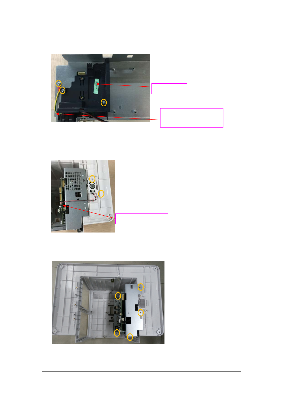
5. Loosen and remove two M3X6 screws and take out the recorder cover. Unscrew one M3X6 screw, and
remove the cable from the AC input to ACDC power supply board.
Recorder cover
Cable from the AC input to
N15/N17
1. Disconnect the speaker cable. Loosen and remove the two M3X6 screws, and remove the speaker
assembly.
ACDC Power Supply
Speaker cable
2. As shown below, for the N15 series machine, loosen and remove the five M3X6 screws, and lift out the
main support assembly.
(N15)
6-18 BeneVision N17/BeneVision N15/BeneVision N12 Patient Monitor Service Manual
Page 75

As shown below, for the N17 series machine, loosen and remove the six M3X6 screws, and lift out the
main support assembly.
(N17)
3. As shown in the figure below, after removing the main support assembly, place the main control
board with face upwards. Remove the cable between the main control board and the ACDC power
supply board. Unscrew the two DVI stud screws and four M3X6 screws, and then take out the main
control board.
Cable from the main control board
to the ACDC
4. Turn over the main support assembly with the ACDC power supply board facing up. Disconnect the
other end of the cable between the main board and the ACDC power supply board. Then disconnect
the cable between the AC input to the ACDC power supply board. Unscrew and remove the four
M3X6 screws, and remove the power board.
Cable from the main control board
to the ACDC
Power board
AC input to ACDC power cord
BeneVision N17/BeneVision N15/BeneVision N12 Patient Monitor Service Manual 6-19
Page 76
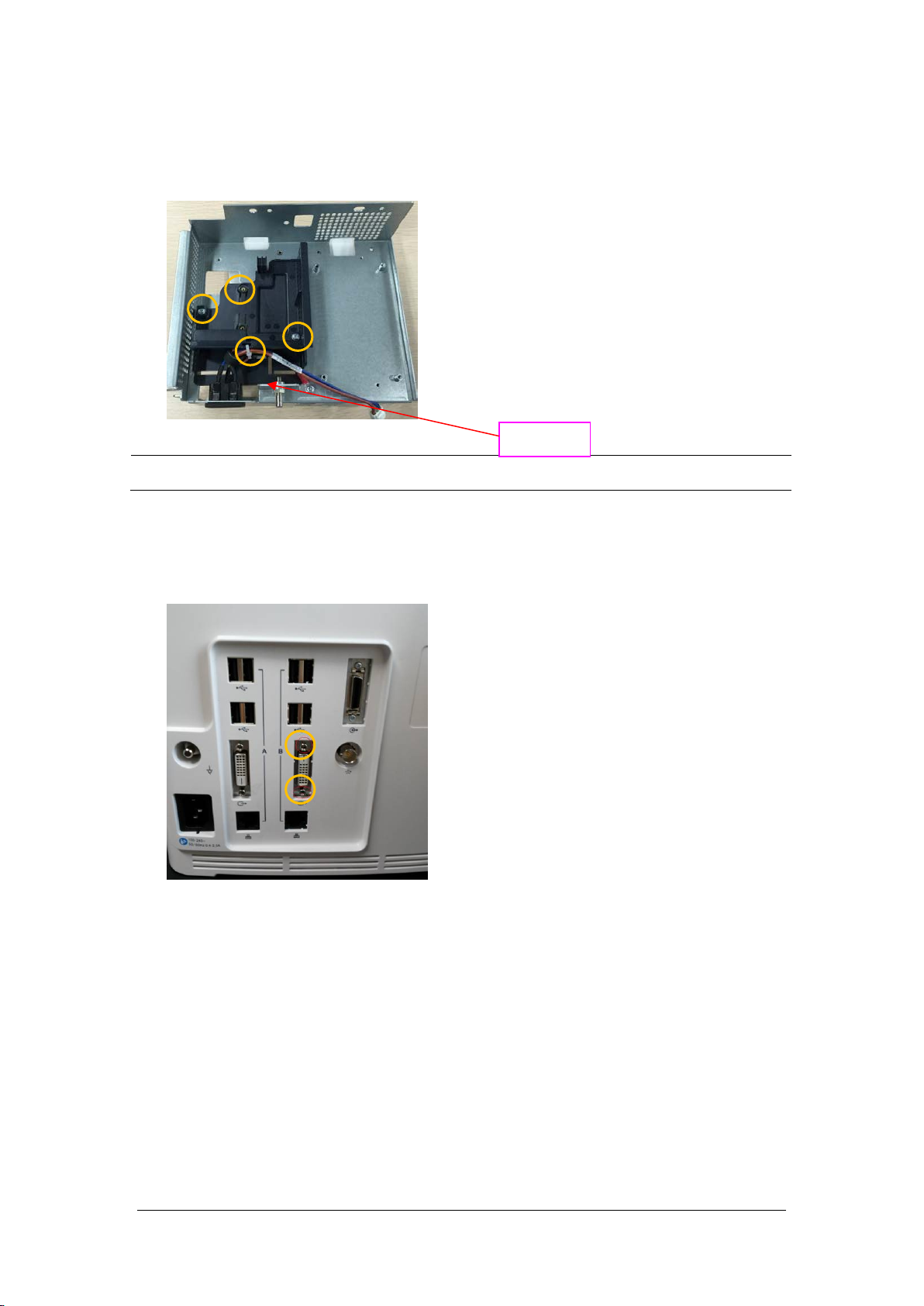
5. Cut off the cable tie on the cable. Unscrew and remove the two M3X6 screws, and take out the
recorder cover. Unscrew and remove one M3X6 screw, and remove the cable from the AC Input
Connector to the ACDC Power Supply.
NOTE
Use care not to damage the cable when cutting the tie.
Cable tie
6.5.7 Removing the iView Board Assembly (N17)
1. First unscrew the two DVI stud screws.
6-20 BeneVision N17/BeneVision N15/BeneVision N12 Patient Monitor Service Manual
Page 77

2. Remove the two iView board cable and the internal module rack cable. Loosen and remove the four
M3X6 screws, and then take out the iView board assembly.
Two iView board cables
3. Place the face of the removed iView board assembly board up, and remove the SSD hard disk by
pressing the SSD hard disk clips; loosen and remove the four M3X6 screws, and remove the iView
board.
SSD hard disk clips
4. As shown below, place up the face of the iView board side with the computer module. Loosen and
remove the four M2X6 screws, and separate the computer module from the iView support board.
Computer
module
iView support
board
BeneVision N17/BeneVision N15/BeneVision N12 Patient Monitor Service Manual 6-21
Page 78

6.5.8 Removing the Independent Display Board Assembly (N17 Series)
1. First unscrew the two DVI stud screws.
2. Remove the independent display board cable and the internal module rack cable. Loosen and
remove the four M3X6 screws, and then remove the independent display board assembly.
3. Loosen and remove the four M3X6 screws, and remove the independent display board.
6-22 BeneVision N17/BeneVision N15/BeneVision N12 Patient Monitor Service Manual
Page 79

6.5.9 Removing the Handle
1. Place the face of the rear case handle down. Loosen and remove the two PT 3X8 screws, forcibly
release the four clips on the top cover of rear case, and push down to take out the top cover of rear
case.
2. Pry the two handle pins towards the center of the case, then remove the handle.
BeneVision N17/BeneVision N15/BeneVision N12 Patient Monitor Service Manual 6-23
Page 80
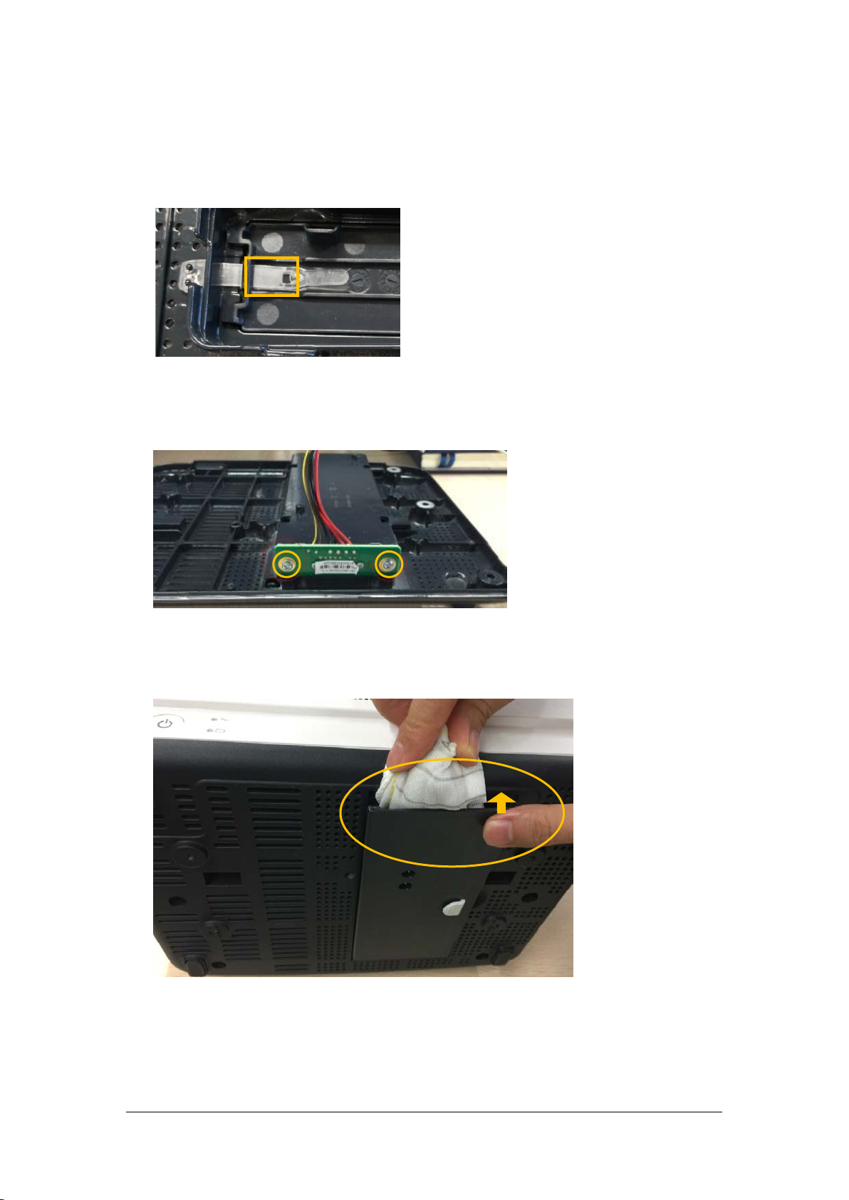
6.6 Further Disassembly of the Base Assembly
N12
Remove the battery door connecting belt from the through hole, and remove the battery door.
N15/N17
1. Loosen and remove the two M3X6 screws, and remove the battery interface board.
2. As shown below, open the battery door, insert a pad between the battery door and the base and
press down firmly to remove the battery door.
6-24 BeneVision N17/BeneVision N15/BeneVision N12 Patient Monitor Service Manual
Page 81

6.7 Disassembling the Module Rack
M3X8 screw
1. Removing the handle and hooks
As shown in the following figure, loosen and remove the eight M3X10 cross recessed screws, and
remove the hooks.
M3X10
As shown in the following figure, loosen and remove the three M3×8 cross recessed screws, and
remove the handle.
BeneVision N17/BeneVision N15/BeneVision N12 Patient Monitor Service Manual 6-25
Page 82
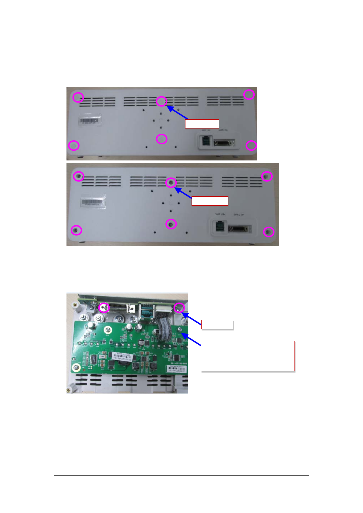
2. Removing the rear case of module rack
As shown in the following figure, use a tweezer to take out the six screw covers on the rear case.
Loosen and remove the six M3X16 cross recessed pan head screws, and separate the front case from
the rear case.
Screw cover
M3X16 screw
3. Removing the module rack interface board
Loosen and remove the two M3X8 cross recessed pan head screws, disconnect the cable between the
interface board and the internal module rack COMM board, and then remove the interface board.
M3X8 screw
Cable from the interface board of
external module rack to the 8-slot board
6-26 BeneVision N17/BeneVision N15/BeneVision N12 Patient Monitor Service Manual
Page 83

4. Removing the internal module rack COMM board.
Disconnect the cable between the module rack antenna and the internal module rack COMM board.
Loosen and remove the seven M3X8 cross recessed pan head screws on the internal module rack
COMM board, and remove the eight POGO PIN silicon cases from the module rack.
Module rack antenna
M3X6 screw
POGO PIN silicon cases of
module rack
BeneVision N17/BeneVision N15/BeneVision N12 Patient Monitor Service Manual 6-27
Page 84

6.8 Disassembling the MPM Module
1. Removing the front panel assembly
As shown in the figure, use a contact wrench to remove the screw for the back end terminal of
the module; use a small flat-bladed screwdriver to remove the module retention tabs. Use a
Phillips screwdriver to remove the front panel screw. Then, the front panel of module can be
removed.
Use a contact wrench to
remove the terminal screw
As shown in the following figure, loosen and remove the screw between the front panel and the
bracket, and unplug the air tube at the air nozzle. Then the front panel can be removed.
Remove the module
retention tabs
Remove the screw
Remove the
bracket screw
2. Remove the parameter board
As shown in the following figure, loosen and remove the board screws. Remove pull out the pump
and valve cable and NIBP air tube. Then, the parameter board can be removed.
Parameter board screws and
cable
Remove along this direction
6-28 BeneVision N17/BeneVision N15/BeneVision N12 Patient Monitor Service Manual
Page 85

Cut the
cable tie
Release the clips
Disconnect power lines
3. Removing the blood oxygen board
As shown in the following figure, remove the blood oxygen board screws, and then remove the blood
oxygen board.
Remove the screws here
4. Removing the infrared board
As shown in the following figure, remove the infrared board cable and then remove the infrared
board.
Remove from this end
5. Removing the pump and valve
Cut the cable tie, disconnect the pump power cable and NIBP air tube, and then remove the pump.
Disconnect the valve power cable and NIBP air tube, use a flat-bladed screwdriver to release the clips
on the sides of the valve, and then remove the valve assembly.
s
BeneVision N17/BeneVision N15/BeneVision N12 Patient Monitor Service Manual 6-29
Page 86

FOR YOUR NOTES
6-30 BeneVision N17/BeneVision N15/BeneVision N12 Patient Monitor Service Manual
Page 87

7 Parts
This chapter lists the exploded views and material codes of the parts including the monitor's main unit,
SMR and parameter module. It helps the engineer to identify the parts during disassembly of the patient
monitor and spare parts replacement.
7.1 N12 Parts
7.1.1 N12 Whole Unit
7.1.1.1 Exploded View
7.1.1.2 Parts List
ITEM No. Description Qty FRU Part No.
1
2 N12rear housing assembly (with TDS/BNC, with DVI) 1 /
3 N12 screw cover / 049-001226-00
4 Cross recessed pan head screw, GB/T818-2000 M4X30 / /
5 AC inlet hook 1 9211-20-87369
BeneVision N17/BeneVision N15/BeneVision N12 Patient Monitor Service Manual 7-1
N12-NLT front housing assembly (FRU) 1 115-044502-00
N12-Sharp front housing assembly (FRU) 1 115-044503-00
Page 88
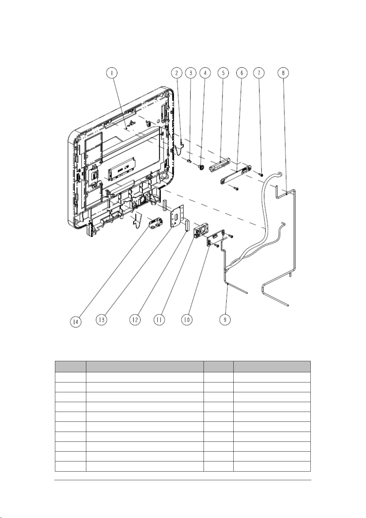
7.1.2 N12-NLT Front Housing Assembly
7.1.2.1 Exploded View
7.1.2.2 Parts List
ITEM No. Description Qty FRU Part No.
1 N12-NLT front housing assembly (FRU) 1 115-044502-00
2 Screen clip 2 033-000636-00*
3 Light guild pillar 1 043-007582-00
4 MK hood 1 049-001214-00
5 MK alarm cap 1 049-001135-00
6 Alarm LED and Light Sensor Board PCBA 1 051-002693-00
7 Cross recessed pan head screws, PT3X8 4 /
8 N12 front shell plate cable 1 009-006396-00*
9 N12 Mainboard to LCD cable (NLT) 1 009-006410-00*
10 Power Switch and Indicate LED Board PCBA 1 051-002711-00
7-2 BeneVision N17/BeneVision N15/BeneVision N12 Patient Monitor Service Manual
Page 89

ITEM No. Description Qty FRU Part No.
11 MK power button (P+R) 1 043-007956-01
12 Conductive cloth pad 0.08m /
13 Earth plate (N12) 1 042-018667-00*
14 CORE O.D=21.5mmI.D=9.5mm 1 /
*: included in No.1 N12-NLT front housing assembly (FRU) (115-044502-00).
7.1.3 N12-Sharp Front Housing Assembly
7.1.3.1 Exploded View
7.1.3.2 Parts List
ITEM No. Description Qty FRU Part No.
1 N12-Sharp front housing assembly (FRU) 1 115-044503-00
2 Screen clip 2 033-000636-00*
3 Light guild pillar 1 043-007582-00
4 MK hood 1 049-001214-00
BeneVision N17/BeneVision N15/BeneVision N12 Patient Monitor Service Manual 7-3
Page 90

ITEM No. Description Qty FRU Part No.
5 MK alarm cap 1 049-001135-00
6 Alarm LED and Light Sensor Board PCBA 1 051-002693-00
7 Cross recessed pan head screws PT3X8 4 /
8 N12 front shell plate cable 1 009-006396-00*
9 N12 Mainboard to LCD cable (NLT) 1 009-006409-00*
10 Power Switch and Indicate LED Board PCBA 1 051-002711-00
11 MK power button (P+R) 1 043-007956-01
12 Earth plate (N12) 1 042-018667-00*
13 Conductive cloth pad 0.08m /
14 CORE O.D=21.5mmI.D=9.5mm 1 /
*: included in No.1 N12-Sharp front housing assembly (FRU) (115-044503-00)
7.1.4 N12 Rear Housing
7.1.4.1 Exploded View
7-4 BeneVision N17/BeneVision N15/BeneVision N12 Patient Monitor Service Manual
Page 91

7.1.4.2 Parts List
ITEM No. Description Qty FRU Part No.
1 N12 handle 1
2 Cushion pad /
3 N12 top cover 1 043-007578-01
4 Waterproof strip N12 1 048-006308-00
5 Handle Left Damping Block, N12 1 /
6 N12 rear housing (silk screen) 1 043-008005-01
7 N12 internal module rack assembly (with TDS/BNC) 1 /
8 Speaker bracket 1 115-044509-00
9 Speaker 2W 4ohm 500Hz 1
10 MK speaker foam 1
11 Cross recessed pan head screw, M3X6 with pad / /
12 N12 main bracket assembly (with DVI) 1 /
13 TR6F recorder 1 /
14 Handle Right Damping Block, N12 1 /
15 Self-Clinching Pilot Pins.TPS-3-18 / /
16 Screw cap 2(T8) / 049-000650-00
17 Cross recessed pan head crews,PT3X8 / /
18 Conductive foam 2.0*7.0mm / /
115-044501-00
BeneVision N17/BeneVision N15/BeneVision N12 Patient Monitor Service Manual 7-5
Page 92

7.1.5 N12 Rear Housing Assembly (FRU)(115-044499-00)
7.1.5.1 Exploded View
7.1.5.2 Parts List
ITEM No. Description Qty FRU Part No.
1 N12 rear housing (silk screen) 1 043-008005-01
2 Handle Right Damping Block, N12 1 049-001250-00
3 Screw cap 2(T8) 3 /
4 Waterproof strip N12 1 048-006308-00
5 Handle Left Damping Block, N12 1 049-001249-00
6 Conductive foam 2.0*7.0 mm 0.11m /
7-6 BeneVision N17/BeneVision N15/BeneVision N12 Patient Monitor Service Manual
Page 93

7.1.6 N12 Battery Cavity Assembly (FRU)(115-044504-00)
7.1.6.1 Exploded View
7.1.6.2 Parts List
ITEM No. Description Qty FRU Part No.
1 N12 battery cavity 1 /
2
3 Battery bar 1 9211-20-87256
4 Battery bar sleeve 1 /
5 Cushion pad.Bumpon SJ5302, white and transparent 1 /
Cross recessed pan head screw GB/T818-2000 M4X30
plated with green color zinc
1 /
BeneVision N17/BeneVision N15/BeneVision N12 Patient Monitor Service Manual 7-7
Page 94

7.1.7 N12 Module Rack Body Assembly (FRU) (115-044507-00)
7.1.7.1 Exploded View
7.1.7.2 Parts List
ITEM No. Description Qty FRU Part No.
1 N12 module rack (four slots) 1 /
2 Infrared lens 4 047-005213-00
3 Contact screw 8 6800-21-51100
4 Contact spring 8 6800-20-50261
5 Spring 8 6800-20-50388
6 Flat washer 8 /
7 Hex nut and taper lock washer assembly, M3 8 /
7-8 BeneVision N17/BeneVision N15/BeneVision N12 Patient Monitor Service Manual
Page 95
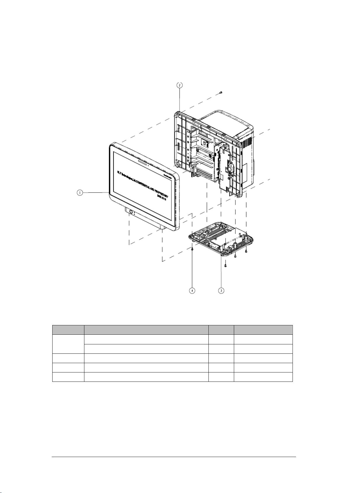
7.2 N 15 Parts
7.2.1 N15 Whole Unit
7.2.1.1 Exploded View
7.2.1.2 Parts List
ITEM No. Description Qty FRU Part No.
1
2 N15 rear housing assembly (with SMR/BNC) 1 /
3 N15 base assembly (FRU) 1 115-044543-00
4 Screw / /
BeneVision N17/BeneVision N15/BeneVision N12 Patient Monitor Service Manual 7-9
N15-NLT front housing assembly (FRU) 1 115-044544-00
N15-Sharp front housing assembly (FRU) 1 115-044545-00
Page 96
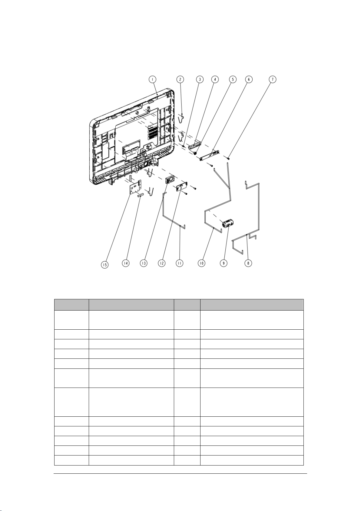
7.2.2 N15-NLT Front Housing Assembly
7.2.2.1 Exploded View
7.2.2.2 Parts List
ITEM No. Description Qty FRU Part No.
1
2 Screen clip 4 033-000636-00*
3 Light guild pillar 1 043-007582-00
4 MK alarm cap 1 049-001135-00
5 MK hood 1 049-001214-00
6
7
8 N15N17 front shell plate cable 1 009-006736-00*
9 CORE O.D=21.5mmI.D=9.5mm 1 1 /
10 N15 Mainboard to LCD cable (NLT) 1 009-006408-00*
11 N15N17 touch screen cable (NLT) 1 009-006397-00*
12 Power Switch and Indicate LED 1 051-002711-00
N15-NLT Front Housing Assembly
(FRU)
Alarm LED and Light Sensor Board
PCBA
Cross recessed pan head
thread-cutting tapping screws
PT3X8 plated with green color zinc
1 115-044544-00
1 051-002693-00
4 /
7-10 BeneVision N17/BeneVision N15/BeneVision N12 Patient Monitor Service Manual
Page 97

ITEM No. Description Qty FRU Part No.
Board PCBA
13 MK power button (P+R) 1 043-007956-01
14 Conductive cloth pad 0.08m /
15 Earth plate (NLT) 1 042-017398-00*
*: included in No.1 N15-NLT front housing assembly (FRU) (115-044544-00)
7.2.3 N15-Sharp Front Housing
7.2.3.1 Exploded View
7.2.3.2 Parts List
ITEM No. Description Qty FRU Part No.
1 N15-Sharp front housing assembly (FRU) 1 115-044545-00
2 Screen clip 4 033-000636-00*
3 Light guild pillar 1 043-007582-00
4 MK alarm cap 1 049-001135-00
5 MK hood 1 049-001214-00
BeneVision N17/BeneVision N15/BeneVision N12 Patient Monitor Service Manual 7-11
Page 98

ITEM No. Description Qty FRU Part No.
6 Alarm LED and Light Sensor Board PCBA 1 051-002693-00
7 Cross recessed pan head screws,PT3X8 4 /
8 N15N17 front shell plate cable 1 009-006736-00*
9 CORE O.D=21.5mmI.D=9.5mm 1 1 /
10 N15 Mainboard to LCD cable (Sharp) 1 009-006407-00*
11 N15N17 touch screen cable (Sharp) 1 009-006730-00*
12 Power Switch and Indicate LED Board PCBA 1 051-002711-00
13 MK power button (P+R) 1 043-007956-01
14 Conductive cloth pad 0.08m /
15 Earth plate (N15-Sharp) 1 042-018592-00*
*: included in No.1 N15-Sharp front housing assembly (FRU) (115-044545-00)
7.2.4 N15 Rear Housing
7.2.4.1 Exploded View
7-12 BeneVision N17/BeneVision N15/BeneVision N12 Patient Monitor Service Manual
Page 99

7.2.4.2 Parts List
ITEM No. Description Qty FRU Part No.
1 N15 rear housing 1 043-008003-01
2 Handle left damping block, N15 1 /
3 N15 top cover 1 043-007566-01
4 N15 handle 1
5 Cushion pad 1
6 Blind rivet hole BSO-3.5M3-28 ZC 2
7 Handle right damping block, N15 1 /
8 Cross recessed pan head thread-cutting tapping
screws PT3X8 plated with green color zinc
9 Recorder door 1 043-008499-00
10 MK speaker foam 1 115-044547-00
11 Speaker 2W 4ohm 500Hz 1
12 Speaker bracket 1
13 N 15 main bracket assembly (with DVI) 1 /
14 N15N17 module rack assembly (with SMR/BNC) 1 /
15 Screw / /
16 Conductive foam 2.0*7.0mm / /
/ /
115-044542-00
BeneVision N17/BeneVision N15/BeneVision N12 Patient Monitor Service Manual 7-13
Page 100

7.2.5 N15 Rear Housing Assembly (FRU) (115-044541-00)
7.2.5.1 Exploded View
7.2.5.2 Parts List
ITEM No. Description Qty FRU Part No.
1 N15 rear housing (silk screen) 1 043-008003-01
2 Waterproof foam (N15) 1 048-006291-00
3 N15 Handle Right Damp 1 049-001283-00
4 N15 Handle Left Damp 1 049-001284-00
5 Conductive foam 2.0*7.0 mm 3 /
7-14 BeneVision N17/BeneVision N15/BeneVision N12 Patient Monitor Service Manual
 Loading...