

Mindray H-046-010876-00-BeneVision-CMS-Service-Manual-R3-6.0 BeneVision Central Monitoring System Viewer Installation Guide
Page 1

BeneVision
Central Monitoring System
Service Manual
Page 2

Page 3

WARNING
NOTE
Intellectual Property Statement
SHENZHEN MINDRAY BIO-MEDICAL ELECTRONICS CO., LTD. (hereinafter called Mindray) owns the intellectual
property rights to this Mindray product and this manual. This manual may refer to information protected by
copyrights or patents and does not convey any license under the patent rights of Mindray, nor the rights of
others.
Mindray intends to maintain the contents of this manual as confidential information. Disclosure of the
information in this manual in any manner whatsoever without the written permission of Mindray is strictly
forbidden.
Release, amendment, reproduction, distribution, rental, adaption and translation of this manual in any manner
whatsoever without the written permission o f Mindray is strictly forbidden.
, , and are the registered trademarks o r trademarks owned by Mindray
in China and other countries. All other trademarks that appear in this manual are used only for editorial
purposes without the intention of improperly us ing them. They are the property of their respective owners.
This posting serves as notice under 35 U.S.C.§287(a) for Mindray patents: http://www.mindrayna.com/patents.
For this manual, th e issued Date is May2019 (Versio n: 6.0).
© 2017-2019 Shenzhen Mindray Bio-Medical Electronics Co., Ltd. All rights reserved
Federal Law (USA) restricts this device to sale by or on the o rder of a physician or other
practitioner licensed by U.S. state law to use or or der the use o f this device.
This manual describes all features and options. The equipment may not have all of them.
Contact Mindray service department for any questions.
BeneV ision CMS Service Manual I
Page 4

Manufacturer’s Responsibility
Contents of this manual are subject to changes without prior notice.
All information contained in this manual is believed to be correct. Mindray shall not be liable for errors
contained herein nor for incidental or consequential damages in connection with the furnishing, performance,
or use of this manual.
Mindray is responsible for safety, reliability and performance of this produ ct only in the condition that:
All installation operation s, ex pans ions, changes, modifications and repairs of th is product are con ducted
by Mindray authorized perso nnel; and
The electrical installatio n of the relevant room complies with the applicable national and local
requirements; and
This product is operated under strict observance of this manual.
II BeneV ision CMS Service Manual
Page 5

Return Policy
In the ev ent that it becomes necessary to return a unit to Mindray, follow the instructions below.
1. Obtain a return authorization .
Contact the Mindray Service Department and obtain a Mindray Customer Service Authorization Number. The
Mindray Customer Service Auth orization Number mu st appear on the outside of the shipping container.
Return shipments will not be accepted if the Mindray Custo mer Service Authorization Number is n ot clearly
visible. Pleas e provide the model nu mber, serial number, and a brief description of the reason for return.
2. Freight policy
The custo mer is responsible for freight charges when this p ro duct is shipped to Mindray for service (including
any relevant customs fees or oth er freight related charg es).
3. Return address
Please send the part(s) or equipment to the address offered by Customer Service Department.
Contact Information
Manufacturer: Shenzhen Mindray Bio-Medical E lectron ics Co ., Ltd.
Address: Mindray Building, Keji 12th Road South, High-tech Industrial Park, Nanshan,
Shen zhen 518057 P.R. China
Tel: +86 755 81888998
Fax: +86 755 26582680
Website: www.mindray.com
Distributor: Mindray DS USA, Inc.
Address: 800 MacArthur B oulevard M ahwah , New Jersey 07430 USA
Tel: 1.800.288.2121, 1.201.995.8000
Website: www.mindray.com
BeneV ision CMS Service Manual III
Page 6

Preface
Manual Purpose
This manual provid es detailed information abo ut the installation, maintenance, cleaning, and troubleshooting
of th e BeneV ision Central Monitoring System to su pport effective troubleshooting. It is not intended to be a
comprehensive, in-depth explanation of the product architecture or technical implementation. Use of the
manual is necessary fo r proper equipmen t maintenance and will help to eliminate equipment damage and
personal injury.
This manual is based on the maximum con figuration; therefore, some contents may not apply to your monitor.
If you have any question, please contact ou r Customer Service Department.
Intended Audience
This manual is geared for clinical professio nals wh o are expected to have a working knowledge of medical
procedures, practices and terminology as required for monitoring of critically ill patients.
Contact you r local Mindray Service Organization fo r information on product courses which address service and
support for this produ ct.
It is recommended that the user shou ld change the passwords for user maintenance once they take ownersh ip
of the equipment.
IV BeneVision CMS Service Manual
Page 7

Contents
1 Safe ty ........................................................................................................................................................................................ 1-1
1.1 Safety Information....................................................................................................................................................................................................................................... 1-1
1.1.1 Dangers............................................................................................................................................................................................................................................... 1-2
1.1.2 Warnings ............................................................................................................................................................................................................................................ 1-2
1.1.3 Cautions.............................................................................................................................................................................................................................................. 1-3
1.1.4 Notes ..................................................................................................................................................................................................................................................... 1-3
1.2 Equipment Symbols................................................................................................................................................................................................................................... 1-3
2 Introduction ............................................................................................................................................................................. 2-1
2.1 Overview ............................................................................................................................................................................................................................................................. 2-1
2.2 Intellectual Property Protection....................................................................................................................................................................................................... 2-1
2.3 Ve rsions ................................................................................................................................................................................................................................................................ 2-2
3 System Inst alla tion .................................................................................................................................................................. 3-1
3.1 Pre-installation Preparations............................................................................................................................................................................................................... 3-1
3.1.1 Environmental Requirements........................................................................................................................................................................................... 3-1
3.1.2 Power Requirements................................................................................................................................................................................................................ 3-1
3.1.3 Power and Heat Requirements........................................................................................................................................................................................ 3-2
3.2 CMS Host............................................................................................................................................................................................................................................................. 3-3
3.2.1 Kontron KISS 2U (023-001020-00)................................................................................................................................................................................. 3-3
3.2.2 HPE DL360 Gen9 (023-001671-00)/HPE DL360 Gen10(023-001839-00) ..................................................................................... 3-5
3.2.3 HP EliteDesk 800 G1 SFF (023-000969-00) ............................................................................................................................................................. 3-7
3.2.4 HP EliteDesk 800 G2 SFF (023-001325-00) ............................................................................................................................................................. 3-8
HP EliteDesk 800 G3 SFF (023-001544-00) /HP EliteDesk 800G4 SEF(023-001777-00) ............................................................. 3-10
3.2.5 Connectors-Front Panel...................................................................................................................................................................................................... 3-10
3.2.6 HP Pro Desk 600 G3 Deskto p Mini (023-001581-00)/ HP ProDesk 600 G4 Desktop Mini
(023-001779-00)..................................................................................................................................................................................................................................... 3-11
3.2.7 Configuring Paging COM Port Settings ................................................................................................................................................................. 3-12
3.3 Display Installation................................................................................................................................................................................................................................... 3-12
3.3.1 Implementing Double Screen Display by DP-to-VG A Ada p t e r .......................................................................................................... 3-13
3.3.2 Configuring Main Display (Windows 7) ................................................................................................................................................................. 3-14
3.3.3 Aligning the Double Screens (Windows 7) ......................................................................................................................................................... 3-15
3.3.4 Configuring Main Display (Windows 10).............................................................................................................................................................. 3-16
3.3.5 Aligning the Four Screens (Windows 10) ............................................................................................................................................................. 3-17
3.3.6 Disabling Audio Enhancement (Windows 7) .................................................................................................................................................... 3-18
3.3.7 Disabling Audio Enhancement (Windows 10) ................................................................................................................................................. 3-19
3.3.8 Disabling Hot Keys.................................................................................................................................................................................................................. 3-20
3.3.9 Configuring System Windows Region and Lan guag e (Windows 7)............................................................................................... 3-22
BeneV ision CMS Service Manual 1
Page 8

3.3.10 C on f igu rin g S ys te m Win dows Region and Language (Windows 10/Windows server 2016) ................................. 3-22
3.3.11 C onfigurin g Wind o ws System Operating Time ............................................................................................................................................ 3-23
3.3.12 USB Dongle Compatibility............................................................................................................................................................................................. 3-23
3.3.13 Installing the Micro Dog Driver ................................................................................................................................................................................. 3-23
3.3.14 Installing/Updating OS Patches(Windows 7)................................................................................................................................................. 3-24
3.3.15 Installing/Updating OS Patches (Windows 10/Windows Server 2016)..................................................................................... 3-25
3.3.16 Installing the CMS System Software (Running As Application) ...................................................................................................... 3-26
3.3.17 Installing the CMS System Software (Running As Normal Service) ............................................................................................. 3-30
3.3.18 Database Update (Optional)........................................................................................................................................................................................ 3-33
3.3.19 Confirming Configurations and Data ................................................................................................................................................................... 3-37
3.3.20 Operations a fter Conversion ....................................................................................................................................................................................... 3-38
3.3.21 Touchscreen Driver Installation (Optional) ...................................................................................................................................................... 3-38
3.3.22 Disabling Display Menus (Optional)...................................................................................................................................................................... 3-43
3.4 IP Address Setup and Network Connection ........................................................................................................................................................................ 3-44
3.4.1 Network Connection Using Multiple Network Adapters......................................................................................................................... 3-44
3.4.2 Patient Netw or k ........................................................................................................................................................................................................................ 3-46
3.4.3 Central Network ........................................................................................................................................................................................................................ 3-48
3.5 Synergy Software Installation (Optional)............................................................................................................................................................................... 3-49
3.6 Installing Printers....................................................................................................................................................................................................................................... 3-55
3.6.1 Supported Printers ................................................................................................................................................................................................................. 3-55
3.6.2 Printer Installation Procedures...................................................................................................................................................................................... 3-55
3.6.3 Tasks after Printer Installation........................................................................................................................................................................................ 3-61
3.7 Installing PDF Creator............................................................................................................................................................................................................................ 3-63
3.7.1 PDF Creator Installation Procedures......................................................................................................................................................................... 3-63
3.7.2 Verifying Installation of PDFCreator at the CMS ............................................................................................................................................. 3-69
3.7.3 Printing PDF Reports............................................................................................................................................................................................................. 3-70
3.7.4 Saving PDF Reports Manually or Automatically ............................................................................................................................................. 3-70
3.7.5 Viewing PDF Reports............................................................................................................................................................................................................. 3-74
3.8 Installing a Recorder ............................................................................................................................................................................................................................... 3-75
3.9 CMS S ys tem Softwa re Installation............................................................................................................................................................................................... 3-75
3.9.1 Configuring CMS Display Siz e........................................................................................................................................................................................ 3-76
3.9.2 Setting the Display Layout of CMS Screen .......................................................................................................................................................... 3-76
3.10 Setting AP Management.................................................................................................................................................................................................................. 3-78
3.11 Conn ecting a CentralStation to WorkStation/ViewStation .................................................................................................................................. 3-79
3.11.1 CMS Network IP Configuration.................................................................................................................................................................................. 3-79
3.11 .2 Configuring WorkStation/ViewStation Network IP Addresses......................................................................................................... 3-80
3.11 .3 Connecting a CentralStation to WorkStation/ViewStation................................................................................................................. 3-81
3.12 MLDAP Deployment ............................................................................................................................................................................................................................ 3-82
4 Telemetry Moni toring System ( TMS) .................................................................................................................................... 4-1
4.1 Co nf iguring Panorama Telemetry Server ................................................................................................................................................................................. 4-1
2 BeneVision CMS Service Manu al
Page 9

4.2 Programming Panorama Telepack 608 to BeneVision CMS....................................................................................................................................... 4-5
4.3 Admitting Panorama Telepack 608 to BeneVision CMS................................................................................................................................................ 4-6
4.4 Programming Replacement Panorama Telepack 608 .................................................................................................................................................... 4-7
4.5 Programming Tel-100/200 and TD 60 Transmitters.......................................................................................................................................................... 4-8
5 Inst alling and Configuring the Mas ter Server ..................................................................................................................... 5-1
5.1 Co nf iguring the Master Server .......................................................................................................................................................................................................... 5-1
5.1.1 Installing the Master Server UI Client ......................................................................................................................................................................... 5-1
5.1.2 Logging In to Master Server............................................................................................................................................................................................... 5-3
5.2 Device Management ................................................................................................................................................................................................................................. 5-4
5.2.1 Display Devices on the Device Management Screen.................................................................................................................................... 5-5
5.2.2 Deleting Devices on the Device Management Screen................................................................................................................................. 5-5
5.2.3 Exporting Logs on the Device Management Screen ..................................................................................................................................... 5-6
5.2.4 Modifying Device Information on the Device Management Screen ................................................................................................ 5-6
5.3 Configuration Management ............................................................................................................................................................................................................... 5-8
5.3.1 Adding Configurations on the Configuration Management Screen ................................................................................................ 5-8
5.3.2 Synchronizing Configurations on the Configuration Management Screen ............................................................................ 5-12
5.3.3 Deleting Configurations on the Configuration Management Screen .......................................................................................... 5-13
5.3.4 Displaying Operation Logs on the Device Configuration Management Screen.................................................................. 5-13
5.4 Version Upg rade Management...................................................................................................................................................................................................... 5-14
5.4.1 Adding Versions on the Version Upgrade Management Screen....................................................................................................... 5-14
5.4.2 Deleting a Version on the Version Upgrade Management Screen .................................................................................................. 5-16
5.4.3 Viewing Operation Logs on the Version Upgrade Management Screen.................................................................................... 5-17
6 McAfee A pplication Control................................................................................................................................................. 6-19
6.1 Installation ...................................................................................................................................................................................................................................................... 6-19
6.2 Enabling the Solidifier ........................................................................................................................................................................................................................... 6-20
6.3 Adding or Editing Additional Applications .......................................................................................................................................................................... 6-21
6.3.1 Performing Updates via sadmin bu and sadmin eu .................................................................................................................................... 6-22
6.3.2 Performing Updates via sadmin disable and sadmin enable .............................................................................................................. 6-22
7 Connection Diagrams for Host, Remote Display, and KVM............................................................................................... 7-1
7.1 Overview ............................................................................................................................................................................................................................................................. 7-1
7.2 Installing Kontron KISS 2U and ELO-CE750/CE750A KVM....................................................................................................................................... 7-2
7.3 Installing HP 800G1/800G2/800G3 and ELO-CE750/CE750A KVM.................................................................................................................. 7-5
7.4 Installing HP 800G1/800G2/800G3/800G4/HP 600G3/600G4 and HP E230T/220T .............................................................................. 7-8
8 Syste m Reco very ...................................................................................................................................................................... 8-1
8.1 Overview ............................................................................................................................................................................................................................................................. 8-1
8.2 HDD Replacement Procedure ............................................................................................................................................................................................................ 8-1
8.2.1 Tools Required ............................................................................................................................................................................................................................... 8-1
BeneV ision CMS Service Manual 3
Page 10

8.2.2 Rebuilding a Defective Hard Drive ............................................................................................................................................................................... 8-2
8.2.3 Replacing Both Hard Drives in a RAID Configured BeneVision CMS................................................................................................. 8-3
8.3 Database Update....................................................................................................................................................................................................................................... 8-48
8.4 Co n f iguri ng Pr inter .................................................................................................................................................................................................................................. 8-51
8.5 Installing Dual Displays ........................................................................................................................................................................................................................ 8-51
8.6 Setting the Size and Display Layout of CMS Screen ..................................................................................................................................................... 8-51
8.7 Setting Language and Time.............................................................................................................................................................................................................. 8-52
9 Maint enance and Cleaning .................................................................................................................................................... 9-1
9.1 Maintenance .................................................................................................................................................................................................................................................... 9-1
9.1.1 General Inspection..................................................................................................................................................................................................................... 9-1
9.1.2 System Performance Test ..................................................................................................................................................................................................... 9-2
9.2 Cleaning............................................................................................................................................................................................................................................................... 9-2
9.3 Preventative Maintenance.................................................................................................................................................................................................................... 9-3
9.3.1 Displa y Monitors.......................................................................................................................................................................................................................... 9-3
9.3.2 LCD Display Chassis................................................................................................................................................................................................................... 9-4
9.3.3 Care and Cleaning of the Screen/Touchscreen .................................................................................................................................................. 9-4
9.3.4 CMS Chassis, Gateways, Telemetry Server Chassis and Wireless Transceiver............................................................................. 9-5
9.3.5 Uninterruptible Power Supplies (UPS)....................................................................................................................................................................... 9-5
9.3.6 C MS N et wor k E quipment Racks ..................................................................................................................................................................................... 9-6
9.3.7 System Maintenance Schedule ....................................................................................................................................................................................... 9-6
9.4 BIOS Settings.................................................................................................................................................................................................................................................... 9-7
9.4.1 BIOS Settings for Kontron KISS 2U (023-001020-00 ) Central Station, ViewStation, WorkStation .............................. 9-7
9.4.2 BIOS Settings for RM/VM Central Statio n, ViewStation, WorkStation and Gateway (0998-00-0708-01,
0998-00-0709-01) .................................................................................................................................................................................................................................... 9-9
10 Parts ...................................................................................................................................................................................... 10-1
11 Troubleshooting .................................................................................................................................................................. 11-1
11.1 The displaying text on the CMS screen is abnormal. ................................................................................................................................................ 11-1
11.2 No Waveforms Is Displayed or Stored in the Full Disclosure Review Tab.................................................................................................. 11-1
11.3 Multi-/D ual-screen changes to Single-screen during the CMS installation ........................................................................................... 11-2
11.4 Remove Dongle Error.......................................................................................................................................................................................................................... 11-2
11.5 CMS Unable to Connect the Bedside Monitor ............................................................................................................................................................... 11-2
11.6 CentralStation Is Not Displayed in the CentralStation Connection List at the WorkStation/ViewStation ..................... 11-3
11.7 Abnormal Database Service Handling.................................................................................................................................................................................. 11-3
11.8 Database update .................................................................................................................................................................................................................................... 11-3
11.9 eGateway Unable to Obtain the Exported Files from the CMS......................................................................................................................... 11-3
11.10 Disk Array Error ..................................................................................................................................................................................................................................... 11-4
4 BeneVision CMS Service Manu al
Page 11

BeneV ision CMS Service Manual 5
Page 12

Page 13

WARNING
1 Safety
1.1 Safety Information
DANGER
Indicates an imminent hazard situation that, if not avoided, will result in death or serious
injury.
Indicates a potential hazard situation or unsafe practice that, if not avoided, could r esult in
death or serious injury.
CAUTION
Indicates a potential hazard or unsafe practice that, if not avoided, could r esult in minor
personal injury or pr oduct/property damage.
NOTE
Provides application tips or other useful information to ensure that you get the most from
your pr oduct.
BeneVision CMS Service Manual 1-1
Page 14

WARNING
1.1.1 Dangers
There are n o dangers that refer to the pro duct in general. Specific “Danger” statements may be given in the
respective sections of this operatio n manual
1.1.2 Warnings
The device is intended for use only by clinical professionals or under their guidance. It must
only be used by per sons who have received adequate training in its use. Anyone
unauthorized or untrained must not perform any operation on it.
The CMS is a clinical information device. Except for using such components as the mouse
and keyboard to perform normal operations, do not touch or disassemble any other
component, especially the power component; otherwise, it may r esult in personnel injur y.
Do not connect this system to outlets with the same circuit break ers and fuses that contr ol
current to devices such as life-support systems. If this system malfunctions and generates
an over current, or when there is an instantaneous cur rent at power ON, the circuit breakers
and fuses of the building’s supply circuit may be tripped.
Failure on the part of the responsible hospital or institution employing the use of the CMS
to implement a satisf actory maintenance schedule may cause undue equipment failure and
possible health hazard.
Be sure to keep the pack aging mater ials from childr en’s reach. Disposal of the packaging
materials shall comply with your local requirements.
If any value displayed on the scr een of the CMS is abnormal or questionable, fir st determine
the patient’s vital signs by alternative means and then verify that the CMS or monitor is
wor king cor rectly.
The physiolgical waveforms, parameters and alarms displayed on the CMS are tarnsmitted
from the monitor through the networ k. If ther e is a network failure, the data loss or delay
may occur . Pay close attention to the patients during a network failur e.
1-2 BeneVision CMS Service Manual
Page 15

CAUTION
NOTE
1.1.3 Cautions
Hospitals without stable power source should use an Uninter ruptible Power Supply (UPS) to
power the CMS. When there is a power failur e, the system should be shut down by following
the specified shutdown procedure before the UPS is tur ned off. If the system has a sudden
power failure, system failure may occur and consequently the system will not wor k cor rectly
next time or even have a serious result.
The host of the CMS should be installed with the original Microsoft Windows’s system and
standard upgr ade program, such as the service package. Illegal software may lead to
abnor mal or incorrect system operating.
Restart the CMS every three months. Long time opeartion of the system may lead to a
failur e of the operating system.Pr otect the device from damage caused by drop, impact,
strong vibration or other mechanical force during servicing.
1.1.4 Notes
Refer to the Operator’s manual for mor e information.
1.2 Equipment Symbols
See BeneVision Central Monitoring System Operator’s Manual for information about the symbols used on
this product and its packagin g.
BeneVision CMS Service Manual 1-3
Page 16

FOR YOUR NOTES
1-4 BeneVision CMS Service Manual
Page 17

2 Introduction
2.1 Overview
The BeneVision Central Mo nitoring System (hereinafter called CMS), including CentralStation, WorkStation and
ViewStation, is intended for professional physicians or paramedics to con duct centralized monitoring over
patients monitored by Mindray individual monitors and/or telemetry systems in h ospitals or medical
institutions.
The central monitoring system comprises powerful system software and high-performance computer. It
constructs a central network by connecting monitors and/or telemetry. By collecting, processing, analysing
and outputting the inf ormation coming from monitors and/or telemetry, the central mo nitoring system can
achieve centralized monitoring over multiple patients so as to greatly promote the efficiency and qu ality of the
monitoring work.
2.2 Intellectual Property Protection
The BeneVision Central Monitoring Sy stem uses a license fo r intellectual property protection. You must use the
license bef ore starting the system. Otherwise, the system cannot start.
NOTE
When reinstalling the system software, try not to remove the old database so as to keep the
old monitoring data.
If your license is lost, please contact Mindray service personnel.
BeneVision CMS Service Manual 2-1
Page 18

2.3 Versions
The CMS system so ftware, dongle and service manual versions correspond to each o ther as below.
CMS System Software Dongle driver Service Manual
03.01.00 04.0.16.2 1.0
03.01.00 or 03.02.00 04.0.16.2 2.0
03.03.00 04.0.16.5 3.0
03.04.00 04.0.16.5 4.0
04.00.00 04.0.16.5 5.0
2-2 BeneVision CMS Service Manual
Page 19

WARNING
3 System Installation
3.1 Pre-installation Preparations
3.1.1 Environmental Requirements
The CMS should be installed in an environment where the system can be easily viewed, operated and
maintained.
The environment where the CMS is installed should be reasonably f ree from noises, vibration, dust, and
corrosive, flammable and explo sive substances.
If the CMS is installed in a cabinet, sufficient space in front and behind should be left for convenient operation,
mainten ance and repair. Moreover, to maintain good ventilation, the CMS sho uld be at least 2 in ches (5cm)
away from around the cabinet.
When the CMS is moved fro m one place to another, con densation may occur as a result of temperature or
humidity difference. In this case, never start the system before the condensation disappears.
3.1.2 Power Requirements
Each component of the CMS must be powered by the specified power source.
To protect the hospital personnel from electric shock, the CMS (including the host and displays) an d its
recorder must have their casings properly grounded. The h o s t of the CMS is provided wit h a 3-wire po wer cable,
which must be plugged into a properly grounded 3-wire receptacle. If a 3-wire, grou nded receptacle is no t
available, consult the hospital electrician.
Make sur e that the operating environment and power source of the CMS meet the specific
requirements; other wise, unexpected consequences, e.g. damage to the equipment, may
result.
Appropriate power supply must be selected according to the setup of the system power
voltage; otherwise, serious damage may be caused to the system.
Never use a 3-wire to 2-wire adapter with any unit of the CMS.
The CMS host cannot be installed with any other software besides the W indows system,
necessary driver s, and drivers/software listed in this manual. Otherwise, normal operation
of CMS may be affected and unexpected consequences may result.
BeneVision CMS Service Manual 3-1
Page 20

NOTE
When the CMS software r uns as normal service, it supports Windows® 7 and Windows® 10
operating systems.
When the CMS software r uns as application, it supports Windows Server 2016 operating
system.
Befor e performing the oper ations described below, make sure that the main unit is not
installed with any application software except the accompanying softwar e of Windows.
3.1.3 Power and Heat Requirements
The following table lists the power and heat requirements.
QTY Host Item Watt/per Watt/Total Max BTU
1 Kontron KISS 2U CS 400 400 1364
1 HPE DL360 Gen10 CS 1000 1000 3413
1 HP EliteDesk 800 G4SFF CS 250 250 853
1 HP ProDesk 600 G4
Desklop Mini
4 ELO 1929L M LED 28 112 381.92
4 HP E220T LED 35 140 477.4
4 HP E230T LED 57 228 194.51
1 HP 1920S-48G-POE Switch 481 481 1641.4
1 HP 1920S-48G Switch 32.2 32.2 105.98
1 Cisco Air-ct2504-5-k9 AP 12.95 12.95 44.1595
4 ATEN CE750 KVM 7.2 28.8 98.208
1 Tripp Lite - SMART 1500
RM2U
1 Tripp Lite - SMART 3000
RM 2U
1 Tripp Lite -
SU3000RTXL3U
Total 9634.95 32274.5
CS 65 65 222
UPS 1350 1350 4603.5
UPS 2250 2250 7672.5
UPS 2400 2400 8184
3-2 BeneVision CMS Service Manual
Page 21

CD/DVD
3.2 CMS Host
Kontron KISS 2U, HPE DL360 Gen9, HP800G1, HP EliteDesk 800G2 , HP El iteD esk 800G3 SFF and HP EliteDesk
800G4 SFF are compatible with the B eneVision CMS so ftware (version 03.XX or later).
3.2.1 Kontron KISS 2U (023-001020-00)
Connectors-Front Panel
Hot-swappable
Power
light
HD
light
USB 2.0
Power
BeneVision CMS Service Manual 3-3
Page 22

US
COM 2
US B 2.0
COM 1
Connectors-Rear Panel
Dual hot- swappable
Power Supply
Central Network
Serial
Patient
Network
Serial
Power
Supply
DP por t 1
Display 1
DP
port 2
Description of the Connectors
COM 1: Used fo r multiple purposes, Programming Transmitters and Recorder.
Audio
(Green)
DP port
3
VDI Port
Display 4
COM 2: Designated for Paging.
USB 3.0: Used fo r multiple pu rposes, Touchscreen, Mouse/Keyboard.
USB 2.0: Used for multiple purposes, Touchscreen, Mouse/Keyboard.
Central network: Assigned to the Central Monitoring (Central Monitoring) Network.
Patient network: Assign ed to the Bedside (Patient) Monitoring Network.
3-4 BeneVision CMS Service Manual
Page 23

3.2.2 HPE DL360 Gen9 (023-001671-00)/HPE DL360 Gen10(023-001839-00)
Connectors-Re ar Panel
BeneVision CMS Service Manual 3-5
Page 24

Connectors-Rear Panel
3-6 BeneVision CMS Service Manual
Page 25

ent
ria
Audio
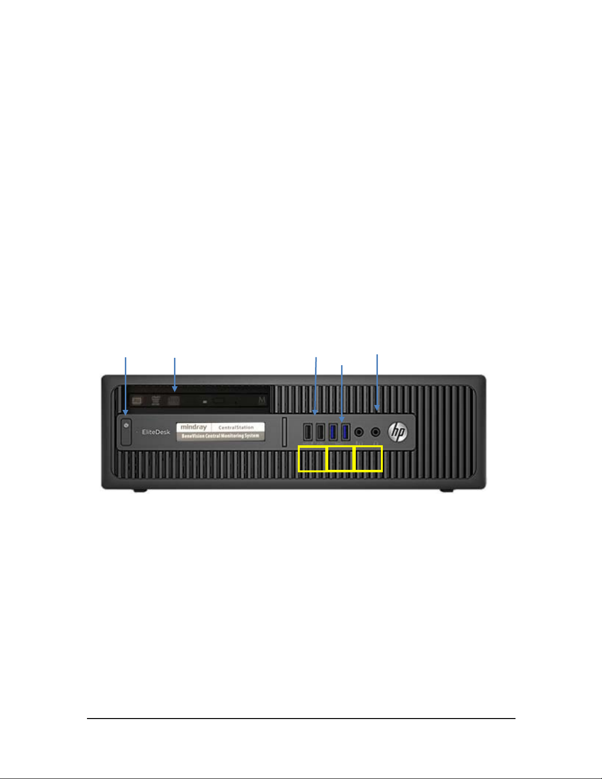
3.2.3 HP EliteDesk 800 G1 SFF (023-000969-00)
Connectors-Front Panel
Power
button
Connectors-Rear Panel
CD/DVD
USB
2.0
USB
3.0
Audio input/output (Not
used)
Mouse/Keybo
ard
Pati
USB
DP
port 1
DP
Port 1
Se
VGA
Displa
USB
USB
Central
Po
Line-in-audio (Not
used)
BeneVision CMS Service Manual 3-7
Page 26
USB
USB
Please be noted that a USB to RS-232 ada pter (PN 023-000739-00) and a RS-232 cab le (PN 300A-10-f08997) are
required to conn ect a pag ing to 800G1 computer.
Description of the Connectors
COM 1: Used for multiple purposes, Programming Transmitters and Recorder.
COM 2: Designated for Paging (Using USB to Serial adapter).
USB 3.0: Used for multiple purposes, Paging, Display 4, Touchscreen, and Mouse/Keyboard.
USB 2.0: Used for multiple purposes, Paging, Touchscreen, Display 4, and Mouse/Keyboard.
Central network: Assigned to the Central Monitoring (Central Monitoring) Netwo rk.
Patient network: Assigned to th e Bedside (Patient) Monitoring Network.
3.2.4 HP EliteDesk 800 G2 SFF (023-001325-00)
Connectors-Front Panel
Power
CD/DVD
Audio input/output (not
Please be noted that a USB to RS-232 ada pter (PN 023-000739-00) and a RS-232 cabl e (PN 300A-10-f08997) are
required to conn ect a pag ing to 800G2 compu ter.
3-8 BeneVision CMS Service Manual
Page 27

Audio
Connectors-Rear Panel
Mouse/Keybo
ard
Serial
(COM
Pat
ien
Line-in-a
udio
Ce
ntr
DP
Port
DP
Port
VGA
Disp
USB
Description of the connectors:
COM 1: Used for multiple purposes, Programming Transmitters and Recorder.
COM 2: Designated for Paging (Using USB to Serial adapter).
Po
US B 3.0 : Used for multiple purposes, Paging, Display 4, Touchscreen, and Mouse/Keyboard.
US B 2.0 : Used for multiple purposes, Paging, Touchscreen, Display 4, and Mouse/Keyboard.
Central network : Assigned to th e Central Monito ring (Central Monitoring) Ne twork.
Patient network : Assigned to the Bedside (Patient) Monitoring Network.
BeneVision CMS Service Manual 3-9
Page 28

Power button Audio USB3.0
Power
LAN1
(Hospital NetWork)
Audio
USB
Keyboard/Mouse
VGA Monitor
RS-232(Recoder/Paging)
DP Monitor2
DP Montor3
LAN2
(Patient NetWork)
USB 3.0
3.2.5 HP EliteDesk 800 G3 SFF (023-001544-00) /HP EliteDesk 800G4
SEF(023-001777-00)Connectors-Front Panel
Please be noted that a USB to RS-232 ada pter (PN 023-000739-00) and a RS-232 cabl e (PN 300A-10-f08997) are
required to conn ect a pag ing to 800G3/800G4 computer.
Connectors-Rear Panel
3-10 BeneVision CMS Service Manual
Page 29
Description of the connectors:
COM 1: Used for multiple purposes, Programming Transmitters and Recorder.
COM 2: Designated for Paging (Using USB to Serial adapter).
US B 3.0 : Used for multiple purposes, Paging, Display 4, Touchscreen, and Mouse/Keyboard.
Central network : Assigned to the Central Monitoring (Central Monitoring) Ne twork.
Patient network : Assigned to the Bedside (Patient) Monitoring Network.
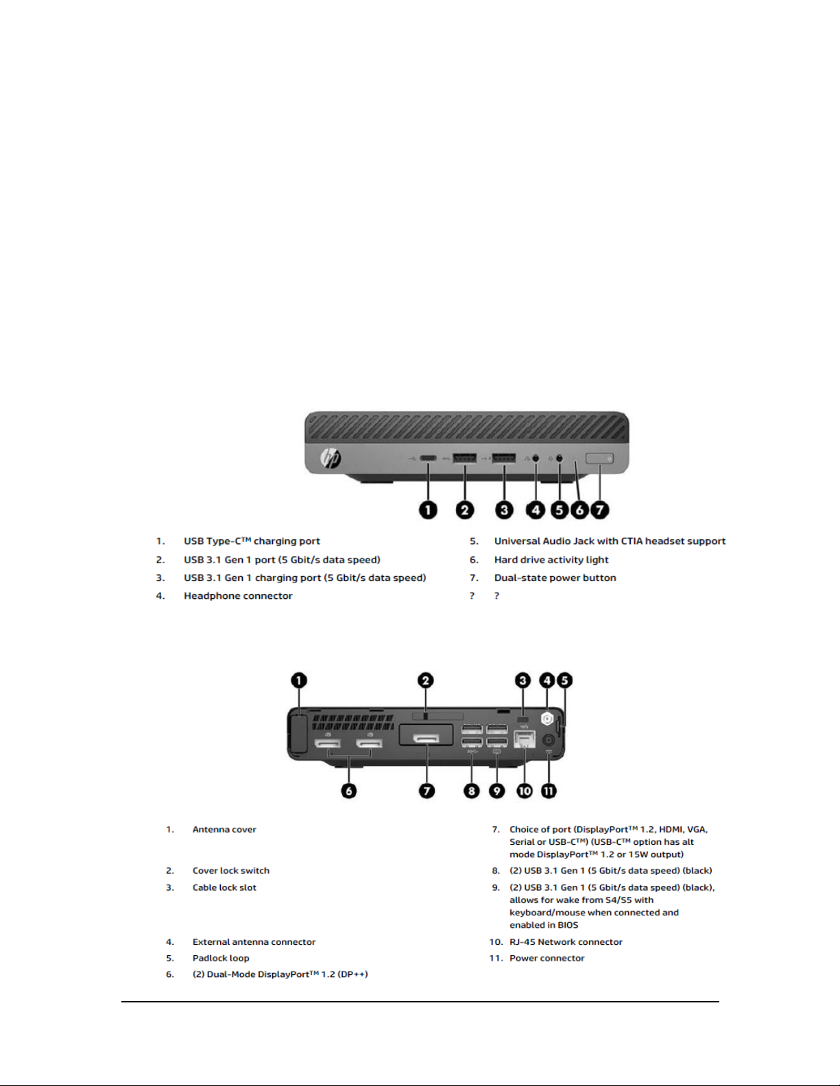
3.2.6 HP ProDesk 600 G3 Desktop Mini (023-001581-00)/ HP ProDesk 600 G4
Desktop Mini (023-001779-00)
Connectors-Front Panel
Connectors-Rear Panel
BeneVision CMS Service Manual 3-11
Page 30

NOTE
3.2.7 Configuring Paging COM Port Settings
To configure Paging COM port settings, follow this procedure:
1. Open the ConfigDir folder in the directory wh ere the CMS so ftware is in stalled: C:\Program Files\Mindray
CMS\CS_MultiBackend\ConfigDir.
2. Open the configuration file named as Paging.ini.
3. Configure the following settings:
Comport=2; // COM Port
baudrate=9600; // Bits per secon d
databit=8; //Data bits
stopbit=1; //Spot bits
parity=N; //Parity
The paging system needs to be physically attatched to the master CentralStation.
3.3 Display Installation
From this section on, the following sections in this chapter describe how to set up all the devices (such as
displays, printer, and recorder) that are go ing to be used with this sy stem and how to con nect them to the
Central Station.
NOTE
If KVM extender s connected to the system, please r efer to Chapter 6 Connection Dia grams
for Host, Remote Display, and KVM.
3-12 BeneVision CMS Service Manual
Page 31

3.3.1 Implementing Double Screen Display by DP-to-VGA Adapter
The double screen display in th e CMS can be achieved by DP-to-VGA adapter:
1. Shut down the computer first.
2. Then connect two screens by DP-to-VGA adapter:
Connect display’s
VGA
Connect display’s
VGA cable
The plug has a spring
Connect DP
port
NOTE
When unplugging the DP-to-V GA adapter, pr ess the spr ing button on the DP plug and then
unplug it downward. Failure to do so may damage the DP plug. T he label beside DP port is
.
BeneVision CMS Service Manual 3-13
Page 32

NOTE
2
3.3.2 Configuring Main Display (Windows 7)
Windows settings will affect CMS settings.
For 19-inch or above display with 4:3 or 5:4 aspect r atio, set its resolution to 1280×1024.
For 21-inch or above widescreen display with 16:9 aspect ratio, set its resolution to
1920×1080.
Use the display in the left most side or in the upper left corner as the main display.
To make the desired screen as main display, fo llow this procedu re:
1. Right click the mouse o n the deskto p, and then select Screen Resolution fro m the pop-up menu to
display the window, as shown in the following figure.
3
2. In the screens displaying list box, select the d esired screen.
3. Select the Make this my main display option.
4. Cl ick the OK button to save the setting and close the window.
3-14 BeneVision CMS Service Manual
Page 33

3.3.3 Aligning the Double Screens (Windows 7)
When the alignment between the screens is ragged, you can align the screens at the same horizontal line or at
the same v ertical line. You can refer the steps below to adjust the multi-screens alignment.
1. Ri ght cl ick the mo use on the desktop, and then select Screen Resolution from the pop-u p menu to
display the window, as shown in the following figure.
2. Click the screen signed with number 1 to select it, and then drag the screen down until the screen signed
with n umber 1 aligns with the screen signed with number 2.
Align dou ble screens at the same horizontal line :
3. Click the OK button to save the setting and close the window.
BeneVision CMS Service Manual 3-15
Page 34

NOTE
2
3.3.4 Configuring Main Display (Windows 10)
Windows settings will affect CMS settings.
For 19-inch or above display with 4:3 or 5:4 aspect r atio, set its resolution to 1280×1024.
For 21-inch or above widescreen display with 16:9 aspect ratio, set its resolution to
1920×1080.
Use the display in the left most side or in the upper left corner as the main display.
To make the desired screen as main display, fo llow this procedu re:
1. Right click the mouse o n the deskto p, and then select Display settings from th e pop-up menu to display
the window, as shown in the following figure.
3
2. In the screens display ing list bo x, select the desired screen.
3. Select the Make this my main display option.
4. Cl ick the OK button to save the setting and close the window.
3-16 BeneVision CMS Service Manual
Page 35

3.3.5 Aligning the Four Screens (Windows 10)
When the alignment between the screens is ragged, you can align the screens at the same horizontal line or at
the same v ertical line. You can refer the steps below to adjust the multi-screens alignment.
1. Right click th e mouse on the desktop, and then select Display settings f rom the pop-up menu to display
the window, as shown in the following figure.
2. Click the screen signed with number 3 to select it, and then drag the screen down until the screen signed
with number 1 aligns with the screen signed with number 3.
Align Four screens at the same horizontal line :
BeneVision CMS Service Manual 3-17
Page 36

3. Click the OK button to save the setting and close the window.
3.3.6 Disabling Audio Enhancement (Windows 7)
1. Open the Control Panel, and then select Hardware and Sound.
2. Select Sound. The Sound window will display.
3. In the Playback tab, select the operating system speaker and then right click the mo use.
4. In the pop-up menu, select Properties.
5. In the pop-up Speaker Pro perties window, select the Enhancements tab.
6. Select Disable all enhancements, shown as below.
3-18 BeneVision CMS Service Manual
Page 37

7. Click OK.
3.3.7 Disabling Audio Enhancement (Windows 10)
3. Open Control Panel, and then select Sound.
4. In the Playback tab, select the operating sy stem speaker an d then righ t click the mouse.
5. In the pop-up menu , select Properties.
6. In the pop-up Speaker Proper ties window, select the Enhancements tab.
7. Select Disable all effects, shown as below.
BeneVision CMS Service Manual 3-19
Page 38

7. Click OK.
3.3.8 Disabling Hot Keys
To avoid th e misoperatio n, you can disable hot key s. There are two ways to disable the hot k eys.
3.3.8.1 Disabling All Hot Keys
Follow this procedure to disable all hot keys.
1. Right click on the Desktop.
2. Select Graphics Options.
3. Select Hot Keys.
4. Select Disable.
3-20 BeneVision CMS Service Manual
Page 39

2
3
3.3.8.2 Disabling Desired Hot Keys
Follow this procedure to disable desired hot keys:
1. Right click on the Desktop.
2. Select Graphics Properties.
3. Enter the Intel ® HD Graphics Control Panel window, and then click the Options button to display the
Hot Key Manager window, as shown in the following figure.
3. In the Enable Hot Keys field, select the Off option.
4. Select the Apply option to apply the setting. The message “The new settings h ave been applied. Do you
want to keep these settings?” displays.
5. Select the Yes button to apply the setting.
6. Cl ick the
BeneVision CMS Service Manual 3-21
icon to close the window.
Page 40

3.3.9 Configuring System Windows Region and Language (Windows 7)
If the langu age used by the current operating system is the same language the user wants to display on the
CMS, it is un necessary to set the regio n and lan guage for the o perating system. In this case, skip this step.
If the langu age of the operatin g system is English but the user requires a non-Engl ish interface for the CMS, it is
necessary to set the region and language of the operating system.
To set th e region an d language, follow this procedure:
1. Enter the Windows desktop and select Star t → Control Panel → Clock, Language, and Region to enter
the Clock , Language, and Region window.
2. Select the Region and Language option to display the Region and Language window.
3. Select the Format tab, and then select the desired language (locale) from the Format drop-down list.
4. Select the Location tab, and then select the desired language (locale) from th e Curr ent locatio n
drop-down list.
5. Select the Administr ative tab, and then click the Change system locale… button to display the Region
and Language Settings window.
6. Select the desired lan guage (locale) fro m the Curr ent system locale drop-down list.
7. Restart the computer to apply the setting.
3.3.10 Configuring System Windows Region and Language (Windows
10/Windows server 2016)
If the langu age used by the current operating system is the same language the user wants to display on the
CMS, it is un necessary to set the regio n and lan guage for the o perating system. In this case, skip this step.
If the langu age of the operatin g system is English but the user requires a non-Engl ish interface for the CMS, it is
necessary to set the region and language of the operating system.
To set th e region an d language, follow this procedure:
1. Enter the Windows desktop and select Control Panel → Region to enter the Region window.
2. Select the Formats tab, and then select the desired language (locale) from the Format drop-down list.
3. Select the Location tab, and then select the desired language (locale) from the Home location
drop-down list.
4. Select the Administrative tab, and then click the Change system locale… butto n to display the Region
Settings window.
5. Select the desired lan guage (locale) fro m the Cur rent system locale drop-down list.
6. Restart the computer to apply the setting.
3-22 BeneVision CMS Service Manual
Page 41

3.3.11 Configuring Windows System Operating Time
1. Enter the Windows desktop and select Control Panel → Date and Time to display the Date and Time
window.
The current tab displays the Date and Time tab.
2. Click the Change time zone… bu tton to display the Time Zone Setting s window.
3. Select the Automatically adjust clock for Daylight Saving Time option.
4. Click the Internet Time tab.
5. Click the Change settings… button to display th e Inter net T ime Settings window.
6. Un select the Synchronize with an Intern et time server option.
7. Restart the computer to apply the setting.
3.3.12 US B Dongle Compatibility
The upgraded BeneVision CMS software is compatible with the BeneVision do ngle. However, some newly
added functions may be disabled.
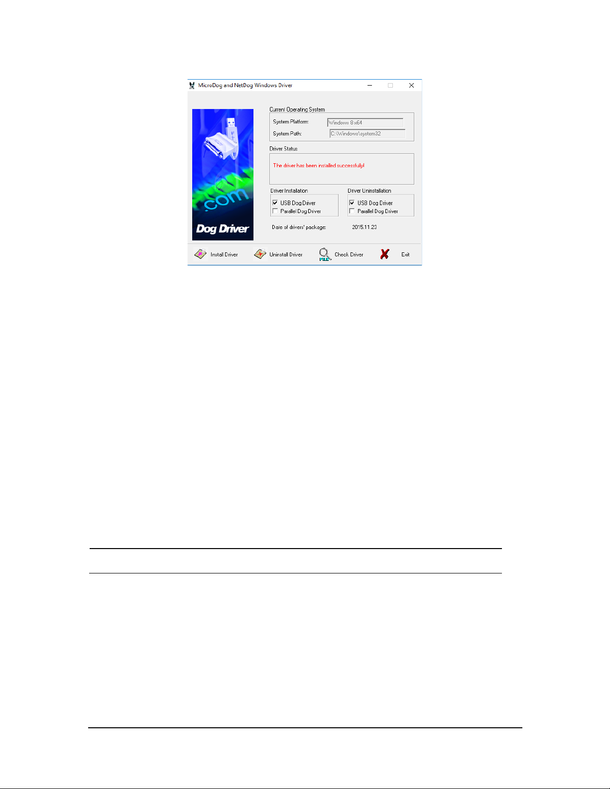
3.3.13 Installing the Micro Dog Driver
1. Click and open the f older titled “USB Dog Driver”. Open the subfo lders and double click on the
“MicroDogInstdrv” application. The application installs the driver for the license dongle.
2. When the Micro Dog Driver installation window opens, select USB Dog Dr iver under Driver Installation.
Finally click the Install Driver button on the lower left hand side of the window.
3. When installation is complete, look for th e message in red “The driver has been installed successfully”.
Click Exit to exit from installation of the Micro Dog Driver.
BeneVision CMS Service Manual 3-23
Page 42
NOTE
3.3.14 Installing/Updating OS Patches(Windows 7)
You need to install the OS patches after installing the Operating System or when you find that the operating
system needs to be updated.
To install or update OS patches:
1. In sert the BeneVision CMS OS Patches CD (PN: 115-034050-00) into your computer and copy the “WIN7
English hotfix” folder to the desk top.
2. Open the “WIN7 English hotfix” folder on the desktop and run the “install all.bat” file.
The OS patches will be installed automatically. Upon completion of installation, the installation window
will be closed automatically.
3. Delete the “WIN7 English hotfix” fo lder from the desktop.
4. Eject the BeneVision CMS OS Patches CD and keep it properly.
Do not shut down your computer until the installation window is closed.
3-24 BeneVision CMS Service Manual
Page 43

3.3.15 Installing/Updating OS Patches (Windows 10/Windows Server 2016)
You need to install the OS patches after installing the Operating System or when you find that the operating
system needs to be updated.
To install or update OS patches:
1. In sert the BeneVision USB stick into your computer.
2. Copy the OS patches (PN: 110-006072-00 or 110-006073-00) into your computer and copy the “WIN10
hotfix” or “WIN2016 hotfix” folder to the desk top.
3. Run the “windows10-kbxxxxxxx-x64.msu” or “windo ws 2016-kbxxxxxxx-x64.msu”
4. In the pop-up Windows Update Standalone Installer dialog, select Yes.
The OS patches will be installed automatically.
5. Upon completion of installation, select Restart Now.
BeneVision CMS Service Manual 3-25
Page 44

NOTE
Do not shut down your computer until the installation window is closed.
3.3.16 Installing the CMS System Software (Running As Application)
NOTE
The softwar e version o f the License and USB dongle must match the version of CMS.
Connect the network cable. The independent network adapter needs to connect to network .
Refer to 3.4 IP Address Setup and Network Connection.
for additional info rmation of independent network adapter.
1. In the CMS software CD, double click “Setup.exe” un der the “Setup” directory to en ter the following
window.
3-26 BeneVision CMS Service Manual
Page 45

NOTE
The language selected as shown in the figure above is the one for display on the screen
during the process of installation but not the default one when the CMS is operating. The
language used when the CMS is operating is to be set up in the following steps.
Set OS language to English before installing CMS system software in English or other
language operating system. Change to the desired OS language after the installation.
2. When the welcome screen displays, click Next.
3. Choose Install Location, and then click Next.
BeneVision CMS Service Manual 3-27
Page 46
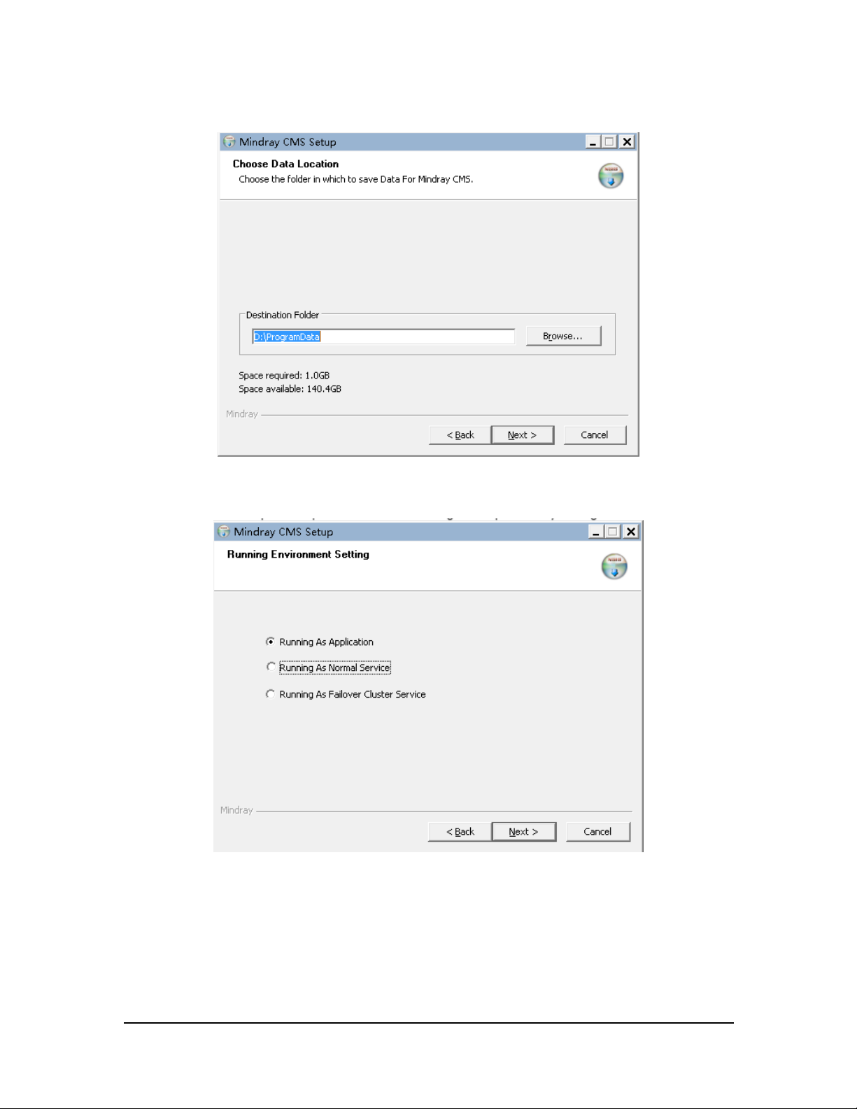
4. Choose Data Location and then click Next.
5. In the Running Environment Setting screen, select Running As Application.
6. When the welcome screen displays, click Next.
3-28 BeneVision CMS Service Manual
Page 47
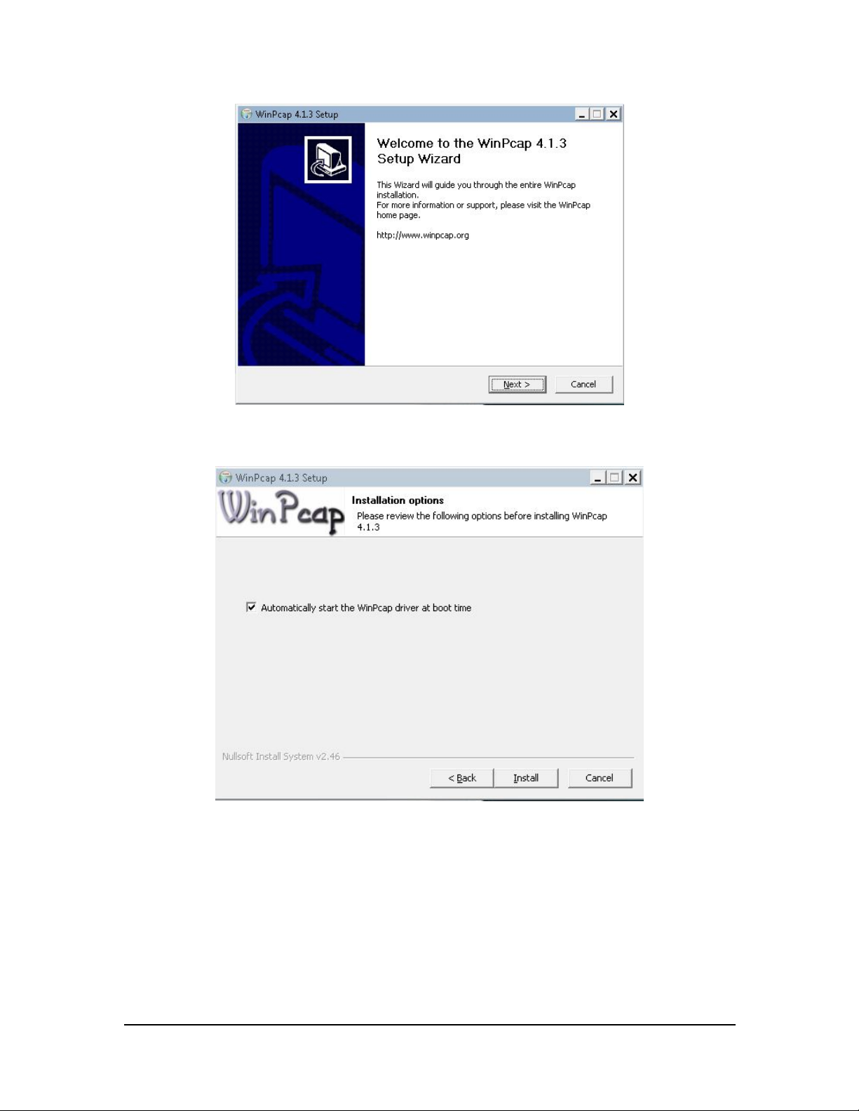
7. Select Automatically start the winpcap driver at boot time, and then click Next.
8. Select Finish, and then restart the computer. The CMS will run automatically.
BeneVision CMS Service Manual 3-29
Page 48

3.3.17 Installing the CMS System Software (Running As Normal Service)
1. Enter the Running Environment Setting screen. For how to enter this screen, see section 3.3.16 Installing
the CMS System Softwa re (Runn ing As Applica tion).
2. In the Running Environment Setting screen, select Running As Normal Service or Running As Failover
Cluster Service. The following procedures take Running As Normal Service as an ex ample.
3. Select Next.
4. Select the proper privileges for services. The following figure serves as an example only.
3-30 BeneVision CMS Service Manual
Page 49

The descending order of privi leges is Syst em, Local Serv ice, Netw ork Se rvice, and User
Defined.
If User Defined is selected, the system will automatically create a system user
dependi ng on the user name and password entered.
5. Import a license.
A valid license dongle or a license file is required for starting a service. If a license file is
available, click the
icon (license tool PN: 110-005825-00). The License dialog is
displayed. In this dialog, select Import and then select the path where the license file is
located.
6. After importing the license successfully, restart th e system.
BeneVision CMS Service Manual 3-31
Page 50

3.3.17.1 Configuring the Network Tab
1. Click the desktop shortcut . The configuration tool screen is displayed.
2. Enter the login password. The defa ult passw ord is 888888.
3. Select the Network tab and the nconfigure network items. The items marked in red rectangle must be
configured. IP addresses in the figure beloware for reference only.
4. Restart the CMS.
5. Admit monitoring devices as below: Select the Device Management tab. Select the “+” button besides
the desired monitoring device.
3-32 BeneVision CMS Service Manual
Page 51

NOTE
6. Conf igure oth er items if needed.
NOTE
Upon completion ofsuccessful network setup, you can access the configuration tool screen
via the WorkStation connected to the Centr alStation. At the Work Station, select the
system menu area in the upper left corner of the screen- select System Setup-select the
Network tab-select the Centr al Station Connection tab-select the desired
Centr alStation-select the Setup button.
3.3.18 Database Update (Optional)
3.3.18.1 Preparation before Updating CentralStation Database
After the CMS is installed, the database needs to be updated.
The MYSQL database in the CMS (Version 02.XX) can be imported into the newly installed
CMS (V ersio n 03.XX)..
The CentralStation ( Version 02.XX and lower) is named as the old CentralStation throughout
this manual.
The CentralStation ( Version 03.XX and above is named as the new CentralStation
throughout this manual.
Database and configurations of the new CentralStation are not compatible with that of the old CentralStation.
Therefore, we provide a special conversion tool to convert the configurations and patient data of old
CentralStation into the format which can be recognized by the new CentralStation.
BeneVision CMS Service Manual 3-33
Page 52

If the database of the old CentralStation is small, for example, less than 100G, or patient h istory data is not
required any more, only configurations need to be converted. The conversion process can be completed in Disk
D directly. Otherwise, a mobile hard disk drive (500GB or above) is required.
3-34 BeneVision CMS Service Manual
Page 53

To convert database and configurations, follow this procedure:
1. Uninstall the old CMS software.
2. Install the database conversion to ol.
3. If the database to be converted is large, prepare a mobile hard disk drive and change the data storage
path to the path where the hard disk drive is located. If the database to be con verted is small, skip this
step.
4. Run th e database conversion tool to convert patient history data and configurations.
5. Uninstall MySQL application and back u p d at a.
6. Copy the entire DB directory in the mobile hard disk drive to Disk D and delete the database path change
configuration file. The configuration file after conversion will be copied to the path of configuration file.
7. Install the new CMS sof tware and check that all the configurations are correct.
3.3.18.2 Judging Disk Space and Preparing A Mobile Hard Disk Drive
Double disk space is requ ired for database con version. If the database o f the old CMS has occupied mo re than
100G of Di sk D, usu ally an ex tra mobile hard disk drive should be available for storing data that is converted.
The remaining disk space of the mo bile hard disk sh ould be at least greater than the occupied space of current
Disk D.
Please create the CMSConfig.ini file in the root directory of Disk C and add contents to the file as shown in the
following command.
[DataServer]
StorePath=N:\\
NOTE
The command above is an example only. In the command above, N repr esents the actual
disk of the mobile hard disk drive.
Under these conditions:
The occupied space of Disk D is small.
Although the o ccupied s pace of Disk D exceeds 100GB, customers do not need to convert all the patient
history data. They o nly need to con vert data of a few patient.
A mobile hard disk drive is not requ ired and the CMSConfig.ini file does not need to be edited either.
BeneVision CMS Service Manual 3-35
Page 54

3.3.18.3 Running Conversion Application
Run the database conversion tool (PN: 110-005553-00) installation application and complete installation as
prompted.
After running the database conversion tool, the following screen is displayed.
The menu items in the figure above are described belo w:
1. Items under Patient List:
In the Select column: select the discharged patient who se data needs to be converted. The
conversion speed improves when a f ewer patients are selected.
In the State column: Ready indicates that conversion is no t started. Transforming indicates that
data conversion is in progress. Complete indicates that data con version is completed.
In the ID column: database ID is displayed and is for ref erence only.
In the BedNo column: the bed n umber corresponding to patients being monitored is displayed.
In the Name column: patient name is displayed.
In the MedicalNo column: patient ID is displayed.
In the Online column:1 indicates that the patient is not discharged y et. 0 indicates that the patient is
discharged.
In the Discharged Time column: patient discharge time is displayed.
3-36 BeneVision CMS Service Manual
Page 55

2. Patient info rmation being converted and the progress o f data conversion are displayed under Transform
Information.
3. Selecting Config Transform starts converting configu rations such as n etwork setup and telemetry setup.
4. In the Data Transform box , select the data to be converted. If you select Wave, it may take several hours
to complete conversio n.
5. Selecting Data Transform starts converting patient history data.
After opening the database and configuration conversion tool, follow this procedure:
1. Select the data of patients to be converted against the patient info under Patient List.
2. In the Data Transform bo x, s elect the data to be converted.
3. Select Config Transform to convert configurations
4. Select Data Transform to convert patient h istory data. Depending on the number of patients and the
data size, this step may take a relatively lon g time. You can see the conversion progress in the Transform
Information box.
3.3.19 Confirming Configurations and Data
Upon completion of conversion, close the conversion application. Uninstall the database conversion tool and
delete the C:\ CMSConfig.ini file. Then install the new version of CMS software. After completion of installation,
add contents to D:\ProgramData\Mindray\CMS\CMSConfig.ini by running the following commands.
[DataServer]
StorePath=N:\\
NOTE
The command above is an example only. In the command above, N repr esents the actual
disk of the mobile hard disk drive.
1. Copy configuratio n files after conversion to the sto rage path (D:\ProgramData\Mi ndra y\CMS\) where
configuration files of the new CMS software are located.
2. Replace the existing conf iguration files. The path of configuration files after conversion is DB Update
software installation directory\ConfigServer\Release. The files are named as "current.cfg" and
"current_backup.cfg".
3. Start the new CMS sof tware and verify th at all the conf iguration items are converted pro perly, especially
telemetry-related configurations such as alarm limits, alarm on/off, and alarm priority and CMS
alarm-related settings.
4. Access the discharged patients screen to check that all the patient history data are converted properly. If
all the pieces of inf ormation are correct, select Next. Otherwise, re-convert.
BeneVision CMS Service Manual 3-37
Page 56

NOTE
3.3.20 Operations after Conversion
If bo th configuratio ns and data have been con verted and are verified to be correct, select Exit to Windows
from the Factor y Maintenance menu of the CMS. Then delete the C:\ CMSConfig.ini" file and edit the
D:\ProgramData\Mindray\CMS\CMSConfig.ini file by running the following command.
[DataServer]
StorePath=N:\\
Follow this procedure:
1. Open Control Panel – select Programs- select Uninstall – select Mindray CMS DataBase.
2. Delete the MySQLData file f older under the root directory of Disk D. Please be n oted that it cannot be
just mo ved into the recycle bin. It should be deleted completely. To ensure data security, you can back
up MySQLData to a mobile hard disk drive and then delete the MySQLData file fo lder.
3. Copy the entire DB directory in the mobile hard disk drive to Disk D.
4. Restart the CMS.
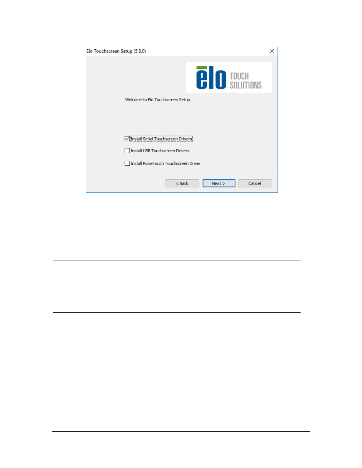
3.3.21 Touchscreen Driver Installation (Optional)
3.3.21.1 Installing Elo Touchscreen Drivers (Via Serial)
All video/touchscreen cables need to be connected to the CMS befor e continuing to next
step.
Serial touchscreen drivers are only installed using the AT EN CE750 and using the USB to
Serial adapters (023-000739-00).
1. Run the file “SW602540_EloMouseTouch_5.8.0 “.
2. Select Unzip.
3-38 BeneVision CMS Service Manual
Page 57

3. Select the des ired langu age, and then click Next >.
4. Select the desired option. The following figure and steps take installing serial touchscreen drivers as an
example.
BeneVision CMS Service Manual 3-39
Page 58
s
5. In the License Agreement screen, select Ye s.
6. Select Auto-detect Elo Touchscr eens, and then click Next>.
7. Select the proper COM ports, shown in the following screen, and then click Next>.
NOTE
The COM3 is not intended for touchscreen connection for the Kontron KISS 2U and HP
800G1/800G2/800G3/800G4 computers.
By default, the COM1 port is for recorder connection and programming telemetr y devices,
and the COM2 por t for paging system. Never configure touchscreen devices to COM1, CO M2,
and COM3.
3-40 BeneVision CMS Service Manual
Page 59
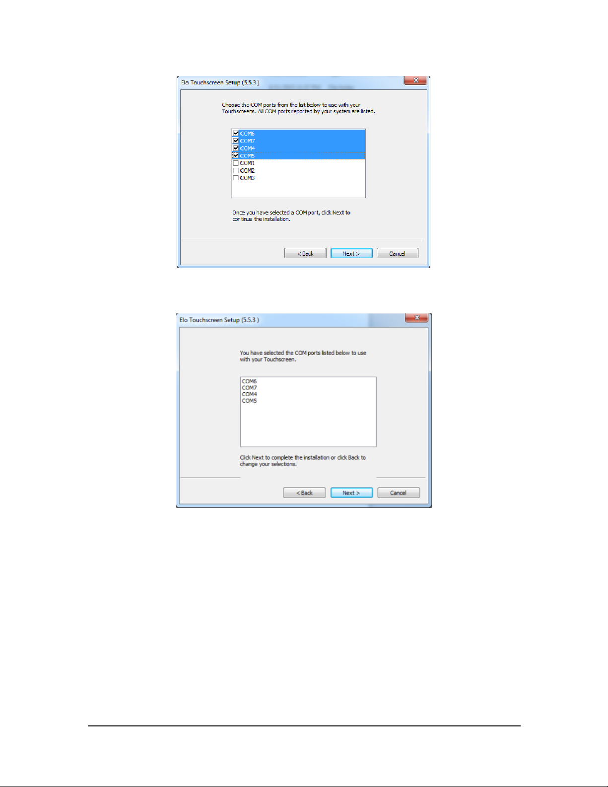
7. The COM ports list displays, shown in the following screen. Click Next>.
8. Select Calibrate Elo Touchscreen monitors, and then click Finish.
9. Calibrate the touchscreen according to the screen prompts.
BeneVision CMS Service Manual 3-41
Page 60

3.3.21.2 Installing EloTouchscreen Driver via USB Port
NOTE
All video/touchscreen cables need to be connected to the CMS before continuing to next
step.
1. Insert the Elo touchscreen driver CD and run the file “Setup.exe”.
2. Select the desired language, and then click Next >.
3. Select th e desired option. The following figure and steps take installing U SB touchscreen drivers as an
example.
4. In the License Agreement screen, select Yes .
5. Select Calibrate Elo Touchscreen monitors, and then click Finish.
6. Calibrate the to uchscreen according to the screen prompts.
3.3.21.3 Installing HP Touchscreen Driver via USB Port
No USB touchscreen driver is needed. Touchscreen can function directly after system is installed.
To calibrate the to uchscreen, follo w this procedu re:
1. Enter the Windows desktop and select Star t → Control Panel → Tablet PC settings to enter th e Tablet
PC settings window.
2. Select Setup.
3. Calibrate the touchscreen according to the screen pro mpts.
3-42 BeneVision CMS Service Manual
Page 61
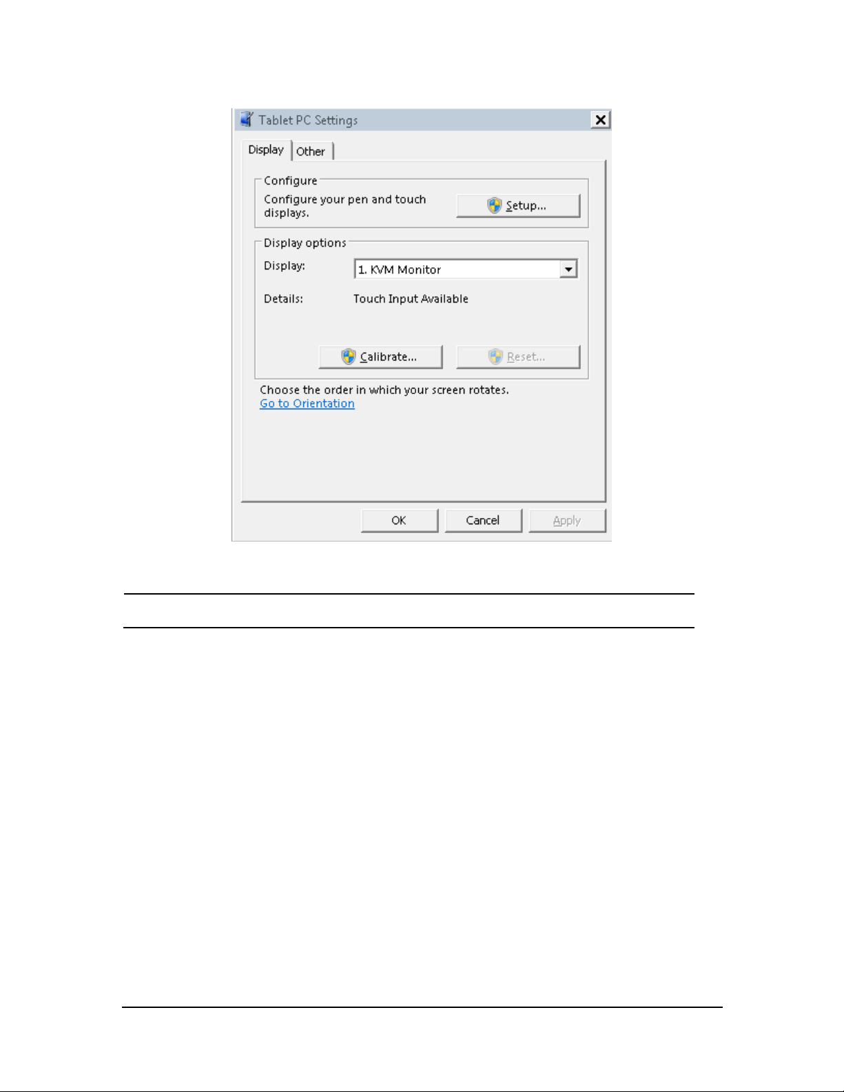
NOTE
Touchscreen via usb port of the CMS host,.
3.3.22 Disabling Display Menus (Optional)
3.3.22.1 Locking Display and Power Buttons on Elo Display
To lock the display buttons : press and hold the Up arrow & Menu button simulatenously for 10 secon ds.
To lock the power button: press and hold the Up arrow & power button for 10 seconds.
3.3.22.2 Locking Display and Power Buttons on HP Display
To lock the display buttons : press and hold the Menu button for 10 seconds.
To lock the power button: press and hold the power button for 10 seconds.
BeneVision CMS Service Manual 3-43
Page 62
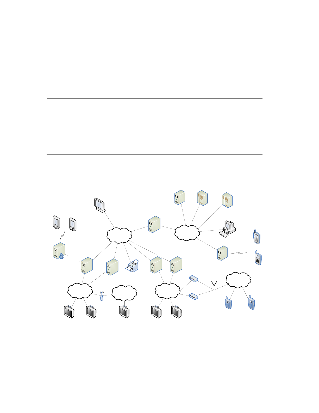
Serial
Interface
Hospital
Network
Central Network
(Hospital Supplied
VLAN)
Monitor Network
Subnet 2
CS 1
CS 1 CS N
CS N
Monitor 1 Monitor N Monitor 1 Monitor N
e
-Gateway
EMR/CIS/
HIS, etc
ADT Server
….
….
….….
Wi-Fi
Access
Points
Wireless Monitor
SSID 1
Monitor Network
Subnet 1
WS/
VS
12lead ECG
Mgmt
Telepack 1
Wireless
Receiver 1
Antenna Array
Telepack N
608MHz
Band
Wireless
Receiver N
Alarm
Paging
System
Pager
Pager
MobileServer
CMSViewer
MobileViewer
MobileViewer
3.4 IP Address Setup and Network Connection
The PC will be equipped with two network adapters to isolate the monitor LAN and the ex ternal network to
ensure network bandwidth and data safety for the monitors.
NOTE
If two network adapters are used, be sure to identify which is for monitor network and
which is for external network connecting multiple CMS or other information systems.
Correctly set IP address for each networ k adapter.
If two network adapters are used, connect them to cor responding networks as desir ed.
Do not connect both network adapter s to the same network segment, e.g., do not connect
them to the monitor network at same time.
3.4.1 Network Connection Using Multiple Network Adapters
The figure below sho ws the network connection using multiple network adapter.s
As shown in the figure, the two network adapters are respectively connected to th e monitor LAN and the
external network. A printer can be connected to any monitor network. Connecting a printer to Monitor
Network Subnet 2 is for illustration only.
3-44 BeneVision CMS Service Manual
Page 63

Each Wired Su bnet shou ld meet the followin g network requirements:
96 Broadcast devices per subnet
400 Multicast devices per subnet
B roa dcas t and Multica st devices ca nno t co-ex ist in the same Patient Mo nitoring su bnet.
One TM S receiver is equivalent to 1 B roadcast device and can co-exist in th e same subnet as Multicast
devices.
U p to 96 Bro adcast a nd M ulticas t dev ices can co-exist in the Central Monitoring subnet.
U p to 400 devices can co-exist in the same subnet as B roadcast or M ulticast devices
Communication Mode Device
Broadcast Only DPM 3/4/5/6/7, Passport V, TMS -6016
Multicast or Broadcast Passport 8/12, Passport 8/12, Accutorr 7, T1,
DPM6+, DPM7+, TMS-6016
ELAN Passport 2, Spectrum, Spectrum OR, V-Series,
Telepack-608
Wireless Network Requirements:
A separate antenna array can support at most 188 TD60 an d TEL-100/200
3.4.1.1 Supported Monitoring Device
Bedside Monitors
Passport 12m/17m Passport 8/12 Accut orr 7
T1 DPM 3/4/5/6/7 V 12/21
Spectru m Spectrum OR Passport 2
Passport V
Ben eVision N12/N17/N19/N22/N1
Telemetry
TMS-6016 (Tel-100/200) TMS60 (TD 60) Telepack-608
TM80 (2.4gGHz/5.0GHz)
BeneVision CMS Service Manual 3-45
Page 64

NOTE
3.4.2 Patient Network
Patient network is required for:
Patient monitors
Receiver cabinets
Printers
If two network adapters are used, the one (hereinafter called integrated network adapter)
integrated on the PC main board is normally connected to the monitor network and the one
(her einafter called independent networ k adapter ) installed in the PCI slot is connected to
the external network.
The default networ k adapter is the integrated network adapter, which is u sed for the
patient network using CMS+ pr otocol only.
For CMS+ protocol, use IP address scheme 172.16.0.X and subnet mask 255.255.0.0.
Every IP Address on each individual network has to be unique. Duplicate IP Addr esses will
cause networ k connection failures.
The hospitals can set their own desired DHCP or IP addresses. However , the CMS IP address
must not be changed.
To set th e IP addresses of the in tegrated network adapter:
1. Select the
and Shar ing Center.
icon at the bottom of the screen to enter the following screen. Then click O pen Networ k
3-46 BeneVision CMS Service Manual
Page 65

2. In the pop-up screen, select Change adapter settings.
3. After accessing the Network Conn ection screen, right click Local Area Connection.
4. In the Local Area Connection Properties screen, double click Internet Protocol version 4 (TCN/IPv4) and
then select Properties.
BeneVision CMS Service Manual 3-47
Page 66

5. In the Internet Pr otocol V ersio n 4 (TCP/IPv4) Proper ties screen, enter the patient netwo rk IP address
172.16.0.X and th e subnet mask of 255.255.0.0. Th en cli ck OK. The following figure is for reference only.
9. Click OK to finish setting IP address.
3.4.3 Central Network
The independent network adapter is used to connect the extern al network. Its IP address shou ld be configured
acco rding to a ctua l us e.
Central network is required f or:
WorkStation/ViewStation Communication
CMS Viewer
Remote View
Mobile Viewer
eGateway
3-48 BeneVision CMS Service Manual
Page 67

IP Address Setup
To implement Remote View function between CMS, each CMS needs to be equipped with at least two n etwork
adapters, one of which is for internal communication within the current CMS and the other for
inter-communication between the CMS. The typical configuration is shown below:
Curr ent CMS A Tar get CMS B Tar get CMS C
Network adapter
A1
172.16.0.X1 192.168.0.X2 172.16.0.Y1 192.168.0..Y2 172.16.0.Z1 192.168.0..Z2
As shown in the table above, network adapter A1, B1 an d C1 are used for the communication between the
CMS and the monitors. Their IP addresses are in the s ame network segment with the IP addresses of respective
monitors. Network adapter A2, B2 and C2 are used for the in ter-communication between the CMS. Their IP
addresses belong to th e same network segment and X2, Y2 and Z2 shall be different.
See Steps 1 to 5 in 3.4.2 Pa tient Netwo rk to conf igure the IP address and the subnet mask for Local Area
Conn ection 2. Please be noted that the IP address of Local Area Connection 2 sho uld be set to 192.168.0.X a nd
the s ubnet mask sho uld be set to 255.255.0.0.
Network
adapter A2
Network
adapter B1
Network
adapter B2
Network
adapter C1
Network
adapter C2
NOTE
If a CMS needs to implement the Remote View function between CMS, other CMS has to
connect to thecentral network . Please refer to CMS operator’s manual for details.
3.5 Synergy Software Installation (Optional)
Synergy is a software application for sharing a keyboard and mouse between multiple computers.
The installation process includes server and client installation.
BeneVision CMS Service Manual 3-49
Page 68

3.5.1.1 Installing and Configuring a S erver
1. Insert the Ben eVision CMS Tool SW CD (P/N 115-047955-00) into the computer CD drive, and find the
Synergy software application (P/N 110-003997-00) in the CD.
2. Run “synergy1.6.3.exe”.
3. In the welcome screen, click Next.
4. In the End-User License Agreement screen, select I accept the terms in the License Agreement and then
click Next.
5. Always click Next u ntil the installation is complete. The Synergy application automatically starts after the
installation is complete.
6. In the following screen, select the proper language and then click Next.
7. Select Server (share this computer’s mouse and keyboard), and then click Finish.
3-50 BeneVision CMS Service Manual
Page 69

8. In the following screen, when the window prompting “Do you want to enable auto config and install
Bonjour? This feature helps you establish the connection” is displayed, select No.
9. Select Config ure Server ….By default, server (share this computer’s mouse and keyboard) and Configure
interactively are selected.
BeneVision CMS Service Manual 3-51
Page 70

NOTE
10. In the Screens and links tab of Server Configuration, drag the computer icon o n the upper left corner o f
screen to a proper position in the grid. Then an unnamed icon appears in the grid, as shown below.
The actual computers should be placed in accor dance with the position in the grid.
11. Dou ble click the computer icon, the Screen Settings screen displays. Enter the computer name in the
field of Screen name according to the client computer name, and then click OK.
3-52 BeneVision CMS Service Manual
Page 71

NOTE
Each computer needs to have a unique name.
12. In the following screen, click Start.
BeneVision CMS Service Manual 3-53
Page 72

3.5.1.2 Installing a Client
1. Fo llow Steps 1 to 6 in the section 3.5.1.1 Insta lling and Con figuring a Server.
2. Select Client (share this computer’s mouse and keyboard), and then click Finish.
3. In the following screen, when the window prompting “Do you want to enable auto config and install
Bonjour? This feature helps you establish the connection” is displayed, select No.
4. Select Configure Server…..By defau lt, Client (use another computer’s mouse and keybo ard) is selected.
5. Enter the server IP.
6. Click Apply.
3-54 BeneVision CMS Service Manual
Page 73

3.6 Installing Printers
3.6.1 Supported Printers
The CMS supports the following printers:
HP LaserJet M401n
HP L aserJet M602
HP L aserJet M605n
HP LaserJet M608
3.6.2 Printer Installation Procedures
The installation of H P La serJet M602 is used as an example.
NOTE
Connect a printer to the network before performing the following operations.
BeneVision CMS Service Manual 3-55
Page 74
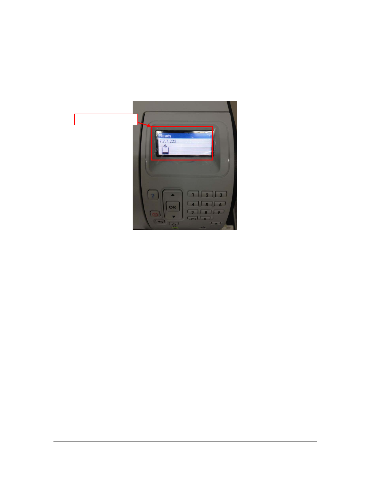
Verifying the Print er I P:
1. Load the printer with paper an d connect with the computer (Set the printer IP addres s to 172.16.0.X).
2. Power on the printer. The printer IP address information will be shown on the screen of the control panel
as below:
The prin ter IP
3. Verify this IP address is in the same network segment as the patient network. If not, add a new computer
TCP/IP address so that it is in the same network segment with the printer IP address.
Adding TCP/IP
For how to add TCP/IP, refer to section 3.4.2 Patient Network.
Installing the network printer
1. In sert the printer driver CD into the CD-ROM.
2. Open Control Panel.
3. Select Devices an d Printers.
4. Right click on anywhere on the Devices and Printers page and then select Add a Printer .
5. Select Add a network, wireless or B luetooth printer an d then click Next.
3-56 BeneVision CMS Service Manual
Page 75
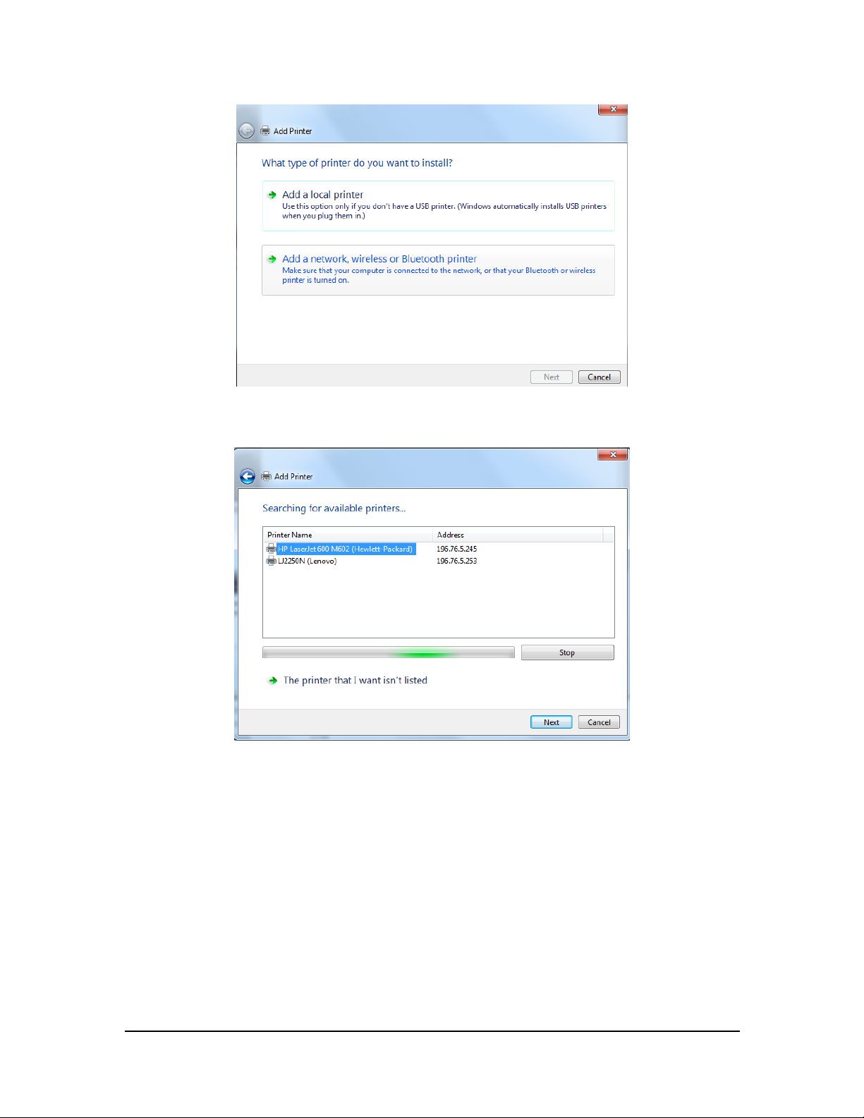
6. Select the desired prin ter, and then click Next.
BeneVision CMS Service Manual 3-57
Page 76

7. Click Have Disk… to select the printer driver which is located in the CD ROM. The following figure is for
reference only.
8. Click Browse to browse to the folder where the CD drive is stored. The following figure is fo r reference
only.
3-58 BeneVision CMS Service Manual
Page 77
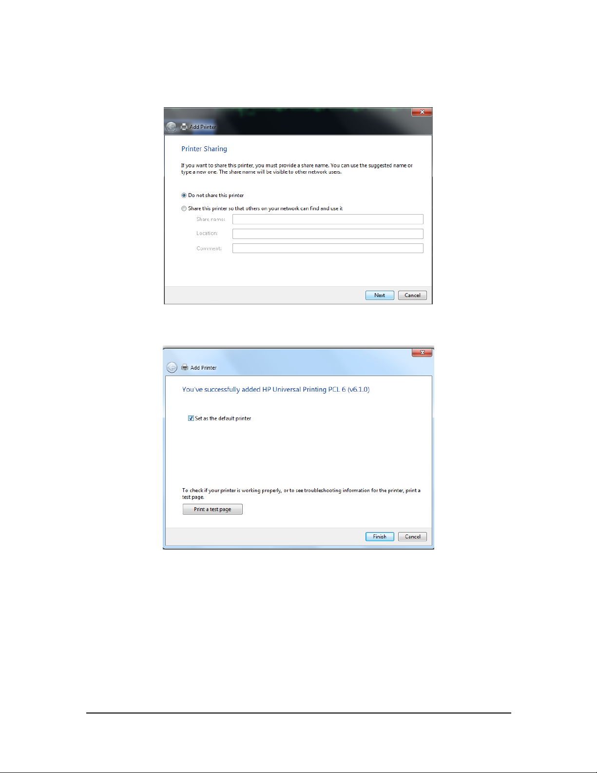
9. Click Next. The printer driver will be installed automatically.
10. Upon completion of installation, click Finish.
If you need to add a second n etwork printer, repeat the steps above.
Configuring the network printer IP on a new printer
When multiple central station s use one printer, if a printer goes bad, you do not need to bring the central
stations down to install the new drivers. You only need to set the IP address on the new printer.
Follow this procedure to set the IP address of a network printer:
BeneVision CMS Service Manual 3-59
Page 78
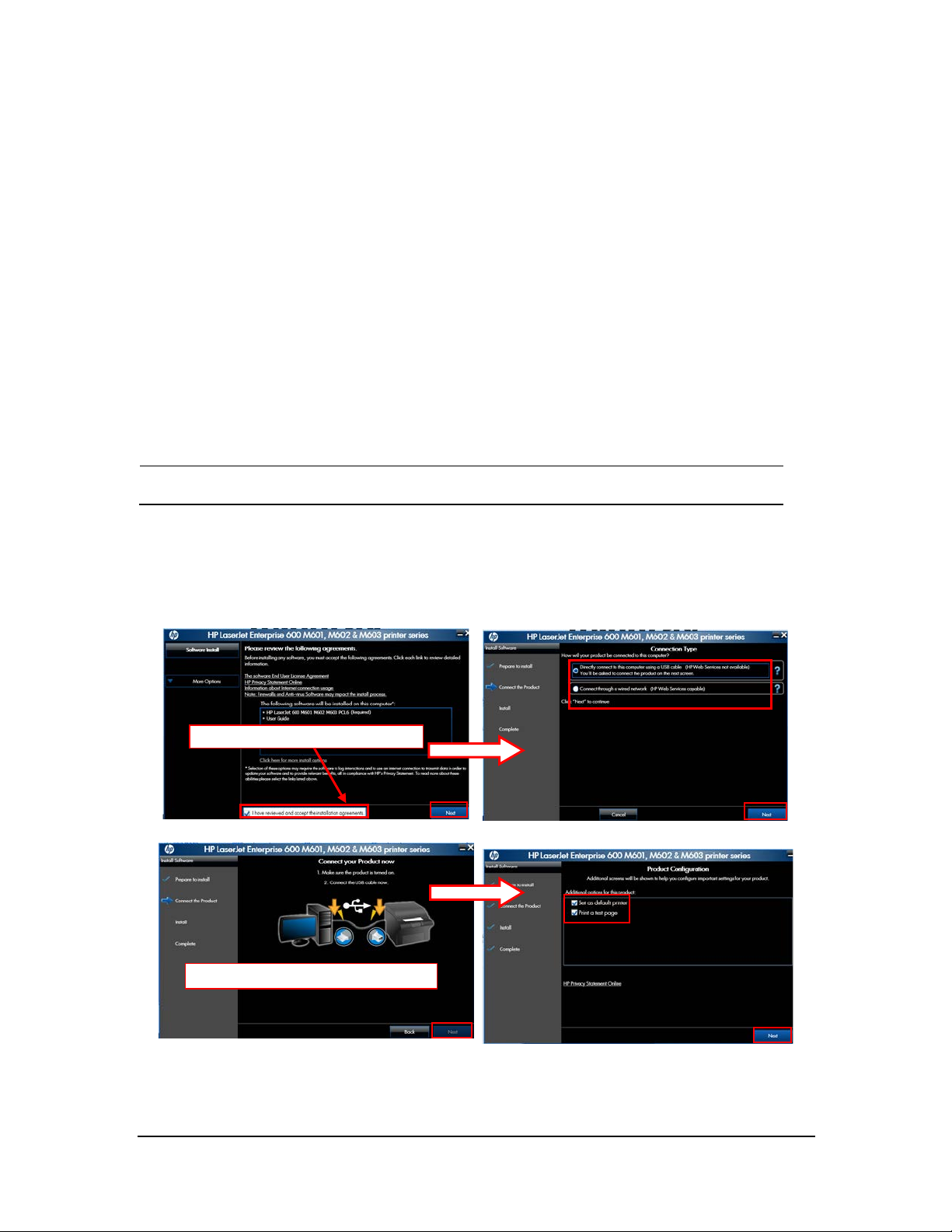
NOTE
Accept the installation agreement.
1. Open Control Panel.
2. Select Devices an d Printers.
3. Ri ght cl ick on the desired printer.
4. Select Printer Properties.
5. In the Printer Properties screen, select Ports and then select Configure Port….
6. Change Printer Name or IP Addr ess to the IP address of the printer being used. For example, 172.16.0.X.
7. Click OK.
Installing the USB printer
Make sur e that the USB cable of the pr inter is not connected with computer .
1. Right click th e mouse to o pen CD driver, and then double click “setup.exe” file in the root directory.
2. Install the driver by following the indications shown below in the order of from left to right and f rom top
to bottom:
When this page shows, connect USB
3-60 BeneVision CMS Service Manual
Page 79
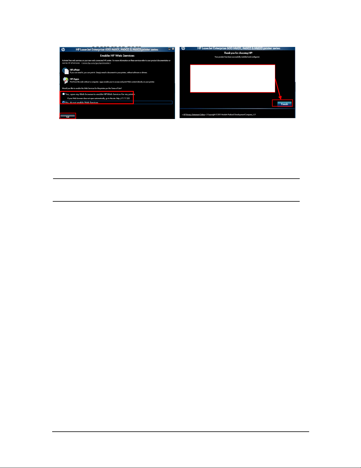
NOTE
When the test page is
successfully printed, please click
this bu tton.
3. After test page is printed, close all the pop-up windows and access “Printers and Faxes” again.
4. Select HP LaserJet 600 M601 M602 M603 PCL6 printer and re-name it as “M602_usb” to complete
installation of printer’s USB driver.
When installing a printer, select to install network driver or USB driver based on the actual
requirement. Connect the printer to the CMS networ k if network printing is needed.
3.6.3 Tasks after Printer Installation
To improve the print effect, follow the steps as below:
1. Enter the Windows desktop and select Start → Control Panel → Hardware and Sound → Devices and
Printers.
2. In the Printer s and Faxes field of the Devices and Printers window, select the desired printer and right
click the pri nter .
3. Select the Printer properties option from the pop-up menu to display the printer properties window.
4. Select the Advanced tab.
5. Un select the Enable advanced printing features option.
6. Click the OK button to apply the setting and close the printer properties window.
BeneVision CMS Service Manual 3-61
Page 80

To block the pop-up functional window when running the CMS, follow the steps as below:
1. After install the printer, implement a printing task.
A prompt window displays at the bottom-right of the desktop, as shown in the following figure.
2. Select the Settings option to display the Settings window, as shown in the followin g f i gur e.
3. Select the Notification tab, and unselect the Enabled: check box .
4. Select the Offers tab, and unselect the Allow special device inf ormation and offers to be displayed check
box.
5. Click the OK button to apply the settings and close the Settings window.
3-62 BeneVision CMS Service Manual
Page 81

3.7 Installing PDF Creator
When repo rts need to be o utput in PDF format, you need to install PDF Creato r on the CMS host.
3.7.1 PDF Creator Installation Procedures
To install the PDF Creator, follow this procedure:
1. Double click PDF Creator.exe in th e customer-provided PDF Creator package (which can be downloaded
from http://www.pdfforge.org or purchased). The following steps take installing PDF Creator 2_4_1-Setup
as an example.
2. Select the setup language and then click OK. Wait for the completion of PDFCreator installation
preparation.
3. Upon completion of installation preparation, click Next on the Welcome screen of PDF Creator Setup
Wizard.
BeneVision CMS Service Manual 3-63
Page 82
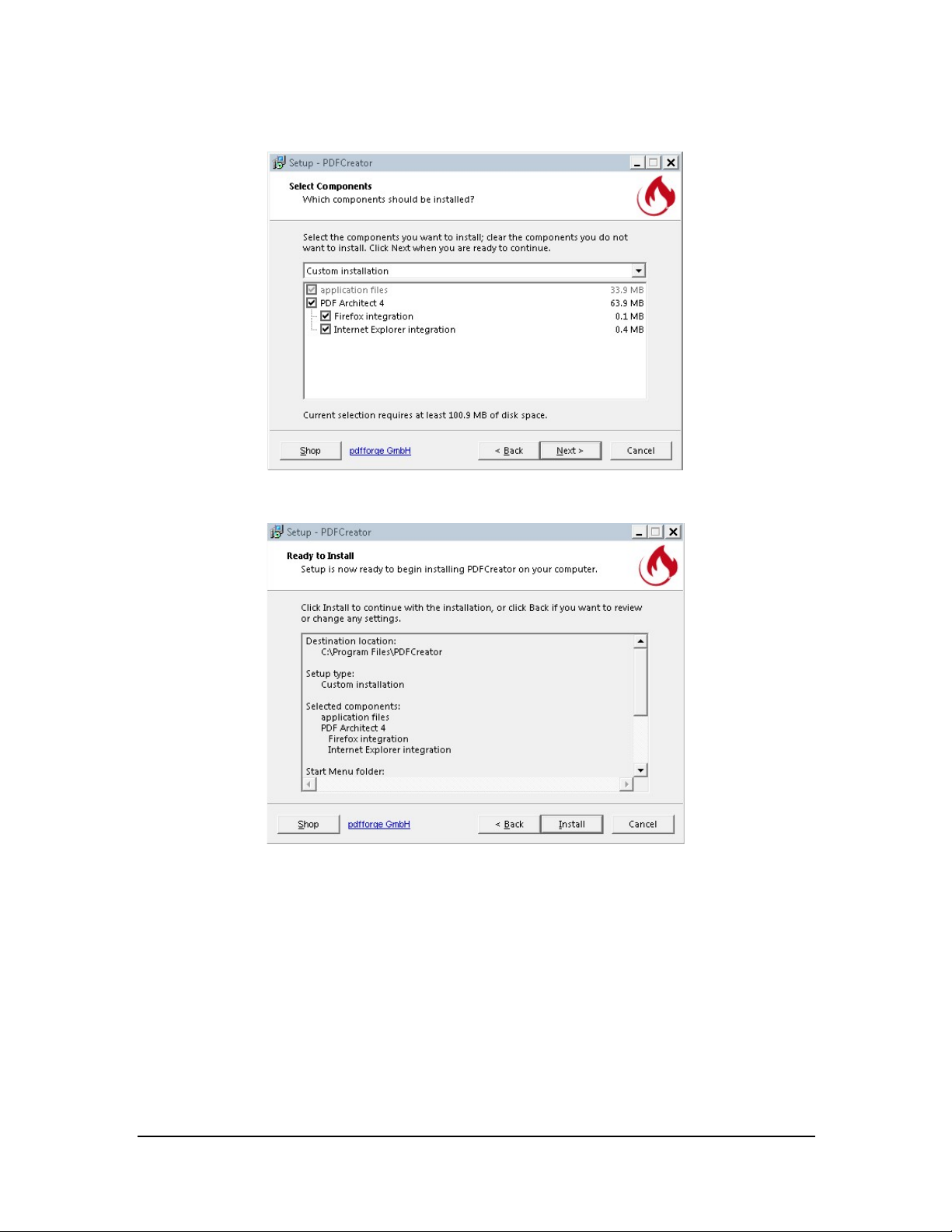
4. In the Select Components screen, use the default settings and then click Next.
5. On the Ready to Install screen, cli ck Install.
3-64 BeneVision CMS Service Manual
Page 83

6. Upon completion of installation, click Finish.
7. Configure pdfcteater.
a. Ope n the PDF Creator and then select Profile Settings to make the desired
configuration changes.
b. Select Actions and Uncheck Open document.
BeneVision CMS Service Manual 3-65
Page 84

c. Select PDF to configure the PDF file properties.
d. Select Security.
e. Select Encrypt PDF documents, se t the Encryption level to Medium, and only allow
the user to print or view the exported PDF.
3-66 BeneVision CMS Service Manual
Page 85

f. Save the profile changes.
g. Sele ct Applications Se ttings.
BeneVision CMS Service Manual 3-67
Page 86

h. Under Update, set Check f or updates to Never.
i. Save the application settings changes.
3-68 BeneVision CMS Service Manual
Page 87
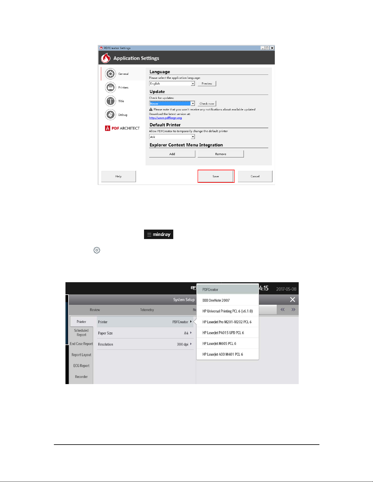
3.7.2 Verifying Installation of PDFCreator at the CMS
To verify installation of PDFCreator at the CMS, follow this procedure:
1. Select the system menu area
2. Select
3. Select the Print tab → enter the required password → select the OK
4. Verify that PDFCreator is displayed in the drop-down list for Pr inter.
System Setup to a ccess t he System Setup menu.
in the upper lef t corner of th e CMS screen.
button → select the Printer tab.
BeneVision CMS Service Manual 3-69
Page 88
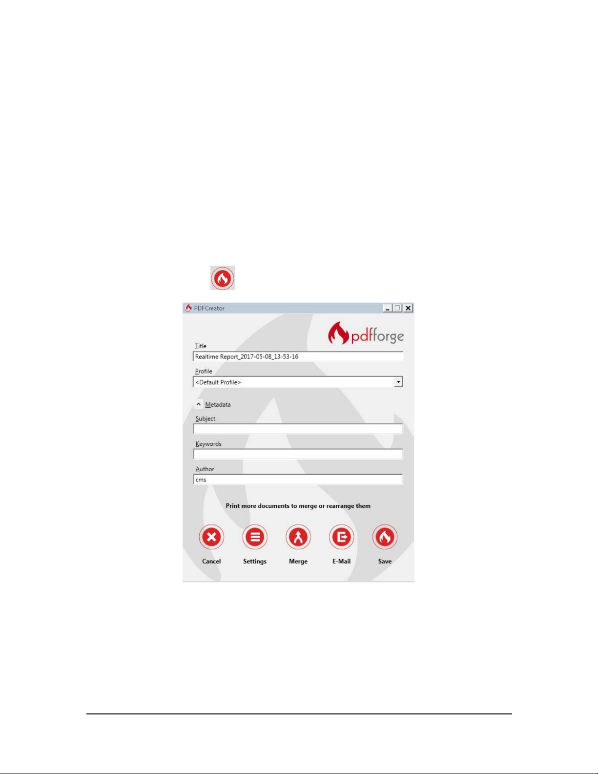
3.7.3 Printing PDF Reports
Yo u ca n print PDF reports manually or set the printer to print PDF reports automatically. For details on printing
PDF reports, see BeneVision Central Mo nitoring System Operato r’s Manual (PN 046-010879-00).
3.7.4 Saving PDF Reports Manually or Automatically
You can save PDF reports manually or automatically.
3.7.4.1 Saving PDF Reports Manually
To save PDF reports manually, follow this procedure:
1. Select the Save button
.
3-70 BeneVision CMS Service Manual
Page 89

2. Select the des ired file save path. Suppose the PDF file save path is E:\REPORT.
3. Access E:\REPORT, and th en you can view the PDF report ou tput.
BeneVision CMS Service Manual 3-71
Page 90
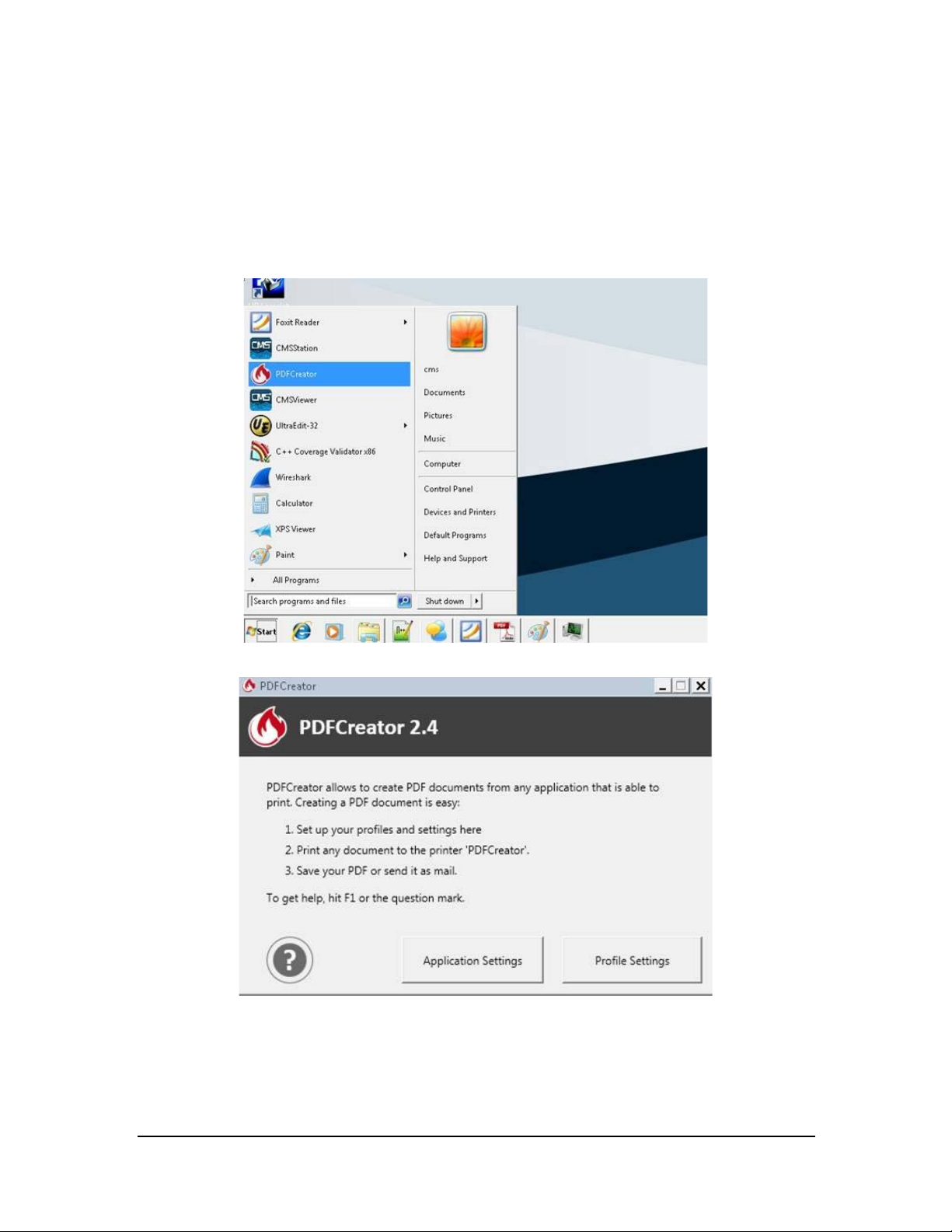
3.7.4.2 Saving PDF Reports Automatically
To save PDF reports automatically, follow this procedure:
1. Upon completion of PDFCreator installation, from the Windows Start menu, select PDFCreator→select
Profile Settings.
3-72 BeneVision CMS Service Manual
Page 91

NOTE
2. In the Profile Settings window, select the Auto-Save section. Check Enable automatic saving and then
select the desired Target Folder. Suppose the target folder is E:\REPORT.
3. Go back to the ViewBed screen and then select the Pr int quick key. This step takes printing a real-time
report as an ex ample.
The prompt “Printing…” is displayed at the CMS. Wait fo r the prompt of “Printing Co mpleted”. Upon
completion of printing, the PDF report will be saved in the target folder automatically.
If you need to print other reports such as EEG report, select corresponding print button. For
how to select the print button, see BeneVision Central Monitor ing System Operator’s
Manual ( PN 046-010876-00).
BeneVision CMS Service Manual 3-73
Page 92

4. Access the target folder (in this example:E:\REPORT ), and then you can view the PDF report output.
3.7.5 Viewing PDF Reports
You need to install a PDF reading application such as PDF Reader, Adobe Acrobat , or Fox it to view PDF reports.
To view PDF repo rts, open the PDF report in the target folder using the desired PDF reading application.
The PDF report opened via an Adobe application is as shown below.
3-74 BeneVision CMS Service Manual
Page 93
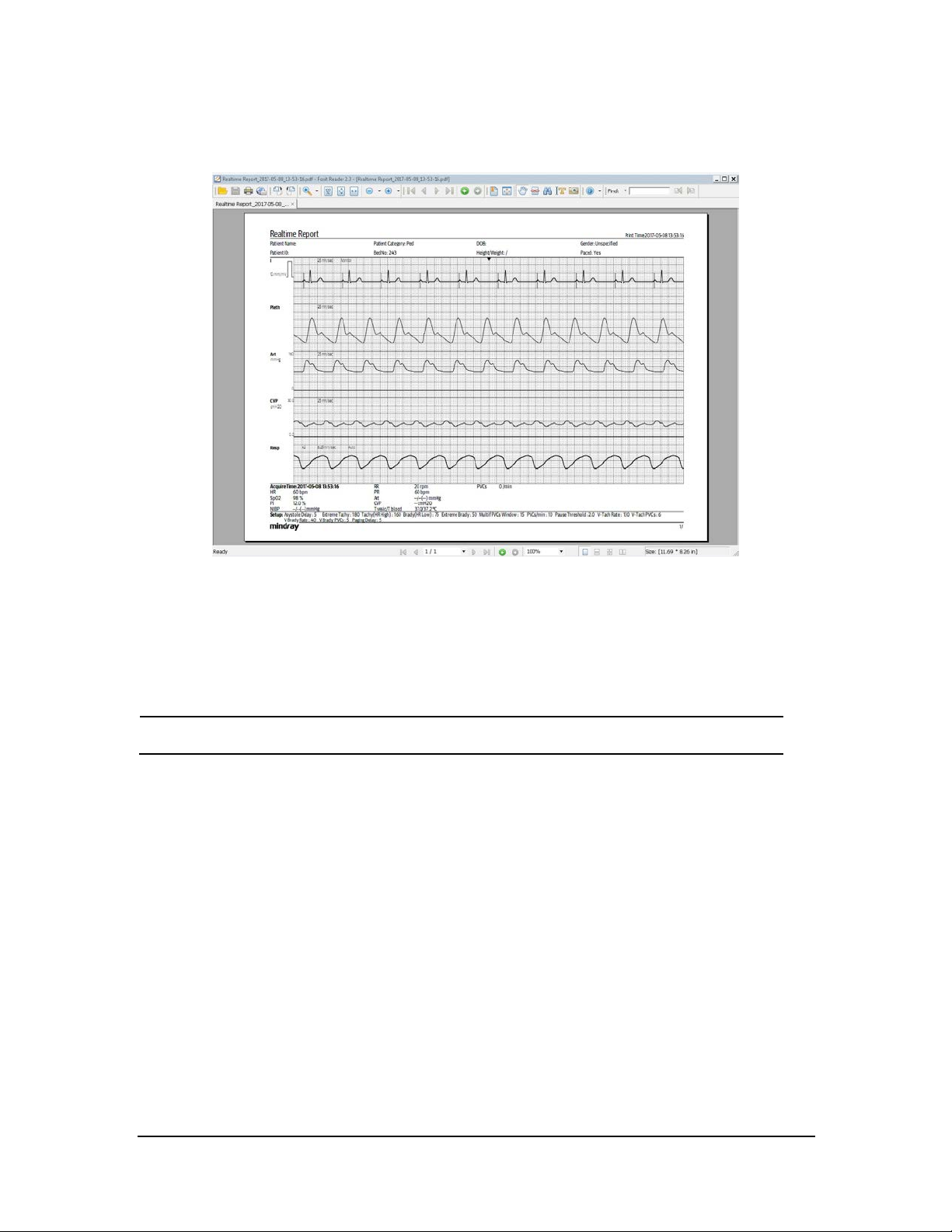
NOTE
The PDF report opened via Foxit is as shown below.
3.8 Installing a Recorder
No recorder driver is needed. Recording can function directly after system sof tware is installed.
Con nect a recorder to CO M1 port of the CMS host.
3.9 CMS System Software Installation
For how to install the CMS system sof tware (running as normal service, see 3.3.17Installing th e CMS System
Softw are (Running As Normal Service).
BeneVision CMS Service Manual 3-75
Page 94

3.9.1 C onfiguring C MS Display S ize
To set th e screen size, follo w this procedu re:
1. Select the system menu area in the upper lef t corner of th e CMS screen.
2. Select
3. Select the Display tab, enter the required password, and then select OK.
4. Select the Screen tab.
5. Select Screen Size an d then select the desired option. If your screen size is n ot available, select Others
and select the + or–button o n the rulers to adjust the screen size.
6. Click OK.
7. Restart th e CMS system to make the changes take effect.
System Setup to a ccess t he System Setup menu.
3.9.2 Setting the Display Layout of CMS Screen
When the CentralStation , the WorkStation, or the ViewStation is equipped with four displays, the “Display
Layout” option is available in the “Screen” tab and allo ws you to chan ge the cursor moving mode. The display
layout selected should be consistent with the appearance of your displays.
To change the display layout, follow this procedure:
1. Right click the mouse on the desktop, and then select Screen Resolution from th e pop-up men u to
display the window.
2. Adjust the layo ut of your displays either 1x4 or 2x2.
1 X4 : Four displays are arranged in a line. You can move the cursor from the current display to its
neighboring diplays.
3-76 BeneVision CMS Service Manual
Page 95
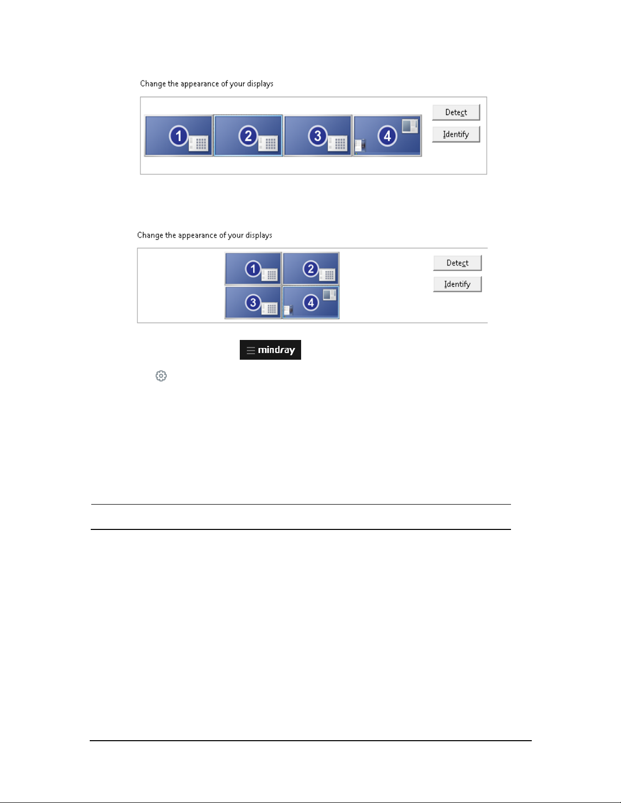
NOTE
2x2 : When two displays are stacked on the other two displays. You can mo ve the cursor from current
display to its neighboring displays.
3. Select the system menu area in the upper lef t corner of th e CMS screen.
4. Select
5. Select the Display tab, enter the required passwo rd, and then select OK.
6. Select the Screen tab.
7. Set Display Layout: either 1x4 or 2x2 . This option should be consistent with the layout of your displays.
8. Restart th e CMS system.
The display setting changes will take effect after the CMS r estarts.
System Setup to a ccess the System Setup menu.
BeneVision CMS Service Manual 3-77
Page 96

NOTE
3.10 Setting AP Management
1. Fro m the CMS system, select the system menu area in the upper left corner of the screen.
2. Select System Setup → Networ k→ enter the passwo rd.
3. Select the AP Management tab.
4. Click Import AP Information to import a file(format:*.txt)
The impor ted text file must be saved in the UTF-8 for mat.
Th e text file that contains the AP information must be in this format: AP Name, Mac address,
Location, Detail. AP Name, Mac address, Location, and Detail are customizable. For
example, AP-CMS1,F84F573B5D10, HY9-7a1,7a1. Each filed is separated by a comma and
there is no spacing between each field.
3-78 BeneVision CMS Service Manual
Page 97

NOTE
3.11 Connecting a CentralStation to WorkStation/ViewStation
This section describes how to conn ect a CentralStation to WorkStation or ViewStation.
Before connecting a Central Station to WorkStation/ViewStation, you need to configure IP addresses in the
CentralStation and WorkStation/ViewStation respectively.
One of the CentralStations needs to be configured as the master ser ver.
3.11.1 C MS Network IP Configuration
1. Select the system menu area in the upper lef t corner of th e CMS screen.
2. Select
3. Select the General tab.
4. Fro m the Centr al Monito ring Networ k Setup section (i.e. central network”, enter 192.168.0.X i nto the
text input box on the rig ht of Master Server IP Address. This is the IP address of the CentralStation that is
going to be the master.
5. Click the
System Setup → Network → enter the password.
button on the right of the text input box for Local IP address and select 192.168.0.X.
BeneVision CMS Service Manual 3-79
Page 98

6. From the Bedside Monitor ing Network Setup section (i.e. patient network), click the button on the
right o f the text input box for Lo cal IP address and select. 172.16.0.X.
7. Click X in the upper right corner to accept the changes.
8. Restart th e system.
NOTE
If the CentralStation that is being set up is the master, enter its own IP address in the
« Master Server IPAddress » field. See the figure above for r eference.
The CentralStation needs to be restarted for changes to take effect.
3.11.2 Configuring WorkStation/ViewStation Network IP Addresses
1. Fro m the WorkStation /ViewStation, select the system menu area in the upper left corner o f
the screen.
2. Select
System Setup → Network Setup → enter th e password.
3. From the Central Monito ring Network Setup section (i.e. central network”, enter 192.168.0.X into the
text input box on the rig ht of Master Server IP Address. This is the IP address of the CentralStation that is
the master.
4. Click the bu tton on the right of the text input box for Local IP addr ess a nd select192.168.0.X.
3-80 BeneVision CMS Service Manual
Page 99

NOTE
5. Click X in the upper right corner to accept the changes.
6. Restart th e system.
The Work Station/ViewStation needs to be restarted for changes to take effect.
3.11.3 Connecting a CentralStation to WorkStation/ViewStation
1. At the WorkStation/ViewStatio n, select the system menu area in the upper left corner of the
screen.
2. Select System Setup → Network Setup → enter the password.
3. Select the Centr al Station Connection tab. The following figure is for reference only.
4. Select the name of the central statio n you wan t to connect.
5. Click Connect and then click X in the upper right corner to close the System Setup window.
BeneVision CMS Service Manual 3-81
Page 100

NOTE
For how to admit patients on the Work Station/ViewStation, r efer to section4 .3 Assigning
Monitoring Devices from the Host CentralStation to the Work Station/ViewStation of the
BeneVision Central Monitoring System Operator ’s Manual (P/N: 046-010879-00) .
For details on troubleshooting the issues that may occur when using the
WorkStation/V iewStation, see chap ter 10 Troubleshooting.
3.12 MLDAP Deployment
For details on the MLDAP deployment, refer to MLDAP Installatio n and User Guide (PN:046-011462-00).
3-82 BeneVision CMS Service Manual
 Loading...