

Mindray H-046-007962-00-BeneVision-CMS-Service-Manual-FDA-6.0 BeneVision Central Monitoring System Service Manual
Page 1

BeneVision
Central Monitoring System
Service Manual
Page 2

Page 3

Intellectual Property Statement
This manual describes all features and options. The equipment may not have all of
them. Contact Mindray service department for any questions.
SHENZHEN MINDRAY BIO-MEDICAL ELECTRONICS CO., LTD. (hereinafter called
Mindray) owns the intellectual property rights to this product and this manual. This manual may
refer to information protected by copyrights or patents and does not convey any license under the
patent rights of Mindray, nor the rights of others. Mindray does not assume any liability arising
out of any infringements of patents or other rights of third parties.
Mindray intends to maintain the contents of this manual as confidential information. Disclosure
of the information in this manual in any manner whatsoever without the written permission of
Mindray is strictly forbidden. Release, amendment, reproduction, distribution, rent, adaptation
and translation of this manual in any manner whatsoever without the written permission of
Mindray is strictly forbidden.
, and are the registered trademarks or trademarks owned by
Mindray in China and other countries. All other trademarks that appear in this manual are used
only for editorial purposes without the intention of improperly using them. They are the property
of their respective owners.
This posting serves as notice under 35 U.S.C.§287(a) for Mindray patents: http://
www.mindrayna.com/patents.
For this manual, the issued Date is 2019-01 (Version: 6.0).
© 2015-2019 Shenzhen Mindray Bio-Medical Electronics Co., Ltd. All rights reserved
NOTE
BeneVision CMS Service Manual I
Page 4

Manufacturer’s Responsibility
Contents of this manual are subject to changes without prior notice.
All information contained in this manual is believed to be correct. Mindray shall not be liable for
errors contained herein nor for incidental or consequential damages in connection with the
furnishing, performance, or use of this manual.
Mindray is responsible for safety, reliability and performance of this product only in the condition
that:
All installation operations, expansions, changes, modifications and repairs of this product
are conducted by Mindray authorized personnel; and
The electrical installation of the relevant room complies with the applicable national and
local requirements; and
This product is operated under strict observance of this manual.
II BeneVision CMS Service Manual
Page 5

Return Policy
In the event that it becomes necessary to return a unit to Mindray, follow the instructions below.
1. Obtain a return authorization.
Contact the Mindray Service Department and obtain a Mindray Customer Service Authorization
Number. The Mindray Customer Service Authorization Number must appear on the outside of the
shipping container. Return shipments will not be accepted if the Mindray Customer Service
Authorization Number is not clearly visible. Please provide the model number, serial number, and
a brief description of the reason for return.
2. Freight policy
The customer is responsible for freight charges when this product is shipped to Mindray for
service (including any relevant customs fees or other freight related charges).
3. Return address
Please send the part(s) or equipment to the address offered by Customer Service Department.
Company Contact
Manufacturer:
Address:
Tel:
Fax:
Website:
Distributor:
Address:
Tel:
Website:
Shenzhen Mindray Bio-Medical Electronics Co., Ltd.
Mindray Building, Keji 12th Road South, High-tech Industrial Park,
Nanshan, Shenzhen 518057 P.R. China
+86 755 81888998
+86 755 26582680
www.mindray.com
Mindray DS USA, Inc.
800 MacArthur Boulevard Mahwah, New Jersey 07430 USA
1.800.288.2121, 1.201.995.8000
www.mindray.com
BeneVision CMS Service Manual III
Page 6

FOR YOUR NOTES
IV BeneVision CMS Service Manual
Page 7

Contents
1 Safety ................................................................................................................................. 1-1
1.1 Safety Information .......................................................................................................... 1-1
1.1.1 Dangers .............................................................................................................. 1-2
1.1.2 Warnings ............................................................................................................. 1-2
1.1.3 Cautions ............................................................................................................. 1-3
1.1.4 Notes .................................................................................................................. 1-3
1.2 Equipment Symbols ........................................................................................................ 1-4
2 Introduction ...................................................................................................................... 2-1
2.1 Overview ......................................................................................................................... 2-1
2.2 Intellectual Property Protection ....................................................................................... 2-1
2.3 Versions ........................................................................................................................... 2-2
3 System Installation ........................................................................................................... 3-1
3.1 Pre-installation Preparations ........................................................................................... 3-1
3.1.1 Environmental Requirements ............................................................................. 3-1
3.1.2 Power Requirements .......................................................................................... 3-1
3.1.3 Power and Heat Requirements ........................................................................... 3-2
3.2 CMS Host ........................................................................................................................ 3-3
3.2.1 Kontron KISS 2U (023-001020-00) ................................................................... 3-3
3.2.2 HP 800G1 (023-000969-00)/HP EliteDesk 800 G2 SFF (023-001325-00) ....... 3-5
3.2.3 Configuring Paging COM Port Settings ............................................................. 3-6
3.3 WorkStation (0998-00-0708-01) ..................................................................................... 3-6
3.4 Display Installation ......................................................................................................... 3-7
3.4.1 Implementing Double Screen Display by DP-to-VGA Adapter ......................... 3-8
3.4.2 Setting My Main Display ................................................................................... 3-9
3.4.3 Aligning the Double Screens ............................................................................ 3-10
3.4.4 Disabling Hot Keys ........................................................................................... 3-11
3.4.5 Installing Multi-Screen Extend Device (SUNIX VGA2715) ........................... 3-12
3.4.6 Setting the Audio Properties (T100 Extend Device Only) ............................... 3-14
3.4.7 Disabling the Audio Enhancement ................................................................... 3-14
3.4.8 Installation for Remote Display, Keyboard/Mouse, Audio .............................. 3-15
3.4.9 Installing Elo Touchscreen Driver (Optional) .................................................. 3-21
3.4.10 Installing Synergy Software (Optional) ......................................................... 3-24
3.5 Installing/Updating OS Patches .................................................................................... 3-29
3.6 IP Address Setup and Network Connection .................................................................. 3-30
3.6.1 Network Connection Using Multiple Network Adapters ................................. 3-31
3.6.2 Monitor Network .............................................................................................. 3-32
BeneVision CMS Service Manual 1
Page 8

3.6.3 External Network ............................................................................................. 3-36
3.7 Installing the Micro Dog Driver .................................................................................... 3-37
3.8 Installing Database Software ......................................................................................... 3-38
3.9 Installing Printers .......................................................................................................... 3-39
3.9.1 Supported Printers ............................................................................................ 3-39
3.9.2 Printer Installation Procedures ......................................................................... 3-40
3.9.3 Tasks after Printer Installation .......................................................................... 3-45
3.10 Installing a Recorder ................................................................................................... 3-47
3.11 Installing CMS Software ............................................................................................. 3-47
3.11.1 Setting the Region and Language of the Operating System ........................... 3-47
3.11.2 Setting Operating System Time ...................................................................... 3-48
3.11.3 Installing the CMS System Software ............................................................. 3-48
3.11.4 Setting the Size of CMS Screen ..................................................................... 3-51
3.11.5 Initial Database Backup .................................................................................. 3-52
3.12 USB Dongle Compatibility ......................................................................................... 3-55
3.13 Connecting a CentralStation to WorkStation/ViewStation .......................................... 3-55
3.13.1 Configuring Network IP Addresses in CentralStation .................................... 3-55
3.13.2 Configuring Network IP Addresses in WorkStation/ViewStation .................. 3-57
3.13.3 Connecting a CentralStation to WorkStation/ViewStation ............................. 3-58
4 About Telemetry Monitoring System (TMS) ................................................................. 4-1
4.1 Setting the Panorama Telemetry Server .......................................................................... 4-1
4.2 Programming a Panorama Telepack 608 to BeneVision CMS ........................................ 4-5
4.3 Admitting a Panorama Telepack 608 to BeneVision CMS .............................................. 4-6
4.4 Programming Replacement Panorama Telepack 608 ...................................................... 4-6
5 McAfee Solidcore S3 Control .......................................................................................... 5-1
5.1 Installation ....................................................................................................................... 5-1
5.2 Enabling the Solidifier .................................................................................................... 5-2
5.3 Adding or Editing Additional Applications ..................................................................... 5-3
5.3.1 Performing Updates via sadmin bu and sadmin eu ............................................ 5-4
5.3.2 Performing Updates via sadmin disable and sadmin enable .............................. 5-4
6 System Recovery .............................................................................................................. 6-1
6.1 Overview ......................................................................................................................... 6-1
6.2 HDD Replacement Procedure ......................................................................................... 6-1
6.2.1 Tools Required ................................................................................................... 6-1
6.2.2 Rebuilding a Defective Hard Drive .................................................................... 6-2
6.2.3 Replacing Both Hard Drives in a RAID Configured BeneVision CMS ............. 6-3
6.3 Database Recovery ........................................................................................................ 6-29
6.3.1 Recovering the Database for CentralStation .................................................... 6-29
2 BeneVision CMS Service Manual
Page 9

6.3.2 Recovering the Database for WorkStation/ViewStation ................................... 6-32
6.4 Database Backup ........................................................................................................... 6-32
6.5 Configuring Printer ....................................................................................................... 6-32
6.6 Installing Dual Displays ................................................................................................ 6-32
6.7 Installing Multiple Displays .......................................................................................... 6-32
6.8 Setting the Size of CMS Screen .................................................................................... 6-33
6.9 Setting Language and Time ........................................................................................... 6-33
7 Maintenance and Cleaning .............................................................................................. 7-1
7.1 Maintenance .................................................................................................................... 7-1
7.1.1 General Inspection ............................................................................................. 7-1
7.1.2 System Performance Test ................................................................................... 7-2
7.2 Cleaning .......................................................................................................................... 7-2
7.3 Preventative Maintenance ............................................................................................... 7-3
7.3.1 Display Monitors ................................................................................................ 7-3
7.3.2 LCD Display Chassis ......................................................................................... 7-4
7.3.3 Care and Cleaning of the Screen/Touchscreen ................................................... 7-4
7.3.4 CMS Chassis, Gateways, Telemetry Server Chassis and Wireless Transceiver . 7-5
7.3.5 Uninterruptible Power Supplies (UPS) .............................................................. 7-5
7.3.6 CMS Network Equipment Racks ....................................................................... 7-6
7.3.7 System Maintenance Schedule ........................................................................... 7-6
7.4 BIOS Settings .................................................................................................................. 7-7
7.4.1 BIOS Settings for Kontron KISS 2U (023-001020-00) Central Station, ViewStation,
WorkStation ................................................................................................................. 7-7
7.4.2 BIOS Settings for RM/VM Central Station, ViewStation, WorkStation and Gate
(0998-00-0708-01, 0998-00-0709-01) ...................................................................... 7-10
8 Parts .................................................................................................................................. 8-1
9 Troubleshooting ................................................................................................................ 9-1
9.1 The displaying text on the CMS screen is abnormal. ...................................................... 9-1
9.2 Recorder/printer-related technical alarm messages ......................................................... 9-1
9.3 Network printing fails ..................................................................................................... 9-2
9.4 No waveform displayed in waveform review ................................................................. 9-2
9.5 Multi-/Dual-screen changes to Single-screen during the CMS installation .................... 9-2
9.6 Remove Dongle Error ..................................................................................................... 9-3
9.7 CMS Unable to Connect the Bedside Monitor ................................................................ 9-3
9.8 Abnormal Database Service Handling ............................................................................ 9-3
9.9 Database Backup and Recovery in Case of System Failure ............................................ 9-4
9.10 eGateway Unable to Obtain the Exported Files from the CMS .................................... 9-4
BeneVision CMS Service Manual 3
Page 10

FOR YOUR NOTES
4 BeneVision CMS Service Manual
Page 11

DANGER
Indicates an imminent hazard situation that, if not avoided, will result in death
or serious injury.
WARNING
Indicates a potential hazard situation or unsafe practice that, if not avoided,
could result in death or serious injury.
CAUTION
Indicates a potential hazard or unsafe practice that, if not avoided, could result
in minor personal injury or product/property damage.
NOTE
Provides application tips or other useful information to ensure that you get the
most from your product.
1 Safety
1.1 Safety Information
BeneVision CMS Service Manual 1-1
Page 12

WARNING
The device is intended for use only by clinical professionals or under their
guidance. It must only be used by persons who have received adequate training
in its use. Anyone unauthorized or untrained must not perform any operation
on it.
The CMS is a clinical information device. Except for using such components as
the mouse and keyboard to perform normal operations, do not touch or
disassemble any other component, especially the power component; otherwise, it
may result in personnel injury.
Do not connect this system to outlets with the same circuit breakers and fuses
that control current to devices such as life-support systems. If this system
malfunctions and generates an overcurrent, or when there is an instantaneous
current at power ON, the circuit breakers and fuses of the building’s supply
circuit may be tripped.
Failure on the part of the responsible hospital or institution employing the use of
the CMS to implement a satisfactory maintenance schedule may cause undue
equipment failure and possible health hazard.
Be sure to keep the packaging materials from children’s reach. Disposal of the
packaging materials shall comply with your local requirements.
If any value displayed on the screen of the CMS is abnormal or questionable,
first determine the patient’s vital signs by alternative means and then verify that
the CMS or monitor is working correctly.
The physiolgical waveforms, parameters and alarms displayed on the CMS are
tarnsmitted from the monitor through the network. If there is a network failure,
the data loss or delay may occur. Pay close attention to the patients during a
network failure.
1.1.1 Dangers
There are no dangers that refer to the product in general. Specific “Danger” statements may be
given in the respective sections of this operation manual
1.1.2 Warnings
1-2 BeneVision CMS Service Manual
Page 13

CAUTION
Hospitals without stable power source should use an Uninterruptible Power
Supply (UPS) to power the CMS. When there is a power failure, the system
should be shut down by following the specified shutdown procedure before the
UPS is turned off. If the system has a sudden power failure, system failure may
occur and consequently the system will not work correctly next time or even
have a serious result.
The host of the CMS should be installed with the original Microsoft Windows’s
system and standard upgrade program, such as the service package. Illegal
software may lead to abnormal or incorrect system operating.
The host of the CMS should be maintained every three to six months. Its long
time continuous operating may lead to failure of the operating system.
Protect the device from damage caused by drop, impact, strong vibration or
other mechanical force during servicing.
NOTE
Refer to the Operator’s manual for more information.
1.1.3 Cautions
1.1.4 Notes
BeneVision CMS Service Manual 1-3
Page 14
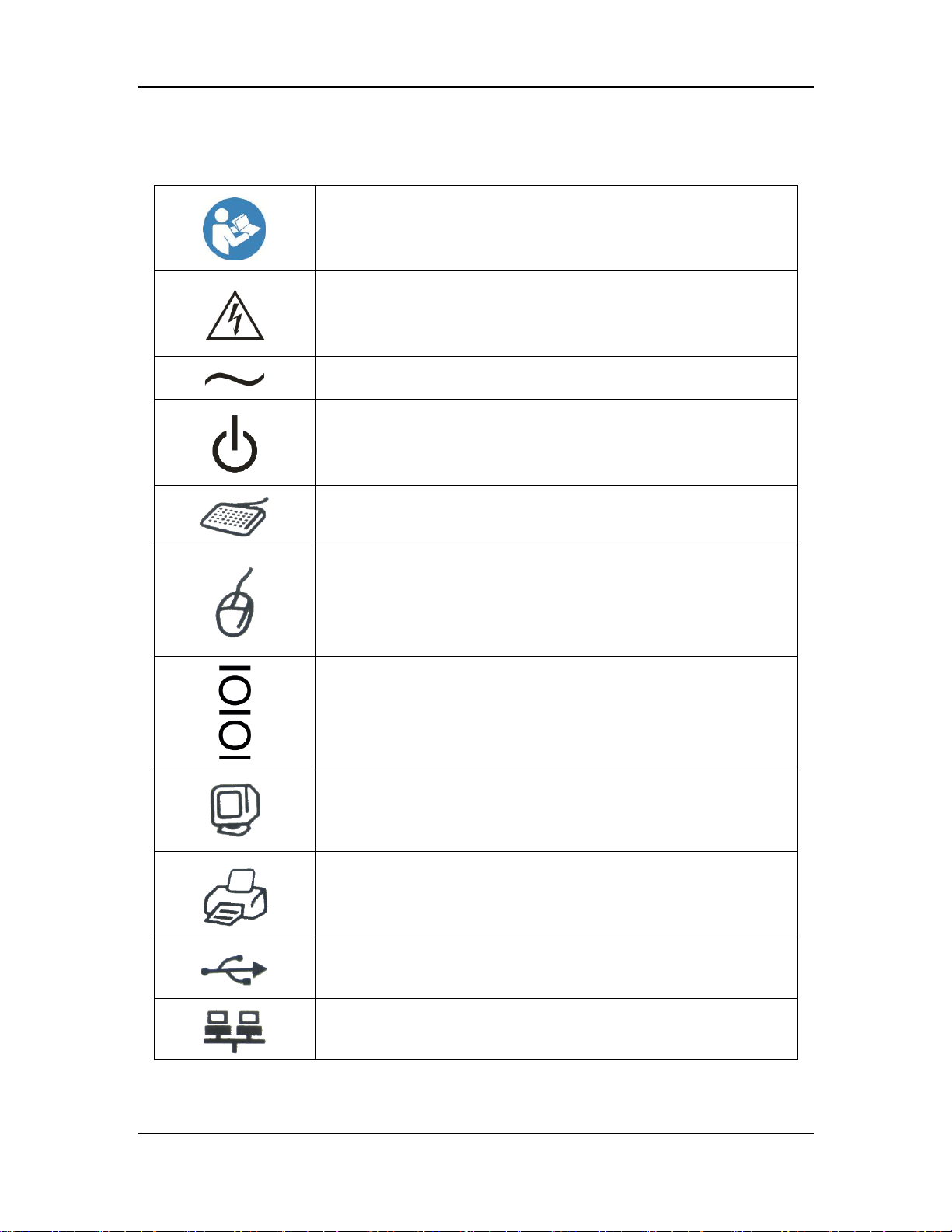
Refer to instruction manual/booklet.
CAUTION: To reduce the risk of electric shock, do NOT remove
cover. Refer servicing to qualified service personnel.
Alternating current
Power switch
Keyboard port
Mouse port
Serial communication(COM)port
Display port
Printer port
USB port or device
Network port
1.2 Equipment Symbols
1-4 BeneVision CMS Service Manual
Page 15
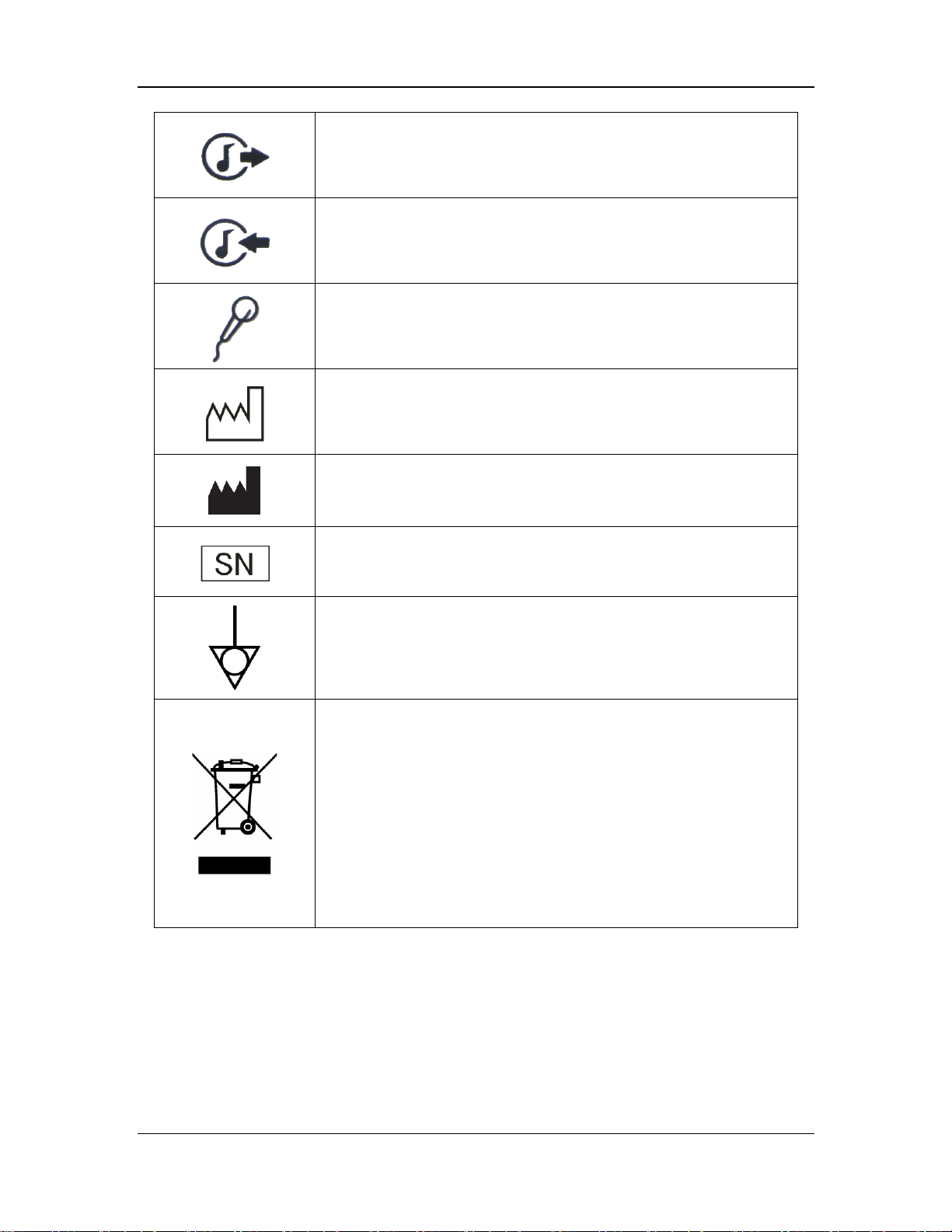
Sound output port
Sound input port
Microphone port
DATE OF MANUAFACTURE
MANUFACTURER
Serial number
Equipotentiality
The following definition of the WEEE label applies to EU member
states only.
This symbol indicates that this product should not be treated as
household waste. By ensuring that this product is disposed of correctly,
you will help prevent bringing potential negative consequences to the
environment and human health. For more detailed information with
regard to returning and recycling this product, please consult the
distributor from whom you purchased it.
* For system products, this label may be attached to the main unit only.
BeneVision CMS Service Manual 1-5
Page 16

FOR YOUR NOTES
1-6 BeneVision CMS Service Manual
Page 17

NOTE
When installing or using the CMS, you must plug in the USB dongle.
NOTE
When reinstalling the system software, try not to remove the old database so as
to keep the old monitoring data.
2 Introduction
2.1 Overview
BeneVision Central Monitoring System (hereinafter called CMS), including CentralStation,
WorkStation and ViewStation, is intended for professional physicians or paramedics to conduct
centralized monitoring over patients monitored by Mindray individual monitors and/or telemetry
systems in hospitals or medical institutions.
The central monitoring system comprises powerful system software and high-performance
computer. It constructs a monitoring network by connecting monitors and/or telemetry. By
collecting, processing, analysing and outputting the information coming from monitors and/or
telemetry, the central monitoring system can achieve centralized monitoring over multiple
patients so as to greatly promote the efficiency and quality of the monitoring work.
2.2 Intellectual Property Protection
The BeneVision Central Monitoring System uses a USB dongle for intellectual property
protection. You must plug the dongle into the system’s USB interface before starting the system.
Otherwise, the system cannot start.
If the dongle is damaged or lost, you may need to reinstall the system software before using a
new one.
BeneVision CMS Service Manual 2-1
Page 18
CMS System Software
Dongle
Service Manual
02.01.XX
04.00.XX
1.0
02.01.XX
04.00.XX
2.0
02.02.01.01
04.00.XX
3.0
02.04.00.01
04.00.XX
5.0
2.3 Versions
The CMS system software, dongle and service manual versions correspond to each other as
below.
2-2 BeneVision CMS Service Manual
Page 19

WARNING
Make sure that the operating environment and power source of the CMS meet
the specific requirements; otherwise, unexpected consequences, e.g. damage to
the equipment, may result.
3 System Installation
3.1 Pre-installation Preparations
3.1.1 Environmental Requirements
The CMS should be installed in an environment where the system can be easily viewed, operated
and maintained.
The environment where the CMS is installed should be reasonably free from noises, vibration,
dust, and corrosive, flammable and explosive substances.
If the CMS is installed in a cabinet, sufficient space in front and behind should be left for
convenient operation, maintenance and repair. Moreover, to maintain good ventilation, the CMS
should be at least 2 inches (5cm) away from around the cabinet.
When the CMS is moved from one place to another, condensation may occur as a result of
temperature or humidity difference. In this case, never start the system before the condensation
disappears.
3.1.2 Power Requirements
Each component of the CMS must be powered by the specified power source.
To protect the hospital personnel from electric shock, the CMS (including the host and displays)
and its recorder must have their casings properly grounded. The host of the CMS is provided with
a 3-wire power cable, which must be plugged into a properly grounded 3-wire receptacle. If a
3-wire, grounded receptacle is not available, consult the hospital electrician.
BeneVision CMS Service Manual 3-1
Page 20

WARNING
Appropriate power supply must be selected according to the setup of the system
power voltage; otherwise, serious damage may be caused to the system.
Never use a 3-wire to 2-wire adapter with any unit of the CMS.
The CMS host cannot be installed with any other software besides the Windows
system, necessary drivers, and drivers/software listed in this manual. Otherwise,
normal operation of CMS may be affected and unexpected consequences may
result.
NOTE
The CMS software only supports Windows® 7 Professional Embedded SP1
(32bit) operating system.
Before performing the operations described below, make sure that the main unit
is not installed with any application software except the accompanying software
of Windows.
QTY
Host
Item
Watt/per
Watt/Total
Max BTU
1
Kontron KISS 2U
CS
400
400
1364
1
HP EliteDesk 800
G2 SFF
CS
200
200
682
4
ELO 1929LM
LED
28
112
381.92
1
HP 1920-48G-POE
Switch
492
492
1677.72
1
HP 1920-48G
Switch
32
32
109.12
1
Cisco
Air-ct2504-5-k9
AP
12.95
12.95
44.1595
4
ATEN CE750
KVM
7.2
28.8
98.208
1
Tripp Lite - SMART
1500 RM2U
UPS
1350
1350
4603.5
3.1.3 Power and Heat Requirements
The following table lists the power and heat requirements.
3-2 BeneVision CMS Service Manual
Page 21

QTY
Host
Item
Watt/per
Watt/Total
Max BTU
1
Tripp Lite - SMART
3000 RM 2U
UPS
2250
2250
7672.5
1
Tripp Lite SU3000RTXL3U
UPS
2400
2400
8184
Total
7277.75
24817.13
LAN2
(Hospital NetWork)
LAN
(Patient NetWork)
DP2 Monitor2
DP1 Montor1
DP3 Monitor3
Audio
COM2
(Paging)
COM 1
(Recorder/Programming)
DVI Monitor4
USB 2.0(Keyboard/Mouse/USB module devices
USB 3.0(Keyboard/Mouse/USB module devices
Redundant Power
3.2 CMS Host
3.2.1 Kontron KISS 2U (023-001020-00)
Connectors
BeneVision CMS Service Manual 3-3
Page 22

Assembly Diagram
DVD recorder (P/N:
023-001209-00)
Motherboard
(P/N: 023-001212-00)
CPU i5-4570S 22nm
FCLGA1150
(P/N: 023-001202-00)
Power Supply Unit
(PSU) (P/N:
023-001201-00)
Harddisk 500GB
SATA6Gb/s
(P/N: 023-001203-00)
USB3.0 to DVI-I
Graphics Dongle
(P/N: 023-001204-00)
Memory,
VL37B5263A-K9SD
(4G)(P/N:023-001205
3-4 BeneVision CMS Service Manual
Page 23

KeyboardAudio
Mouse
VGA Montior1
RS-232(COM1
Recorder/Programming
Telepacks)
DP Monitor2
DP Montor3
LAN1
(Hospital NetWork)
LAN2
(Patient NetWork)
Power
USB 3.0
USB 2.0
USB 2.0
1. Uncover
the label.
2. Pull up
the cover.
3. Pull up the
HDD holder.
3.2.2 HP 800G1 (023-000969-00)/HP EliteDesk 800 G2 SFF (023-001325-00)
Connectors
Please be noted that a USB to RS-232 adapter (PN 023-000739-00) and a RS-232 cable (PN
300A-10-f08997) are required to connect a paging to 800G1/G2 computer.
Inserting a USB Dongle
BeneVision CMS Service Manual 3-5
Page 24

4. Insert the USB dongle
to the white port, and fix
it with a cable tie.
3.2.3 Configuring Paging COM Port Settings
To configure Paging COM port settings, follow this procedure:
1. Open the ConfigDir folder in the directory where the CMS software is installed: C:\Program
Files\Mindray CMS\ConfigDir.
2. Open the configuration file named as Paging.ini.
3. Configure the following settings:
Comport=2; // COM Port
baudrate=9600; // Bits per second
databit=8; //Data bits
stopbit=1; //Spot bits
parity=N; //Parity
3.3 WorkStation (0998-00-0708-01)
3-6 BeneVision CMS Service Manual
Page 25

CD-RW Drive SATA
(P/N:
0992-00-0178-02)
Disclosure Hard
Drive 250 GB min.
(SATA) (P/N:
0992-00-0287)
System Hard Drive
160 GB min. (SATA)
(Use P/N:
0992-00-0287)
Power Supply ATX
300 W min.
(P/N: 0014-00-0094)
Mother Board Intel
Dual Core (P/N:
0671-00-0115)
Clock card (PCI)
(P/N: 0671-00-0267)
Riser Card
(P/N:0671-00-0268)
Video Expansion Card
(P/N: 0671-00-0116)
Assembly Diagram
3.4 Display Installation
From this section on, the following sections in this chapter describe how to set up all the devices
(such as displays, printer, and recorder) that are going to be used with this system and how to
connect them to the Central Station.
BeneVision CMS Service Manual 3-7
Page 26
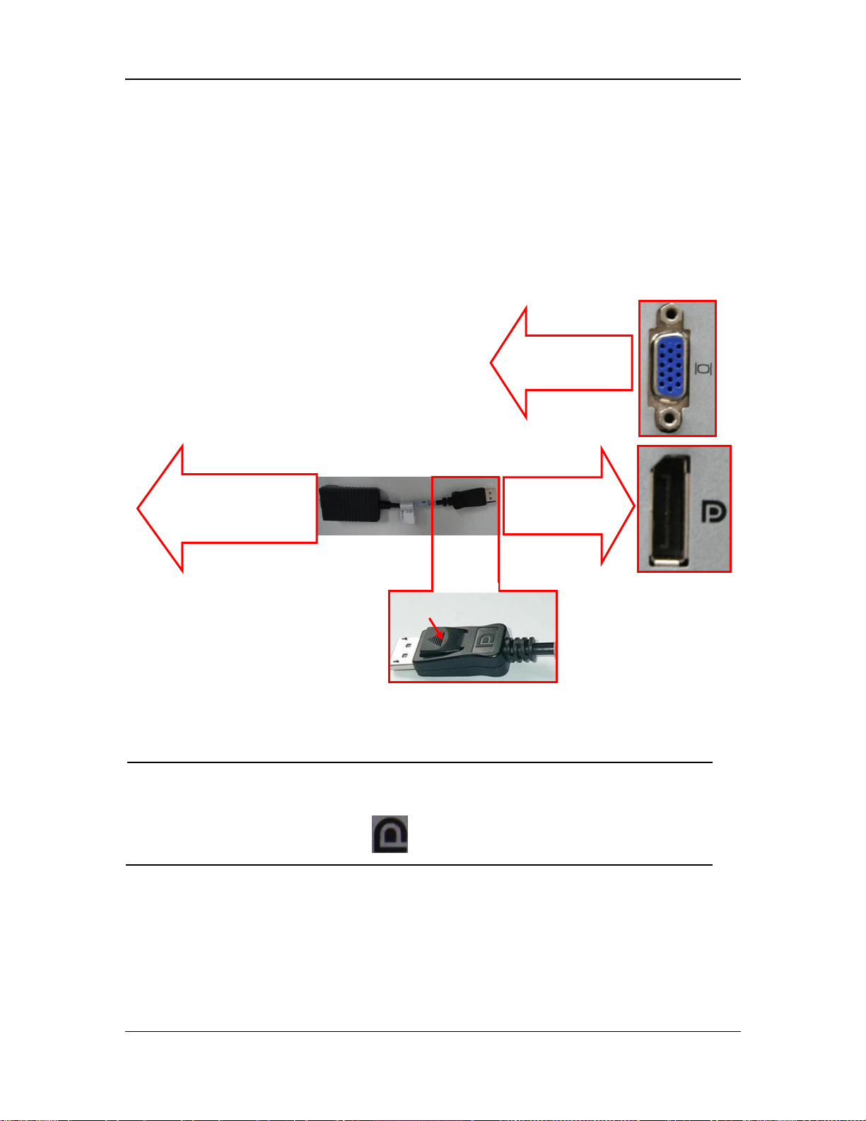
NOTE
When unplugging the DP-to-VGA adapter, press the spring button on the DP
plug and then unplug it downward. Failure to do so may damage the DP plug.
The label beside DP port is .
Connect display’s
VGA cable
Connect DP
port
Connect
display’s VGA
The plug has a spring
3.4.1 Implementing Double Screen Display by DP-to-VGA Adapter
The double screen display in the CMS can be achieved by DP-to-VGA adapter:
1. Shut down the computer first.
2. Then connect two screens by DP-to-VGA adapter:
3-8 BeneVision CMS Service Manual
Page 27

3
3.4.2 Setting My Main Display
To make the desired screen as main display, follow this procedure:
1. Right click the mouse on the desktop, and then select “Screen resolution” from the pop-up
menu to display the window, as shown in the following figure.
2. In the screens displaying list box, select the desired screen.
3. Select the “Make this my main display” option.
4. Click the “OK” button to save the setting and close the window.
BeneVision CMS Service Manual 3-9
Page 28

3.4.3 Aligning the Double Screens
When the alignment between the screens is ragged, follow this procedure to align the screens at
the same horizontal line:
1. Right click the mouse on the desktop, and then select “Screen resolution” from the pop-up
menu to display the window, as shown in the following figure.
2. Click the screen signed with number 1 to select it, and then drag the screen down until the
screen signed with number 1 aligns with the screen signed with number 2.
3. Click the “OK” button to save the setting and close the window.
You can refer the above steps to adjust the multi-screens alignment.
3-10 BeneVision CMS Service Manual
Page 29
3.4.4 Disabling Hot Keys
To avoid the misoperation, you can disable hot keys. There are two ways to disable the hot keys.
3.4.4.1 Disabling All the Hot Keys At One Go
Follow this procedure to disable all the hot keys at one go.
1. Right click on the Desktop.
2. Select Graphics Options.
3. Select Hot Keys.
4. Select Disable.
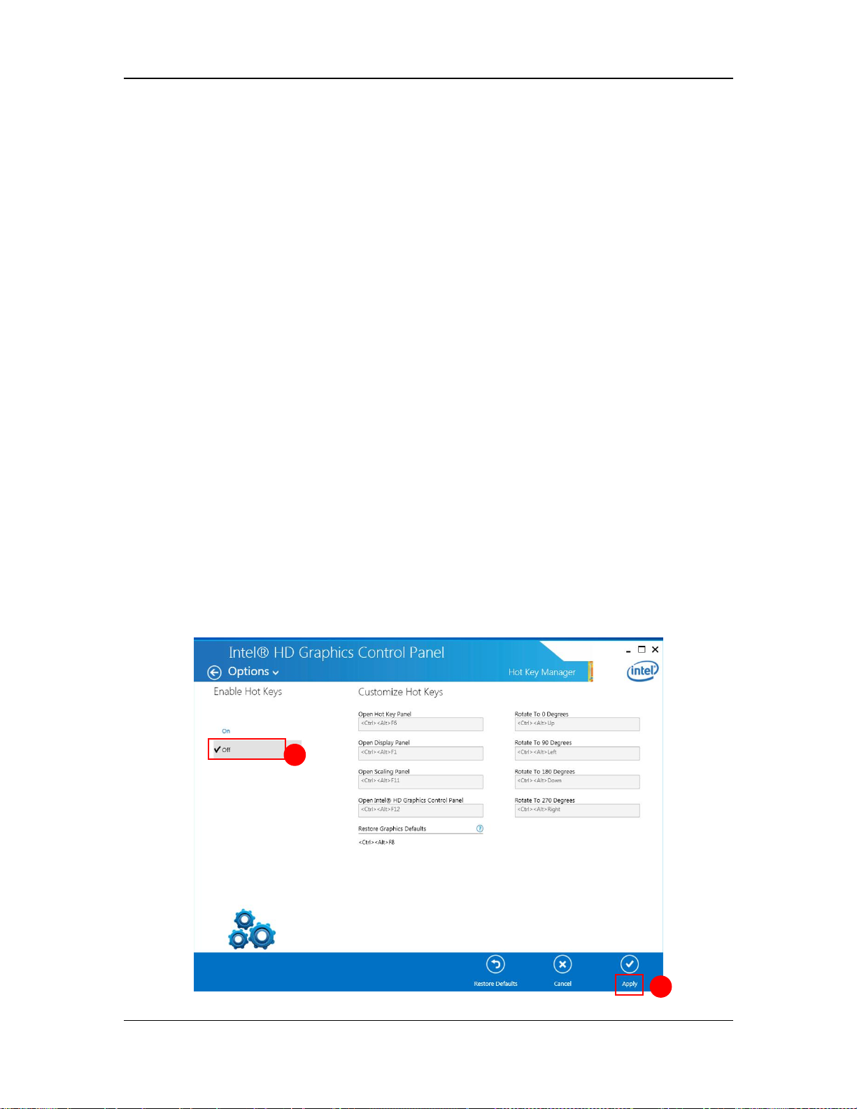
3.4.4.2 Disabling the Desired Hot Keys
Follow this procedure to disable the desired hot keys:
1. Right click on the Desktop.
2. Select Graphics Properties.
3. Enter the “Intel ® HD Graphics Control Panel” window, and then click the “Options” button
to display the “Hot Key Manager” window, as shown in the following figure.
BeneVision CMS Service Manual 3-11
Page 30
NOTE
The SUNIX VGA is used for systems that do not have the DP port. If a system
has a DP port, DP port should be used as primary.
Three Display Menu
Four Display Menu
VGA2715 icon
3. In the “Enable Hot Keys” field, click the “Off” option.
4. Click the “Apply” option to apply the setting. The message “The new settings have been
applied. Do you want to keep these settings?” displays.
5. Click the “Yes” button to apply the setting.
6. Click the icon to close the window.
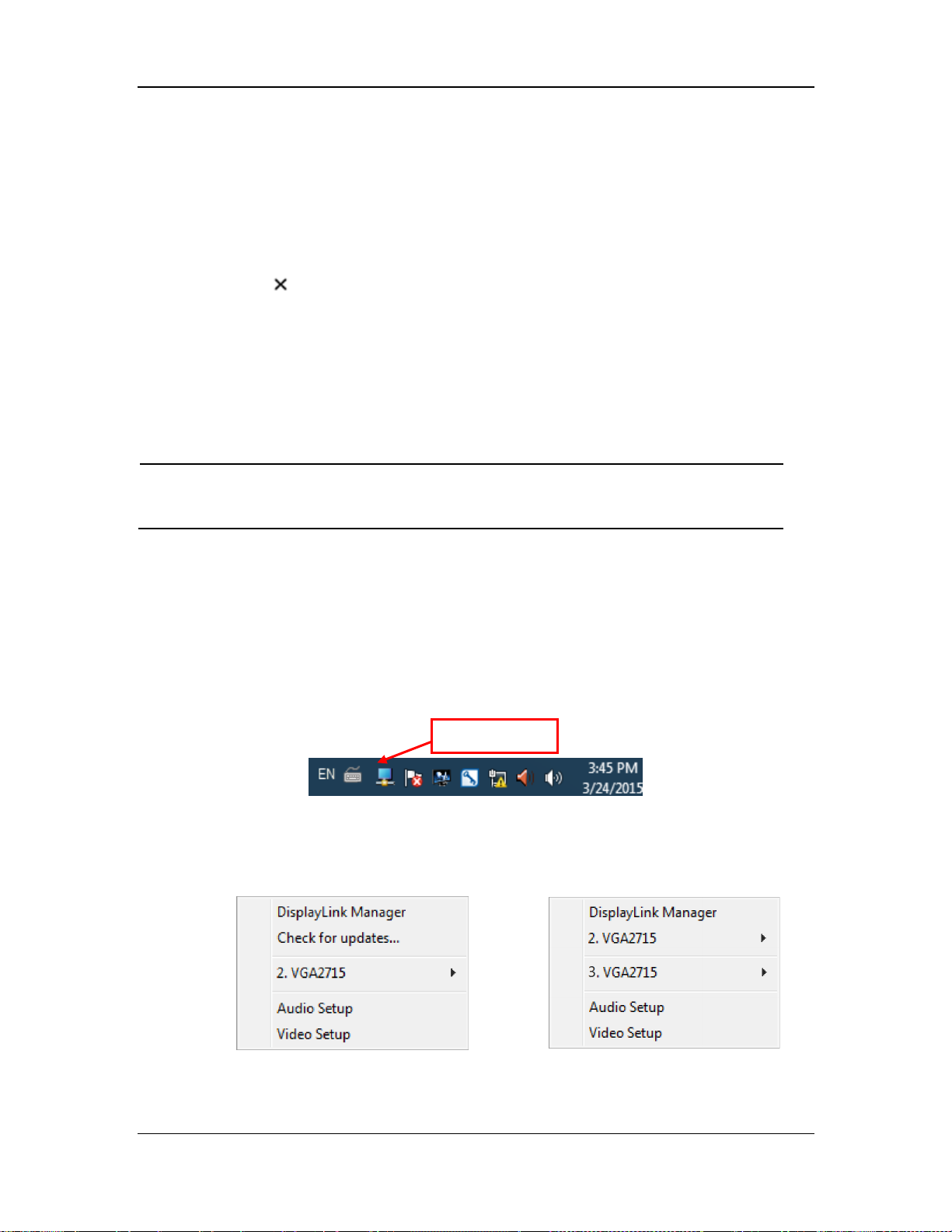
3.4.5 Installing Multi-Screen Extend Device (SUNIX VGA2715)
1. Take out the accompanying USB cable. Connect one end of the cable with the connector of
SUNIX VGA2715, and the other end with the CMS.
2. Place the SUNIX VGA2715 driver CD in the CMS drive. Double click the driver in the CD
and install by default configuration. The following icon will display in menu bar on the
lower right corner of screen when installation is complete.
3. Connect the VGA cable of display with SUNIX VGA2715. Right click VGA2715 icon in the
menu bar. When the CMS are equipped with three or four displays, the following menu will
pop up.
3-12 BeneVision CMS Service Manual
Page 31

Drag individual
display icon to adjust
display sequence.
4. Select the arrow to open the submenu.
5. Select the option of “Extend” in the corresponding submenu. Then the extension of the
screen is done.
6. To adjust the display sequence, select the option of Advanced from the pop-up menu or
sub-menu. The following Display Properties window will show. Set the sequence in the
“Settings” tab. Click “Apply” to save your settings.
BeneVision CMS Service Manual 3-13
Page 32

3.4.6 Setting the Audio Properties (T100 Extend Device Only)
1. Open “Control Panel”, and then select “Hardware and Sound”.
2. Select “Sound”. The “Sound” window will display.
3. In the “Playback” tab, select the operating system speaker and then select “Set Default”
button, shown as below.
4. Restart PC when the above installation is done. Verify that the display effect meets the
requirement.
3.4.7 Disabling the Audio Enhancement
1. Open “Control Panel”, and then select “Hardware and Sound”.
2. Select “Sound”. The “Sound” window will display.
3. In the “Playback” tab, select the operating system speaker and then right click the mouse.
4. In the pop-up menu, select “Properties”.
5. In the pop-up “Speaker Properties” window, select the “Enhancements” tab.
6. Select “Disable all enhancements”, shown as below.
3-14 BeneVision CMS Service Manual
Page 33

NOTE
Install the touchscreen driver only after all the connections are complete.
7. Select “Ok”.
3.4.8 Installation for Remote Display, Keyboard/Mouse, Audio
The CMS supports the remote display, audio, and keyboard/mouse operation with the source
from local CMS.
3.4.8.1 Connection Diagrams
This section describes the connection diagrams for Kontron KISS 2U,HP 800G1/G2, and
WorkStation.
In the connection diagrams for Kontron KISS 2U and HP 800G1/G2, four touch displays are used
for illustration only. If you need to connect one, two, or three touch displays, you do not need to
configure all of the ports for the four touch displays. Please connect the desired number of touch
displays by referring to the connection diagrams below.
BeneVision CMS Service Manual 3-15
Page 34

USB
USB
Keyboard/Mouse
DP
DP to VGA Adapter
(023-000214-00)
Local 1
Audio
CE750 L
USB
DP
DP to VGA Adapter
(023-000214-00)
Local 2
CE750 L
USB
USB to RS-232 Adapter+RS-232 Cable
(023-000739-00+300A-10-08997)
DP
DP to VGA Adapter
(023-000214-00)
Local 3
CE750 L
USB
USB to RS-232 Adapter+RS-232 Cable
(023-000739-00+300A-10-08997)
DVI
DVI to VGA Adapter
(Accompanied in Kontron)
Local 4
CE750 L
Audio
VGA Cable
RS-232 Cable
(Accompanied in Elo)
Cat 5e Cable
Remote 1
Touch Display
CE750 R
Remote 2
VGA Cable
RS-232 Cable
(Accompanied in Elo)
Cat 5e Cable
Touch Display
CE750 R
Remote 3
VGA Cable
RS-232 Cable
(Accompanied in Elo)
Cat 5e Cable
Touch Display
CE750 R
Remote 4
VGA Cable
RS-232 Cable
(Accompanied in Elo)
Cat 5e Cable
Touch Display
CE750 R
Kontron 2U
USB to RS-232 Adapter+RS-232 Cable
(023-000739-00+300A-10-08997)
USB to RS-232 Adapter+RS-232 Cable
(023-000739-00+300A-10-08997)
Keyboard/Mouse
Connection Diagram for Kontron KISS 2U
As shown in this figure, a USB to RS-232 adapter (023-000739-00) is required. Before using this
adapter, you need to insert the adapter CD into the CD ROM and run the “Setup.exe” program to
install the adapter driver.
3-16 BeneVision CMS Service Manual
Page 35

VGA
USB
VGA cable
Local 1
LONGVIEW L
DP
USB
DP to VGA Adapter
(023-000214-00)
Local 2
DP
USB
USB-to-VGA adapter
023-000766-00
Local 3
USB
USB
Local 4
Audio
VGA Cable
RS-232 Cable
(Accompanied in Elo)
Cat 5e Cable
Remote 1
Touch Display
LONGVIEW R
Remote 2
VGA Cable
RS-232 Cable
(Accompanied in Elo)
Cat 5e Cable
Touch Display
Remote 3
VGA Cable
RS-232 Cable
(Accompanied in Elo)
Cat 5e Cable
Touch Display
Remote 4
VGA Cable
RS-232 Cable
(Accompanied in Elo)
Cat 5e Cable
Touch Display
HP800G1/G2
USB to RS-232 Adapter
(023-000739-00)
Keyboard
DP to VGA Adapter
(023-000214-00)
LONGVIEW L
LONGVIEW L
LONGVIEW L
Mouse
LONGVIEW R
LONGVIEW R
LONGVIEW R
Audio
USB to RS-232 Adapter
(023-000739-00)
USB to RS-232 Adapter
(023-000739-00)
USB to RS-232 Adapter
(023-000739-00)
Connection Diagram for HP 800G1/G2-LongView
As shown in this figure, a USB toVGA adapter (023-000766-00) is required. Before using this
adapter, you need to install the adapter driver.
Follow this procedure to install the adapter driver.
1. Run the adapter driver executable file.
BeneVision CMS Service Manual 3-17
Page 36

During the installation process, the following screen displays.
2. Upon completion of installation, select “Desktop” ”Screen Resolution” to check if the
installation is successful. The following figure indicates successful installation.
3-18 BeneVision CMS Service Manual
Page 37

VGA Monitor 1
COM3
VGA cable
Local 1
LONGVIEW L
VGA Monitor 2
COM4
Local 2
Audio
VGA Cable
RS-232 Cable
(Accompanied in Elo)
Cat 5e Cable
Remote 1
Touch Display
LONGVIEW R
Remote 2
VGA Cable
RS-232 Cable
(Accompanied in Elo)
Cat 5e Cable
Touch Display
0998-00-0708-01 WorkStation
Keyboard
LONGVIEW L
Mouse
LONGVIEW R
Audio
RS-232 Cable
(300A-10-08997)
RS-232 Cable
(300A-10-08997)
VGA cable
Connection Diagram for WorkStation (0998-00-0708-01)
3.4.8.2 Installation Procedures
The following installation procedures are illustrated on the Kontron KISS 2U.
Tools Required:
KVM extender (CE750R, CE750L) 023-000773-00
DP-to-VGA adapter 023-000214-00
USB-to-VGA adapter 023-000766-00
RS-232 cable 300A-10-08997
USB-to-RS232 adapter 023-000739-00
1. Connect the Local 1 devices to CE750L.
a. Connect one end of the DP-to-VGA adapter to the DP1 port of Kontron KISS 2U host.
b. Connect the yellow end of the CE750L accompanying cable to the CE750 input port.
c. Connect the VGA port of the CE750L accompanying cable to the DP-to-VGA adapter.
d. Connect the USB port of the RS-232 adapter to the USB 3.0 port of the Kontron KISS
2U host, and the other end to CE750L.
e. Connect the USB port of the CE750L accompanying cable to the USB 2.0 connector of
Kontron KISS 2U host.
f. Connect the audio port of the CE750L accompanying cable to the audio port of the
Kontron KISS 2U host.
2. Connect the Remote 1 devices to CE750R.
BeneVision CMS Service Manual 3-19
Page 38

CAUTION
If recorder is extended for remote operation, the serial port of CE750L must be
connected to the COM1 port of Kontron KISS 2U.
If paging is extended for remote operation, the serial port of CE750L must be
connected to the COM2 port of Kontron KISS 2U.
a. Connect the RS-232 port of touchscreen to the RS-232 port of CE750R by the
touchscreen accompanying cable.
b. Connect the VGA port of touchscreen with the VGA port of CE750R by the
touchscreen accompanying cable.
c. Connect the audio port of touchscreen with the audio port of CE750R by the
touchscreen accompanying cable.
d. Connect the keyboard and mouse to the USB port of CE750R.
3. Connect the Local 2 devices to CE750L.
Repeat the operation a-d of Step 1.
4. Connect the Remote 2 devices to CE750R
Repeat the operation a-c of Step 2.
5. Connect the Local 3 devices to CE750L.
Repeat the operation a-d of Step 1.
6. Connect the Remote 3 devices to CE750R.
Repeat the operation a-c of Step 2.
7. Connect the Local 4 devices to CE750L.
a. Connect the DVI-to-VGA adapter to DVI port of Kontron KISS 2U host.
b. Connect the VGA port of the CE750L accompanying cable to the DVI-to-VGA
adapter.
c. Connect one end of USB-to-RS-232 adapter to the USB 3.0 port of Kontron KISS 2U
host, the other end to RS-232 cable.
d. Connect the RS-232 cable to CE750L.
8. Connect the Remote 4 devices to CE750R.
Repeat the operation a-c of Step 2.
9. Connect CE750L to CE750R by a network cable.
10. Install touchscreen driver. Refer to 3.4.9 Installing Elo Touchscreen Driver (Optional).
3-20 BeneVision CMS Service Manual
Page 39

NOTE
The CMS supports VGA video extension. The recommended equipment is
ATEN KVM Extender CE750.
The remote display equipment is required to support a resolution of 1280×1024
pixels. The max distance that a remote display can be connected is 650 feet.
Please refer to the accompanying documents for the detailed operations,
installation, specifications and precautions of VGA video transmission
equipment.
The CE750 KVM extender does not support remote USB storage. To support
the remote USB storage, you need install a USB extender.
NOTE
All video/touchscreen cables need to be connected to the CMS before continuing
to next step.
3.4.9 Installing Elo Touchscreen Driver (Optional)
1. Insert the Elo touchscreen driver CD and run the file “Setup.exe”.
2. Select the desired language, and then select “Next >”.
3. Select the desired option. The following figure and steps take installing serial touchscreen
drivers as an example.
BeneVision CMS Service Manual 3-21
Page 40

NOTE
The COM3 is not intended for touchscreen connection for the Kontron KISS 2U
and HP 800G1/G2 computers. It is intended for touch screen connection for the
RM WorkStation.
By default, the COM1 port is for recorder connection, and the COM2 port for
paging system. If these devices are to be installed, the COM1 and COM2 ports
should not be selected for touchscreen.
4. In the License Agreement screen, select “Yes”.
5. Select “Auto-detect Elo Touchscreens”, and then select “Next>”.
6. Select the proper COM ports, shown in the following screen, and then select “Next>”.
3-22 BeneVision CMS Service Manual
Page 41

7. The COM ports list displays, shown in the following screen. Select “Next>”.
8. Select “Calibrate Elo Touchscreen monitors.”, and then select “Finish”.
9. Calibrate the touchscreen according to the screen prompts.
BeneVision CMS Service Manual 3-23
Page 42

3.4.10 Installing Synergy Software (Optional)
Synergy is a software application for sharing a keyboard and mouse between multiple computers.
The installation process includes server and client installation.
3.4.10.1 Installing and Configuring a Server
1. Insert the BeneVision CMS Tool SW CD (P/N 115-034052-00) into the computer CD drive,
and find the Synergy software application (P/N 110-003997-00) in the CD.
2. Run “synergy1.6.3.exe”.
3. In the welcome screen, select “Next”.
4. In the End-User License Agreement screen, select “I accept the terms in the License
Agreement” and then select “Next”.
5. Always select “Next” until the installation is complete. The Synergy application
automatically starts after the installation is complete.
6. In the following screen, select the proper language and then select “Next”.
7. Select “Server (share this computer’s mouse and keyboard)”, and then select “Finish”.
3-24 BeneVision CMS Service Manual
Page 43

8. After entering the following screen, a window showing “Do you want to enable auto config
and install Bonjour? This feature helps you establish the connection” will pop up. Select
“No”. Select “Configure Server…”.
By default, “server (share this computer’s mouse and keyboard)” and “Configure
interactively” are selected.
BeneVision CMS Service Manual 3-25
Page 44

NOTE
The actual computers should be placed in accordance with the position in the
grid.
9. In the “Screens and links” tab of Server Configuration, drag the computer icon on the upper
left corner of screen to a proper position in the grid. Then an unnamed icon appears in the
grid, shown as below.
10. Double click the computer icon, the “screen settings” screen displays. Enter the computer
name in the field of “Screen name” according to the client computer name, and then selected
“Ok”.
3-26 BeneVision CMS Service Manual
Page 45

NOTE
Each computer needs to have a unique name.
11. In the following screen, select “Start”.
BeneVision CMS Service Manual 3-27
Page 46

3.4.10.2 Installing a Client
1. Do the step 1-6 in the section 3.4.10.1 Installing and Configuring a Server.
2. Select “Client (share this computer’s mouse and keyboard)”, and then select “Finish”.
3. After entering the following screen, a window showing “Do you want to enable auto config
and install Bonjour? This feature helps you establish the connection” will pop up. Select
“No”. Select “Configure Server…”.
By default, “client (use another computer’s mouse and keyboard)” is selected.
4. Enter the server IP..
5. Select “Apply”.
3-28 BeneVision CMS Service Manual
Page 47

3.5 Installing/Updating OS Patches
You need to install the OS patches after installing the Operating System or when you find that
the operating system needs to be updated.
To install or update OS patches:
1. Insert the BeneVision CMS OS Patches CD into your computer and copy the “WIN7
English hotfix” folder to the desktop.
2. Open the “WIN7 English hotfix” folder on the desktop and run the “install all.bat” file.
The OS patches will be installed automatically. Upon completion of installation, the
installation window will be closed automatically.
3. Delete the “WIN7 English hotfix” folder from the desktop.
4. Eject the BeneVision CMS OS Patches CD and keep it properly.
BeneVision CMS Service Manual 3-29
Page 48

NOTE
Do not shut down your computer until the installation window is closed.
NOTE
If two network adapters are used, be sure to identify which is for monitor
network and which is for external network connecting multiple CMS or other
information systems. Correctly set IP address for each network adapter.
If two network adapters are used, connect them to corresponding networks as
desired.
Do not connect both network adapters to the same network segment, e.g., do not
connect them to the monitor network at same time.
3.6 IP Address Setup and Network Connection
The PC will be equipped with two network adapters to isolate the monitor LAN and the external
network to ensure network bandwidth and data safety for the monitors.
3-30 BeneVision CMS Service Manual
Page 49

Serial
Interface
Hospital
Network
Central Network
(Hospital Supplied
VLAN)
Monitor Network
Subnet 2
CS 1
CS 1 CS N
CS N
Monitor 1 Monitor N Monitor 1 Monitor N
e-Gateway
EMR/CIS/
HIS, etc
ADT Server
CMSViewer
….
….
….….
Wi-Fi
Access
Points
Wireless Monitor
SSID 1
Monitor Network
Subnet 1
12lead ECG
Mgmt
Telepack 1
Wireless
Receiver 1
Antenna Array
Telepack N
608MHz
Band
Wireless
Receiver N
Alarm
Paging
System
Pager
Pager
WS/VS
Printer
Passport 12M/17M
Passport 8/12
Accutorr 7
T1
DPM 3/4/5/6/7
V 12/21
Spectrum
Spectrum OR
Passport 2
Passport V
TMS-6016
TMS60
Telepack-608
3.6.1 Network Connection Using Multiple Network Adapters
The figure below shows the network connection using multiple network adapters.
As shown in the figure, the two network adapters are respectively connected to the monitor LAN
and the external network. A printer can be connected to any monitor network. Connecting a
printer to Monitor Network Subnet 2 is for illustration only.
3.6.1.1 Supported Monitoring Device Bedside Monitors
Telemetry
BeneVision CMS Service Manual 3-31
Page 50

NOTE
If two network adapters are used, the one (hereinafter called integrated network
adapter) integrated on the PC main board is normally connected to the monitor
network and the one (hereinafter called independent network adapter) installed
in the PCI slot is connected to the external network.
The default network adapter is the integrated network adapter, which is used
for the patient network using CMS+ protocol only.
For CMS+ protocol, use IP address scheme 172.16.0.X and subnet mask
255.255.0.0.
Every IP Address on each individual network has to be unique. Duplicate IP
Addresses will cause network connection failures.
The hospitals can set their own desired DHCP or IP addresses. However, the
CMS IP address must not be changed.
3.6.2 Monitor Network
To set the IP addresses of the integrated network adapter:
1. Select the icon at the bottom of the screen to enter the following screen. Then click
“Open Network and Sharing Center”.
2. In the pop-up screen, select “Change adapter settings”.
3-32 BeneVision CMS Service Manual
Page 51

3. After accessing the Network Connection screen, right click “Local Area Connection”.
4. In the “Local Area Connection Properties” screen, double click “Internet Protocol version 4
(TCN/IPv4)” and then select “Properties”.
BeneVision CMS Service Manual 3-33
Page 52

5. In the “Internet Protocol Version 4 (TCP/IPv4) Properties” screen,,enter the patient network
IP address 172.16.0.X and the subnet mask of 255.255.0.0. Then click “OK”. The following
figure is for reference only.
6. If you need to configure more IP addresses, select “Advanced” (see the figure above), you
will see the following screen display:
3-34 BeneVision CMS Service Manual
Page 53

7. Click “Add…” in the “IP Settings”, and then you will see the following screen display:
8 Click “Add” to return to the following screen display. To add more IP addresses, repeat Step
7.
9. Click “OK” to finish setting IP address.
BeneVision CMS Service Manual 3-35
Page 54

Current CMS A
Target CMS B
Target CMS C
Network
adapter A1
Network
adapter A2
Network
adapter B1
Network
adapter B2
Network
adapter C1
Network
adapter C2
172.16.0.X1
192.168.0.X2
172.16.0.Y1
192.168.0.Y2
172.16.0.Z1
192.168.0.Z2
NOTE
If a CMS needs to implement the Remote CMS function on other CMS, other
CMS has to connect to the monitoring network. Please refer to CMS operator’s
manual for details.
3.6.3 External Network
The independent network adapter is used to connect the external network. Its IP address should
be configured according to actual use.
The external network is required when:
Other information systems are connected;
Patients of different CMS are viewed;
Routers are used.
IP Address Setup
To implement the Remote CMS function between CMS, each CMS needs to be equipped with at
least two network adapters, one of which is for internal communication within the current CMS
and the other for inter-communication between the CMS. The typical configuration is shown
below:
As shown in the table above, network adapter A1, B1 and C1 are used for the communication
between the CMS and the monitors. Their IP addresses are in the same network segment with the
IP addresses of respective monitors. Network adapter A2, B2 and C2 are used for the
inter-communication between the CMS. Their IP addresses belong to the same network segment
and X2, Y2 and Z2 shall be different.
See Steps 1 to 5 in 3.6.2 Monitor Network to configure the IP address and the subnet mask for
Local Area Connection 2. Please be noted that the IP address of Local Area Connection 2 should
be set to 192.168.0.X and the subnet mask should be set to 255.255.0.0.
3-36 BeneVision CMS Service Manual
Page 55

3.7 Installing the Micro Dog Driver
1. Click and open the folder titled “USB Dog Driver”. Open the subfolders and double click
on the “MicroDogInstdrv” application. The application installs the driver for the license
dongle.
2. When the Micro Dog Driver installation window opens, select “USB Dog Driver” under
Driver Installation. Finally click Install Driver button on the lower left hand side of the
window.
3. When installation is complete, look for the message in red “The driver has been installed
successfully”. Click “Exit” to exit from installation of the Micro Dog Driver.
BeneVision CMS Service Manual 3-37
Page 56

3.8 Installing Database Software
Insert the CMS software CD, then go to the directory “MySQL Community Server” and install by
following the steps.
1. Double click MySQLInstall.exe, and the following “Choose Setup Language” screen will be
displayed:
2. Select a desired language and click “Next” button till the following screen is shown:
Since the data of database is saved under this directory, make sure that the disk in which the
directory is located can read-write and provide enough space. When the selection is completed,
click “Next” button until the following screen is shown:
3-38 BeneVision CMS Service Manual
Page 57

3. Complete installation and restart the PC
When the following screen is shown, it indicates that the database software installation is
complete. Select as the following screen shows and then click the “Finish” button. The
computer will restart automatically.
3.9 Installing Printers
3.9.1 Supported Printers
The CMS supports the following printers:
HP LaserJet M401n
HP LaserJet M602
HP LaserJet M605n
BeneVision CMS Service Manual 3-39
Page 58

NOTE
Connect a printer to the network before performing the following operations.
The printer IP
3.9.2 Printer Installation Procedures
The installation of HP LaserJet M602 is used as an example.
Verifying the Printer IP:
1. Load the printer with paper and connect with the computer (Set the printer IP address
to172.16.0.X).
2. Power on the printer. The printer IP address information will be shown on the screen of the
control panel as below:
3. Verify this IP address is in the same network segment as the patient network. If not, add a
new computer TCP/IP address so that it is in the same network segment with the printer IP
address.
3-40 BeneVision CMS Service Manual
Page 59

Adding TCP/IP
For how to add TCP/IP, refer to section 3.6.2 Monitor .
Installing the network printer
1. Insert the printer driver CD into the CD-ROM.
2. Open “Control Panel”.
3. Select “Devices and Printers”
4. Righ click on anywhere on the “Devices and Printers” page and then select “Add a Printer”.
5. Select “Add a network, wireless or Bluetooth printer” and then click “Next”.
6. Select the desired printer, and then click “Next”.
BeneVision CMS Service Manual 3-41
Page 60

7. Click “Have Disk…” to select the printer driver which is located in the CD ROM. The
following figures are for illustration only.
8. Click “Browse” to browse to the folder where the CD drive is stored. The following figure is
for reference only.
9. Click “Next”. The printer driver will be installed automatically.
3-42 BeneVision CMS Service Manual
Page 61

10. Upon completion of installation, click “Finish”.
If you need to add a second network printer, repeat the steps above.
BeneVision CMS Service Manual 3-43
Page 62

NOTE
Make sure that the USB cable of the printer is not connected with computer.
Accept the installation agreement.
Configuring the network printer IP on a new printer
When multiple central stations use one printer, if a printer goes bad, you do not need to bring the
central stations down to install the new drivers. You only need to set the IP address on the new
printer.
Follow this procedure to set the IP address of a network printer:
1. Open “Control Panel”.
2. Select “Devices and Printers”.
3. Right click on the desired printer.
4. Select “Printer Properties”.
5. In the “Printer Properties” screen, select “Ports” and then select “Configure Port…”.
6. Change the “Printer Name or IP Address” to the IP address of the printer being used. For
example,172.16.0.X.
7. Click “OK”.
Installing the USB printer
1. Right click the mouse to open CD driver, and then double click “setup.exe” file in the root
directory.
2. Install the driver by following the indications shown below in the order of from left to right
and from top to bottom:
3-44 BeneVision CMS Service Manual
Page 63

NOTE
When installing a printer, select to install network driver or USB driver based on
the actual requirement. Connect the printer to the CMS network if network
printing is needed.
When the test page is
successfully printed, please click
this button.
When this page shows, connect USB.
3. After test page is printed, close all the pop-up windows and access “Printers and Faxes”
again.
4. Select “HP LaserJet 600 M601 M602 M603 PCL6” printer and re-name it as “M602_usb” to
complete installation of printer’s USB driver.
3.9.3 Tasks after Printer Installation
To improve the print effect, follow the steps as below:
1. Enter the Windows desktop and select “Start” “Control Panel” “Hardware and Sound”
“Devices and Printers”.
2. In the “Printers and Faxes” field of the “Devices and Printers” window, select the desired
printer and right click the printer.
3. Click the “Printer properties” option from the pop-up menu to display the printer properties
window.
BeneVision CMS Service Manual 3-45
Page 64

4. Click the “Advanced” tab.
5. Unselect the “Enable advanced printing features” option.
6. Click the “OK” button to apply the setting and close the printer properties window.
To block the pop-up functional window when running the CMS, follow the steps as below:
1. After install the printer, implement a printing task.
A prompt window displays at the bottom-right of the desktop, as shown in the following
figure.
2. Click the “Settings” option to display the “Settings” window, as shown in the following
figure.
3. Click the “Notification” tab, and unselect the “Enabled:” check box.
4. Click the “Offers” tab, and unselect the “Allow special device information and offers to be
displayed” check box.
5. Click the “OK” button to apply the settings and close the “Settings” window.
3-46 BeneVision CMS Service Manual
Page 65

NOTE
Connect a recorder to COM1 port of the CMS host.
3.10 Installing a Recorder
No recorder driver is needed. Recording can function directly after system software is installed.
3.11 Installing CMS Software
3.11.1 Setting the Region and Language of the Operating System
If the language used by the current operating system is the same language the user wants to
display on the CMS, it is unnecessary to set the region and language for the operating system. In
this case, skip this step.
If the language of the operating system is English but the user requires a non-English interface
for the CMS, it is necessary to set the region and language of the operating system. To set the
region and language, follow this procedure:
1. Enter the Windows desktop and select “Start” “Control Panel” “Clock, Language, and
Region” to enter the “Clock, Language, and Region” window.
2. Click the “Region and Language” option to display the “Region and Language” window.
3. Click the “Format” tab, and then select the desired language (locale) from the “Format”
drop-down list.
4. Click the “Location” tab, and then select the desired language (locale) from the “Current
location” drop-down list.
5. Click the “Administrative” tab, and then click the “Change system locale…” button to
display the “Region and Language Settings” window.
6. Select the desired language (locale) from the “Current system locale” drop-down list.
7. Restart the computer to apply the setting.
BeneVision CMS Service Manual 3-47
Page 66

NOTE
Insert the USB dongle before installing the system software.
The software version of the USB dongle must match the version of CMS.
Connect the network cable. The independent network adapter needs to connect
to network. Refer to 3.6 IP Address Setup and Network Connection.
for additional information of independent network adapter.
3.11.2 Setting Operating System Time
1. Enter the Windows desktop and select “Start” “Control Panel” “Date and Time” to
display the “Date and Time” window.
The current tab displays the “Date and Time” tab.
2. Click the “Change time zone…” button to display the “Time Zone Settings” window.
3. Select the “Automatically adjust clock for Daylight Saving Time” option.
4. Click the “Internet Time” tab.
5. Click the “Change settings…” button to display the “Internet Time Settings” window.
6. Unselect the “Synchronize with an Internet time server” option.
7. Restart the computer to apply the setting.
3.11.3 Installing the CMS System Software
1. In the CMS software CD, double click “Setup.exe” under the “Setup” directory to enter the
following window.
3-48 BeneVision CMS Service Manual
Page 67

NOTE
The language selected as shown in the figure above is the one for display on the
screen during the process of installation but not the default one when the CMS is
operating. The language used when the CMS is operating is to be set up in the
following steps.
Set OS language to English before installing CMS system software in English or
other language operating system. Change to the desired OS language after the
installation.
2. Select the desired language in the following window, and then click “Ok”.
3 Enter hospital name and department name in the following window. Then click “OK”.
4. Select the desired installation type as per the following NOTE:
BeneVision CMS Service Manual 3-49
Page 68

NOTE
Selecting “Create Database” will destroy the data in the database. “Create
Database” is not required in the case of recovering to install CMS software to
save the previous data. “Create Database” is required when the CMS software is
installed for the first time.
Select "Don’t Create Database" if CMS system software rather than database
software is reinstalled and the current database file is compatible with the
reinstalled system software.
5. After restarting the computer, the CMS will run automatically.
3-50 BeneVision CMS Service Manual
Page 69

NOTE
The display setting changes will take effect after the CMS restarts.
3.11.4 Setting the Size of CMS Screen
Access the CMS system, and then select “System Setup” “Admin Setup””Display
Setup””Screen”. Adjust the screen size of the CMS system in accordance with actual screen
size. Restart PC to enable the screen size settings.
If a CentralStation, a WorkStation or a ViewStation is equipped with four displays, select the
option of “1×4” or “2×2” for “Display Layout” to change the cursor moving mode.
When the four displays are arranged in a line, select “1×4”. You can move the cursor from
current display to its neighboring diplays, as shown below.
Cursor Moving Mode: 1×4
When two displays are stacked on the other two displays, select “2×2”. You can move the
cursor from current display to its neighboring displays, as shown below.
Cursor Moving Mode: 2×2
BeneVision CMS Service Manual 3-51
Page 70

NOTE
The database can be backed up into the external drive having at least 320GB
storage.
During database backup, the CMS is shut down.
3.11.5 Initial Database Backup
3.11.5.1 Backing Up the Database for CentralStation
After the CMS is installed, the database needs to be backed up.
1. Run the CMS. Select “System Setup” “Admin Setup” >“Others”, and then click
“Database Backup and Recovery” to enter the following window.
2. Select “Yes”.
3. .Select “Backup Database”. Then select “Next.
4. Select “Local Harddrive”. Then select “Next”. Please be noted that the local harddrive is
stored into the directory D:\CMSdb_ba\ by default and cannot be changed.
3-52 BeneVision CMS Service Manual
Page 71

NOTE
The database backup process will take at least 10 minutes. If the database stores
a lot of patient data, it could take a long time.
5. Click “Start”.
6. When the backup process is complete, click “Next”.
BeneVision CMS Service Manual 3-53
Page 72

NOTE
The above is initial database backup when the CMS is installed. The database at
that time does not contain any data. During actual maintenance, it may be
necessary to backup database which has saved a large amount of data. If they
are backed up onto the hard disk, the old backup will be deleted and only the
latest are backed up.
When backing up database onto removable storage medium, make sure that the
removable storage medium is not infected with virus. Perform virus scanning or
formatting in advance.
7. Click “Finish” to start the CMS.
3.11.5.2 Backing Up the Database for WorkStation/ViewStation
1. Run the CMS. Select “System Setup”.
2. Select “Factory Setup” and then enter the password.
3. Select “Exit to Windows” to reach the windows desktop.
4. From the windows desktop, open the “Control Panel”.
5. Click “All Programs”.
6. Click on Mindray CMS.
7. Double click on “Backuprestore”.
8. Repeat Steps 1 to 7 in section 3.11.5.1Backing Up the Database for CentralStation
3-54 BeneVision CMS Service Manual
Page 73

NOTE
One of the CentralStations needs to be configured as the master server.
3.12 USB Dongle Compatibility
The upgraded BeneVision CMS software is compatible with the BeneVision dongle.However,
some newly added functions may be disabled.
The red USB dongle (P/N: 115-032426-00) is for WorkStation. The green USB dongle (P/N:
115-032427-00) is for ViewStation. The blue USB dongle (P/N: 115-032428-00) is for
CentralStation.
3.13 Connecting a CentralStation to WorkStation/ViewStation
This section describes how to connect a CentralStation to WorkStation or ViewStation.
Before connecting a Central Station to WorkStation/ViewStation, you need to configure IP
addresses in the CentralStation and WorkStation/ViewStation respectively.
3.13.1 Configuring Network IP Addresses in CentralStation
1. From the CMS system, select “System Setup” “Admin Setup”enter the password
“Other” tab click “Communication Settings”.
2. Select the “Network Setup” tab.
3. From the “Central Monitoring Network Setup” section (i.e. central network”, enter
192.168.0.X into the text input box on the right of “Master Server IP Address”. This is the IP
address of the CentralStation that is going to be the master. Then, click the button on the
right of the text input box for “Local IP address” and select 192.168.0.X.
BeneVision CMS Service Manual 3-55
Page 74

NOTE
If the CentralStation that is being set up is the master, enter its own IP address
in the « Master Server IPAddress » field. See the figure above for reference.
The CentralStation needs to be restarted for changes to take effect.
4. From the “Bedside Monitoring Network Setup” section (i.e. patient network), click the
button on the right of the text input box for “Local IP address” and select.172.16.0.X.
5. Click “Apply” to accept the changes.
3-56 BeneVision CMS Service Manual
Page 75

NOTE
The WorkStation/ViewStation needs to be restarted for changes to take effect.
3.13.2 Configuring Network IP Addresses in WorkStation/ViewStation
1. From the WorkStation/ViewStation, Select the “Network Setup” tab.
2. From the “Central Monitoring Network Setup” section (i.e. hospital network”, enter
192.168.0.X into the text input box on the right of “Master Server IP Address”. This is the IP
address of the CentralStation that is the master.
3. Click the button on the right of the text input box for “Local IP address” and
select192.168.0.X.
4. Click “Apply” to accept the changes.
BeneVision CMS Service Manual 3-57
Page 76

NOTE
For how to admit patients on the WorkStation/ViewStation, refer to 4.4
Assigning a Device on WorkStation and ViewStation of H-046-007687-00
BeneVision Central Monitoring System Operator’s Manual (Version 2.0).
3.13.3 Connecting a CentralStation to WorkStation/ViewStation
1. Access the CMS system, and then select “System Setup” “Admin Setup”enter the
password click “Other” click “Communication Settings”.
2. Select the “Central Station Connection” tab. The following figure is for reference only.
3. Select the name of the central station you want to connect.
4. Click “Connect” and then click “OK”.
3-58 BeneVision CMS Service Manual
Page 77

NOTE
The Panorama telemetry server gets connected to the BeneVision patient
network172.16.0.X.
4 About Telemetry Monitoring System (TMS)
The configurations about the TMS are operated at the central monitoring system (CMS), such as
programming the telemetry packs, admitting the transmitter, discharging the transmitter from the
CMS, refer to
TMS-6016 Telemetry Monitoring System Service Manual (P/N 046-005121-00)
TMS60 Telemetry Monitoring System Service Manual (P/N 046-007057-00)
This chapter only concentrates on how to configure Panorama telemetry server to the BeneVision
CMS.
4.1 Setting the Panorama Telemetry Server
1. On the telemetry server, access the windows desktop.
2. From the windows desktop, open the “Control Panel”.
BeneVision CMS Service Manual 4-1
Page 78

3. In “Control Panel”, open the “Network Connections”.
4. Right click on the “ELAN Connected” and select “Properties”.
5. In the “Internet Protocol (TCP/IP) Properties”, set the IP address to 172.16.0.X and the
Subnet mask 255.255.0.0 and then click “OK”.
4-2 BeneVision CMS Service Manual
Page 79

NOTE
The WELAN IP Address does not need to be configured.
If you had an emergency disk made for the telemetry server reloaded, click
“Save and Exit”. Restart the telemetry Server. If not, continue with the next
step.
6. On the windows desktop, double click on CB_Config.exe.
7. Set the ELAN IP Address to172.16.0.X, if not already configured.
BeneVision CMS Service Manual 4-3
Page 80

NOTE
For additional telemetry server settings, please refer to the Panorama Service
Manual 0070-00-0634.
8. On the “608 MHz Wmts Enable”, check the “Enable Wints Devices”.
9. On the “608 MHz Wmts Configuration”, set “Global Tim Id” to “0”, “Tim Id” to “0”, and
“Downlink RF Pair” to “TXFP_None”.
10. In the “Band” field, select the appropriate band based on the site survey that was prformed.
11. Click “Save and Exit”.
12. Restart the telemetry server.
13. If the telemetry server is communicating with the BeneVision Central Station the following
screen will come up with the following messages “Waiting for green signal from OSC,
Waiting for Hive Server, CB Server Created and CB set to CB Master”.
4-4 BeneVision CMS Service Manual
Page 81

4.2 Programming a Panorama Telepack 608 to BeneVision CMS
1. Connect a programming cable to COM 1 of the Central Station.
2. Connect the programming cable to the Telepack 608.
3. Install the batteries. After installing batteries, the LA and the RA lights are going to turn ON
and wait for them to turn OFF.
4. From the CMS system, select “System Setup” “Admin Setup”enter the password
“Telemetry” tab.
5. Click “Program”. When the following dialog box displays, click “Yes”.
BeneVision CMS Service Manual 4-5
Page 82

NOTE
The dialog box appears for five seconds. If you do not make a selection during
the five seconds, you will get a programmed time out message.
6. When the message “Wireless device programmed successfully” displays, click “OK”.
4.3 Admitting a Panorama Telepack 608 to BeneVision CMS
1. From the CMS system, select “System Setup” “Admin Setup”enter the password
“Monitor List” tab.
2. In the monitor list, select the desired transmitter name.
3. Click “Admit”.
4.4 Programming Replacement Panorama Telepack 608
1. Connect a programming cable to COM 1 of the Central Station.
2. Connect the programming cable to the bad Telepack 608.
3. Install the batteries. After installing batteries, the LA and the RA lights are going to turn ON
and wait for them to turn OFF.
4. From the CMS system, select “System Setup” “Admin Setup”enter the password
“Telemetry” tab.
5. Click “Program”.
6. Click “Free Connected Channel”.
7. When the following dialog box displays, click “OK”.
4-6 BeneVision CMS Service Manual
Page 83

NOTE
For how to admit Panorama Telepack 608, refer to 4.3Admitting a Panorama
Telepack 608 to BeneVision CMS.
8. Connect the Programming cable to the new Telepack 608. Then install the batteries. After
installing batteries, the LA and the RA lights are going to turn ON and wait for them to turn
OFF.
9. Click “Program”. When a confirmation message appears, click “OK”.
10. When the message “Wireless device programmed successfully” displays, click “OK”.
BeneVision CMS Service Manual 4-7
Page 84

FOR YOUR NOTES
4-8 BeneVision CMS Service Manual
Page 85

5 McAfee Solidcore S3 Control
5.1 Installation
For the CMS with Solidcore S3 Control software (Optional), the installation of Solidcore S3
Control will be required.
1. Re-start the CMS host, and access the CMS screen.
2. Start “Windows Task Manager”, and then click the “Processes” tab.
3. End the “Master.exe” process, and then close the “Windows Task Manager” window to
return the OS desktop.
4. Insert the McAfee Application Control Software CD (P/N 115-012226-00) into the drive,
and then select “SOLIDCOR510-6824_WIN” “Setup-win2008-win7”.
5. In the “Setup-win2008-win7” folder, right click the “setup-win-7-x86-6.0.0.340” .exe file to
display a pop-up menu.
6. Select the “Run as administrator” option to enter the Installation Wizard window.
7. Click the “Next” button.
The “License Agreement” window displays.
8. Select the “I accept the terms in the license agreement” option, and then click the “Next”
button.
9. In the “Customer Information” window, input the information as follows:
User Name: input “cmsuser”.
Organization: input “hospital”
Serial Number: input the serial number listed on the Solidcore authorization label. (The
Solidcore authorization label is located on the CD case of the CMS system software)
10. After input the information, click the “Next” button.
11. In the subsequent steps of the installation, the configurations are set by default.
BeneVision CMS Service Manual 5-1
Page 86

NOTE
The solidification scan will take more than one hour.
5.2 Enabling the Solidifier
1. Once the installation is complete, double click the icon of McAfee Solidifier Command Line
on the desktop. Then the following McAfee Command Line window displays.
1. Input “sadmin so” in the command line window, and press the “Enter” key. The computer
performs solidification scan.
2. After the scan is done, input “sadmin enable” in the command line window, and press the
“Enter” key.
At this moment, a message indicates that Solidcore will run after the computer restarts.
3. Re-start the CMS host after the above operations are finished.
4. Enter the CMS screen, and then press the group keys “Ctrl+Alt+Del” to start “Windows
Task Manager”.
5. Click the “Processes” tab, and then end the “Master.exe” process.
6. Close “Windows Task Manager”, and return to the OS desktop.
7. Double click the “McAfee Solidifier Command Line” icon on the desktop to access to the
“McAfee Command Line” window.
8. Input the “sadmin status” to check whether the Solidcore is in the “Enabled” state or not, as
shown in the following figure.
5-2 BeneVision CMS Service Manual
Page 87

WARNING
Ensure that the operating environment of CMS is free from virus before the
installation of Solidcore. Otherwise, the CMS may break down after the
installation of Solidcore.
NOTE
The above-mentioned installation is required only when you select to install the
software of Solidcore S3 Control.
Perform the installation of Solidcore S3 Control after other software is installed.
Solidcore state
If the state is correct, it indicates that the installation is complete.
5.3 Adding or Editing Additional Applications
If applications have to be added, deleted or updated after the installation of Solidcore S3 Control,
you can perform updates either via admin bu/sadmin eu or via sadmin disable and sadmin enable.
“admin bu/sadmin eu” is used when you perform authorized software updates on a protected
system. “sadmin disable/ sadmin enable” is used when you perform software updates on
unprotected system. Compared with sadmin disable/ sadmin enable, admin bu/sadmin eu can
save some time when you perform updates.
Other commonly used commands of McAfee Solidifier include:
sadmin help: used to view the commonly used commands;
sadmin status: used to view the status of McAfee.
BeneVision CMS Service Manual 5-3
Page 88

5.3.1 Performing Updates via sadmin bu and sadmin eu
1. Double click the icon of McAfee Solidifier Command Line on the desktop and the
corresponding window will display.
2. Input "sadmin bu" in the command line, press the “Enter” key, and then restart the PC.
The Solidcore control is disabled. You can add or delete the additional applications.
3. Input “sadmin eu” in the command line, press the “Enter” key, and then restart the PC.
5.3.2 Performing Updates via sadmin disable and sadmin enable
1. Double click the icon of McAfee Solidifier Command Line on the desktop and the
corresponding window will display.
2. Input "sadmin disable" in the command line, press the “Enter” key, and then restart the PC.
The Solidcore control is disabled. You can add or delete the additional applications.
3. Double click the icon of McAfee Solidifier Command Line on the desktop, and then input
"sadmin so" to scan all of applications.
4. Input “sadmin enable” in the command line, press the “Enter” key, and then restart the PC.
5-4 BeneVision CMS Service Manual
Page 89

NOTE
801-300B-00010-00 is not for sale. It is a Mindray service tool.
In a BeneVision CMS RAID configuration both drives must be the exact same
type.
6 System Recovery
6.1 Overview
The central monitoring system (CMS) is installed in the dual hard disks computer. When one of
the dual hard disks fails, replace the faulty disk with a new one. The new disk recovers
automatically.
When both hard disks fail, perform the following procedure:
6.2 HDD Replacement Procedure
6.2.1 Tools Required
Software:
801-300B-00010-00 DPM CMS FRU HD IMAGE
300B-30-47716 BeneVision-CMS SOFTWARE TOOLS
115-031840-00 BeneVision-CMS SYSTEM SOFTWARE
115-012226-00 MCAFEE SOLIDCORE
Hardware:
Screw driver with TORX T15 Bit or large flat blade screwdriver.
Replacement Hard Drive/s PN 0992-00-0287 Seagate 500 GB and PN 023-001203-00
Western Digital 500GB for HP 800G1/800G2 host
Replacement Hard Drive/s PN 023-001203-00 Western Digital 500GB for Kontron
KISS 2U host
BeneVision CMS Service Manual 6-1
Page 90

6.2.2 Rebuilding a Defective Hard Drive
1. Turn Off the computer and replace the defective hard drive.
2. Turn On the computer. Wait until the computer boots up into the CMS operations.
3. Select System Setup – Factory Setup (enter Password) .
4. Click on Exit to Windows.
5. In the windows desktop double click on the hard drive icon displayed at the bottom
right of the screen. The Intel ®Rapid Storage Technology window will open.
6. On the left side of the screen, click on “Rebuild to another disk”.
6-2 BeneVision CMS Service Manual
Page 91

NOTE
In a BeneVision CMS RAID configuration,both drives must be of the exact same
type.
NOTE
Drives must be of the same manufacture and size.
7. The Rebuild Volume warning message will come up. Click on SATA Disk on Controller
X, Port X (466 GB) option.
8. Click Rebuild.
The volume starts rebuilding and the page refreshes displaying the progress of the operation. At
this point the Central Station can be rebooted into the CMS operations.
6.2.3 Replacing Both Hard Drives in a RAID Configured BeneVision CMS
You need to complete section 6.2.3.1, section 6.2.3.2, section 6.2.3.3 and section 6.2.3.4 to
replace the hard drives in a RAID configured BeneVision CMS.
6.2.3.1 Replacing Hard Drives and Setting BIOS
1. Replace both Hard Drives.
BeneVision CMS Service Manual 6-3
Page 92

2. Turn on computer, then hit “ctrl-I” on the keyboard as the first screen appears to enter “Intel
Rapid Storage Technology” Main Menu screen.
3. Select “Create RAID Volume”. (You will delete everything on the hard drives if they
already have information stored on them.)
4. Accept “default name”, then select “RAID1 (Mirror)” for the RAID Level, and finally select
“Create Volume”.
6.2.3.2 Installing the Windows 7 Operating System and Driver
You can follow one of the following two methods to install the Windows 7 operating system and
driver.
Recover the Windows 7 HDD image
Install the Windows7 operating system CD and driver
Recovering the Windows 7 HDD Image
1. Plug the USB stick containing the Windows 7 HDD image (P/N 801-300B-00010-00), into
the USB port on the back of the computer.
2. Exit the Intel® Rapid Storage Technology program, the system will go through its normal
boot sequence. Press “F9” (for HP800G1/G2) or “F5” (for Kontron KISS 2U) to access the
Boot Menu. The system will ask for a password. Type in “Hypernet” (case sensitive) and
press “Enter”.
3. Highlight “USB Device” by pressing the up and down arrows. Press “+” to move it up to the
first spot. Press F10 to save the settings.
6-4 BeneVision CMS Service Manual
Page 93

4. After the BeneVision CMS boots from the USB drive hit ok at the Symantec Ghost Splash
Screen. This may take several minutes.
5. When the “About Symantec Ghost” prompt screen appears, click the “OK” dialog to
proceed.
6. From the Symantec Ghost menu, select “Local” “Disk” “From Image”.
7. When the prompt opens, click on the “Look in:” dialog to select the corresponding USB
drive which contains the ghost image. As an example, in the image below the files are
located on the G Drive.
8. Select the WIN.GHO file located under the “HP 8380 RAID WIN 7” folder. For KISS and
800G1/G2, the WIN.GHO file is located under the “EN-WIN” folder of Disc E.
9. Click on the WIN.GHO file to select the actual ghost file.
BeneVision CMS Service Manual 6-5
Page 94

10. When prompted, select the destination drive to install the operating system which is the
“Intel Raid” volume as shown in the figure below.
11. In the next screen, the dialog will show the destination drive details. Click “OK” to accept
all default values.
12. Click “Yes” to acknowledge that the destination drive will be erased during the ghosting
process.
6-6 BeneVision CMS Service Manual
Page 95

13. Allow the ghosting process to complete. While the process is underway, the dialog window
will show its progress from 0% to 100% as well as an estimated time remaining to complete
the task.
14. When the ghosting process is finished, click on “Continue” to close the “Clone Complete”
dialog window.
15. Select “Quit” to exit from the Norton Ghost program. If a popup dialog windows asks for
confirmation to quit, click “Yes”.
16. Unplug the USB stick containing the ghosting images from the back of the machine.
17. Restart the computer by holding down the power button to turn off the PC, and then turn it
back on. Once the computer has restarted allow the computer to start normally and display
the Windows desktop.
Installing the Windows 7 Operating System CD
1. Insert the Windows7 OS installation CD (115-034049-00).
2. When "Press any key to boot from CD…" appears on the screen, press any key. The
following screen is displayed.
BeneVision CMS Service Manual 6-7
Page 96

3. Press the "Enter" key.
4. When the following screen appears, select "I accept the license terms", and click "Next".
6-8 BeneVision CMS Service Manual
Page 97

5. When the following screen appears, select "Custom (advanced)".
6. When the following screen appears, select "Disk 0 Partition 1:SYSTEM", and then click
the "Next" button to start installation. Wait patiently for completion of the installation.
BeneVision CMS Service Manual 6-9
Page 98

cmsuser-P
7. When the following screen appears, enter the username "cmsuser" and computer name
"cmsuser-PC", and then click "Next".
8. When the following screen appears, click "Next" and do not enter the password.
6-10 BeneVision CMS Service Manual
Page 99

9. Enter the product key which is displayed on the Windows License label attached to the host.
Then click "Next".
10. When the following screen appears, select "Use recommended settings".
BeneVision CMS Service Manual 6-11
Page 100

11. When the following screen appears, set time and time zone as shown below. Select
"Automatically adjust clock for Daylight Saving Time", and then click "Next".
Upon completion of settings, the following screen is displayed.
6-12 BeneVision CMS Service Manual
 Loading...