

Page 1
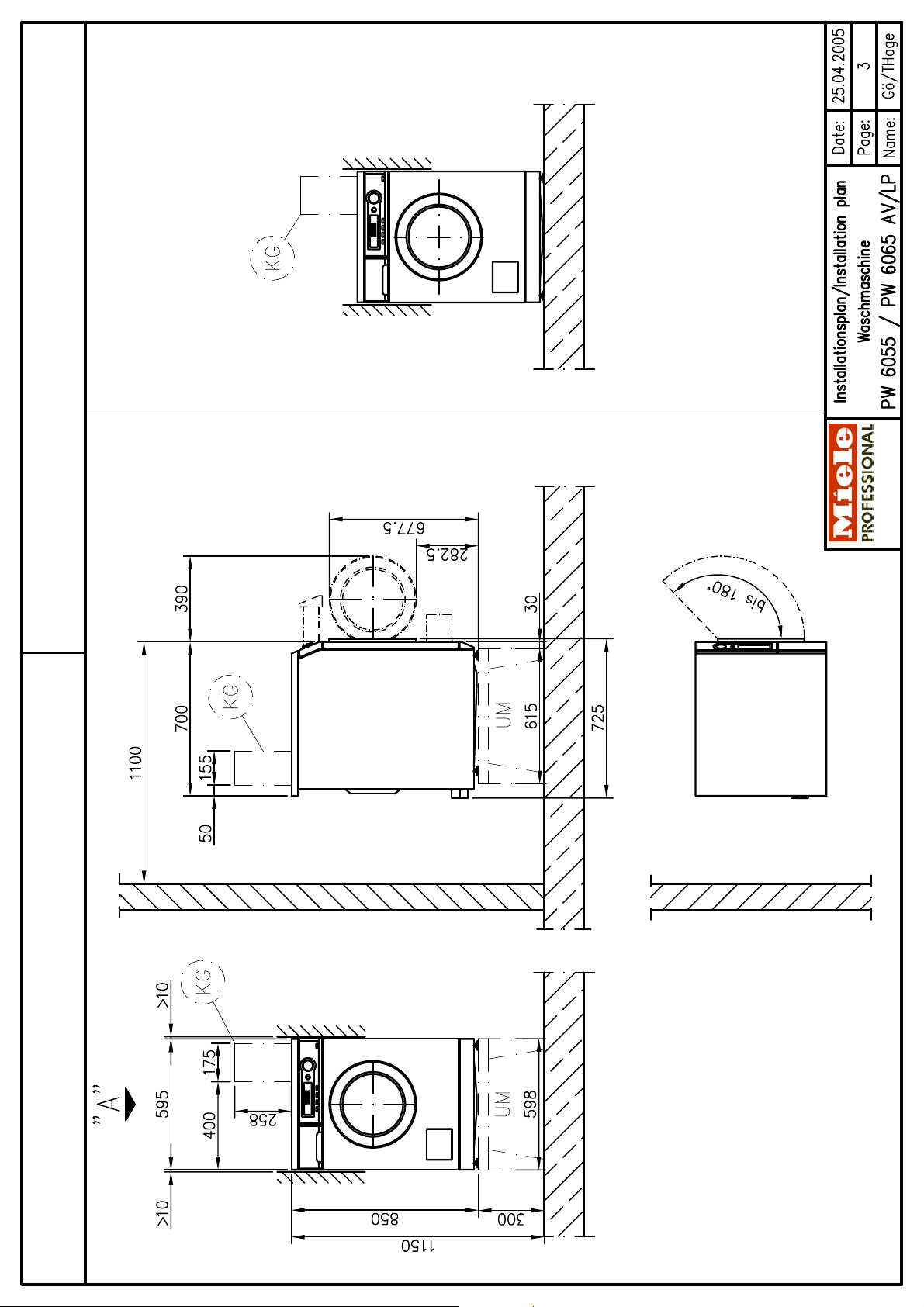
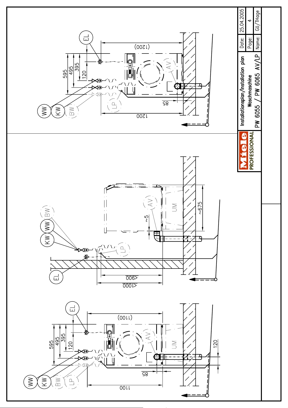
Installationsplan / Installation plan
Installatietekening
Plan d`installation
Piano di installazione
Plano de instalación
Plano de instalação
Σχέδιο εγκατάστασης
Asennusohje
Installasjonsplan
Installationsplan
G
PW 6055 + PW 6065 AV/LP
Materialnummer / Mat. no.: 06 664 230
Änderungsstand / Version: 00
Datum Zeichnung / Drawing date: 25.04.2005
Datum Legende / Legend date: 02.05.2005
Page 2

Page 3
Page 4
Page 5

Page 6

Page 7

Page 8

Technical datasheet
Washer-extractor
Heating:
PW 6055/PW 6065 AV/LP
Electric (EL)
Legend:
Circled, bold-type abbreviations:
Connection required
G
Optional extras:
UM
Height Model mm 300
Width UG (UO) mm 609 (598)
Depth UG (UO) mm 622 (615)
Abbreviations surrounded by broken circle:
Connection optional or required, depending on model
UG/UO 5005 Miele plinth
(UG = Box plinth/UO = Open plinth)
Concrete platform Concrete platform optional (Min. quality B15)
BS
Recommended width mm 600
Recommended depth mm 650
Ensure good anchorage!
Recommended height mm 300
Minimum height mm 70
Machine connections:
connection Frequency Hz 50
Connection cable, min. cross-section mm² 4 × 1.5
Length of supply lead (supplied) mm 2000
Alternative voltage V 1N AC 230
Frequency Hz 50
Rated load kW 2.85
Fuse rating A 1 × 16
Connection cable, min. cross-section mm² 3 × 1.5
Length of supply lead (supplied)
Country variations:
2. Standard voltage (as supplied) V 2N AC 400
Frequency Hz 50
Fuse rating A 2 × 13
Connection cable, min. cross-section mm² 4 × 1.5
Length of supply lead (supplied) mm 2000
Rated load kW 5.5
Fuse rating A 2 × 16
G
1. Standard voltage (as supplied) V 2N AC 400 Electrical
convertible
mm 2000
Rated load kW 5.5
Alternative voltage V 1N AC 230
Frequency Hz 50
Rated load kW 2.85
Fuse rating A 1 × 13
Connection cable, min. cross-section mm² 3 × 1.5
Length of supply lead (supplied)
3. Standard voltage (as supplied) V 1N AC 230
Frequency Hz 50
Fuse rating A 1 × 25
Connection cable, min. cross-section mm² 3 × 2.5
Length of supply lead with plug (supplied) mm 2000
Installationsplan PW 6055/PW 6065 AV/LP EL
Stand: 02.05.2005 Seite 8
Rated load kW 5.5
convertible
mm 2000
Page 9

4. Standard voltage (as supplied) V 3N AC 400
a j
Frequency Hz 50
Rated load kW 4.8
Fuse rating A 3 × 10
Length of supply lead (supplied) mm 2000
S
Connection cable, min. cross-section mm² 5 × 1.5
5. Standard voltage (as supplied) V 2N AC 400
Frequency Hz 50
Rated load kW 5.5
Fuse rating A 2 × 16
Length of supply lead (supplied) mm 2000
Alternative voltage V 1N AC 230
Frequency Hz 50
Rated load kW 2,85
Fuse rating A 1 × 16
Connection cable, min. cross-section mm² 4 × 1.5
Length of supply lead (supplied)
Alternative voltage V 3 AC 230
Frequency Hz 50
Rated load kW 5.5
Fuse rating A 3 × 20
Connection cable, min. cross-section mm² 4 × 2.5
Length of supply lead (not supplied)
6. Standard voltage (as supplied) V 1N AC 230
Frequency Hz 50
Rated load kW 3.2
Fuse rating A 1 × 16
Length of supply lead with plug (supplied) mm 2000
7. Standard voltage (as supplied) V 1N AC 230 - 240
Frequency Hz 50
Rated load kW 5.5 – 6.0
Fuse rating A 1 × 25
Length of supply lead with plug (supplied) mm 2000
B
N
W
Connection cable, min. cross-section mm² 4 × 1.5
convertible
mm 2000
convertible
mm 2000
Connection cable, min. cross-section mm² 3 × 1.5
Connection cable, min. cross-section mm² 3 × 2.5
8. Standard voltage (as supplied) V 2 AC 200
Frequency Hz 50-60
Rated load kW 3.75
Fuse rating A 2 × 20
Length of supply lead with plug (supplied) mm 2000
9. Standard voltage (as supplied) V 2 AC 208
Frequency Hz 60
Rated load kW 3.95
Fuse rating A 2 × 20
Length of supply lead (supplied) mm 2000
1. Standard voltage (as supplied) V 3 AC 230
Frequency Hz 60
Rated load kW 4.4
Fuse rating A 3 × 16
Length of supply lead (supplied) mm 2000
2. Standard voltage (as supplied) V 3 AC 400
Frequency Hz 50
Rated load kW 4.2
Fuse rating A 3 × 16
Length of supply lead (supplied) mm 2000
J
Connection cable, min. cross-section mm² 3 × 2.75
U l
Connection cable, min. cross-section mm² 4 AWG 10
Non-standard voltages:
OS 230
Connection cable, min. cross-section mm² 4 × 1.5
OS 400
Connection cable, min. cross-section mm² 4 × 1.5
Installationsplan PW 6055/PW 6065 AV/LP EL
Stand: 02.05.2005 Seite 9
Page 10

3. Standard voltage (as supplied) V 3 AC 440
Frequency Hz 60
Rated load kW 5.05
Fuse rating A 3 × 16
Length of supply lead (supplied) mm 2000
OS 440
Connection cable, min. cross-section mm² 4 × 1.5
Plug and socket connection in accordance with IEC 60309
Cold water
On-site connection thread according to DIN 44 991 Inch ¾" external thread
Length of connection hose (parts supplied: 1 connection
Standard connection [with hot water connection]
PW 6055 (PW 6065) l/h approx. 36
Additional requirements if hot water supply is not available.
Hot water
Max. throughput l/min 11
On-site connection thread according to DIN 44 991 Inch ¾" external thread
Length of connection hose (parts supplied: 1 connection
Standard connection [with hot water connection]
PW 6055 (PW 6065) l/h approx. 13
In absence of hot water, use blind stopper supplied and
recommended to facilitate electrical safety tests.
Install mains isolator according to IEC 60947 on hard-wired
connection.
Wall socket or mains isolator must be accessible after
installation.
The use of an earth leakage circuit breaker (ELCB) is strongly
recommended. If an ELCB is fitted, it must be a Type B RCD
able to cope with rectified three-phase supplies.
If necessary, equipotential bonding with good galvanic contact
must be provided in accordance with all appropriate national
and local regulations.
Min. flow pressure kPa 100
Max. pressure kPa 1000
Max. throughput (if hot water supply is not available) l/min 10 (11)
hose)
Water requirements (average for 60°C programme)
Max. temperature °C 70
Min. flow pressure kPa 100
Max. pressure kPa 1000
hose)
Water requirements (average for 60°C programme)
reprogramme controls to cold water intake.
mm 1500
mm 1500
Alternative water
supply
Length of connection hose (parts supplied: 1 connection
Standard connection [with hot water connection]
PW 6055 (PW 6065) l/h approx. 14
When using an alternative water supply, the following
(Optional) On-site connection thread according to DIN 44 991 Inch ¾" external thread
Deduction from cold water requirements PW 6055 l/h approx. 4
Deduction from hot water requirements PW 6055 l/h approx. 10
Drainage via
dump valve
Min. flow pressure kPa 100
Max. pressure kPa 1000
Max. throughput (if hot water supply is not available) l/min 11
hose)
Water requirements (average for 60°C programme)
volumes can be deducted from hot or cold water supplies:
Max. temperature °C 70
Machine drain connection (d
On-site drain connection (d
Max. transient throughput l/min 50
Vented drainage required. If ventilation is insufficient, fit Miele
kit, Mat. no. 05238090.
Drain manifolds serving several machines must be of
sufficient cross-section.
× s × l) [DN 70] mm 75 × 1.9 × 40
ext
× s × l) [DN 70 sleeve] mm 75 × 1.9 × 50
int
mm 1500
Installationsplan PW 6055/PW 6065 AV/LP EL
Stand: 02.05.2005 Seite 10
Page 11

Drainage via
drain pump
Max. transient throughput l/min 26
Max. head height (measured from base of unit) mm 1000
Max. temperature °C 70
Drain hose (Int. dia. × wall thickness × l) [DN 22] mm 22 × 6 × 1500
Hose sleeve for drain hose to be provided on site (ext. dia. x l) mm 22 × 30
Vented drainage required. If ventilation is insufficient, fit Miele
kit, Mat. no. 05238090.
Drain manifolds serving several machines must be of
sufficient cross-section.
Fittings (supplied)
4 × rawl plugs (Ø × length) mm 12 × 60
Machine must be secured if installation is on plinth!
Fixing materials for floating screed floor to be provided on site
2 × rawl plugs (Ø × length) mm 8 × 40
Machine must be secured if installation is on plinth!
Fixing materials for floating screed floor to be provided on site
Payment system
Possible
extensions
Liquid dispensing
Connection to serial interface, RS 232
Machine data Width mm 595
Depth mm 700
Height mm 850
Knocked-down dimensions (W × H) mm 600 × 1000
Minimum rear wall gap (measured to front of machine) mm 1100
Net weight PW 6055 (PW 6065) kg 104 (105)
Dynamic floor load, max. N 2820
Max. static load PW 6055 (PW 6065) N 1380 1455
Dynamic load, max. N 1365
Drum frequency, max. Hz 24
Average heat dissipation
Miele plinth UG/UO 5005
4 × metal angled brackets (to secure machine to plinth)
4 × screws DIN 571 (Ø × length) mm 8 × 65
On concrete platform
2 × metal brackets
2 × screws DIN 571 (Ø × length) mm 6 × 50
The following extensions are possible:
Installation of payment system
Installation as washer-dryer stack
W 250
(dependent on ambient room temperature and programme
selected)
Installation should only be carried out by authorised fitters in accordance with valid regulations!
Observe installation instructions when installing machine! All rights reserved! Measurements in mm
Installationsplan PW 6055/PW 6065 AV/LP EL
Stand: 02.05.2005 Seite 11
 Loading...