

Page 1
Installation plan
Washer-extractor
PW 5134 MF
To avoid the risk of accidents or damage to the machine, it is essential to read
operating and installation instructions before installation and commissioning
This prevents you from harm and the machine from damage.
en - GB
09 748 180 / 02
Page 2

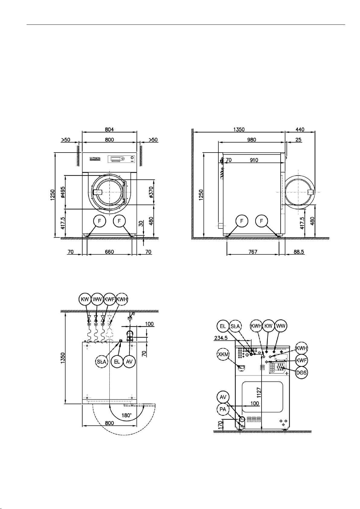
Legend:
Connection required
Connection optional or required,
depending on model
AV
Dump valve
KWH
Cold water (raw water)
B
Machine anchors
OS
Offshore version
BS
Installation on concrete plinth
PA
Equipotential bonding
DOS
Dispenser connection
SLA
Peak-load/energy management
EL
Electrical connection
UG
Box plinth
F
Machine feet, adjustable
UO
Open plinth
KW
Cold water
WW
Hot water
KWF
Cold water liquid dispensing
XKM
Communication module
All rights reserved. 04/14/431
2 09 748 180 / 02
Page 3
PW 5134 en - GB
Machine dimensions PW 5134
09 748 180 / 02 3
Page 4
en - GB PW 5134
Installation PW 5134
4 09 748 180 / 02
Page 5

PW 5134 en - GB
Installation PW 5134
09 748 180 / 02 5
Page 6

en - GB PW 5134
Installation PW 5134
6 09 748 180 / 02
Page 7

PW 5134 en - GB
Technical data
PW 5134 MF
Detergent dispenser (WEK)
-
Load capacity (load ratio 1:25)
kg
13 Drum volume
l
130 Spin speed, max.
rpm
1050 g factor
360
Connection data
Heater rating / Nominal heat load
kW
15 Motor rating - Drive motor
W
2200
Electrical connection (EL)
Standard voltage
3N AC 380-415 V
Frequency
Hz
50 - 60
Total rated load, max.
kW
17 Fuse rating (B trip rating according to EN 60898)
A
3 x 25
Supply lead min. cross-section
mm²
5 x 4
Variations in the following countries:
Standard voltage (N only)
3 AC 220-240 V
Frequency
Hz
50 - 60
Total rated load, max.
kW
17 Fuse rating (B trip rating according to EN 60898)
A
3 x 50
Supply lead min. cross-section
mm²
4 x 10
Cold water, (KW)
Machine connection
Water pressure (flow rate)
kPa
100 - 1000
Recommended flow pressure (for short water intake times)
kPa
300 Flow rate, max.
l/min
16 Flow rate, max. (in absence of on-site water heating)
l/min
32 Average water consumption (60°C in standard mop programme)
l/h
Approx. 205
Connection to be provided on site, external thread according to DIN 44 991
Inch
3/4“
Connection hose 1/2" with 3/4" threaded union
No. 1
Connection hose length
mm
1500
Hot water (WW)
Machine connection
Max. permissible water temperature
°C
70 Water pressure (flow rate)
kPa
100 - 1000
Recommended flow pressure (for short water intake times)
kPa
300 Flow rate, max.
l/min
16 Average water consumption (60°C in standard mop programme)
l/h
Approx. 40
Connection to be provided on site, external thread according to DIN 44 991
Inch
3/4“ Connection hose 1/2" with 3/4" threaded union
No. 1
Connection hose length
mm
1500
Cold raw water (KHW)
Machine connection (separate kit required)
Water pressure (flow rate)
kPa
100 - 1000
Recommended flow pressure (for short water intake times)
kPa
300 Flow rate, max.
l/min
32 Connection to be provided on site, external thread according to DIN 44 991
Inch
1“ Y-piece connector 3/4" to 1"
No. 1
Connection hose 1/2" with 3/4" threaded union
No. 2
Connection hose length
mm
1500
= standard, = optional, + = only on request, - not available
09 748 180 / 02 7
Page 8

en - GB PW 5134
Technical data
PW 5134 MF
Cold water liquid dispensing (KWF)
Machine connection
Water pressure (flow rate)
kPa
100 - 1000
Recommended flow pressure (for short water intake times)
kPa
300 Flow rate, max.
l/min
5.5 Connection to be provided on site, external thread according to DIN 44 991
Inch
3/4“ Connection hose 1/2" with 3/4" threaded union
No. 1
Connection hose length
mm
1500
Dump valve (AV)
Machine connection
Max. drainage temperature
°C
95 Connection (ext. diameter)
mm
75 (DN 70)
Sleeve connection to be provided on site (int. diameter)
mm
75 (DN 70)
Max. transient flow rate
l/min
200
Equipotential bonding (PA)
Machine connection
Bolt hole (diameter)
mm
10
Peak load/energy management (SLA)
Machine connection
Control signal voltage
AC 230 V
Recommended supply lead cross-section
mm²
5 x 1.5
Communication module (XKM)
Communication module slot
Communication module for serial connection (XKM RS 232)
Dispenser connection (DOS)
Connection for 1 - 10 liquid products
Connection for 2 paste-type products
Hose connection for liquid dispensing, cross-section
mm
6 / 8 / 12
Hose connection for dispensing of paste-type products, cross-section
mm
12
Dispenser pumps
Connections of 1 - 6 dispenser pumps
Connection of electrical dispenser pumps 7 - 12 (optional kit)
Dispenser pump connection voltage
Connections for 'Container empty' and dispensing signals
Alternative flowmeter connection for monitoring dispensing
Installation on machine feet (F)
No. of machine feet
No. 4
Machine foot, height-adjustable with thread
mm
±10 Machine foot diameter
mm
25
Anchoring (B)
Standard anchoring
Anchor kit using angled brackets (from transport lock)
Required anchor points
No. 2
Wood screws according to DIN 571
mm
8 x 80
Rawl plugs (diameter x length)
mm
12 x 60
Anchoring of Miele plinths
Accessory: Miele plinth (fasteners included)
Required anchor points
No. 4
Wood screws according to DIN 571
mm
8 x 80
Rawl plugs (diameter x length)
mm
12 x 60
= standard, = optional, + = only on request, - not available
8 09 748 180 / 02
Page 9

PW 5134 en - GB
Technical data
PW 5134 MF
Plinth floor anchoring (to be provided on site)
Machine installation on on-site plinth (concrete or masonry)
Plinth installation footprint (W/D)
mm
950/1000
Required anchor points
No. 2
Wood screws according to DIN 571
mm
8 x 80
Rawl plugs (diameter x length)
mm
12 x 60
Machine data
Sound emissions and floor load
Transport weight (incl. packaging)
kg
360 Machine weight (net weight)
kg
340 Max. static floor load
N
3778 Max dynamic floor load
N
503 Max. floor load in operation
N
4290 Drum frequency
Hz
18.3
Site-access dimensions
Min. site-access (H/W)
mm
1300/820
Unit dimensions
Overall machine dimensions (H/W/D):
mm
1250/804/1005
Stripped-down machine dimensions(H/W/D)
mm
1250/800/910
Installation dimensions
Min. side gap
mm
50
Recommended distance to opposite wall from front of machine
mm
1350 Min. wall gap to machine lid
mm
400
Emissions
Sound pressure level: in accordance with EN ISO 11204, workplace-related
dB(A)
69 Sound power level (A) according to EN ISO 9614 Part 2
dB(A)
< 80 Heat dissipation rate to installation site
W
1470
Options / Accessories
Features
Box plinth (UG)
Box plinth, H 150 mm (UG 6013)
Galvanised plinth, stainless-steel front, octoblue side panels
Box plinth, H 300 mm (UG 6013-30)
Galvanised plinth, stainless-steel front, octoblue side panels
Open plinth (UO)
Open plinth, H 150 mm (UO 6013)
Galvanised plinth, octoblue stove finish
Open plinth, H 300 mm (UO 6013-30)
Galvanised plinth, octoblue stove finish
Communication module (XKM)
Communication module for serial connection (XKM RS 232)
Plug-in module with cable and Sub-D plug, 9-pole
Fluff filter box (FFK)
Fluff filter box, standalone (FFK01)
Stainless-steel fluff filter box, perforated stainless-steel filter, DN70 connection
Accessories
Water recycling (WRG02)
Water recovery module
Vapour and foam venting kit (BWS01)
Kit to discharge steam and foam from machine
Kit: Raw water (BSH)
Kit containing additional inlet valves for raw (untreated) water
Flowmeter (FRZ01)
Operating data acquisition kit for recording water volumes
Connection for payment system (BSK)
Connection of single-machine coin mechanisms
Connection of peak-load/energy management (BSS)
Connection for peak-load and energy management functionalities
= standard, = optional, + = only on request, - not available
09 748 180 / 02 9
Page 10

en - GB PW 5134
Installation and planning notes
Installation requirements:
The electrical connection may only be made to a power network
provided in accordance with all appropriate local and national
legislation and regulations.
In addition, all regulations issued by the appropriate utilities as well as
standards relating to occupational safety, and all applicable valid
regulations and technical standards must be observed!
The machine should only be commissioned, serviced and
maintained by a Miele authorised and trained service technician
only.
Transportation and site access
The machine must not be moved without the transit bars in place.
Keep the strut in a safe place. They must be re-fitted if the machine is
to be moved again (e.g. when moving house).
General operating conditions
Ambient temperature in installation room: 15°C - 40°C
Relative humidity: 10% - 85%
Depending on the nature of the installation site, sound emissions and
vibration may occur.
Miele recommends consulting a specialist if particular requirements
apply at the installation site with respect to sound emissions.
Electrical connection
Electrical connection is the responsibility of a qualified electrician.
Take note of the rated loads on the machine and in the enclosed
wiring diagram.
The machine can be hard-wired or connected using a switched
connection in accordance with IEC 60309-1. The wall socket or switch
must be accessible after installation.
It is always recommended to make electrical connection via a plug
and socket so that electrical safety checks, e.g. during repair or
service work, can be carried out easily.
If the machine is disconnected from the electricity supply ensure
adequate measures are taken to ensure that the machine cannot be
reconnected to the electricity supply until all work has been carried
out.
If an earth leakage circuit breaker (ELCB) is required by local
regulations, a Type B earth leakage circuit breaker (AC/DCsensitive) should be used.
A supply lead is not supplied with the machine and must be provided
on site.
References to cable cross-sections in the technical data refer only to
the required supply lead. Please consult relevant local and national
regulations when calculating any other wire gauges.
Cold water connection
Connection to the water supply should be carried out by a qualified
plumber and should incorporate a tap with a threaded union. If not
available, a qualified plumber should connect the machine to the
water supply.
The machine can be connected to a potable water supply without a
non-return valve as the machine is designed according to the latest
standards to protect drinking water.
The machine must be connected to the water supply using the inlet
hoses provided.
Connection using 2 inlet hoses
A Y-piece is supplied with the machine.
Hot water connection
The same connection requirements as for cold water also apply to hot
water (max. 70°C).
The hot water supply must not exceed the maximum temperature.
In the event that hot water is not available on site, connection of the
second hose must be made to a cold water supply.
The required amount of hot water should be added to the cold water
volume.
Cold water (raw water)
The connection of an optional type of water is optional and requires
the use of an additional kit.
The same requirements apply as for the cold water connection.
Cold water liquid dispensing
The connection for an additional inlet hose is either provided on the
machine or can be retrofitted using an additional kit when connecting
a liquid dispensing system.
The additional cold water intake flushes the contents of the dispenser
into the drum and prevents any carryover of detergent.
The same requirements apply as for the cold water connection.
Equipotential bonding
If necessary, equipotential bonding with good galvanic contact must
be guaranteed in compliance with all applicable local and national
installation specifications.
Equipotential bonding must have an earth current rating >10 mA.
Connection material for equipotential bonding must be provided on
site.
10 09 748 180 / 02
Page 11

PW 5134 en - GB
Peak load/energy management
The machine can be connected to a peak-load or energy
management system using an optional kit.
Three signals are issued by the machine via a terminal strip. The
terminal strip is labelled a, b, c, and d.
a - Output signal, Start of machine operation
b - Output signal, Machine heating request
c - Peak-load input signal, Machine heating deactivated
d - Neutral conductor
When a peak-load signal is received, the heating is deactivated and
the programme stopped. An appropriate message appears in the
display.
The programme is resumed automatically when the peak-load system
reactivates the heating.
Dispenser connection
Depending on the model, up to 12 products can be dispensed.
It is particularly important to observe manufacturer's instructions
when using a combination of detergents, additives and specialpurpose products.
Connection of dispenser to mixer box
Dump valve
Machine drainage is effected by a pinch valve which is operated by
the pressure of the water supply.
The machine can be connected directly to the on-site drainage system
(without an odour trap) or via a floor drain (with odour trap).
A vented drainage system is vital for unimpeded drainage. If on-site
venting is insufficient, a vent kit (Mat. no. 05239540) is available from
Miele Spares or authorised dealers.
If several machines are connected to a single drain pipe, this should
be sufficiently large to allow all machines to drain simultaneously.
Slow or obstructed drainage or a backlog of water in the drum as a
result of undersized pipework can result in faults occurring during
programmes which will result in error messages appearing in the
display.
Installation and anchoring
The machine must be installed on a perfectly smooth, level and firm
surface which is able to withstand the quoted loads.
The machine should be levelled in both directions with the aid of the
adjustable feet.
The floor load created by the machine is concentrated and transferred
to the installation footprint via the machine feet.
It is absolutely necessary to bolt the machine to the floor.
The angled brackets provided can be used to anchor the machine.
The material provided is intended to bolt the machine to a concrete
floor.
Bolts and fasteners for all other floor types must be provided on site.
The gaps between the machine and adjacent walls are to be
construed as minimum requirements. Side gaps must be observed to
allow for the dynamic movement of machines.
Connections 1 and 2 are provided for viscous agents. These
connections are sealed and need to be drilled open using a drill bit.
Water connections for liquid dispensing connections 3 to 12 are for
liquid dispensing. These connections are sealed and must be cut to
suit the diameter of the hose with a suitable hacksaw.
If opened connections are no longer required, they must be resealed.
Feed pumps can be connected directly inside the machine for
dispensing. The machine's electronic controls monitor dispensing and
the calibration of the dispenser pumps.
Alternatively, flowmeters can be connected to provide greater
dispensing accuracy.
'Container empty' signals are provided to ensure that sufficient
volumes of dispensed products are available during external
dispensing. A message appears in the display when a container is
empty.
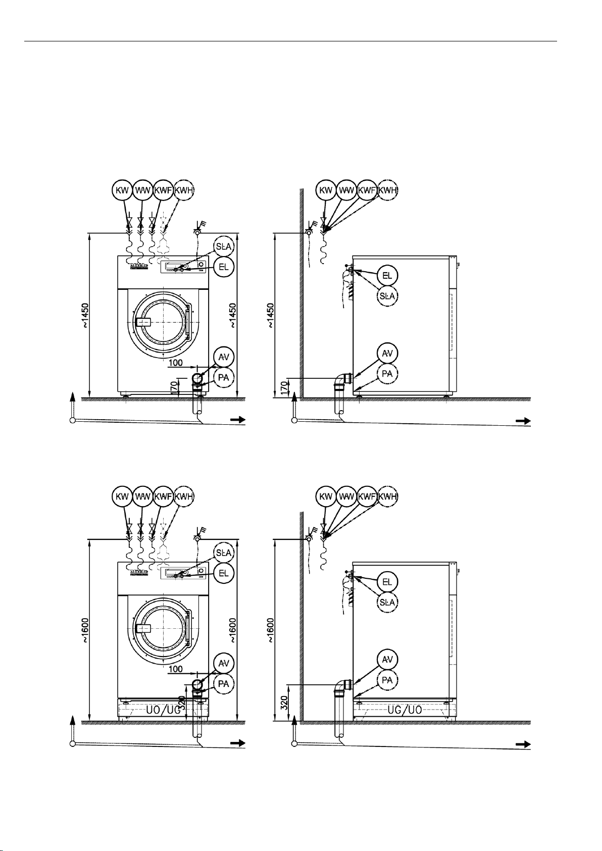
Plinth installation
The machine can be installed on a machine plinth (open or box plinth,
available as an optional Miele accessory) or on a concrete plinth to be
provided on site.
The quality of the concrete and its strength must be assessed
according to the machine load. Ensure that any raised concrete plinth
is adequately bonded to the concrete floor below!
09 748 180 / 02 11
 Loading...