

查询SY88822V供应商
Micrel
5V/3.3V 155Mbps
LASER DIODE DRIVER
WITH OUTPUT ENABLE
SY88822V
SY88822V
FEATURES
■ Single 3.3V or 5V power supply
■ Up to 155Mbps operation
■ Modulation current to 30mA
■ PECL output enable
■ Differential PECL inputs
■ Available in a tiny 10-pin (3mm) MSOP
APPLICATIONS
■ 155Mbps SONET
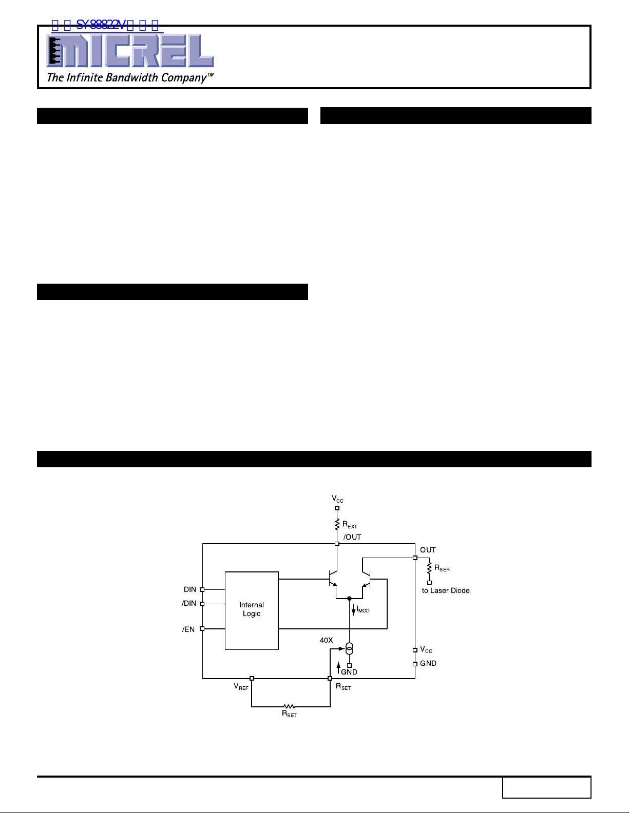
DESCRIPTION
The SY88822V is a high speed current switch for driving
a semiconductor laser diode in optical transmission
applications. The modulation current (I
the current (I
) through the external resistor R
RSET
output OUT is HIGH and no current flows through OUT
when output enable is HIGH.
The device incorporates complementary open collector
outputs with a 30mA maximum current driving capability.
The external resistor R
must be placed between /OUT
EXT
and VCC to dissipate the worst case power. R
recommended to compensate for laser diode matching
issues. Pin 9 and pin 10 should be connected to achieve
better performance.
The SY88822V utilizes the high performance bipolar
ASSET™ technology.
) is controlled by
OUT
SET
. The
SER
is
FUNCTIONAL BLOCK DIAGRAM
DIN
/DIN
/EN
Internal
Logic
V
REF
V
CC
R
EXT
/OUT
OUT
R
SER
to Laser Diode
I
MOD
40X
GND
R
SET
R
SET
V
CC
GND
ASSET is a trademark of Micrel, Inc.
Rev.: A Amendment: /0
1
Issue Date: March 2003
Micrel
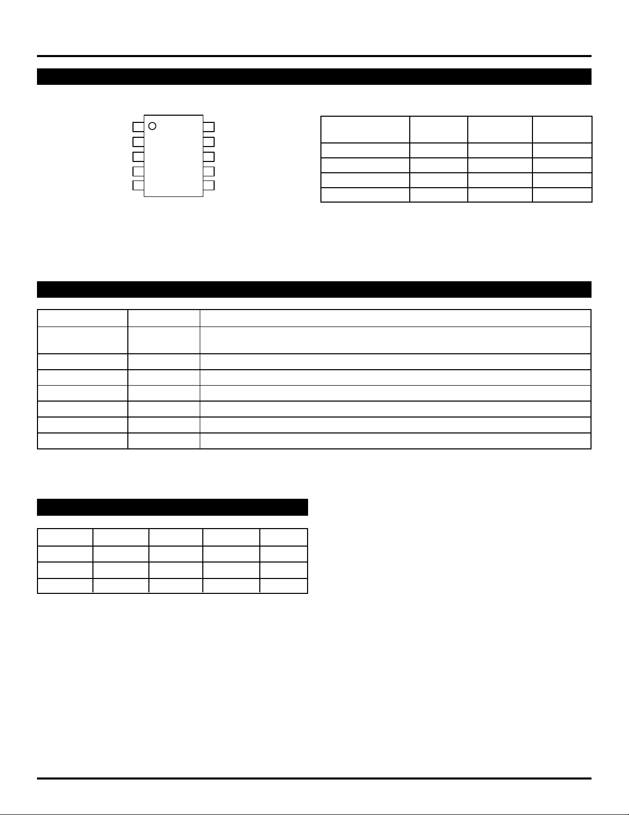
PACKAGE/ORDERING INFORMATION
SY88822V
Ordering Information
Package Operating Package
DIN
/DIN
VREF
RSET VCC65
1/EN
2
3
4
10 OUT
OUT
9
/OUT
8
GND
7
Part Number Type Range Marking
SY88822VKC K10-1 Commercial 822V
SY88822VKCTR* K10-1 Commercial 822V
SY88822VKI K10-1 Industrial 822V
SY88822VKITR* K10-1 Industrial 822V
10-Pin MSOP
*Tape and Reel
(K10-1)
PIN DESCRIPTION
Pin Number Pin Name Pin Function
1 /EN 100k PECL compatible input w/ 75kΩ pulldown resistor. Modulation current goes to zero
when deasserted high.
2, 3 DIN, /DIN Differential 100k PECL compatible input w/ 75kΩ pulldown resistors.
4 VREF Voltage reference for use with R
5 RSET An external resistor from here to V
6 VCC Positive power supply.
7 GND Device ground.
8, 9, 10 /OUT, OUT Differential open collector current outputs.
.
SET
sets the reference current for I
REF
OUT
.
TRUTH TABLE
D /D /EN OUT
(Note1)
(Note 2)
/OUT
LHLHL
HLLLH
XXHHL
Note 1. L = LOW, H = HIGH, X = don't care.
Note 2. H = I
OUT
= 0mA.
2

Micrel
SY88822V
Absolute Maximum Ratings
(Note 1)
Power Supply Voltage (VCC)............................ 0V to +7.0V
Input Voltage (VIN) .............................................. 0V to V
Output Current (I
).................................................30mA
OUT
CC
Power Dissipation (PD) ...........................................250mW
Storage Temperature Range (TS)............–55°C to +125°C
Operating Ratings
Supply Voltage (VIN) ................................... +3.0V to +3.6V
........................................................ or +4.5V to +5.5V
Ambient Temperature (TA), Note 5 ............–40°C to +85°C
Junction Temperature (TJ), Note 5 ............ –40°C to 100°C
Resistor to Dissipate Power (R
Laser Diode Serial Resistor (R
Resistor to Adjust Current (R
(Notes 2, 3, 4)
) ..................10Ω to 50Ω
EXT
) ....................0Ω to 50Ω
SER
), Note 6
SET
......................................................... 700Ω to 20,000Ω
Package Thermal Resistance
MSOP
(θJA) Still-Air ......................................................113°C/W
(ψJB) Still-Air........................................................74°C/W
Note 1. Permanent device damage may occur if ABSOLUTE MAXIMUM RATINGS are exceeded. This is a stress rating only and functional operation
Note 2. The data sheet limits are not guaranteed if the device is operated beyond the operating ratings.
Note 3. The device is guaranteed to meet the DC specifications, shown in the table above, after thermal equilibrium has been established. The device
Note 4. The voltage drop across R
Note 5. Commercial devices are guaranteed from 0°C to +85°C ambient temperature.
Note 6. R
is not implied at conditions other than those detailed in the operational sections of this data sheet. Exposure to ABSOLUTE MAXIMUM
RATlNG conditions for extended periods may affect device reliability.
is tested in a socket such that transverse airflow of ≥500lfpm is maintained.
minimum 430Ω.
SET
EXT
and R
plus Laser Diode must not be greater than 1.4V.
SER
DC ELECTRICAL CHARACTERISTICS
(Note 1)
GND = 0V; VCC = 3.3V ±10% or VCC = 5.0V ±10%; TA = –40°C to +85°C
Symbol Parameter Condition Min Typ Max Units
V
V
V
I
IH
IL
REF
IL
Input HIGH Voltage
VCC–1.165 VCC–0.880
(DIN, /DIN, /EN)
Input LOW Voltage
VCC–1.810 VCC–1.475
(DIN, /DIN, /EN)
Reference Voltage 1.7 2.0 2.3 V
Input LOW Current VI = V
IL(min)
0.5 µA
V
V
(DIN, /DIN, /EN)
I
IH
I
CC
I
OUT_OFF
Input HIGH Current 100 µA
(DIN, /DIN, /EN)
Supply Current I
= 25mA 25 mA
MOD
Output LOW Current 450 1000 µA
(/EN = HIGH)
I
OUT
A
RSET
V
OUT
C
OUT
Note 1. Specification for packaged product only.
Modulation Current 30 mA
I
OUT/IRSET
Voltage at OUT, /OUT
30 38 44 —
VCC–1.4 V
CC
V
Capacitance on OUT, /OUT 2.5 pF
3

Micrel
SY88822V
AC ELECTRICAL CHARACTERISTICS
I
=10mA; GND = 0V; VCC = 3.3V ±10% or VCC = 5.0V ±10%; TA = –40°C to +85°C
MOD
(Note 1, 2)
Symbol Parameter Condition Min Typ Max Units
t
PHL, tPLH
t
PHL, tPLH
D Propagation Delay I
DIN – OUT
EN Propagation Delay I
= 10mA 1000 ps
OUT
= 10mA 1000 ps
OUT
/EN – OUT
t
, t
r
f
Rise/Fall Time 1000 ps
(20% to 80%)
I
OR
Note 1. Specification for packaged product only.
Note 1. R
Output Current Ringing I
= R
EXT
= 25Ω ±1%; R
SER
connected directly to VCC.
SER
= 5 to 30mA 10 %
OUT
TYPICAL OPERATING CHARACTERISTICS
40
30
(mA)
20
MOD
I
VCC = 3.3V
10
0
0.0 1.0 2.0 3.0 4.0 5.0
I
MOD
VCC = 5.0V
RSET (kΩ)
vs. R
SET
4

Micrel
10 LEAD MSOP (K10-1)
SY88822V
Rev. 00
MICREL, INC. 1849 FORTUNE DRIVE SAN JOSE, CA 95131 USA
The information furnished by Micrel in this datasheet is believed to be accurate and reliable. However, no responsibility is assumed by Micrel for its use.
Micrel reserves the right to change circuitry and specifications at any time without notification to the customer.
TEL + 1 (408) 944-0800 FAX + 1 (408) 944-0970 WEB http://www.micrel.com
Micrel Products are not designed or authorized for use as components in life support appliances, devices or systems where malfunction of a product can
reasonably be expected to result in personal injury. Life support devices or systems are devices or systems that (a) are intended for surgical implant into
the body or (b) support or sustain life, and whose failure to perform can be reasonably expected to result in a significant injury to the user. A Purchaser’s
use or sale of Micrel Products for use in life support appliances, devices or systems is at Purchaser’s own risk and Purchaser agrees to fully indemnify
Micrel for any damages resulting from such use or sale.
© 2003 Micrel, Incorporated.
5
 Loading...