

Page 1
CH-9101 Herisau/Switzerland
Tel. ++41 71 353 85 85
Fax ++41 71 353 89 01
Internet www.metrohm.ch
E-Mail info@metrohm.ch
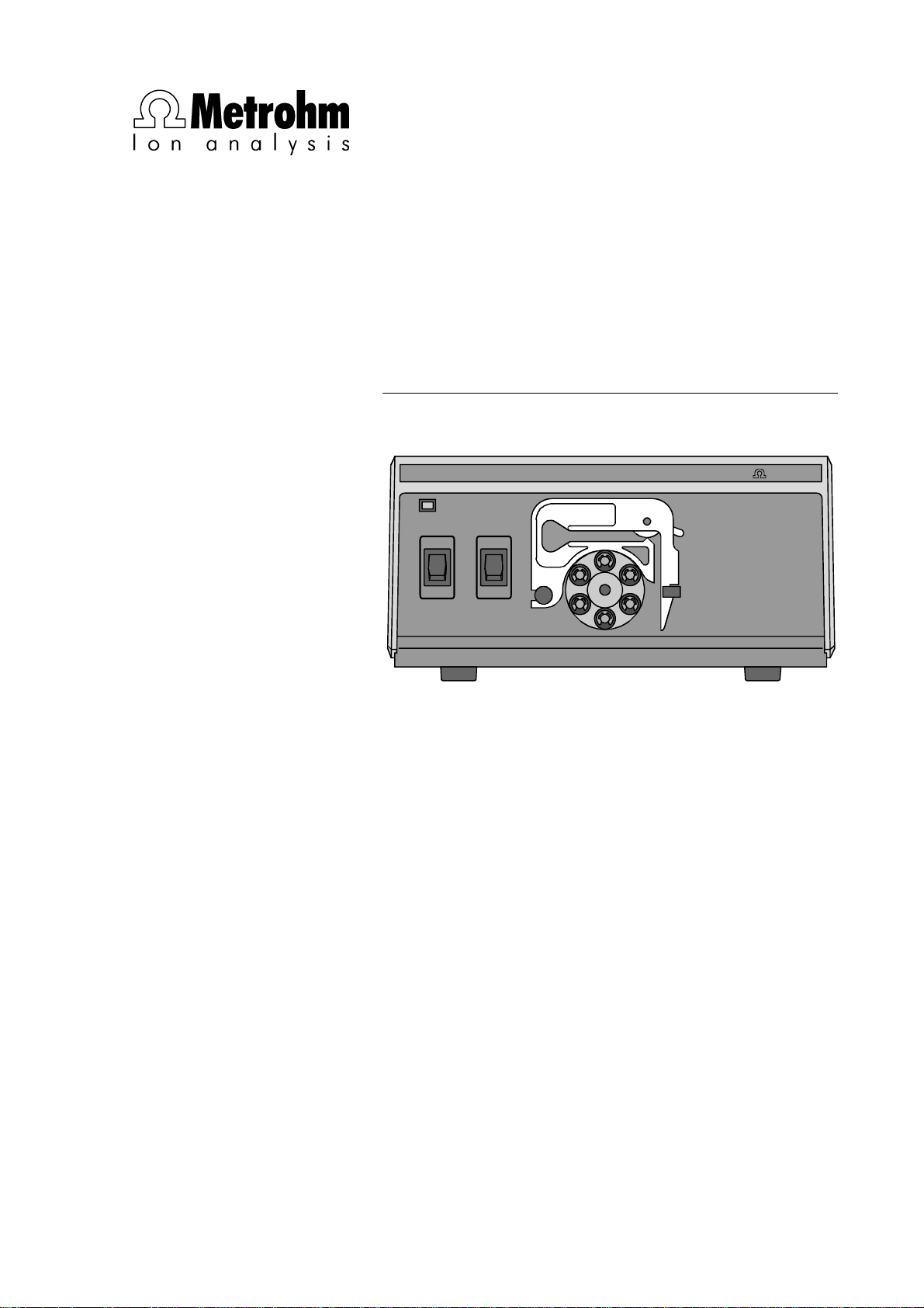
752 Pump Unit
Pump Unit752
POWER
REMOTE PUMP
ON ON
OFFOFF
MetrohmMetrohm
8.752.1013 Instructions for Use
1.10.1998 / dö
Page 2

Table of contents
Table of contents
1 Introduction............................................................................................1
1.1 Instrument description.............................................................................1
1.2 Parts and controls..................................................................................... 2
1.3 Information about the Instructions for Use..........................................4
1.3.1 Organization ..................................................................................4
1.3.2 Notation and pictograms............................................................... 5
1.4 Safety notes ...............................................................................................6
1.4.1 Electrical safety..............................................................................6
1.4.2 General precautionary rules.......................................................... 6
2 Installation..............................................................................................7
2.1 Setting up the instrument........................................................................ 7
2.1.1 Packaging......................................................................................7
2.1.2 Check ............................................................................................7
2.1.3 Location......................................................................................... 7
2.1.4 Arrangement of the instruments....................................................7
2.2 Mains connection......................................................................................8
2.2.1 Setting the mains voltage..............................................................8
2.2.2 Fuses.............................................................................................9
2.2.3 Mains cable and mains connection ..............................................9
2.2.4 Switching the instrument on/off..................................................... 9
2.3 Connection to the IC System ................................................................10
2.3.1 Electrical connection to the 732 IC Detector............................... 10
2.3.2 Connection of the suppressor module .......................................10
3 Operation................................................................................................15
3.1 Manual Operation....................................................................................15
3.2 Operation via 732 IC Detector...............................................................15
4 Troubleshooting.............................................................................17
4.1 Insufficient or non-existing flow rate...................................................17
4.2 Leaking of tubing nipples......................................................................17
4.3 Air bubbles in pump circuit...................................................................18
4.4 Exchanging the pump tubing................................................................18
5 Appendix..................................................................................................19
5.1 Technical data..........................................................................................19
5.2 Standard equipment ...............................................................................21
5.3 Optional accessories..............................................................................21
5.4 Warranty and conformity.......................................................................22
5.4.1 Warranty ......................................................................................22
5.4.2 EU Declaration of conformity ......................................................23
5.4.3 Certificate of conformity and system validation .......................... 24
5.5 Index..........................................................................................................25
752 Pump Unit I
Page 3

Table of contents
List of figures
Fig. 1: Front of the 752 Pump Unit ............................................................................... 2
Fig. 2: Rear of the 752 Pump Unit................................................................................ 3
Fig. 3: Setting the mains voltage.................................................................................. 9
Fig. 4: Connection 752 Pump Unit – 732 IC Detector................................................ 10
Fig. 5: Connections at suppressor module................................................................ 11
Fig. 6: Installing pump tubings................................................................................... 12
752 Pump UnitII
Page 4

1 Introduction
1.1 Instrument description
The 752 Pump Unit is a 2-channel peristaltic pump which can be used
to pump two solutions simultaneously. It is particularly suitable for operating the suppressor module in the 2.733.0X30 IC Separation Center
by supplying regeneration and rinsing solutions. This application is described in detail in these Instructions for Use.
The 752 Pump Unit can either be operated manually by means of the
on/off switch for the pump or remotely controlled via the remote interface.
1.1 Instrument description
752 Pump Unit 1
Page 5
1 Introduction
1.2 Parts and controls
33 44 55
Pump Unit752
POWER
REMOTE PUMP
ON ON
OFFOFF
22 11 668899 77
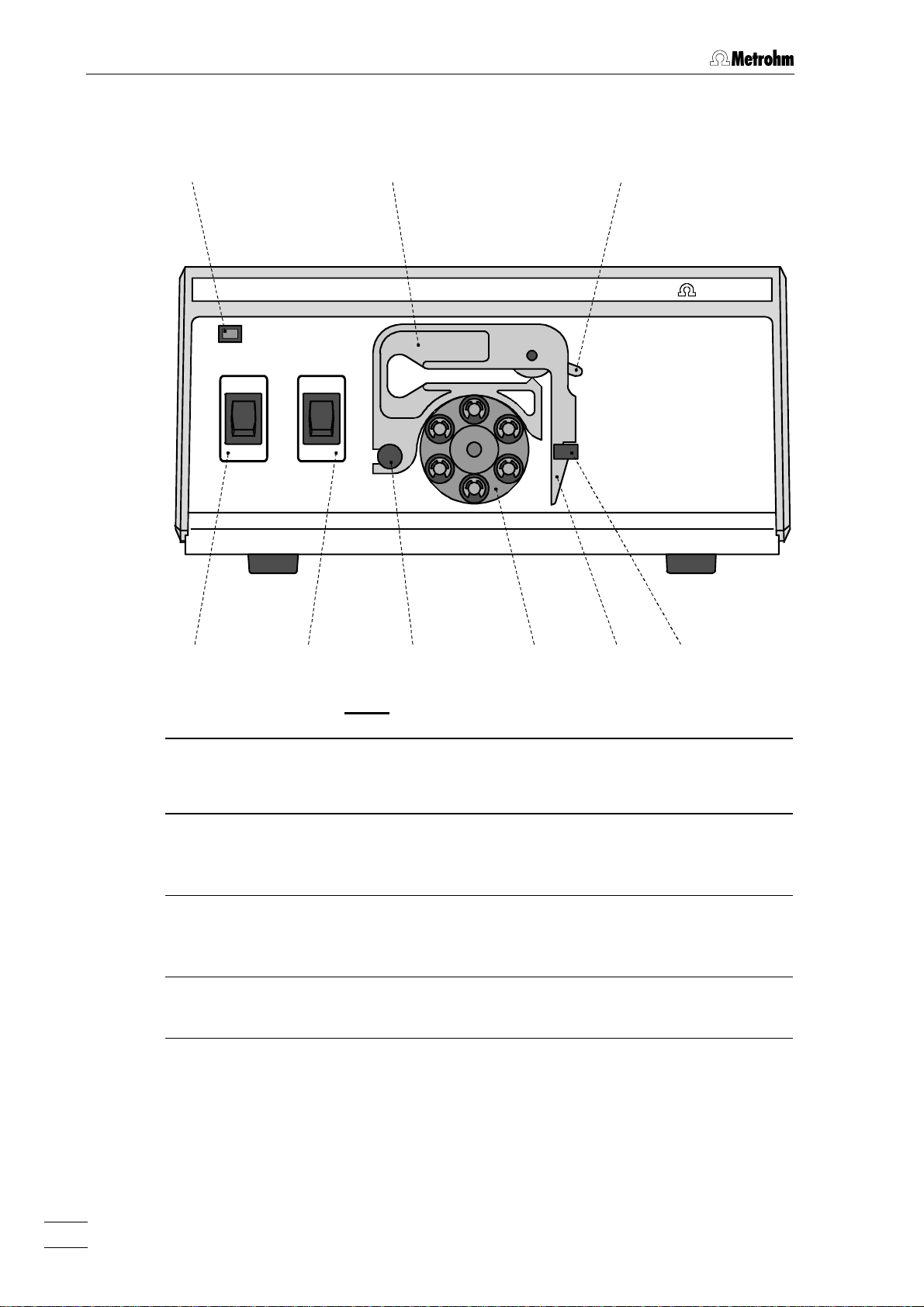
Fig. 1: Front of the 752 Pump Unit
MetrohmMetrohm
11 Pump ON/OFF
On/Off switch for the pump
(manual operation mode)
22 Remote ON/OFF
On/Off switch for remote control
via remote interface
33 Power on lamp
Lights up when instrument is
switched on
44 Tubing cartridge
For 6.1826.050 Pump tubing
55 Contact pressure lever
For adjusting the contact pressure
66 Holding clamp
For locking the tubing cartridge into
place
77 Snap-action lever
For releasing the tubing cartridge
88 Pump drive
Roller head with contact rollers
99 Mounting pin
For attaching the tubing cartridge
752 Pump Unit2
Page 6
1.2 Parts and controls
1010
WARNING - Fire Hazard -
For continued protection replace only
with the same type and rating of fuse
f=50-60 Hz
S=12 VA
115V: 110-120V:
230V: 220-240V:
Type 1.752.0010 Nr.
Fuse
0,2A(T)
0,1A(T)
S
131312121111
Remote
Pump
Made by Metrohm Herisau Switzerland
1515 1414
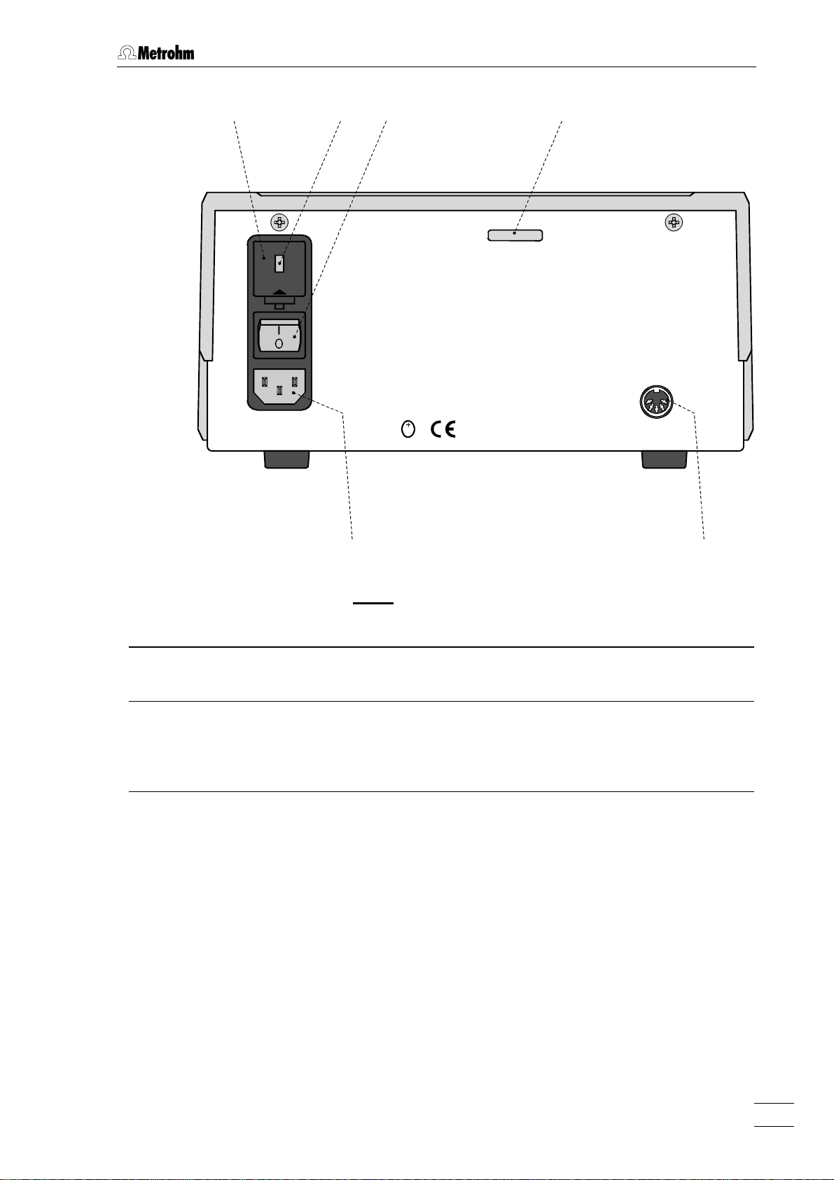
Fig. 2: Rear of the 752 Pump Unit
1010 Fuse holder
Changing the fuses, see section 2.2
1111 Voltage selection insert with
display of voltage
1212 Mains switch
For switching the instrument on/off:
I = ON 0 = OFF
1313 Serial number
1414 Remote interface
Remote I/O lines for connection of
external devices (e.g. 732 IC Detector)
1515 Mains connection plug
Mains connection, see section 2.2
752 Pump Unit 3
Page 7

1 Introduction
1.3 Information about the Instructions for Use
Please read through these Instructions for Use carefully before you put
the 752 Pump Unit into operation. The Instructions for Use contain
information and warnings to which the user must pay attention in order
to assure safe operation of the instruments.
1.3.1 Organization
These 8.752.1013 Instructions for Use for the 752 Pump Unit provide
a comprehensive overview of the startup procedure, operation, fault
rectification and technical specifications of these instruments. The Instructions for Use are organized as follows:
Section 1 Introduction
General description of instruments, parts and controls
and safety notes
Section 2 Installation
Attachment of accessories, connection to IC system
Section 3 Operation
Manual operation and operation via 732 IC Detector
Section 4 Maintenance – Faults
Maintenance, fault rectification
Section5 Appendix
Technical data, standard equipment, options, warranty,
declarations of conformity, index
To find the required information on the instruments please use either
the Table of contents or the Index at the back.
752 Pump Unit4
Page 8
1.3.2 Notation and pictograms
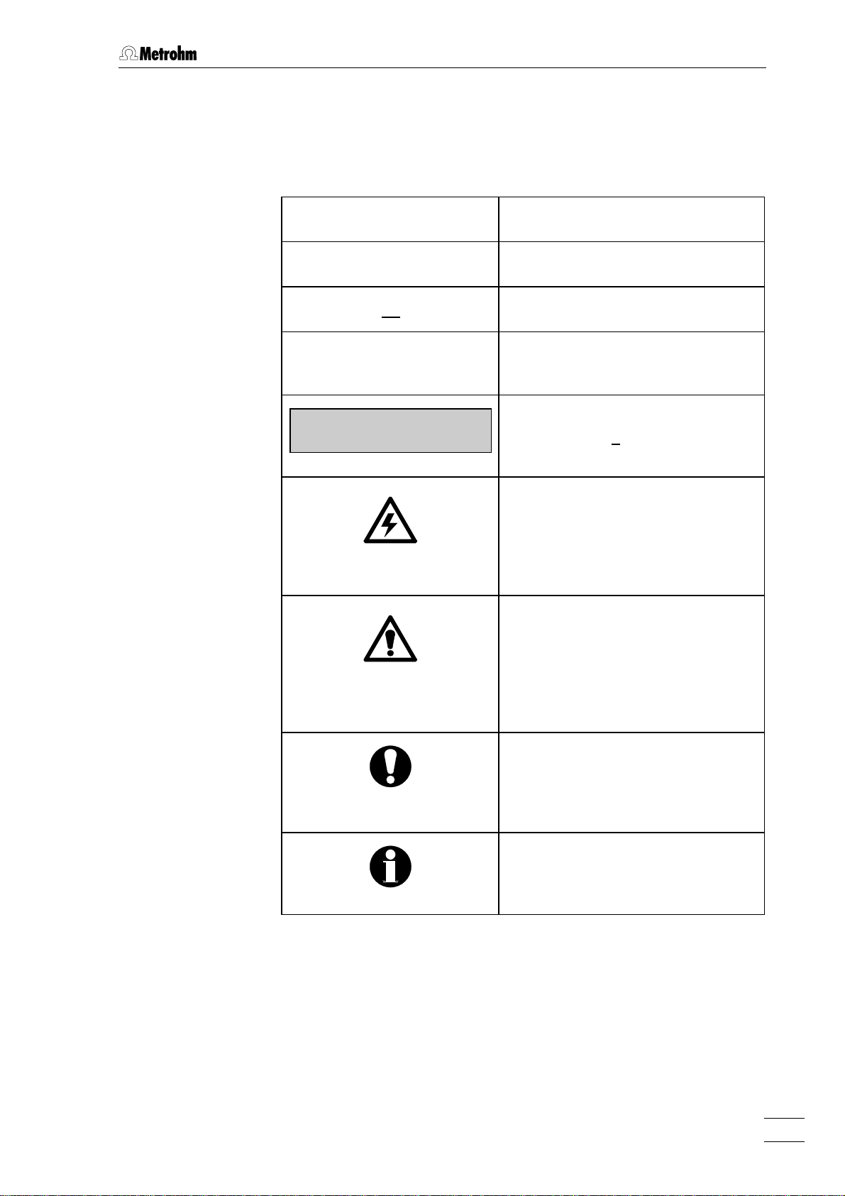
The following notations and pictograms (symbols) are used in these Instructions for Use:
<PUMP> Switch or key
1515 Part or control of 752
8989 Part or control of 732/733
"range" Parameter or entry value
1.3 Information about the Instructions for Use
at 732 IC Detector
>PARAM/detector
range: 1.00 mS/cm
Display
Text in display 11 of the 732 IC
Detector
Hazard
This symbol draws attention to a
possible danger to life or of injury if
the associated directions are not
followed correctly.
Warning
This symbol draws attention to
possible damage to instruments or
instrument parts if the associated
directions are not followed correctly.
Caution
This symbol marks important information. First read the associated
directions before you continue.
Comment
This symbol marks additional information and tips.
752 Pump Unit 5
Page 9
1 Introduction
1.4 Safety notes
1.4.1 Electrical safety
While electrical safety in the handling of the 752 Pump Unit is assured
in the context of the specifications IEC 1010-1 (protection class 1, degree of protection IP40), the following points should be noted:
• Mains connection
Setting the mains voltage, checking the mains fuse and the mains
connection must be effected in accordance with the instructions in
section 2.2.
• Opening the 752 Pump Unit
When the 752 Pump Unit is connected to the power supply the instrument must neither be opened nor should parts be removed from
it, otherwise there is a danger of coming into contact with components which are live. Always disconnect the instrument from all voltage
sources before you open it and ensure that the mains cable is
disconnected from mains connection 1515 !
• Protection against static charges
Electronic components are sensitive to static charging and can be
destroyed by discharges. Before you touch any of the components
inside the 752 Pump Unit, you should earth yourself and any tools you
are using by touching an earthed object (e.g. housing of the instrument or a radiator) to eliminate any static charges which exist.
1.4.2 General precautionary rules
• Handling of solvents
Check all pump tubings and all input and output lines periodically for
possible leaks. Follow the relevant instructions regarding the handling
of flammable and/or toxic solvents and their disposal.
• Regular exchange of pump tubings
Pump tubings are consumable material and must be replaced from
time to time (see section 4.4). Suitable measures must be taken so
that any leak which might occur in the pump tubing or connections
during unattended operation will cause no damage (placing the
instrument at the bottom, collection device for any liquid which may
leak out).
752 Pump Unit6
Page 10

2 Installation
2.1 Setting up the instrument
2.1.1 Packaging
The 752 Pump Unit is supplied together with the separately packed
accessories in special packagings containing shock-absorbing foam
linings designed to provide excellent protection. The actual instrument
is packed in an evacuated polyethylene bag to prevent the ingress of
dust. Please store all these special packagings as only they can assure
damage-free transport of the instrument.
2.1.2 Check
2.1 Setting up the instrument
After receipt, immediately check whether the shipment is complete and
has arrived without damage (compare with delivery note and list of
accessories in section 5.2). In the case of transport damage, see
instructions in section 5.4.1 "Warranty".
2.1.3 Location
Position the instruments in the laboratory at a location convenient for
operation, free from vibrations and protected against a corrosive
atmosphere and contamination by chemicals.
2.1.4 Arrangement of the instruments
In one-channel operation with suppressor module (2.733.0X30 IC
Separation Center), the 752 Pump Unit, 709 IC Pump, 733 IC Separation Center and 732 IC Detector are best stacked on top of one another
in this order.
The 752 Pump Unit should always be placed at the bottom of the
instrument stack so that any leaks which may occur in the pump
tubing or connections cannot cause damage to the other instruments
by leakage of corrosive liquids (e.g. H2SO4).
752 Pump Unit 7
Page 11

2 Installation
2.2 Mains connection
Follow the instructions below for connecting to the power supply. If
the instrument is operated with the mains voltage set wrongly and/or
wrong mains fuse there is a danger of fire!
2.2.1 Setting the mains voltage
Before switching on the 752 Pump Unit for the first time, check that the
mains voltage set on the instrument (see Fig. 3) matches the local
mains voltage. If this is not the case, you must reset the mains voltage
on the instrument as follows:
Disconnect mains cable
1
Disconnect mains cable from mains connection plug 1515 of the
752 Pump Unit.
Remove fuse holder
2
Using a screwdriver, loosen fuse holder 1010 and take out com-
pletely.
Change mains voltage
3
Completely remove voltage selection insert 1111 by hand, rotate it
through 180° and reinsert it. The required mains voltage (115 or
230 V) must now be visible from the front.
Check fuses
4
Carefully take both fuses out of fuse holder 1010 and check their
specifications:
100……120 V 0.2 A (slow-blow) Metrohm-No. U.600.0009
220……240 V 0.1 A (slow-blow) Metrohm-No. U.600.0006
Insert fuses
5
Change both fuses if necessary and reinsert in fuse holder 1010.
Install fuse holder
6
Push fuse holder 1010 back into the opening of 752 Pump Unit by
hand until it clicks into place properly.
752 Pump Unit8
Page 12

1111
2.2 Mains connection
100 – 120 V220 – 240 V
1010 Fuse holder
2.2.2 Fuses
1010
230
115
1111 Voltage selection
insert with display
1212
of voltage
1212 Mains switch
1515
1515 Mains connection
plug
Fig. 3: Setting the mains voltage
Two fuses 0.2 A/slow-blow for 100…120 V or 0.1 A/slow-blow for
220…240 V are installed in the fuse holder 1010 of the 752 Pump Unit as
standard.
Ensure that the instrument is never put into operation with fuses of
another type, otherwise there is danger of fire!
For checking or changing fuses, proceed as described in section 2.2.1.
2.2.3 Mains cable and mains connection
Mains cable
The instrument is supplied with one of three mains cables:
• 6.2122.020 with plug SEV 12 (Switzerland, …)
• 6.2122.040 with plug CEE(7), VII (Germany, …)
• 6.2133.070 with plug NEMA 5-15 (USA, …)
which are three-cored and fitted with a plug with an earthing pin. If a
different plug has to be fitted, the yellow/green lead (IEC standard)
must be connected to protective earth (protection class 1).
Any break in the earthing inside or outside the instrument can make it
a hazard!
Mains connection
Plug the mains cable into mains connection plug 1515 of the 752 Pump
Unit (see Fig. 3).
2.2.4 Switching the instrument on/off
The 752 Pump Unit is switched on and off using mains switch 1212. When
the instrument is switched on lamp 33 lights up.
752 Pump Unit 9
Page 13

2 Installation
2.3 Connection to the IC System
2.3.1 Electrical connection to the 732 IC Detector
In order to allow remote control via 732 IC Detector the 752 Pump Unit
must be connected to the "Remote" connection of the 732 IC Detector
with the 6.2143.200 cable as shown in Fig. 4. To allow the remote control to operate, switch 22 "REMOTE" on the front of the 752 Pump Unit
must be set to "ON".
If a second, additional instrument (e.g. 752, 753, 754) is to be connected to the Remote interface of the 732 IC Detector then the
6.2143.220 cable (available as an option) should be used to connect
the 752 Pump Unit instead of the 6.2143.200 cable.
732
752
Fig. 4: Connection 752 Pump Unit – 732 IC Detector
2.3.2 Connection of the suppressor module
The Metrohm Suppressor Module MSM built into the 2.733.0X30 IC
Separation Center is described in detail in section 2.8.3 of the 732/733
Manual. The 752 Pump Unit is used to supply regeneration and rinsing
solutions to the suppressor module. To avoid contamination of the
suppressor module by foreign particles or bacterial growth, it is advantageous to install an in-line filter between the 752 Pump Unit and the
inlet capillaries of the suppressor module. The two 6.2821.100 Filter
units PEEK (see section 2.6.3 of the 732/733 Manual) supplied with
the 2.733.0X30 IC Separation Center are eminently suitable for this purpose.
Connection of the suppressor module to the 752 Pump Unit is carried
out as described in section 2.8.6 of the 732/733 Manual . The most important points are repeated here; underlined numbers #### refer to op-
erating elements in the 732/733 Manual:
6.2143.200
Connect column to injector
1
see section 2.8.6 of 732/733 Manual
Rinse column
2
see section 2.8.6 of 732/733 Manual
752 Pump Unit10
Page 14

2.3 Connection to the IC System
Eluent
H2O
Detector
Waste
Waste
H
SO
8989 Suppressor inlet
capillary for eluent
8989
94949090
1
2
3
9191
9393
9292
Fig. 5: Connections at suppressor module
Connect column to suppressor module
3
• Cut inlet capillary 8989 marked with "Eluent" of suppressor
module 9595 (see Fig. 17 in 732/733 Manual) to the desired
length using a sharp cutting tool (e.g. razor blade).
• Screw inlet capillary 8989 to outlet end of separating column 7676
using a 6.2744.014 Compression fitting.
9090 Suppressor inlet
capillary for H2SO
9191 Suppressor outlet
capillary for H2SO
9292 Suppressor outlet
capillary for H2O
9393 Suppressor inlet
capillary for H2O
9494 Suppressor outlet
capillary for eluent
4
4
Fix column
4
• Insert one or two column holders 8484 (6.2027.030, 6.2027.040
or 6.2027.050) in mounting rails 8383 and fasten separating
column in the column holder.
Connect suppressor module to detector block
5
• Cut outlet capillary 9494 marked with "Detector" of suppressor
module 9595 to the desired length using a sharp cutting tool
(e.g. razor blade).
• Screw outlet capillary 9494 marked with "Detector" to coupling
9696 using a 6.2744.014 Compression Fitting.
• Screw inlet capillary 8282 of detector block 8181 to other end of
coupling 9696.
Fix connection suppressor – detector block
6
• Insert one of the column holders 8484 (6.2027.030, 6.2027.040
or 6.2027.050) in mounting rail 8383 and fasten coupling 9696 in
the column holder.
Attach pump tubings to 752 Pump Unit
7
• Loosen both tubing cartridges 44 from the holding clamp 66 by
pressing down snap-action lever 77 and remove from mount-
ing pin 99 on Pump Unit 752 (see Fig. 1).
752 Pump Unit 11
Page 15

2 Installation
1616 1717 1818 1919 44 55 1919 1717 9090//939377 20202020 1616 2020 2222 2323 20202121
Fig. 6: Installing pump tubings
44 Tubing cartridge 2020 PEEK compression fitting
(6.2744.010)
55 Contact pressure lever 2121 Connector (6.2824.110) with filter
77 Snap-action lever 2222 Housing for 6.2824.100 Filter unit
PEEK
1616 PTFE tubing (6.1803.020) 2323 Connector
1717 Coupling (6.2744.030) 9090 Suppressor inlet capillary for
H2SO
4
1818 Pump tubing (6.1826.050) 9393 Suppressor inlet capillary for H2O
1919 Stopper (white-yellow)
• Press contact pressure lever 55 on both tubing cartridges
down as far as it will go.
• Insert a length of pump tubing 1818 (6.1826.050) into each of
the tubing cartridges as shown in Fig. 6. The white-yellow
stopper 1919 must click into the corresponding holder on the
left-hand side of the tubing cartridge.
• Place the tubing cartridges on mounting pin 99 and press
down on the right-hand side until snap-action lever 77 clicks
into position on holding clamp 66. Take care that no kinks are
formed in the pump tubing.
Suppressor connection 2: H2SO
8
4
• Loosen rotary nipple screwed onto the interior side of connection 2727. Pull inlet capillary 9090 marked with "H2SO4" (see
Fig. 17 of 732/733 Manual) by hand out of the opening of
connection 2727 as far as required. Retighten nipple on the in-
terior side of connection 2727 to fix inlet capillary 9090.
752 Pump Unit12
Page 16

2.3 Connection to the IC System
• Attach inlet capillary 9090 using compression fitting 2020
(6.2744.014) to the connector 2323 (see Fig. 6) of the filter unit
PEEK (see section 2.6.3 of 732/733 Manual).
• Attach a piece of PTFE tubing 1616 cut to the required length
using a compression fitting 20 20 (6.2744.014) to the connector
2121 with filter at the other end of the filter unit PEEK.
• Attach the other end of the PTFE tubing 1616 using a compres-
sion fitting 2020 (6.2744.014) to the coupling 1717 (6.2744.030)
and mount it on the outlet end of the first length of pump
tubing 1818.
• Mount a coupling 17 17 (6.2744.030) to the inlet end of the first
length of pump tubing 1818. Attach a piece of the PTFE tubing
1616 (6.1803.020) cut to the required length using a compression fitting 2020 (6.2744.014) to the other end of this coupling.
• Immerse the other end of the aspirating tubing in a vessel
containing regeneration solution (normally 20 mmol/L H2SO4)
and fix in place.
• Pull outlet capillary 9191 marked with "Waste" of the suppressor
module through the rear panel opening 4343, lead it to a suffi-
ciently large waste container and fix it in place.
Suppressor connection 3: H2O
9
• Loosen rotary nipple screwed onto the interior side of connection 2828. Pull inlet capillary 9393 marked with "H2O" (see
Fig. 17 of 732/733 Manual) by hand out of the opening of
connection 2828 as far as required. Retighten nipple on the in-
terior side of connection 2828 to fix inlet capillary 9393.
• Attach inlet capillary 9393 using compression fitting 2020
(6.2744.014) to the connector 2323 (see Fig. 6) of the second
filter unit PEEK (see section 2.6.3 of 732/733 Manual).
• Attach a piece of PTFE tubing 1616 cut to the required length
using a compression fitting 20 20 (6.2744.014) to the connector
2121 with filter at the other end of the filter unit PEEK.
• Attach the other end of the PTFE tubing 1616 using a compres-
sion fitting 2020 (6.2744.014) to the coupling 1717 (6.2744.030)
and mount it on the outlet end of the second length of pump
tubing 1818.
• Mount a coupling 17 17 (6.2744.030) to the inlet end of the
second length of pump tubing 1818. Attach a piece of the PTFE
tubing 1616 (6.1803.020) cut to the required length using a
compression fitting 2020 (6.2744.014) to the other end of this
coupling.
• Immerse the other end of the aspirating tubing in a vessel
containing rinsing solution (normally dist. H2O) and fix in
place.
• Pull outlet capillary 9292 marked with "Waste" of the suppressor
module through the rear panel opening 4343, lead it to a suffi-
ciently large waste container and fix it in place.
752 Pump Unit 13
Page 17

2 Installation
Startup of 752 Pump Unit
10
• Set switch <REMOTE> 22 on 752 Pump Unit to "OFF".
• Switch on 752 Pump Unit with mains switch 1212 and set switch
<PUMP> 33 to "ON".
• Adjust the contact pressure for both tubing cartridges: press
contact pressure lever 55 upwards until the solutions just start
to be drawn in. Then press the contact pressure lever upwards until it clicks once more to obtain optimal contact pressure.
• Check all capillaries between the 752 Pump Unit, the sup-
pressor module and the waste container for escaping liquid. If
liquid escapes anywhere the corresponding compression fitting must be tightened further or changed.
Pump tubings are consumable material with a lifetime which depends
on the contact pressure. This is why the tubing cartridges should be
raised completely by loosening snap-action lever 77 on the right-hand
side if the pump is to remain switched off for a considerable length of
time (the set contact pressure remains unchanged).
752 Pump Unit14
Page 18

3 Operation
3.1 Manual operation
The 752 Pump Unit cannot be manually operated unless the installation has been carried out properly as described in section 2 (mains
connection, attaching the pump tubing, connection to the IC system).
Switch instrument on/off
The 752 Pump Unit is switched on and off using mains switch 1212
on the rear of the instrument (see Fig. 2):
I Instrument switched on
0 Instrument switched off
3.1 Manual operation
POWER
After the instrument has been switched on the power lamp 33
lights up to show that the instrument is ready for use.
Switch off remote control
REMOTE
ON
OFF
In order to allow manual operation the remote control must be
switched off.
ON Remote control switched on
OFF Remote control switched off
Switch pump on/off
PUMP
ON
OFF
The drive of Pump Unit 752 is switched on and off with the switch
<PUMP>:
ON Pump switched on
OFF Pump switched off
3.2 Operation via 732 IC Detector
The 752 Pump Unit cannot be remotely operated via the IC Detector
unless the installation has been carried out properly as described in
section 2 (mains connection, connection cable 732 – 752, attaching
the pump tubing, connection to the IC system).
Switch instrument on/off
The 752 Pump Unit is switched on and off using mains switch 1212
on the rear of the instrument (see Fig. 2):
I Instrument switched on
0 Instrument switched off
POWER
752 Pump Unit 15
After the instrument has been switched on the power lamp 33
lights up to show that the instrument is ready for use.
Page 19

3 Operation
REMOTE
ON
OFF
Switch on remote control
In order to allow remote operation via 732 IC Detector the remote
control must be switched on.
ON Remote control switched on
OFF Remote control switched off
Automatic pump switch-on when the 732 IC
Detector is switched on
In order to start up the drive of the 752 Pump Unit automatically
when the 732 IC Detector is switched on alterations must be
made to the basic settings (Setup, see section 4.4.1 of 732/733
Manual). The remote output lead 1 must be set to 1 (on, active,
0 V):
>SETUP/output
remote 10000000
When the 732 IC Detector is switched off the pump is also
switched off.
Switch pump on/off in a program
In the 732 IC Detector the <PROGRAM> key can be used to
create time programs with a maximum of 20 program steps (see
section 4.7.1 of 732/733 Manual). The pump can be switched on
or off at any program step by setting the remote output lead 1 to
1 (on, active, 0 V) or 0 (off, inactive, open) respectively:
Switch on:
Switch off:
>PROGRAM/edit XXX.X min
remote 1TTTTTTT
>PROGRAM/edit XXX.X min
remote 0TTTTTTT
Switch pump on/off at an event
In the 732 IC Detector the <EVENT> key can be used to
program a maximum of 4 different events (see section 4.7.3 of
732/733 Manual). The pump can be switched on or off at any
event by setting the remote output lead 1 to 1 (on, active, 0 V) or
0 (off, inactive, open) respectively:
Switch on:
EVENT YY-MM-DD HH:MM:SS
remote 1TTTTTTT
Switch off:
EVENT YY-MM-DD HH:MM:SS
remote 0TTTTTTT
752 Pump Unit16
Page 20

4.1 Insufficient or non-existing flow rate
4 Troubleshooting
4.1 Insufficient or non-existing flow rate
If the 752 Pump Unit is supplying insufficient liquid or no liquid at all
then this can be remedied by proceeding as follows:
Set contact pressure correctly
1
• Press contact pressure lever 55 on the tubing cartridge down
as far as it will go.
• Press contact pressure lever 55 upwards until the solution just
starts to be drawn in. Then press contact pressure lever upwards until it clicks once more to obtain optimal contact pressure.
Exchange the pump tubing
2
• If the delivery performance is still not satisfactory then the
pump tubing must be exchanged (see section 4.3).
• After the pump tubing has been exchanged press contact
pressure level 55 on the tubing cartridge down as far as it will
go.
• Press contact pressure level 55 upwards until the solution just
starts to be drawn in. Then press contact pressure lever upwards until it clicks once more to obtain optimal contact pressure.
Check the connections
3
• If the delivery performance is still not satisfactory even with
the new pump tubing then the connections must be checked.
• Loosen the first connection after the tubing cartridge in the
supply direction. If liquid is still flowing here then retighten the
connection and release the following connection and so on.
• Replace the connection at which liquid transport ceases or
exchange the connection pieces.
• If liquid transport ceases after the Filter unit PEEK, replace
filter 2121 (6.2824.110; see Fig. 6).
• If liquid transport ceases after the suppressor module then
this should be exchanged.
4.2 Leaking of tubing nipples
If liquid is leaking from the tubing nipples then these must be tightened
up further. If the fault cannot be cured in this way then the tubing nipples must be replaced.
752 Pump Unit 17
Page 21

4 Troubleshooting
4.3 Air bubbles in pump circuit
If air bubbles can be seen in the pump circuit then the aspirating tubing
must be immersed completely in the liquid. If this has no effect then the
connections must be checked (see section 4.2).
4.4 Exchanging the pump tubing
Pump tubings are consumable material with a limited lifetime and
should be exchanged at regular intervals (approx. every 2 weeks under
continuous use).
The working life of pump tubing depends to a considerable extent on
the contact pressure. This is why the contact pressure must be correctly set as described in section 2.3.2. If the pump is to remain
switched off for a lengthy period of time the tubing cartridges should be
raised completely by loosening snap-action lever 77 on the right-hand
side (the set contact pressure remains unchanged).
As the pump is always operated on the same side the pump tubings
6.1826.050 supplied can be used on both sides. To exchange a pump
tubing proceed as follows:
Remove old pump tubing
1
• Press contact pressure lever 55 on the tubing cartridge down
as far as it will go.
• Release tubing cartridge 44 from holding clamp 66 by pressing
down snap-action lever 77 and remove from mounting pin 99
on the 752 Pump Unit (see Fig. 1).
• Remove old pump tubing.
Insert new pump tubing
2
• Insert the new pump tubing 1818 (6.1826.050) in the tubing
cartridge as shown in Fig. 6. The white-yellow stopper 1919
must click into the corresponding holder on the left-hand side
of the tubing cartridge.
• Place the tubing cartridge on mounting pin 99 and press down
on the right-hand side until snap-action lever 77 clicks into po-
sition on holding clamp 66. Take care that no kinks are formed
in the pump tubing.
Set contact pressure
3
• Press contact pressure lever 55 upwards until the solution just
starts to be drawn in. Then press contact pressure lever upwards until it clicks once more to obtain optimal contact pressure.
752 Pump Unit18
Page 22

5 Appendix
5.1 Technical data
Pump
Pump type 2-channel peristaltic pump with rotational speed
Pump capacity typically 0.5…0.6 mL/min with
Pressure max. 4 bar (0.4 MPa)
Pumpable liquids Clear liquids with no solid contents
Pump tubing material PVC (Tygon)
5.1 Technical data
of
20/min (50 Hz)
24/min (60 Hz)
6.1826.050 pump tubing
Mains connection
Mains voltage 115 V: 100...120 V ± 10 %
230 V: 220...240 V ± 10 %
Switchable with voltage selection insert in fuse
holder (see section 2.2.1)
Mains frequency 50...60 Hz
Power consumption 12 VA
Fuse 5 mm Ø, 20 mm length
100…120 V: 0.2 A (slow-blow)
220…240 V: 0.1 A (slow-blow)
Remote interface
Purpose
Remote control of pump (switching on/off)
Pin assignment
330
+5V
external752
Pin
current flows: on
current does not flow: off
2
+
-
5
Safety specifications
Construction / Testing According to IEC 1010 / EN 61010 / UL 3101-1,
protection class 1, degree of protection IP40
Safety directions The Instructions for Use include information and
warnings to which the user must pay attention in
order to assure safe operation of the instrument.
752 Pump Unit 19
Page 23

5 Appendix
Electromagnetic compatibility (EMC)
Emitted interference Standards met:
EN 55011, EN 55022, EN 50081-1
Immunity to interference Standards met:
IEC801-2/IEC1000-4-2 (class 4), IEC801-4/
IEC1000-4-4 (class 4), EN50082-1/2,
IEC1000-4-11/EN61000-4-11
Ambient temperature
Nominal operating range +5…+45°C
(at 20…80 % atmospheric humidity)
Storage, transport –40…+70°C
Housing
Material of cover Polyurethane rigid foam (PUR) with fire protection
for fire class UL94VO, CFC-free
Material of base Steel, enamelled
Dimensions
Width 260 mm
Height 129 mm
Depth 366 mm
Weight 4.2 kg (incl. accessories)
752 Pump Unit20
Page 24

5.2 Standard equipment
1.57
0.97
Subject to changes !
All dimensions are given in mm.
The 2.752.0010 Pump Unit includes the following parts:
Quant. Order No. Description
1 6.1803.020 PTFE capillary tubing
Length = 5 m
5.2 Standard equipment
2 6.1826.050 Pump tubing
made of PVC (Tygon); with 2 firmly
attached white-yellow stoppers;
i.d. = 0.57 mm, e.d. = 2.27 mm
1 6.2143.200 Connecting cable
Connecting cable 732 IC Detector –
752 Pump Unit
1 6.2122.0X0 Mains cable
to customer's specifications:
Cable socket Cable connector
Type IEC 320/C 13 Type SEV 12 (CH…) ...............................6.2122.020
Type IEC 320/C 13 Type CEE (7), VII (D…)...........................6.2122.040
Type CEE (22), V Type NEMA 5-15 (USA…) ......................6.2122.070
2 6.2744.014 PEEK compression fitting
For connection of 6.1831.010 PEEK
capillaries or 6.1803.020 PTFE capillaries.
Set of 2
150
400
25 pol.
2 m
26
1 6.2744.030 PEEK Coupling
Connection between 6.2744.010 PEEK compression fitting and 6.1826.0X0 pump tubing.
Set of 4
25
1 8.752.1013 Instructions for Use (English)
for 752 Pump Unit
5.3 Optional accessories
6.2143.220 Connecting cable
Connecting cable 732 IC Detector –
752 Pump Unit – 753 Suppressor Module
752 Pump Unit 21
Page 25

5 Appendix
5.4 Warranty and conformity
5.4.1 Warranty
The warranty on our products is limited to defects that are traceable to
material, construction or manufacturing error which occur within 12
months from the day of delivery. In such cases the defects will be rectified in our workshops free of charge. Transport costs are to be paid by
the customer.
For day and night operation the warranty is limited to 6 months.
Glass breakage in the case of electrodes or other parts is not covered
by the warranty. Checks which we are asked to carry out during the
warranty period for reasons other than material or manufacturing faults
will be invoiced. For parts manufactured by third parties, insofar as
these constitute an appreciable part of our instrument, the warranty
stipulations of the manufacturer in question apply.
With the regard to the guarantee of accuracy, the technical specifications in the instruction manual are authoritative.
With regard to defects in material, construction or design as well as the
absence of guaranteed features, the purchaser has no rights or claims
except those mentioned above.
If damage of the packaging is evident on receipt of a consignment or if
the goods show signs of transport damage after unpacking, the carrier
must be informed immediately and a written damage report demanded.
Lack of an official damage report releases Metrohm from any liability to
pay compensation.
If any instruments and parts have to be returned, the original packaging
should be used if at all possible. This applies above all to instruments,
electrodes, burette cylinders and PTFE pistons. Before embedding
them in wood shavings or similar material, the parts must be packed in
a dustproof package (for instruments the use of a plastic bag is imperative). If open assemblies are enclosed in the scope of delivery that
are sensitive to electromagnetic voltages (e.g. data interfaces etc.)
these must be returned in the associated original protective packaging
(e.g. conductive protective bag). (Exception: assemblies with built-in
voltage source belong in a non-conductive protective packaging). For
damage which arises as a result of non-compliance with these instructions, no warranty responsibility whatsoever will be accepted by
Metrohm.
752 Pump Unit22
Page 26

5.4.2 EU Declaration of conformity
EU Declaration of Conformity
The METROHM AG company, Herisau, Switzerland hereby certifies, that the instrument:
752 Pump Unit
meets the requirements of EC Directives 89/336/EWG and 73/23/EWG.
5.4 Warranty and conformity
Source of the specifications:
EN 50081-1 Electromagnetic compatibility, basic specification
Emitted Interference
EN 50082-1/2 Electromagnetic compatibility, basic specification
Interference Immunity
EN 61010 Safety requirements for electrical laboratory measurement
and control equipment
Description of the instrument:
Two-channel peristaltic pump with remote control
Herisau, September 27, 1996
Dr. J. Frank Ch. Buchmann
Development Manager Production and
Quality Assurance Manager
752 Pump Unit 23
Page 27

5 Appendix
5.4.3 Certificate of conformity and system validation
Certificate of Conformity and System Validation
This is to certify the conformity to the standard specifications for electrical appliances and accessories, as well as to the standard specifications for security and
to system validation issued by the manufacturing company.
Name of commodity: 752 Pump Unit
Name of manufacturer: Metrohm Ltd., Herisau, Switzerland
Principal technical information: Voltages: 100…120, 220…240 V
Frequency: 50…60 Hz
This Metrohm instrument has been built and has undergone final type testing
according to the standards:
IEC801-2/IEC1000-4-2 (level 4), IEC801-4/IEC1000-4-4 (level 4),
IEC1000-4-11/EN 61000-4-11, EN55011, EN55022, EN50081-1,
EN50082-1/2 — Electromagnetic compatibility
IEC1010, EN61010, UL3101-1 — Security specifications
It has also been certified by the Swiss Electrotechnical Association (SEV), which
is member of the International Certification Body (CB/IEC).
The technical specifications are documented in the instruction manual.
Metrohm Ltd. is holder of the SQS-certificate of the quality system ISO 9001 for
quality assurance in design/development, production, installation and servicing.
Herisau, September 27, 1996
Dr. J. Frank Ch. Buchmann
Development Manager Production and
Quality Assurance Manager
752 Pump Unit24
Page 28

5.5 Index
5.5 Index
A
Air bubbles in pump circuit .................18
Ambient temperature........................... 20
Appendix .............................................19
Arrangement of the instruments............ 7
Aspirating tubing ....................... 12,13,18
Automatic pump switch-on ................. 16
C
Cable (6.2143.200)......................... 10,21
Cable (6.2143.220)......................... 10,21
Caution.................................................. 5
Certificate of conformity and
system validation............................. 24
Check .................................................... 7
Check the connections........................ 17
Column holder 8484
Installation ....................................... 11
Comment............................................... 5
Compression fitting 2020
Figure ..............................................12
Installation .................................. 12,13
Ordering designation....................... 21
Conformity........................................... 23
Connect column............................. 10,11
Connect suppressor module............... 11
Connection 2727
Installation of suppressor
inlet capillary.................................... 12
Connection 2828
Installation of suppressor
inlet capillary.................................... 13
Connection of the
suppressor module .........................10
Connection to the IC System............... 10
Connections at
suppressor module .........................11
Connector 2121
Connection of PTFE
tubing 1616 .................................... 12,13
Figure ..............................................12
Connector 2323
Connection of
inlet capillary 9090 .........................12,13
Connection of
inlet capillary 9393 ..............................13
Figure ..............................................12
Contact pressure................................. 14
Contact pressure lever 55
Adjust contact pressure ..................14
Figure ...........................................2,12
Install tubing cartridge..................... 18
Set contact pressure .......................17
Coupling 1717
Figure ..............................................12
Installation .................................. 12,13
Ordering designation....................... 21
Coupling 9696
Installation ....................................... 11
D
Declaration of conformity .................... 23
Degree of protection ........................ 6,19
Dimensions ......................................... 20
E
Earthing.............................................. 6,9
Electrical connection........................... 10
Electrical safety ..................................... 6
Electromagnetic compatibility............. 20
EMC .................................................... 20
Emitted interference ............................ 20
EU Declaration of conformity ..............23
Exchanging the pump tubing.............. 18
F
Filter unit PEEK (6.2624.100)
Connection at 752 Pump Unit.... 12,13
Fix column........................................... 11
Flow rate.............................................. 17
Front...................................................... 2
Fuse holder 1010
Change fuses.................................... 8
Figure ............................................. 3,9
Fuses............................................. 8,9,19
G
General precautionary rules.................. 6
H
H2O...................................................... 13
H2SO4.................................................. 12
Handling of solvents.............................. 6
Hazard................................................... 5
Holding clamp 66
Figure ................................................ 2
Install tubing cartridge................ 11,18
Housing............................................... 20
Housing 2222
Figure .............................................. 12
I
Immunity to interference...................... 20
Information about the Instructions for
Use.................................................... 4
Insert new pump tubing ...................... 18
Installation ............................................. 7
Installing pump tubings........................12
Instructions for Use (8.752.1013)...........4
Instrument description ...........................1
Insufficient flow rate .............................17
Introduction............................................1
L
Leaking of tubing nipples.....................17
Leaks..............................................6,7,17
Location .................................................7
M
Mains cable.......................................9,21
Mains connection...........................6,8,19
Mains connection plug 1515
Figure..............................................3,9
Mains connection...............................9
Mains frequency...................................19
Mains switch 1212
Figure..............................................3,9
Startup..............................................14
Switching the instrument on/off.....9,15
Mains voltage.......................................19
Malfunctions.........................................17
Manual operation .................................15
Mounting pin 99
Figure.................................................2
Install tubing cartridge ................11,18
MSM.................. see Suppressor module
N
Non-existing flow rate...........................17
Notation..................................................5
O
Opening the 752 Pump Unit ..................6
Operation .............................................15
Operation via 732 IC Detector..............15
Optional accessories ...........................21
Organization...........................................4
P
Packaging..............................................7
Parts and controls..................................2
Pictograms.............................................5
Pin assignment ....................................19
Power consumption .............................19
Power on lamp 33
752 Pump Unit 25
Page 29

5 Appendix
Figure ................................................2
Ready for use display................... 9,15
Precautionary rules................................6
Pressure ..............................................19
Protection class............................. 6,9,19
Protective earth...................................... 9
PTFE tubing 1616
Figure ..............................................12
Installation................................... 12,13
Ordering designation....................... 21
Pump capacity.....................................19
Pump drive 88
Figure ................................................2
Pump tubing 1818
Exchange.................................... 17,18
Figure ..............................................12
Installation................................... 11,12
Ordering designation....................... 21
Working life......................................18
Pump tubing material .......................... 19
Pump tubings
Precautionary rules............................ 6
Pump type ........................................... 19
Pumpable liquids................................. 19
R
Rear....................................................... 3
Rear panel opening 4343
Insert suppressor
outlet capillary.............................12,13
Regeneration solution..................... 12,13
Remote control via
732 IC Detector ...............................10
Remote interface 1414
Figure ................................................3
Technical data................................. 19
Rinse column....................................... 10
Rinsing solution ................................... 13
Suppressor inlet capillary 9393
Figure .........................................11,12
Installation ....................................... 13
Suppressor module............................. 10
Suppressor module 9595
Connection 1................................... 11
Installation ....................................... 11
Suppressor outlet capillary 9191
Figure ..............................................11
Installation .................................. 12,13
Suppressor outlet capillary 9292
Figure ..............................................11
Installation ....................................... 13
Suppressor outlet capillary 9494
Figure ..............................................11
Installation ....................................... 11
Switch 11 <PUMP>
Figure ................................................2
Function........................................... 15
Startup............................................. 14
Switch 22 <REMOTE>
Figure ................................................2
Function...................................... 15,16
Startup............................................. 14
Switch instrument on/off...................... 15
Switch off remote control..................... 15
Switch on remote control..................... 16
Switch pump on/off ............................. 15
Switching the instrument on/off............. 9
System validation ................................24
T
Technical data..................................... 19
Transport.......................................... 7,20
Transport damage............................ 7,22
Troubleshooting .................................. 17
Tubing cartridge 44
Figure ...........................................2,12
Install pump tubings........................ 11
Installation ....................................... 18
Tubing nipples..................................... 17
S
Safety directions.................................. 19
Safety notes...........................................6
Safety specifications............................ 19
Serial number 1313
Figure ................................................3
Set contact pressure ......................17,18
Setting the mains voltage................... 8,9
Setting up the instrument ......................7
Snap-action lever 77
Figure ...........................................2,12
Install tubing cartridge................11,18
Standard equipment............................ 21
Static charges........................................ 6
Stopper 1919
Figure ..............................................12
Install pump tubing.......................... 18
Storage................................................20
Suppressor inlet capillary 8989
Figure ..............................................11
Installation........................................ 11
Suppressor inlet capillary 9090
Figure .........................................11,12
Installation........................................ 12
V
Voltage selection insert 1111
Change fuses .................................... 8
Figure .............................................3,9
W
Warning................................................. 5
Warranty .............................................. 22
752 Pump Unit26
 Loading...