

Page 1
CH-9101 Herisau/Switzerland
Tel. ++41 71 353 85 85
Fax ++41 71 353 89 01
Internet www.metrohm.ch
E-Mail info@metrohm.ch
750 Autosampler
2.750.0020 Instrument version
8.750.1023 Instructions for Use
23.02.2000 / dö
Page 2

Table of contents
Table of contents
1 Introduction............................................................................................1
1.1 Instrument description.............................................................................1
1.2 Theory of operation ..................................................................................2
1.3 Control elements.......................................................................................4
1.4 Information on the Instructions for Use................................................6
1.4.1 Organization.................................................................................... 6
1.4.2 Notation and pictograms ................................................................7
1.5 Safety notes ...............................................................................................8
1.5.1 Electrical safety ...............................................................................8
1.5.2 General precautionary rules............................................................ 8
2 Installation..............................................................................................9
2.1 Setting up the instrument........................................................................ 9
2.1.1 Packaging .......................................................................................9
2.1.2 Check..............................................................................................9
2.1.3 Location...........................................................................................9
2.2 Connection to IC system........................................................................10
2.2.1 750 Autosampler as "Master"........................................................10
2.2.2 732 IC Detector as "Master".......................................................... 11
2.2.3 Connection to 762 with «IC Net»................................................... 12
2.2.4 Tubing connection ........................................................................14
2.3 Mains connection....................................................................................15
2.3.1 Check fuses ..................................................................................15
2.3.2 Mains cable and mains connection.............................................. 16
2.3.3 Switching the instrument on/off ....................................................16
2.4 Initial checkout ........................................................................................17
3 Operation............................................................................................... 19
3.1 Fundamentals of operation ...................................................................19
3.1.1 Display and instrument dialog...................................................... 19
3.1.2 Overview of key functions............................................................. 20
3.2 System settings.......................................................................................23
750 Autosampler
3.3 Manual rinsing.........................................................................................26
3.4 Manual injection......................................................................................26
3.5 Methods ....................................................................................................28
3.6 Method procedure...................................................................................34
3.7 Priority sample.........................................................................................35
3.8 Remote control........................................................................................36
I
Page 3

Inhaltsverzeichnis
4 Notes – Maintenance – Faults...................................... 39
5 Appendix ................................................................................................ 49
4.1 Operating information............................................................................ 39
4.1.1 Loading sample vials.................................................................... 39
4.1.2 Sample preparation ...................................................................... 39
4.1.3 Operating parameters................................................................... 40
4.2 Maintenance and servicing ................................................................... 41
4.2.1 General information ...................................................................... 41
4.2.2 Transfer needle replacement........................................................ 41
4.2.3 Sample preparation ...................................................................... 42
4.3 Remedying malfunctions....................................................................... 43
4.3.1 Non-reproducible injections ......................................................... 43
4.3.2 Missed injections.......................................................................... 44
4.4 Error messages.......................................................................................45
4.4.1 Entry error messages.................................................................... 45
4.4.2 System error messages................................................................ 47
4.4.3 Remote control error codes.......................................................... 48
5.1 Technical data .........................................................................................49
5.2 Interfaces.................................................................................................. 51
5.2.1 Contact closure strips................................................................... 51
5.2.2 RS232 interface............................................................................. 53
5.3 Standard equipment............................................................................... 54
5.4 Optional accessories.............................................................................. 55
5.5 Warranty and conformity....................................................................... 56
5.5.1 Warranty........................................................................................ 56
5.5.2 EU Declaration of conformity........................................................ 57
5.5.3 Certificate of conformity and system validation............................ 58
5.6 Index.......................................................................................................... 59
List of figures
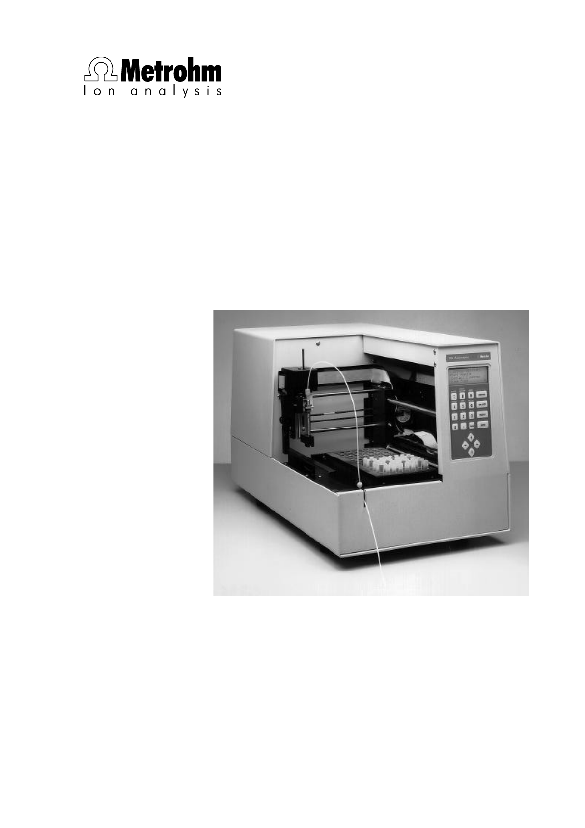
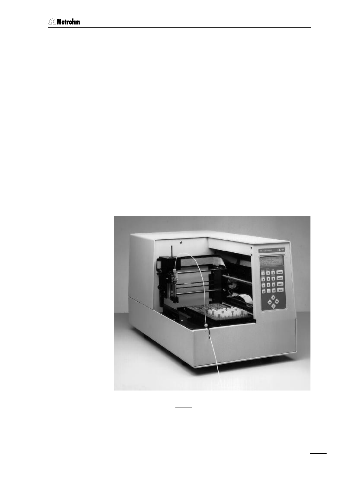
Fig. 1: Autosampler 750 ............................................................................................... 1
Fig. 2: Positive displacement sample injection ............................................................2
Fig. 3: Displacement volume versus needle position .................................................. 3
Fig. 4: Front of 750 Autosampler.................................................................................. 4
Fig. 5: Rear of 750 Autosampler................................................................................... 5
Fig. 6: Connection of 750 Autosampler to 732/733 ................................................... 11
Fig. 7: Connection of 750 Autosampler to 732/733 and 762 ..................................... 13
Fig. 8: Keypad ............................................................................................................ 20
Abb. 9: Manual sample filtering ................................................................................... 39
Fig. 10: Sample filtering with FilterCaps....................................................................... 40
Fig. 11: Transfer needle replacement........................................................................... 51
Fig. 12: Valve control .................................................................................................... 57
Fig. 13: Inputs/outputs.................................................................................................. 51
II
750 Autosampler
Page 4
1 Introduction
1.1 Instrument description
The 750 Autosampler is a microcomputer-operated sampling/controller system designed to be used with the ion chromatographic instruments 732 IC Detector and 733 IC Separation Center. It has a capacity of up to 128 samples, which are transferred automatically into
the sample loop of the 733 IC Separation Center.
The 750 Autosampler performs up to four, fixed loop injections per vial
at user-selectable time intervals. All operating parameters are entered
from the front panel. Additionally, the instrument can be controlled remotely either by an externally programmable contact closure or through
the RS232 connector located on the rear panel.
1.1 Instrument description
750 Autosampler
Fig. 1: 750 Autosampler
1
Page 5
1 Introduction
Sample
Needle
Cap
Sample vial
Valve
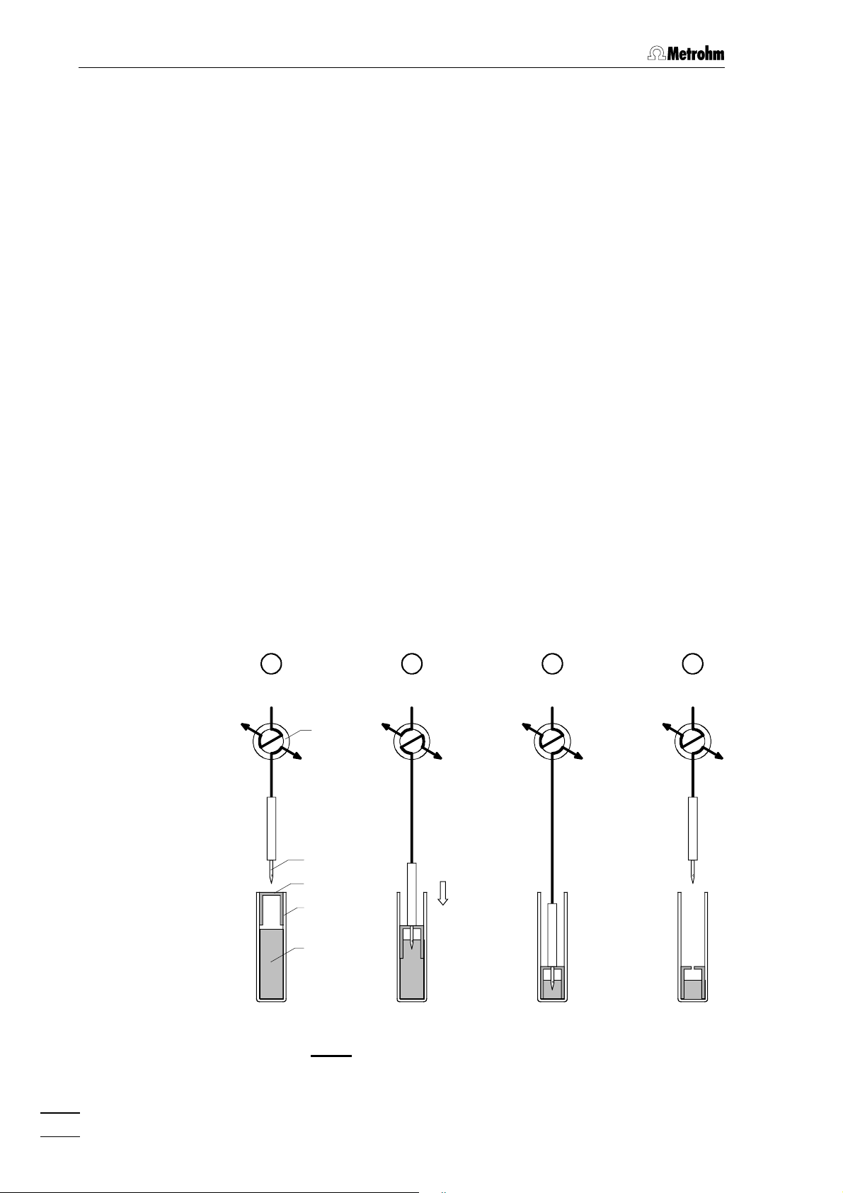
1.2 Theory of operation
Displacement principle
The 750 Autosampler operates using the positive displacement principle of sample transfer. This sample transfer process into the sample
loop of the 733 IC Separation Center is illustrated in Fig. 2. When an injection is initiated, the hollow transfer needle 55 descends into the vial.
The needle tip punctures the polyethylene cap of the sample vial. The
opening into the needle is located on the side to minimize plugging by
cap material as the cap is punctured. The needle continues downward
until the pushrod contacts the area around the puncture in the cap
which forces the cap down into the vial. The piston action of the cap
pressurizes the sample and forces it up through the needle and the
transfer tubing 88 that is connected to the needle. From the transfer
tubing, the sample flows through the injection valve and sample loop
with the excess passing on through the waste tube to a waste container.
Column
Rinsing by air bubbles
The air bubble (minimum 150 µL), which is always present at the top of
a properly filled and capped vial, precedes the sample stream through
the plumbing. The bubble disrupts the laminar flow of the fluid in the
tubing while pushing out the previous sample and solvent. This effect,
in addition to the large excess volume of sample, helps to minimize
sample carryover.
A B C D
Eluent
Waste
RUN FILL/LOAD
INJECT
RUN
Fig. 2: Positive displacement sample injection
2
750 Autosampler
Page 6
1.2 Theory of operation
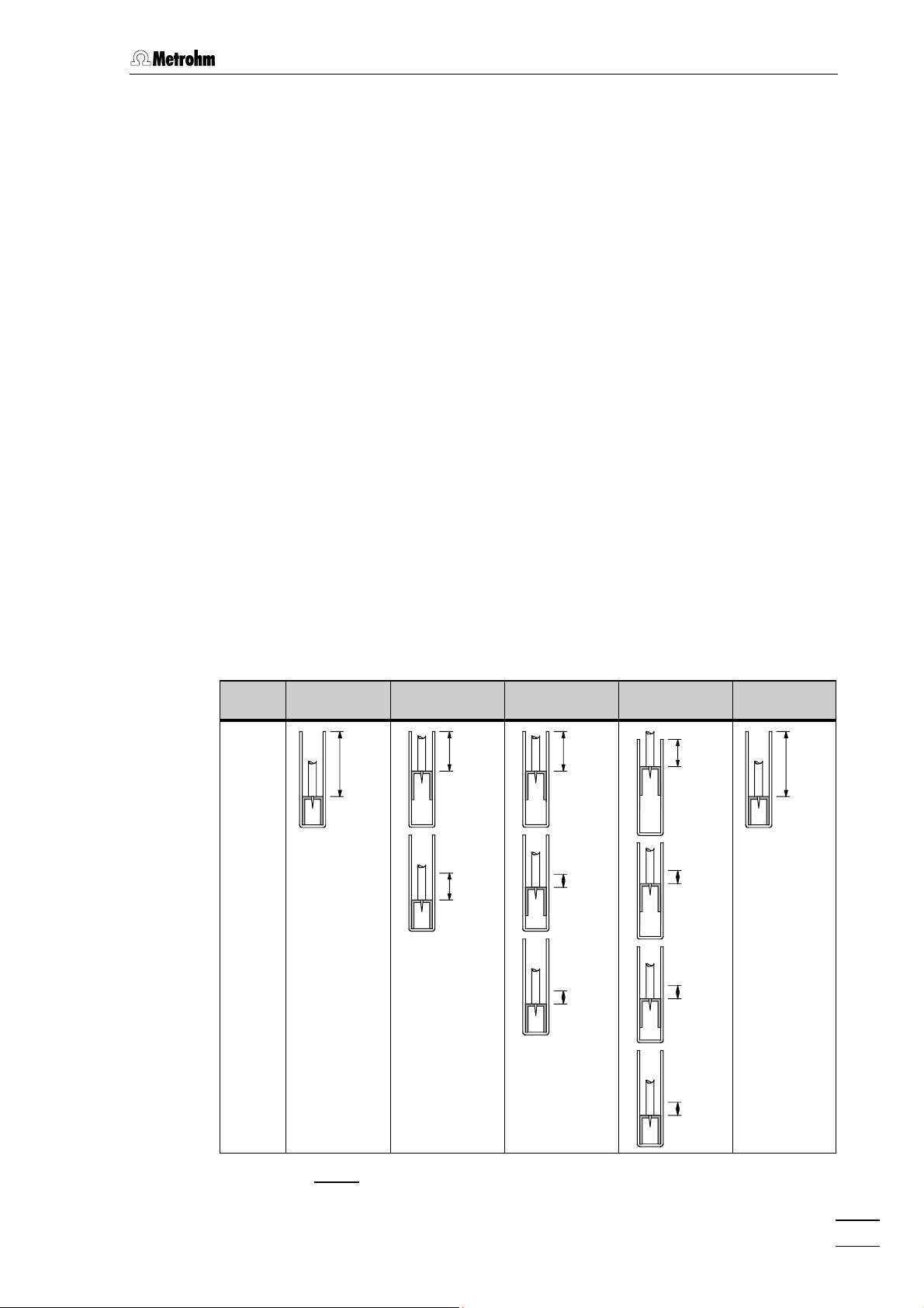
Number of injections
The number of injections per sample with the 750 Autosampler depends on the sample loop size. With sample loops > 10 µL max. 3,
with sample loops ≤ 10 µL max. 4 injections are possible. Fig. 3 details
the needle position and displacement volume at the sample delivery
action. Care should always be taken that the injection volume is at least
three times greater than the volume of the sample loop. This is why only
a maximum of 2 injections per sample should be made with 100 µL
loops; the minimum sample volume is 300 µL for 1 and 600 µL for 2 injections. For sample loops with a volume ≤ 10 µL up to 4 injections per
sample are possible. The minimum sample volume required is 150 µL
for 1, 300 µL for 2, 450 µL for 3 and 600 µL for 4 injections.
Rinsing
Rinsing will be necessary for highly concentrated samples or for samples that may absorb in the tubing or in the injection valve. Rinse vials
are filled with eluent or other suitable solvent. The Rinse process is
shown in Fig. 3. Rinse vials can be used either after each vial (every
even numbered or odd numbered vial) or at programmed vial intervals.
There are two types of Rinses, the Normal Rinse and the Quick Rinse.
The Normal Rinse occurs after all the injections have been made from
the sample vial and the run time has elapsed. A Quick Rinse occurs
immediately after an injection and is used in applications where the
sample solution must not be left in the needle, transfer tubing or valve
for whatever reason. Only one injection per vial can be programmed
when using a Quick Rinse.
Injection
1
2
3
4
1 Injection
per vial
2.65 cm
730
µL
2 Injections
per vial
1.63 cm
450
µL
1.02 cm
280
µL
3 Injections
per vial
1.63 cm
450
µL
0.51 cm
140
µL
0.51 cm
140
µL
4 Injections
per vial Rinse
1.12 cm
310
µL
0.51 cm
140
µL
0.51 cm
140
µL
0.51 cm
140
µL
2.65 cm
730
µL
750 Autosampler
Fig. 3: Displacement volume versus needle position
3
Page 7
1 Introduction
1.3 Control elements
750 Autosampler
MANUAL
METHOD
8 9
7
5 6
4
1
2 3
0
.
11
RINSEINJECTION
FUNCTION
REM/LOCTEMPSYSTEM
RUN/STOP
F3F2F1
PRIORITY
CLEAR
ENTER
22
88
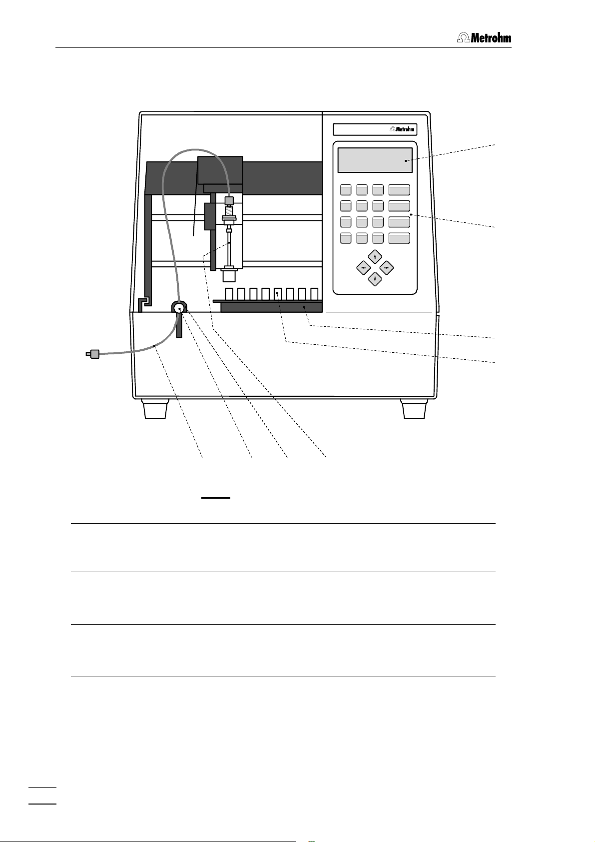
Fig. 4: Front of the 750 Autosampler
11 Display (LCD)
comprising 4 lines each of
20 characters
22 Keypad
with function, numeric and cursor
keys (details see chap. 3.1.2)
33
44
556677
55 Transfer needle
66 Holder for transfer tubing
33 Sample rack (6.2041.600)
77 Holder stopper
for 128 sample vials
44 Sample vial
6.2743.000 sample vial (PP) or
6.2413.000 sample vial (glass)
88 Transfer tubing
6.1803.000 PTFE capillary for the
connection of the 750 Autosampler
with the injector of the 733 IC
Separation Center
4
750 Autosampler
Page 8
1.3 Control elements
1010
99
BCD
INJECT
LOAD
IEEE
EXT PWR
CONTROL
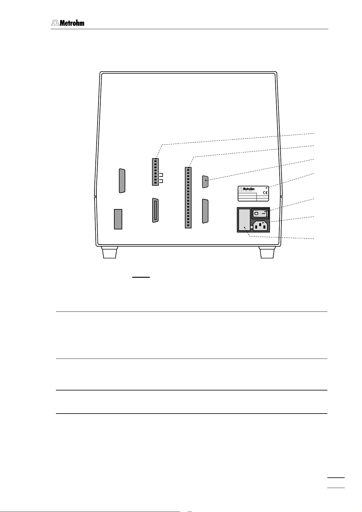
Fig. 5: Rear of the 750 Autosampler
99 Contact closure strip for valve
control
details see chap. 5.2.1
RS-232
PRINTER
Type:
Nr.:
U:
1313 Mains switch
switch to switch the instrument on
and off:
OFF
Switzerland
Hz
f:
VA
V
S:
I = ON 0 =
1111
1212
1313
1414
1515
1010 Contact closure strip for external
control
details see chap. 5.2.1
1111 RS232 interface
details see chap. 5.2.2
1212 Model plate
with instrument and serial number,
mains voltage, mains frequency,
power consumption
750 Autosampler
1414 Mains connection plug
mains connection see chap. 2.3
1515 Fuse cassette
changing the fuses, see chap. 2.3.1
5
Page 9

1 Introduction
1.4 Information on the Instructions for Use
Please read through these Instructions for Use carefully before you put
the 750 Autosampler into operation. The Instructions for Use contain
information and warnings which must be heeded by the user to assure
safe operation of the instrument.
1.4.1 Organization
These 8.750.1023 Instructions for Use for the 750 Autosampler provide a comprehensive overview of the installation, startup procedure,
operation, fault rectification and technical specifications of the instrument. The Instructions for Use are organized as follows:
Section 1 Introduction
General description of instruments, control parts
and safety notes
Section 2 Installation
Installation of the 750 Autosampler, connection to
IC Separation Center 733, initial checkout
Section 3 Operation
Detailed description of the operation and
explanation of functions of all keys
Section 4 Notes – Maintenance – Faults
Notes on operation, maintenance,
fault rectification, diagnostic tests
Section 5 Appendix
Technical data, interfaces, standard equipment,
options, warranty, declarations of conformity, index
To find the required information on the instruments, you will find it an
advantage to use either the Table of contents or the Index at the
back.
6
750 Autosampler
Page 10
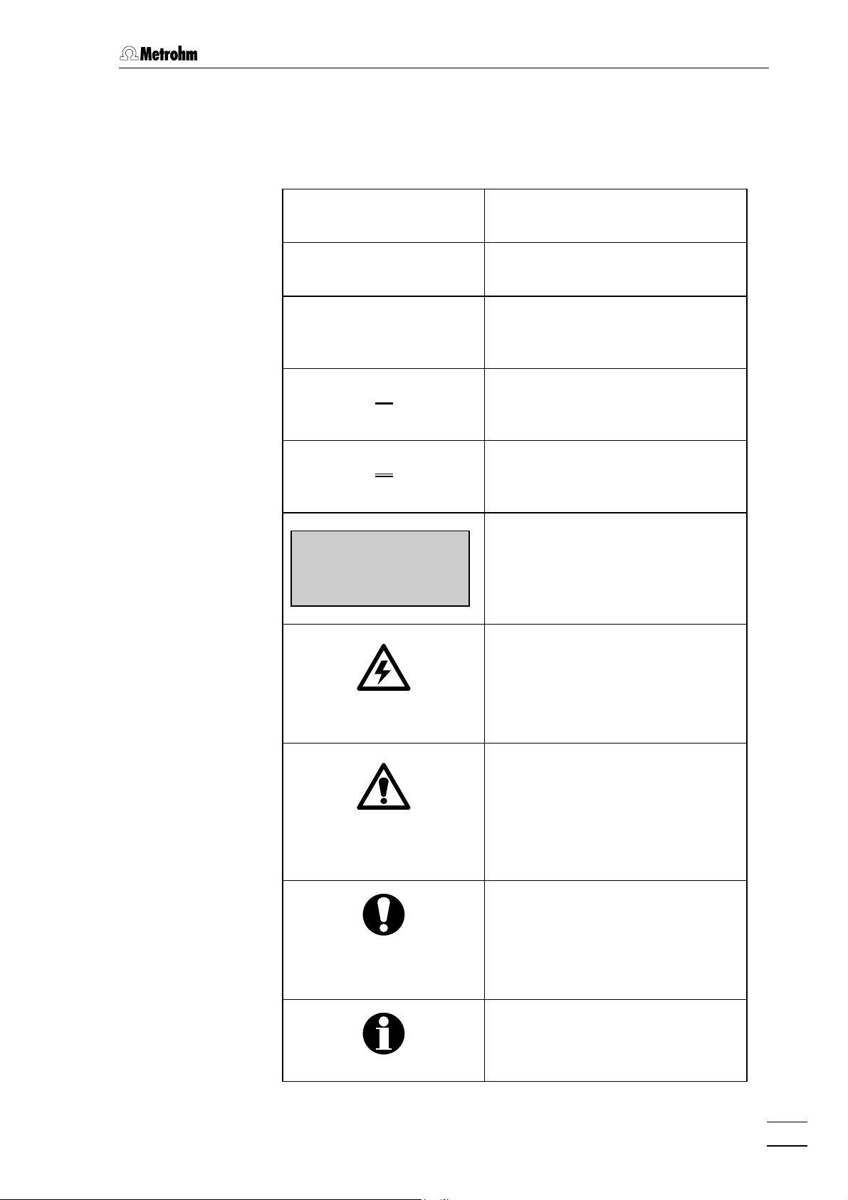
1.4.2 Notation and pictograms
The following notations and pictograms (symbols) are used in these Instructions for Use:
<PARAM> Key
"Run Time" Parameter or entry value
55 Control element of 750
8484 Control element of 732/733
1.4 Information on the Instructions for Use
(see chap. 1.3)
(see Instructions for Use 732)
1414 Control element of 762
READY
SELECT A FUNCTION
(see Instructions for Use 762)
Display
Text in display 11 of the 750 Auto-
sampler
Hazard
This symbol draws attention to a
possible danger to life or of injury if
the associated directions are not
followed correctly.
Warning
This symbol draws attention to
possible damage to instruments or
instrument parts if the associated
directions are not followed correctly.
750 Autosampler
Caution
This symbol marks important information. First read the associated directions before you continue.
Comment
This symbol marks additional information and tips.
7
Page 11
1 Introduction
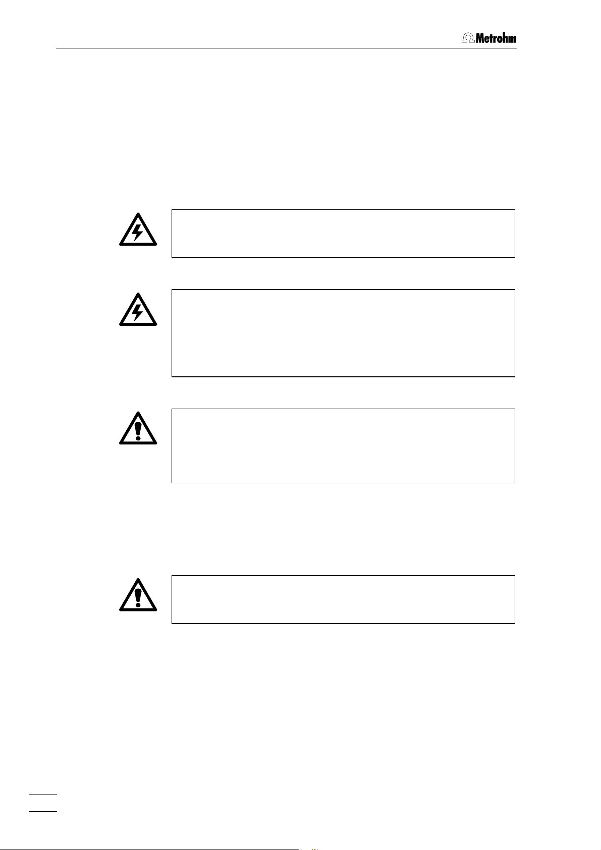
1.5 Safety notes
1.5.1 Electrical safety
While electrical safety in the handling of the 750 Autosampler is assured
in the context of the specifications IEC 1010-1 (protection class 1, degree of protection IP20), the following points should be noted:
• Mains connection
Setting the mains voltage, checking the mains fuse and the mains
connection must be effected in accordance with the instructions in
section 2.3.
• Opening the 750 Autosampler
When the 750 Autosampler is connected to the power supply the
instrument must neither be opened nor should parts be removed from
it, otherwise there is a danger of coming into contact with components which are live. Always disconnect the instrument from all voltage
sources before you open it and ensure that the mains cable is
disconnected from mains connection plug 1414 !
• Protection against static charges
Electronic components are sensitive to static charging and can be
destroyed by discharges. Before you touch any of the components
inside the 750 Autosampler, you should earth yourself and any tools
you are using by touching an earthed object (e.g. housing of the
instrument or a radiator) to eliminate any static charges which exist.
1.5.2 General precautionary rules
• Handling of solvents
Check all tubing of the IC system periodically for possible leaks.
Follow the relevant instructions regarding the handling of flammable
and/or toxic solvents and their disposal.
8
750 Autosampler
Page 12

2 Installation
2.1 Setting up the instrument
2.1.1 Packaging
The 750 Autosampler is supplied together with the separately packed
accessories in special packagings containing shock-absorbing foam
linings designed to provide excellent protection. The actual instrument
is packed in an evacuated polyethylene bag to prevent the ingress of
dust. Please store all these special packagings as only they can assure
damage-free transport of the instrument.
2.1.2 Check
2.1 Setting up the instrument
2.1.3 Location
After receipt, immediately check whether the shipment is complete and
has arrived without damage (compare with delivery note and list of
accessories in section 5.3). In the case of transport damage, see
instructions in section 5.5.1 "Warranty".
Position the instrument in the laboratory at a location convenient for operation, free from vibrations and protected against a corrosive atmosphere and contamination by chemicals. The Autosampler should be located as close as possible to the IC system to minimize dead volume.
When not in use the instrument should always be covered with the
6.2742.010 dust cover.
750 Autosampler
9
Page 13
2 Installation
2.2 Connection to IC system
2.2.1 750 Autosampler as "Master"
When an IC system consisting of 732 IC Detector, 733 IC Separation
Center, and 709 IC Pump is operated with the 750 Autosampler as
"Master" the command to start the next injection after the analysis time
"Run Time" has elapsed will be given by the Autosampler itself. In this
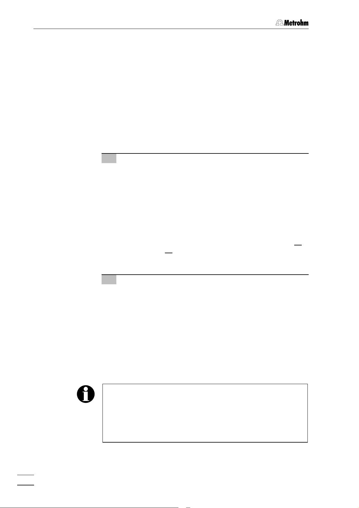
case the 750 Autosampler is connected to the 733 IC Separation Center with the 6.2128.100 cable as shown in Fig. 6. In addition the 709 IC
Pump can be connected to the 750 Autosampler in such a way that
when the pump stops the Autosampler will also be automatically
stopped (important for unattended continuous operation).
Electrical connection 750 – 733
1
• Connect 6.2140.020 connector plug to contact closure strip 99
of the 750 Autosampler.
• Connect one end of the 6.2128.100 cable to the connections
"LOAD NO", "LOAD COM", "INJECT NO" and "INJECT COM"
on the connector plug inserted in the contact closure strip 99.
The four cable ends are appropriately inscribed with "LOAD
NO" (green), "LOAD COM" (yellow), "INJECT NO" (brown) and
"INJECT COM" (white).
• Connect the other end of the 6.2128.100 cable to the con-
nections "Ground", "Fill" and "Inject" on the terminal block 3838
(valve A) or 4646 (valve B) of the 733 IC Separation Center. The
three cable ends are appropriately inscribed with "GND"
(white), "FILL" (green) and "INJECT" (brown).
Electrical connection 750 – 709 (optional)
2
• Connect 6.2140.010 connector plug to contact closure strip
1010 of the 750 Autosampler.
• Connect jumper P12 to the control interface of the 709 IC
Pump in such a way that the contacts at outputs 3 and 4 will
be closed when the pump has stopped (see chap. 5.2 of the
709 Instructions for Use).
• Use 6.2134.070 cable (option) to connect outputs 3 and 4 of
the control interface on the 709 IC Pump with connection
"REMOTE STOP INPUT" and "GND" on contact closure strip
1010 of the 750 Autosampler.
Settings with 750 Autosampler as "Master"
The following settings are recommended for operating the IC system
with 750 Autosampler as "Master":
• 750 Autosampler: "Run Time" ≥ 3.0 min
• 732 IC Detector: operation without program or
with "Inject" program
10
750 Autosampler
Page 14
2.2 Connection to IC system
Cable 732/Evaluation
System (analog signal)
Evaluation system
Cable 732/Evaluation
system (start signal)
732
733
6.2115.070
709
6.2125.090
6.2125.060
6.2134.070
750
6.2128.100
INJECT
LOAD
Fig. 6: Connection of 750 Autosampler at 732/733
2.2.2 732 IC Detector as "Master"
When an IC system consisting of 732 IC Detector, 733 IC Separation
Center, and 709 IC Pump is operated with the 732 IC Detector as
"Master" the 750 Autosampler sample change procedure will be started
by a signal from the 733 IC Separation Center. The Autosampler must
be connected to the 733 IC Separation Center with two cables as
shown in Fig. 6. In addition the 709 IC Pump can be connected to the
750 Autosampler in such a way that when the pump stops the Autosampler will also be automatically stopped (important for unattended
continuous operation).
Electrical connection 750 – 733
1
• Connect 6.2140.020 connector plug to contact closure strip 99
and 6.2140.010 connector plug to contact closure strip 1010of
the 750 Autosampler.
• Connect one end of the 6.2128.100 cable to the connections
"LOAD NO", "LOAD COM", "INJECT NO" and "INJECT COM"
on the connector plug inserted in the contact closure strip 99.
The four cable ends are appropriately inscribed with "LOAD
NO" (green), "LOAD COM" (yellow), "INJECT NO" (brown) and
"INJECT COM" (white).
• Connect the other end of the 6.2128.100 cable to the con-
nections "Ground", "Fill" and "Inject" on the terminal block 3838
(valve A) or 4646 (valve B) of the 733 IC Separation Center. The
three cable ends are appropriately inscribed with "GND"
(white), "FILL" (green) and "INJECT" (brown).
750 Autosampler
11
Page 15
2 Installation
• Connect one end of the 6.2115.070 cable (option) to the
connections "EXTERNAL INJECT INPUT" and "GND" on the
connector plug inserted in the contact closure strip 1010.
• Connect the other end of the 6.2115.070 cable to the con-
nections "Pos. Fill" on the terminal block 3838 (valve A) or 4646
(valve B) of the 733 IC Separation Center so that COM and
GND are connected.
Electrical connection 750 – 709 (optional)
2
• Connect jumper P12 to the control interface of the 709 IC
Pump in such a way that the contacts at outputs 3 and 4 will
be closed when the pump has stopped (see chap. 5.2 of the
709 Instructions for Use).
• Use 6.2134.070 cable (option) to connect outputs 3 and 4 of
the control interface on the 709 IC Pump with connection
"REMOTE STOP INPUT" and "GND" on contact closure strip
1010 of the 750 Autosampler.
Settings with 732 IC Detector as "Master"
The following settings are recommended for operating the IC system
with 732 IC Detector as "Master":
• 750 Autosampler: "Run Time" = 0.0 min
• 732 IC Detector: operation with cycle program with
command "valve A/B = fill" at time
"0.0 min".
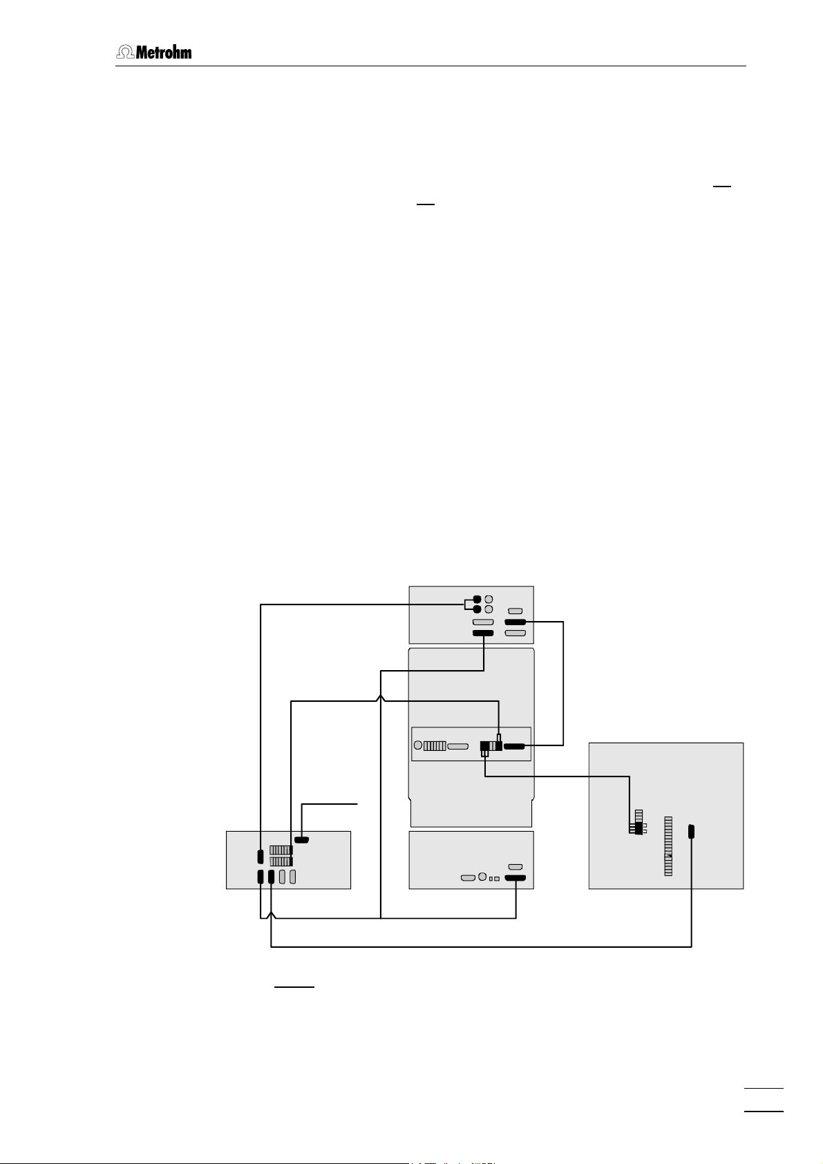
2.2.3 Connection to 762 with «IC Net»
When a modular IC system consisting of 732 IC Detector, 733 IC
Separation Center, 709 IC Pump, and 762 IC Interface is operated with
the PC software «IC Net» as "Master" the 750 Autosampler sample
change procedure will be started by a signal from the 733 IC Separation Center. The Autosampler must be connected to the 762 IC Interface using the 6.2134.000 cable and to the 733 IC Separation Center
using the 6.2128.100 as shown in Fig. 7.
Electrical connection 750 – 762
1
• Connect RS232 interface 1111 at the 750 Autosampler to one of
the RS232 interfaces 1414 or 1818 at the 762 IC Interface using
the 6.2134.000 cable.
12
Electrical connection 750 – 733
2
• Connect 6.2140.020 connector plug to contact closure strip 99
of the 750 Autosampler.
• Connect one end of the 6.2128.100 cable to the connections
"LOAD NO", "LOAD COM", "INJECT NO" and "INJECT COM"
on the connector plug inserted in the contact closure strip 99.
750 Autosampler
Page 16
2.2 Connection to IC system
The four cable ends are appropriately inscribed with "LOAD
NO" (green), "LOAD COM" (yellow), "INJECT NO" (brown) and
"INJECT COM" (white).
• Connect the other end of the 6.2128.100 cable to the con-
nections "Ground", "Fill" and "Inject" on the terminal block 3838
(valve A) or 4646 (valve B) of the 733 IC Separation Center. The
three cable ends are appropriately inscribed with "GND"
(white), "FILL" (green) and "INJECT" (brown).
732
6.2128.130
733
6.2125.090
(732)
6.2115.070
750
6.2128.100
6.2134.100
PC
6.2134.090
709762
6.2134.000
INJECT
LOAD
Fig. 7: Connection of 750 Autosampler at 732/733 and 762
750 Autosampler
13
Page 17

2 Installation
2.2.4 Tubing connection
For transferring the sample from the 750 Autosampler to the injection
valve of the 733 IC Separation Center the following tubing connections
must be made:
Tubing connection 750 – injection valve
1
• At the 733 IC Separation Center, loosen the rotary nipple
screwed onto the interior side of connection 2222 or 2828.
• Take PTFE suction tubing 8888 (see Fig. 16 and Fig. 17 of the
732/733 Instructions for Use) completely out of connection 2222
or 2828 and unscrew from connection "1" of injection valve 6868.
• Cut transfer tubing 88 (6.1803.000 PTFE capillary tubing of 750
accessories) to the shortest possible length between the
needle of the 750 Autosampler and injection valve 6868 of the
733 IC Separation Center.
• Remove the cover from transfer needle 55 of the 750 Auto-
sampler and screw one end of transfer tubing 88 to this con-
nection with the aid of a 6.2744.010 PEEK compression fitting.
• Remove holder stopper 77 from holder 66 and pull 6.1803.000
PTFE capillary tubing so far through the opening of holder
stopper 77 that the tubing length between needle connection
and the holder stopper is about 30 cm. Then press holder
stopper 77 fully back into holder 66.
• Pull the other end of the transfer tubing 88 through the opening
2222 or 2828 of the 733 IC Separation Center and screw onto
connection "1" of injection valve 6868 using a 6.2744.010 PEEK
compression fitting.
• Retighten rotary nipple on the interior side of connection 2222
or 2828 to fix the capillary tubing.
14
Tubing connection injection valve – waste
2
• Insert 6.2744.020 coupling (from 733 accessories) into con-
nection 2121 or 2727 of the 733 IC Separation Center.
• Screw PTFE suction tubing 8888 onto the 6.2744.020 coupling
attached to connection 2121 or 2727 and lead it into the waste
container.
In the case of the 2.733.0X20 IC Separation Center with two injection
valves, it is possible to fill both sample loops from the same 750
Autosampler. For this, connection "1" of valve A (outlet of the sample
loop) must be connected to connection "2" of valve B (inlet of the
sample loop) using a 6.1803.000 PTFE Capillary tubing cut to the
appropriate length.
750 Autosampler
Page 18
2.3 Mains connection
Follow the instructions below for connecting to the power supply. If
the instrument is operated with the mains voltage set wrongly and/or
wrong mains fuse there is a danger of fire!
2.3.1 Check fuses
The selection of mains voltage (100, 120, 220 or 240 V) and mains frequency (50 or 60 Hz) is made automatically by the 750 Autosampler
according to the mains voltage and frequency used. Nevertheless, before the 750 Autosampler is switched on for the first time a check
should be made as to whether the correct fuses for the intended mains
supply have been inserted in the instrument. Proceed as follows:
Disconnect mains cable
1
Disconnect mains cable from mains connection plug 1414 of the
750 Autosampler (see Fig. 5).
2.3 Mains connection
Remove fuse cassette
2
Using a screwdriver, loosen fuse cassette 1515 alongside the
mains connection plug 1414 and take out completely.
Remove fuse holder
3
Lift up the spring clip on the upper side of fuse cassette 1515 and
remove the fuse holder completely from the fuse cassette.
Check fuses
4
Carefully take the two fuses out of the fuse holder and check
their specifications:
100……120 V 2 A (rapid-action, with low rup-
turing capacity, 3AG)
230……240 V 1.25 A (rapid-action, with low rup-
turing capacity, 5××20 mm)
Insert fuses
5
Change fuses if necessary and reinsert in fuse holder.
Install fuse holder
6
Push the fuse holder into fuse cassette 1515 until the spring clip
clicks into position.
750 Autosampler
Insert fuse cassette
7
Completely reinsert fuse cassette 1515 in 750 Autosampler.
15
Page 19
2 Installation
2.3.2 Mains cable and mains connection
Mains cable
The instrument is supplied with one of three mains cables
• 6.2122.020 with plug SEV 12 (Switzerland, …)
• 6.2122.040 with plug CEE(7), VII (Germany, …)
• 6.2133.070 with plug NEMA 5-15 (USA, …)
which are three-cored and fitted with a plug with an earthing pin. If a
different plug has to be fitted, the yellow/green lead (IEC standard)
must be connected to protective earth (protection class 1).
Any break in the earthing inside or outside the instrument can make it
a hazard!
Mains connection
Plug the mains cable into mains connection plug 1414 of the 750 Auto-
sampler (see Fig. 5).
2.3.3 Switching the instrument on/off
The 750 Autosampler is switched on and off using mains switch 1313.
When the instrument is switched on display 11 lights up.
16
750 Autosampler
Page 20
2.4 Initial checkout
Initial checkout will prove the general operation of the instrument and
show that no shipping damage or installation problem exists which
would prevent normal operation. To carry out this checkout the 750
Autosampler must be connected to the 733 IC Separation Center as
described in chap. 2.2 and correctly connected to the mains supply as
described in chap. 2.3.
For the initial checkout a standard chromatogram for the separation
column used in the 733 IC Separation Center should be recorded. In
order to do this a sample vial 44 filled with at least 500 µL of a suitable
standard ion solution should be placed in position 1 of sample rack 33;
then proceed step by step as follows:
Switch on 750 Autosampler
1
Switch on 750 Autosampler with mains switch 1313. The following
screen will be displayed after powerup and initialization:
2.4 Initial checkout
READY
SELECT A FUNCTION
Select "MANUAL INJECTION"
2
Press the <MANUAL INJECTION> key (<FUNCTION> +
<8>). The following screen will appear:
MANUAL INJECTION
àà
Sample Vial 1
Needle Depth POS 1
Run Injection ââ
Enter sample vial position
3
Press the <1> key and then press the <ENTER> key. The
screen will now change to:
MANUAL INJECTION
Sample Vial 1
àà
Needle Depth POS 1
Run Injection ââ
750 Autosampler
Enter needle depth
4
Press the <→> key two times and then press the <ENTER>
key. This results in the following display:
MANUAL INJECTION
Sample Vial 1
Needle Depth POS 3
àà
Run Injection ââ
17
Page 21

2 Installation
Start injection
5
Press the <ENTER> key. The 750 Autosampler will make an
injection from the vial at position 1. Afterwards the following
display will appear:
MANUAL INJECTION
COMPLETED
Select "SYSTEM"
6
Press the <SYSTEM> key (<FUNCTION> + <4>). The following screen will appear:
SYSTEM SETTINGS
àà
Park Needle
Contact Closures
Loop Size ââ
Park needle
7
Press the <ENTER> key. The transfer needle will be withdrawn
from the sample vial and moved back to its parking position in
the back left-hand corner. The following display then reappears:
READY
SELECT A FUNCTION
If any difficulties should occur during the initial checkout then proceed
as described in chap. 4.3.
18
750 Autosampler
Page 22

3 Operation
3.1 Fundamentals of operation
3.1.1 Display and instrument dialog
The LCD display 11 on the 750 Autosampler consists of 4 lines each with
20 characters. After the Autosampler has been switched on and initialized the following display appears:
READY
SELECT A FUNCTION
This screen is called the main screen. It is always displayed any time
the instrument is idle. Note that the line "SELECT A FUNCTION" flashes.
3.1 Fundamentals of operation
Methods, system settings, and other functions consist of a menu of
parameters which can be edited for different sample requirements. The
complete parameter menu, in many instances, cannot be shown on the
display at one time due to the available number of display lines. For example, a typical menu has the following appearance:
MANUAL INJECTION
Sample Vial 1
àà
Needle Depth<POS 3>
Run Injection ââ
The first line always shows the title of the selected function. Parameters
which can be edited with the numerical and/or cursor keys are shown
beneath. If the arrows "áá" or "ââ" appear at the right-hand side this indi-
cates that the cursor keys <áá> and <ââ> can be used to scroll
through the menu. In most menus the last entry is "Exit" (return to basic
condition).
An arrow pointing to the right "àà" on the left-hand side shows the pa-
rameter which can currently be edited. Each parameter requires either
a numerical entry or the selection of a value from an existing list.
Numerical parameter values are entered either directly with the numerical keys, or the <àà> and <ßß> keys are used to increase or decrease
the value step by step. The <CLEAR> key is used to delete an incorrect entry. When the required value for the parameter is shown it must
be confirmed. This is done with the <ENTER> key or by changing to
the next or previous parameter with the <áá> or <ââ> keys.
If a numerical entry is made which is outside the range possible for that
parameter the Autosampler will issue a warning alarm, followed by the
display of the following error message:
750 Autosampler
19
Page 23

3 Operation
Numeric keys
ERROR
Value out of range
Enter value between
## - ####
where # and ## are the appropriate range limits. The error message will
remain on the display until the <CLEAR> key is pressed.
Parameter lines which contain the characters "<" and/or ">" (e.g. "NONE>")
on either side of the parameter value indicate that a selection must be
made from a discreet menu of items. Pressing either the <àà> or <ßß>
key allows scrolling through the selection list. When the desired selection is displayed, press either the <ENTER>, <áá> or <ââ> key to
confirm the selection.
3.1.2 Overview of key functions
METHOD
MANUAL
RINSEINJECTION
8 9
7
4
1
0
REM/LOCTEMPSYSTEM
5 6
2 3
.
F3F2F1
CLEAR
Fig. 8: Keypad
FUNCTION
RUN/STOP
Main function keys
PRIORITY
ENTER
Cursor keys
20
The keypad of the 750 Autosampler contains 4 main function keys, 12
numerical keys (incl. <CLEAR>) and 4 cursor keys. In the basic condition the functions given above the numbers can also be activated by
pressing the <FUNCTION> key and the corresponding numeric key.
The following table provides a brief overview of the different functions of
the individual keys of the 750 Autosampler. You will find more detailed
information on the key functions in sections 3.2…3.8.
750 Autosampler
Page 24

Keys of 750 Autosampler
Key Normal function Function with <FUNCTION>
3.1 Fundamentals of operation
FUNCTION
RUN/STOP
PRIORITY
ENTER
METHOD
7
Function key
• Selection of a function in combi-
nation with the corresponding
numeric key.
Run/Stop key
• If no method runs:
Selection and start of a method.
• If a method runs:
Stop of the running method.
Key for priority sample
• Interruption of a running method
and injection of a priority sample.
Enter key
• Confirmation of entered parame-
ter.
Numeric entry 7
• Numeric entry of number "7".
–
–
–
–
Method
• Selection of method menu for
editing or deleting methods.
MANUAL
INJECTION
8
RINSE
9
SYSTEM
4
TEMP
5
REM/LOC
6
Numeric entry 8
• Numeric entry of number "8".
Numeric entry 9
• Numeric entry of number "9".
Numeric entry 4
• Numeric entry of number "4".
Numeric entry 5
• Numeric entry of number "5".
Numeric entry 6
• Numeric entry of number "6".
Manual injection
• Selection of the "MANUAL
INJECTION" menu for injections to be made from a
specified sample vial.
Rinse
• Rinsing of the transfer needle
and the injection valve with a
rinsing solution.
System parameters
• Selection of the menu for
system settings.
No function
• The <TEMP> function is not
available.
Remote control
• Selection of the menu for the
remote control (Local/RS232).
750 Autosampler
21
Page 25

3 Operation
Key Normal function Function with <FUNCTION>
F1
1
F2
2
F3
3
0
.
CLEAR
Numeric entry 1
• Numeric entry of number "1".
Numeric entry 2
• Numeric entry of number "2".
Numeric entry 3
• Numeric entry of number "3".
Numeric entry 0
• Numeric entry of number "0".
Point
• Entry of decimal point ".".
Delete/reset
• Deletion of an entered parameter
and/or resetting to default value.
No function
• The <F1> function is not
available.
No function
• The <F2> function is not
available.
No function
• The <F3> function is not
available.
Shipping position
• Transfer needle is moved to
the shipping position.
–
"Escape"
• Exit from parameter menus
and return to standby mode.
Cursor key <á>
• Moves the display cursor up a
line.
Cursor key <â>
• Moves the display cursor down a
line.
Cursor key <ß>
• Decrements numerical parameter
values.
• Moves the display one selection
item to the left.
Cursor key <à>
• Increments numerical parameter
values.
• Moves the display one selection
item to the right.
"Escape"
• Exit from parameter menus
and return to standby mode.
–
–
–
22
750 Autosampler
Page 26

3.2 System settings
3.2 System settings
SYSTEM
By pressing the <SYSTEM> key (<FUNCTION> + <4>) the system
settings menu appears. The system settings are global parameters
which affect the operation of the Autosampler, but are not required to
4
be programmed for each sample or method. The following screen
results:
SYSTEM SETTINGS
Park Needle
Contact Closures
Loop Size
Needle Setup
Key Beep
Time/Date
Injection Valve
Exit
Status
The individual menu points are selected by pressing the <áá> and
<ââ> keys. The individual inquiries of a menu point are accessed using
the <ENTER> key and exited by pressing simultaneously the
<FUNCTION> + <CLEAR> keys. The following listings show all dialog items which appear under <SYSTEM>. The values shown in the
displays are the default values, the possible entry values or ranges are
shown below the display.
System settings
Park transfer needle in home position
Enter contact closure times
Specify injection loop
Specify needle settings
On/off switching of the audible beep
Set date/time
without function for 750 Autosampler
Return to standby mode
Status display
SYSTEM SETTINGS
à
Park Needle
SYSTEM SETTINGS
à
Contact Closures
Park transfer needle in home position
After confirmation of this command with <ENTER> the transfer
needle is moved to the left rear of the instrument to provide easy
access to the sample rack.
Contact closure times
On the 750 Autosampler there is the possibility of producing four
signals in the form of a contact closure on contact closure strip 1010
for controlling external instruments:
Injection Automatic contact closure at output "START" for every
injection triggered by the Autosampler.
Event 1 Contact closure after a time laid down in the method
at output "T1".
Event 2 Contact closure after a time laid down in the method
at output "T2".
Event 3 Contact closure after a time laid down in the method
at output "T3".
Both signals are produced not only as "normal open" (between
outputs NO – COM) but also as "normal closed" (between outputs
NC – COM).
Entry of <ENTER> opens the following menu:
750 Autosampler
23
Page 27

3 Operation
CLOSURE DURATIONS
à
Injection 1
1…32000 s
CLOSURE DURATIONS
à
Event # 1
1…32000 s
CLOSURE DURATIONS
à
Exit
SYSTEM SETTINGS
à
Loop Size
Contact closure time for "START"
Input of contact closure time for the signal to be produced at
output "START" when the injection valve is switched to the
"INJECT" position.
Contact closure time for "T1", "T2" or "T3"
Entry of contact closure time for the signal to be produced at
output "T#". The signal output is made according to the time
laid down in the method "Event# Time".
Return to "SYSTEM SETTINGS" menu
Loop size
Size of the loop at the injection valve at the 733 IC Separation
Center. By pressing <ENTER> the following screen is displayed:
Enter Loop Size
10µµL
(Four injs/vial)
SYSTEM SETTINGS
à
Needle Setup
NEEDLE SETUP
à
Depth
Enter Needle
position for ONE
injection per vial.
<POS 3>
POS1,POS2,POS3,POS4
1…100 µL
Entry of loop size
Entry of loop size in µL. In the bottom line the number of
possible injections per sample is displayed. For a volume of
≤ 10 µL the maximum is 4, for a volume > 10 µL a maximum
of 3 injections can be made.
Needle settings
By pressing <ENTER> the following menu is opened:
Depth Needle depth.
Pressure Pressure for needle lowering.
Needle depth
By pressing <ENTER> the following screen is displayed:
Entry of needle depth
Entry of the position to which the transfer needle is lowered
with 1 injection per sample. The positions correspond to the
following displacement volumes (see section 1.2):
POS1 310 µL POS3 590 µL
POS2 450 µL POS4 730 µL
24
If sample vessels closed with 6.2743.030 filter stoppers are used then
immersion depth "POS4" must not be selected.
750 Autosampler
Page 28
3.2 System settings
NEEDLE SETUP
à
Pressure Low>
SYSTEM SETTINGS
à
Key beep
Audible Key Feedback
Selection
<ON
SYSTEM SETTINGS
à
Time/Date
Pressure for needle lowering
The needle can be lowered either with "Low" pressure or with
Low,High
"High" pressure.
If sample vessels closed with 6.2743.030 filter stoppers are used then
pressure "High" must be selected.
On/off switching of an audible beep
By pressing <ENTER> the following screen is displayed:
Audible beep whenever a key is pressed
Switches acoustic signal each key a key is pressed on/off.
Switching is made by means of the <àà> or <ßß> cursor
keys.
ON,OFF
Date/time settings
By pressing <ENTER> the following screens are displayed:
Time/Date
à
02/23/00 03:31 AM
Time/Date
à
Set Date
Time/Date
à
Set Time
SYSTEM SETTINGS
à
Injection Valve
SYSTEM SETTINGS
à
Status
Display of date and time
Set date
By pressing <ENTER> a menu is opened for setting "Year",
"Month", and "Day".
Set time
By pressing <ENTER> a menu is opened for setting "Hour",
"Month", and "AM" or "PM".
Injection valve
Without function for 750 Autosampler.
Status display
By pressing <ENTER> the following screen is displayed:
Validated
709/50 S/N 03029
Version H1.00A1.00
<CLEAR> to Exit
750 Autosampler
Status display
Display of validation status, instrument type, serial number,
and program version number.
25
Page 29

3 Operation
3.3 Manual rinsing
RINSE
9
Enter Rinse Vial
# 1
1…128
This command allows the rinsing of the transfer needle, transfer tubing
and injection valve. When the <RINSE> key (<FUNCTION> + <9>)
is pressed, the following screen appears:
Position of rinsing solution
Entry of position of the rinsing solution on the sample rack. After
confirmation with <ENTER> the transfer needle moves to the
given rinsing vial and sinks down to its lowest position "POS4".
When the rinsing process has ended the instrument returns to its
basic condition. The transfer needle remains in the rinsing vial.
3.4 Manual injection
MANUAL
INJECTION
The <MANUAL INJECTION> key (<FUNCTION> + <8>) allows
manual injections of a user specified sample. When pressed, the
following screen is provided:
8
MANUAL INJECTION
Sample Vial 1
Needle Depth POS 1
Run Injection
Exit
The individual menu points are selected by pressing the <áá> and
<ââ> keys. The individual inquiries of a menu point are accessed using
the <ENTER> key and exited by pressing simultaneously the
<FUNCTION> + <CLEAR> keys. The following listings show all dialog items which appear under <MANUAL INJECTION>. The values
shown in the displays are the default values, the possible entry values
or ranges are shown below the display.
Manual injection
Position of sample vial
Needle depth
Run injection
Return to standby mode
MANUAL INJECTION
à
Sample Vial 1
26
1…128
Position of sample vial
Entry of the sample vial position on the sample rack for the desired
sample to be injected.
750 Autosampler
Page 30

3.4 Manual injection
MANUAL INJECTION
à
Needle Depth POS4
MANUAL INJECTION
à
Run Injection
Needle depth
Entry of the position to which the transfer needle is lowered at the
injection of the sample. The positions correspond to the following
displacement volumes (see also section 1.2):
POS1 310 µL POS3 590 µL
POS2 450 µL POS4 730 µL
If sample vessels closed with 6.2743.030 filter stoppers are used then
immersion depth "POS4" must not be selected..
Run injection
After confirmation with <ENTER> the injection valve is switched
to the "FILL" position, the transfer needle is moved to the given
sample vial and lowered to the selected position. When the sample loop has been filled the injection valve is returned to the
"INJECT" position. The following display appears while the injection is being carried out automatically:
MANUAL INJECTION
Vial # N
Needle Depth POS M
SAMPLE INJECTED
MANUAL INJECTION
COMPLETED
Manual injection running
The given sample position number N and the selected needle depth position M are displayed. When the valve has
switched to the "INJECT" position "SAMPLE INJECTED" is additionally shown in the bottom line for a short time, after which
the following display appears:
Manual injection completed
When the injection has been completed the transfer needle
remains in the sample vial. Further injections can now be
started from the same sample vial, for which a new immersion depth must be selected.
750 Autosampler
27
Page 31

3 Operation
3.5 Methods
METHOD
By pressing the <METHOD> key (<FUNCTION> + <7>) the method
menu appears. For the 750 Autosampler a method is understood as
being a program defined by the operator which proceeds automatically
7
after being started. A maximum of 10 methods with up to 128 program
steps each can be stored in the Autosampler. The <METHOD> key
opens the following menu:
METHOD MENU
Edit Method
Run Method
Copy Method
Delete Method
Display Method Use
Print Method
Exit
The individual menu points are selected by pressing the <áá> and
<ââ> keys. The individual submenus or inquiries of a menu point are
accessed using the <ENTER> key and exited by pressing simultaneously the <FUNCTION> + <CLEAR> keys. The following listings
show all dialog items which appear under <METHOD>. The values
shown in the displays are the default values, the possible entry values
or ranges are shown below the display.
Method menu
Enter or edit methods and steps
Execute the selected method
Copy steps from one method into another
Delete selected method
Shows which of the ten method blocks are filled
Print method
Return to standby mode
METHOD MENU
à
Edit Method
Enter Method Number
# N
EDIT METHOD # N
Edit Step
Append Step
Insert Step
Delete Step
Exit
Edit method
Allows a method to be edited by inserting, deleting and editing
program steps. After entering <ENTER> the following display
appears:
Select method
Enter the method number N which is to be edited. If the
selected method already contains program steps the following program step menu will appear after confirmation with
1…10
<ENTER>:
Program step menu
Edit program step
Append program step to the end of the method
Insert program step between two existing program steps
Delete selected program step
Return to method menu
The individual menu points are selected by pressing the
<áá> and <ââ> keys:
28
750 Autosampler
Page 32

3.5 Methods
EDIT METHOD # N
à
Edit Step
Enter Step Number
#M
METHOD N STEP M
à
Start Vial 1
METHOD N STEP M
à
Final Vial 1
Edit program step
Allows an already existing program step to be called
up and edited. The following display will appear after
entering <ENTER>:
Select program step
Entry of the number M of the program step
which is to be edited. After confirmation with
<ENTER> a menu with method number N and
1…128
program step number M in the title line and the
following 10 editable parameters for the program
steps will appear:
Start vial
Entry of the number of the first sample vial for the
1…128
sample series defined in this program step.
Final vial
Entry of the number of the last sample vial for the
1…128
sample series defined in this program step. If the
numbers of the first and last samples are identical then this program step applies only to this
single sample.
If the transfer needle is removed from the sample vial after an injection
then no further injections can be made from the same sample vial.
METHOD N STEP M
à
Injections <1>
0,1,2,3,(4),
SKIP,RINSE
Number of injections
The number of injections which are to be carried
out per sample vial for the sample series defined
in the program step. As well as the number of
injections (1…4 depending on loop volume) the
following values can also be selected with the
<àà> and <ßß> keys:
0 No injections are made. This step
can be used for programming timecontrolled events.
SKIP The sample series will be skipped.
RINSE The sample vials are only used for
rinsing.
If sample vials sealed with 6.2743.030 filter stoppers are used
then a maximum of only 3 injections per sample vial can be
carried out.
750 Autosampler
29
Page 33

3 Operation
METHOD N STEP M
à
Run Time 3.0
0.0,0.1…999.9 min
METHOD N STEP M
à
Event1 Time 0.0
0.0…999.9 min
Run time
Selects the run time (chromatographic analysis
time) between switching the injection valve to the
"INJECT" position and the start of a new injection
with the same or the next sample.
The minimum run time is 0.1 min. If 0.0 min is
entered the external injection start is activated.
The sample loop will only be filled and the injection started when a contact closure has been
made at the "EXTERNAL INJECT INPUT". The
run time will then be determined externally.
Time for event T1
Selects the time after which a signal in the form
of a contact closure will be produced at output
"T1".
The signal will only be produced if the selected
time is shorter or the same as the run time. If the
production of a signal is to be avoided for a
sample series then a time must be selected
which is longer than the run time.
METHOD N STEP M
à
Event2 Time 0.0
0.0…999.9 min
METHOD N STEP M
à
Event3 Time 0.0
0.0…999.9 min
METHOD N STEP M
à
Rinse Type NONE>
NONE,EVEN,ODD,
QR_E,QR_O
Time for event T2
Selects the time after which a signal in the form
of a contact closure will be produced at output
"T2".
The signal will only be produced if the selected
time is shorter or the same as the run time. If the
production of a signal is to be avoided for a
sample series then a time must be selected
which is longer than the run time.
Time for event T3
Selects the time after which a signal in the form
of a contact closure will be produced at output
"T3".
The signal will only be produced if the selected
time is shorter or the same as the run time. If the
production of a signal is to be avoided for a
sample series then a time must be selected
which is longer than the run time.
Rinse type
This parameter allows every second sample vial
to be programmed as a rinsing vial. The following options can be selected with the <àà> and
<ßß> cursor keys:
NONE No rinses. The vials are used as pro-
grammed.
30
750 Autosampler
Page 34

3.5 Methods
EVEN Every even numbered vial is used for
rinsing.
ODD Every odd numbered vial is used for
rinsing.
QR_E Every even numbered vial is a quick
rinse vial. The rinsing occurs immediately after the injection (possible
only with 1 injection per sample).
QR_O Every odd numbered vial is a quick
rinse vial. The rinsing occurs immediately after the injection (possible
only with 1 injection per sample).
METHOD N STEP M
à
Next Step
At end of method.
Add another step?
<ENTER> for Yes
<CLEAR> for No
<ENTER>,<CLEAR>
METHOD N STEP M
à
Previous Step
EDIT METHOD # N
à
Append Step
Next program step
Changes to next program step in the method. If
no further program step exists the following
display appears:
Add new program step
Decision as to whether a new program
step is to be added:
<ENTER> Add a new program step.
<CLEAR> Return to program step
menu.
Previous program step
Changes to previous program step in the
method.
Append program step
Allows the addition of a new program step at the end
of the selected method. After <ENTER> is pressed a
menu with the 10 editable parameters for the program
step appears (see under "
àà
Edit Step ").
750 Autosampler
EDIT METHOD # N
à
Insert Step
INSERT A STEP
Enter Step Number
#N
Insert program step
Allows the addition of a new program step between
two existing program steps. After <ENTER> is
pressed the following display appears:
Select program step
Entry of the number of the program step after
which the new program step is to be inserted.
After <ENTER> is pressed a menu with the 10
editable parameters for the program step appears (see under "
àà
Edit Step ").
31
Page 35

3 Operation
EDIT METHOD # N
à
Delete Step
METHOD MENU
à
Run Method
DELETE A STEP
Enter Step Number
#N
Delete Step # N?
<ENTER> to Delete
<CLEAR> to Abort
Running a method
Allows a method to be started. After <ENTER> is pressed the
following display appears:
Delete program step
Allows program steps to be deleted. After <ENTER>
is pressed the following display appears:
Select program step
Entry of the number of the program step which is
to be deleted. After <ENTER> is pressed the
following display appears:
Confirmation of deletion process
<ENTER> Delete selected program step N.
<CLEAR> Abort deletion process.
Enter Method Number
# N
METHOD MENU
à
Copy Method
COPY METHOD
Copy FROM Method
# N
COPY METHOD
Copy TO Method
# M
Select method
Entry of the method number N which is to be started. After
confirmation with <ENTER> the selected method is carried
out exactly as if it has been started with the <RUN/STOP>
1…10
key (details see chap. 3.6).
Copy a method
Allows a method to be copied. After <ENTER> is pressed the
following display appears:
Source method
Entry of the method number N which is to be copied. After
confirmation with <ENTER> the following display appears:
1…10
Target method
Entry of the method number M which is to be overwritten
with the selected source method. After confirmation with
<ENTER> the method will be copied provided that the
1…10
target method is empty.
If the target method already contains program steps then the
following safety inquiry will appear:
32
750 Autosampler
Page 36

3.5 Methods
Method #
contains a program
<ENTER> to Overwrite
<CLEAR> to Abort
<ENTER>,<CLEAR>
METHOD MENU
à
Delete Method
Enter Method Number
# N
Delete Method # N?
<ENTER> to Delete
<CLEAR> to Abort
Overwrite confirmation
The selected target method already contains a program.
<ENTER> Overwrite confirmation.
<CLEAR> Return to method menu.
Delete a method
Allows a method to be deleted. After <ENTER> is pressed the
following display appears:
Select method
Entry of the method number N which is to be deleted. After
confirmation with <ENTER> the following display appears:
1…10
Confirmation of deletion process
<ENTER> Delete selected method N.
<CLEAR> Abort deletion process.
METHOD MENU
à
Display Method Use
PROGRAMMED METHODS
1 2 3 4 5 6 7 8 9 10
P - - - - - - - - -
Method storage display
After <ENTER> is pressed the following display appears:
Display of programmed methods
The occupation of the 10 possible places for methods in the
method memory is shown. The characters have the following
meaning:
P Memory place occupied by programmed method.
– Memory place free.
750 Autosampler
33
Page 37

3 Operation
3.6 Method procedure
A previously programmed method can be started by pressing
RUN/STOP
the <RUN/STOP> key or (as already described in chap. 3.5)
by selection of the menu item "Run Method" in the method
menu. In both cases the following display appears:
Enter Method Number
# N
1…10
METHOD STEP METHTIME
NN MM XXX.X
VIAL INJ RTIME
nnn m xxx.x
Select method
Entry of the method number N which is to be started.
After confirmation with <ENTER> the selected
method is started. While the program is running the
following display appears:
Status display for running method
While the program is running the following data are
displayed and continually updated:
METHOD Number NN of current method
STEP Number MM of program step
METHTIME Total elapsed time since method start
VIAL Number nnn of current vial
INJ Number m of current injection
RTIME Run time of current sample
When the last program step has been completed the
transfer needle is returned to the park position. The
following display appears:
METHOD
COMPLETED
METHOD STOPPED
<RUN/STOP> to Resume
<ENTER> to Abort
<FUNC-7> to Edit
Method completed
The selected method has been correctly completed.
The instrument is ready for a method to be restarted or
to return to the basic condition.
Method stopped
A running program can be stopped at any time with
the <RUN/STOP> key; the transfer needle remains in
its position and the display shown alongside appears.
The three following possibilities now exist:
<RUN/STOP> Continue method run.
<ENTER> Abort method.
<FUNC-7> Edit the current method, then re-
turn to this selection.
34
750 Autosampler
Page 38

3.7 Priority sample
By pressing the <PRIORITY> key a running method can be
PRIORITY
interrupted so that a single priority sample can be processed.
The priority sample can be assigned its own parameters
independently from those of the current method.
The priority sample has priority before the next sample, i.e. it
will be processed as soon as all injections from the current
sample vial have been completed. When the priority sample
has been processed the Autosampler returns to the program
step which would have followed had the priority sample not
interrupted the method run.
When the <PRIORITY> key is pressed during a running
method the following menu with parameters for the priority
sample appears (for parameter details see chap. 3.5):
3.7 Priority sample
PRIORITY SAMPLE
Priority Vial N
Injections 1
Run Time 3.0
Event1 Time 0.0
Event2 Time 0.0
Event3 Time 0.0
Run Sample
Exit
After the current method has been processed the priority
sample is started. The following display appears:
PRIORITY SAMPLE
VIAL INJ RTIME
nnn m xxx.x
Parameter menu for priority sample
Number of sample vial for priority sample
Number of injections (1…4)
Run time
Time for event T1
Time for event T2
Time for event T3
Triggers the start of the priority sample (carried out
automatically directly after current sample has been
processed)
Return to display of program status
Status display for priority sample
While the program is running the following data are
displayed and continually updated:
VIAL Number nnn of the sample vial with the
priority sample
INJ Number m of current injection
RTIME Run time for priority sample
750 Autosampler
When the priority sample has been completed the Autosampler returns to the running method and carries on with
the program step which would have followed had the
priority sample not interrupted the method run.
35
Page 39

3 Operation
3.8 Remote control
REM/LOC
By pressing the <REM/LOC> key (key <FUNCTION> + <6>) the
menu for switching between normal operation (Local) and remotecontrolled operation via the RS232 interface (Remote) appears. The key
6
REMOTE/LOCAL
Local
RS-232
IEEE-488
Exit
opens the following menu:
The individual menu points are selected by pressing the <áá> and
<ââ> keys. The individual inquiries of a menu point are accessed using
the <ENTER> key and exited by pressing simultaneously the
<FUNCTION> + <CLEAR> keys. The following listings show all dialog items which appear under <REM/LOC>. The values shown in the
displays are the default values, the possible entry values or ranges are
shown below the display.
Remote control/Normal operation
Normal operation
Remote control via RS232
Remote control via IEEE-488
Return to standby mode
REMOTE/LOCAL
à
Local
REMOTE/LOCAL
à
RS-232
Select Baud Rate
<4800>
300,600,1200,2400,
4800,9600,19200,
Select Parity
<None
Even,Odd,None
Switch to normal operation
After confirmation of this command with <ENTER> the instrument
is switched from operating under remote control via RS232 to
normal operation.
Switch to remote control via RS232
After confirmation of this command with <ENTER> the following
display appears:
Entry of baud rate
Entry of baud rate in bits/s for the RS232 interface. The value
entered here must also be set on the external controller. After
the baud rate has been confirmed with <ENTER> the following display appears:
38400
Entry of parity
Entry of parity for the RS232 interface. The value entered
here must also be set on the external controller. After the
parity has been confirmed with <ENTER> the following
display appears:
36
750 Autosampler
Page 40

3.8 Remote control
Select Data Bits
8
5,6,7,8
Select Stop Bits
1
REMOTE MODE
RS-232
1,2
Entry of data bits
Entry of data bits for the RS232 interface. The value entered
here must also be set on the external controller. After the
data bits have been confirmed with <ENTER> the following
display appears:
Entry of stop bits
Entry of stop bits in bits/s for the RS232 interface. The value
entered here must also be set on the external controller. After
the stop bits have been confirmed with <ENTER> the following display appears:
Instrument in remote control mode
The Autosampler 750 is completely controlled by the computer connected to the RS232 interface. The Autosampler
remains in this condition until it is switched to normal operation by the controller or the <REM/LOC> key is pressed.
Remote control via the RS232 interface is carried out with the
commands described in the following table.
750 Autosampler
37
Page 41

3 Operation
Summary of the remote control commands
Command Description
@GTV ###
@LDL #
@VLV LD/INJ
@RNP
@RVN
@RVP
@RDX
@RDY
@RDZ
Go to vial position ### :
0 Rest position at left front
1 … 128 Vial position on sample tray
Fill sample loop:
The transfer needle is lowered to position # (1 … 4).
Switch injection valve:
LD LOAD (switch injection valve to FILL position)
INJ INJECT (switch injection valve to INJECT position)
Read needle position:
The position (1 … 4) is put out.
Read vial number:
The position (1 … 128; HOME) is put out.
Read injection valve position:
The position (LOAD, INJECT) is put out.
Read x position:
The x position (0…760) is put out.
Read y position:
The y position (0…1000) is put out.
Read z position:
The z position (0…46) is put out.
@BZR $$$
@AUX 1 ON/OFF
@MSG ## "$$$"
Trigger acoustic signal $$$:
Set contact closure 1 ("T1") on or off.
Display at position ## (1…80; 1…20 = 1st line; 21…40 = 2nd line;
41…60 = 3rd line; 61…80 = 4th line) on the LCD display the message
"$$$...".
@LOC
# = digit 0 … 9; $ = any character
Return to normal operation (LOCAL).
CLK single short acoustic signal
ERR single long acoustic signal
ALM triple slow acoustic signal
PNC repeated slow acoustic signal
ON continuous signal
OFF switch off acoustic signal (PNC, ON)
38
750 Autosampler
Page 42

4.1 Operating information
4 Notes – Maintenance –
Faults
4.1 Operating information
4.1.1 Loading sample vials
Load the vial with sample to within ≈ 6 mm (1/4 in.) of the top and push
the polyethylene cap (cup side down) into the vial. The cap has two
sealing rings on its periphery. The cap should be pushed into the vial
so that both rings engage and remain so. The maximum volume of
sample is 800 µL, the minimum volume of sample is 300 µL using a
loop size > 20 µL and 150 µL using a loop size ≤ 20 µL.
Air trapped under the plastic caps is of no consequence. The first
stroke of the needle into the vial displaces enough liquid to force the air
completely through the injector valve loop and through the waste outlet
tube. Should any air remain in the vial, it will be above the needle
opening and will not enter the tubing. The first stroke also forces
enough sample through the tubing and loop to remove remnants of the
previous sample.
4.1.2 Sample preparation
It is important that samples be free of particulate matter which may plug
the needle or tubing. Metallic or gritty particles will cause damage to the
injection valve and may plug the chromatographic system. All samples
should be filtered therefore prior to filling the vials. This can be accomplished using a hand filtration device with a 0.45 µµm membrane filter
shown in Fig. 9.
750 Autosampler
Fig. 9: Manual sample filtering
39
Page 43

4 Notes – Maintenance – Faults
A further possible way of filtering samples is by means of the optional
6.2743.030 filter stoppers. These filter stoppers, which contain a
built-in filter unit, are fitted to the sample vials just like normal stoppers.
The way they work is shown in Fig. 10.
To injection valve
Filtered sample
Unfiltered sample
Fig. 10: Sample filtering with FilterCaps
FilterCaps were designed to free the chromatographer from the timeconsuming task of hand filtering samples. They can be used to free
samples from suspensions and particles. However, filter stoppers are
not suitable for filtering samples containing a large amount of solids as
this causes the filter to become blocked which also blocks the transfer
needle. Those samples which are difficult to filter manually with a membrane filter (see Fig. 9) should be centrifuged before filtration.
When working with filter stoppers the "POS4" setting for the needle
immersion depth "Needle Depth" must not be selected.
4.1.3 Operating parameters
Before samples can be injected all necessary instrument settings must
be made. The most important parameter is the retention time. The time
interval "Run Time" between individual injections must be sufficiently
long so that all substances are eluted before the next sample is injected. Moreover, it may be necessary to include further time for baseline analysis and evaluation with the evaluation system.
40
750 Autosampler
Page 44

4.2 Maintenance and servicing
4.2.1 General information
The 750 Autosampler was designed for years of maintenance-free use.
The X,Y,Z sample tray assembly is equipped with bushings and bearings made from materials chosen to minimize the need for lubrication.
The needle drive carriage position is recalibrated at powerup and with
the start of each method. Therefore, there are no user serviceable parts
in the X,Y,Z sample tray assembly or the needle drive carriage with the
exception of changing the transfer needle (see section 4.2.2).
4.2.2 Transfer needle replacement
If the transfer needle is blocked it must be replaced. Proceed as follows
(see Fig. 11):
4.2 Maintenance and servicing
Prepare Autosampler
1
• Stop any method which may be running by pressing
<RUN/STOP> and <ENTER>.
• Park the transfer needle 55 by pressing <SYSTEM> and "Park
Needle".
• Switch off instrument by means of mains switch 1313.
Remove old needle
2
• Hold connection screw 2121 with open-end spanner and un-
screw needle holder 1717 together with transfer needle 55 with
open-end 7/32" spanner (6.2621.020).
• Use two open-end spanners to unscrew nut 1919 from connec-
tion screw 2121 and remove connection screw 2121 from holder
2020.
• Remove old transfer needle 55 from needle holder 1717.
Insert new needle
3
• Insert 6.2620.130 spare needle with already mounted ferrule
1616 in needle holder 1717.
• Insert connection screw 2121 into holder 2020 from below.
• Use an open-end spanner to screw nut 1919 firmly onto con-
nection screw 2121.
• Screw needle holder 1717 onto connection screw 2121 by hand.
• Hold connecting screw 2121 with open-end 7/16" spanner,
tighten up needle holder 1717 with open-end 7/32" spanner
(6.2621.020) by about half a turn.
750 Autosampler
41
Page 45

4 Notes – Maintenance – Faults
PEEK compression fitting 1818
Nut 1919
Holder 2020
Connection screw 2121
Clamping ring 2222
Holder 2323
Centering sleeve 2424
Fig. 11: Transfer needle replacement
4.2.3 Sample preparation
Experience has shown that most problems are caused by solids in the
sample solutions. Such particles can block the needle, transfer tubing
and the sample loop and also permanently damage the surfaces of the
injection valve seals. This is the reason why all samples must be filtered
before they are filled into the sample vials (procedure see chap. 4.1.2).
1616 Ferrule
1717 Needle holder
55 Transfer needle
Solids may also be formed by the precipitation of buffer salts in the IC
system. With buffered samples it is recommended that the sample loop
feed is rinsed with a large volume of pure water after sample injection.
For example, this can be achieved by filling several (e.g. 5) sample vials
in sequence with distilled water after each sample and programming
them as rinsing samples without run time. This procedure also avoids
corrosion damage to the injection needle and the crystallization of salts.
42
750 Autosampler
Page 46

4.3 Remedying malfunctions
4.3.1 Non-reproducible injections
Non-reproducible injections are usually due to problems such as fitting
leaks, plugged tubing, poorly swaged fittings, or submerged waste
tubes. In some instances, non-reproducibility may appear to be injector
related when, in fact, it is caused by other components in the chromatographic system. Systematically analyze the entire system to assure
that efforts are expended on the proper component before undertaking
any repair.
Leaks
Plumbing leaks are the simplest causes of non-reproducibility to detect.
Leaks affect reproducibility by diverting solvent from the column in an
unknown amount and requiring a longer time to elute the sample because of reduced solvent flow. Places to check for leakage are the
transfer tubing between the transfer needle and the injection valve, the
transfer needle, sample loop, and injector seals. Once the leak has
been found, either tighten the fitting or replace the fitting, should tightening not be sufficient.
4.3 Remedying malfunctions
Plugged tubing
Plugs and partial plugs due to debris may occur in the transfer needle,
the transfer tubing, the sample loop, or the injector body. Plugs prevent
proper loading of the sample loop.
Disconnect both ends of the transfer tubing 88 and use a syringe to
force solvent through to check for blockage. There should be no difficulty in forcing solvent freely through the tubing. Force solvent through
the transfer needle in the same fashion. There should be no difficulty in
forcing solvent freely through the needle. Replace the needle or the
tubing if either is plugged and resume operation.
Remove the sample loop from the injector valve body of the 733 IC
Separation Center and check it for blockage with a syringe if the problem persists. Partial blockage of the loop will prevent accurate and consistent sample loading. Follow the procedures in the Instruction for Use
for the valve if loop replacement is necessary.
Poorly swaged fittings
Non-reproducibility due to dead volume caused by poorly swaged fittings usually occurs after incorrect installation of new loops or other
connections or after changing previously swaged loops. A gap as small
as 0.05 mm between the end of the tubing and the shoulder inside the
female portion of the fitting will have a dead volume of 0.1 µL with 1/16"
OD tubing. This type of irreproducibility always exhibits one of two peak
height patterns. The patterns are observed by setting the 750 Autosampler to make three injections per vial. In the first pattern, the heights
of the peaks in the first of the three injections tends to be smaller than
the heights of the peaks for the second two injections which are usually
about the same size. In the second pattern, larger peak heights on the
750 Autosampler
43
Page 47

4 Notes – Maintenance – Faults
first injection followed by smaller but equal peak heights for the second
two injections are observed. Observation of either pattern requires
complete replacement of the loop.
The correct way to mount seals is described in detail in chap. 2.5 of the
732/733 Instructions for Use.
When using a previously swaged steel capillary, be sure to use it with
the fitting in which its ferrules were originally set. Small inconsistencies
in the machining of the fitting are a source of dead volume.
Submerged waste tube
A waste tube that has been submerged below the liquid level in the
waste container can cause the waste solution to siphon into the sample
loop. The type of non-reproducibility this causes exhibits random peak
heights. Do not allow the waste tube to be submerged below the liquid
level in the waste container.
Injection valve leak
The probable cause of injection valve leakage on the 733 IC Separation
Center is a worn or damaged seal. In this case new seals must be fitted.
4.3.2 Missed injections
Skipped vials
The torque of the stepper motor which drives the transfer needle is limited so as to prevent the vial from bursting under pressure in the event
that a plug occurs in the transfer needle, transfer tubing, or injection
valve. If more pressure is required to push a cap in than is provided, the
needle motor will stall. While a method is running, if the motor stalls on
two consecutive vials, the Autosampler will stop the method and issue
an error message.
However, if the motor stalling is intermittent, the Autosampler will continue with the method. A list of the skipped vials will be shown on the
display once the method is complete.
Plugs in the plumbing between Autosampler and injection valve are the
major source for motor stalls and skipped vials (see section 4.3.1).
However, the same symptom can occur with highly viscous samples or
when FilterCaps are used.
FilterCaps due to job they are ask to do can pose some minor plugging problems. In some instances, the sample may be too "dirty" for
use with FilterCaps. A suggested work around for the problem of using FilterCaps with really "dirty" samples is to limit the number of injections per vial to 1 and to set the Needle Depth to "POS1" or "POS2" using
the system settings key. Should this latter suggestion fail to provide
satisfactory results, an alternative sample filtering procedure should be
used.
44
750 Autosampler
Page 48

4.4 Error messages
Malfunctioning injection valve
If samples are only injected sometimes or not injected at all the injection valve of the 733 IC Separation Center must be checked. This is
done by carrying out several injections with the 750 Autosampler while
keeping the valve under observation. If the valve rotates perfectly but
still no sample is injected then either a leak or a blockage is present
(further procedure see chap. 4.3.1).
If the valve does not rotate proceed as follows: first check whether one
of the two pilot lamps of the <FILL> or <INJECT> keys of the 733 IC
Separation Center is lit up. Then check whether both plugs of
6.2128.100 connection cable between the 750 Autosampler and the IC
Separation Center are properly plugged in and that electrical contact is
made. Then trigger several injections by the 750 Autosampler and observe the valve. If the valve does not rotate, remove 6.2128.100 connection cable to the 733 IC Separation Center and operate the injection
valve manually by means of the <FILL> and <INJECT> keys. Please
inform Metrohm service if the valve can only be rotated with these keys
or not rotated at all.
4.4 Error messages
There are two categories of error messages that the 750 Autosampler
can display. Entry errors are errors usually caused by the user making
an illegal keyboard entry or selection. These errors are identified by a
flashing "ERROR" message, displayed on the top line of the display.
System error messages occur after a mechanical fault has been detected in the instrument. Service is usually indicated when a system
error occurs. If the Autosampler is being operated under remote computer control by the RS232 interface, the error message will be sent in
the form of a coded number.
4.4.1 Entry error messages
"A Method is NOT currently running"
The method status display was requested (from the method
menu), but there is no method running.
"Cannot delete a Method that is currently running"
An attempt was made to delete a method while that method
was running.
750 Autosampler
45
Page 49

4 Notes – Maintenance – Faults
"Cannot execute! Autosampler is currently running."
An attempt was made to begin an operation while the Autosampler is currently running an operation. For example, if a manual
injection is running and an attempt was made to run a method.
"Final vial # must be greater than or equal to start vial."
An attempt was made to program the final vial in a program step
to a value less than the start vial. The final vial must always be ≥
the start vial.
"Maximum number of Steps for Method is 50"
All 50 program steps in a method have been programmed and an
attempt was made to add or insert a program step.
"Method Number does NOT exist!"
An attempt was made to run, delete, or copy a method that is unprogrammed.
"Needle at lowest position. Select different vial."
An attempt was made to run a manual injection from a vial when
the transfer needle was currently in the selected vial at the lowest
needle position.
"Needle Stalled! Manual Injection not completed."
A needle stall occurred while running a manual injection. A needle stall generally occurs if the transfer needle hits an obstruction
when attempting to enter the vial. An obstruction may be from the
tray or sample vial being seated incorrectly or the vial cap getting
stuck in the vial.
"Needle Stalled! Needle & Loop Rinse not completed."
This error is identical to the aforementioned error except that it
occurs while running a manual rinse.
"No Steps programmed!"
An attempt was made to delete a program step in an unprogrammed method, i.e. the method contains no steps.
"No vials available! All vials have been used in other Steps."
An attempt was made to append or insert a program step but
there are no unprogrammed vials available. All of the vials have
been programmed in previous steps.
"Only ONE injection per vial allowed for a Quick Rinse."
More than 1 injection per vial was entered for a program step with
quick rinses. Only one injection per vial is allowed for vials with a
quick rinse because the transfer needle must leave the vial to index to the rinse vial immediately after injecting the sample and a
vial cannot be reentered after puncturing the vial cap.
46
"Priority Sample currently running."
An attempt was made to begin a priority sample while a priority
was already running.
750 Autosampler
Page 50

4.4 Error messages
"Source Undefined"
An error occurred but the origination is unclear or unknown. This
error should not occur. If it does, then a problem probably exists
with the ROM or RAM. Inform the Metrohm service.
"Unable to execute command while Method is running."
An attempt was made to select an operation that is not allowed to
execute while a method is in operation, e.g. a manual injection or
a manual rinse.
"Value out of range. Enter value between xx - yy"
A value was entered for a parameter that is not in the parameter's
allowable range. The value must be between xx and yy.
"Vial # already used in this Method."
The vial # mentioned has already been programmed in a previous step in the same method. With the 750 Autosampler a sample vial can only be used once for injections.
4.4.2 System error messages
"Cannot determine vial position." RS-232: -30
The Autosampler is unable to determine the coordinates of a vial
location. Inform the Metrohm service.
"Needle Drive Motor Stalled" RS-232: -32
The motor drive for moving the transfer needle up and down is
blocked. Remove the cause of the blockage (see chap. 4.4.1). If
the error still occurs please inform the Metrohm service.
"Needle Drive Motor Stepping Error" RS-232: -31
The motor drive for moving the transfer needle up and down no
longer functions properly. Please inform the Metrohm service.
"No RS-232"
Reception error at the RS232 interface. Check the RS232 baud
rate (same value as 750 Autosampler), data bit (8), stop bit (1)
and parity (none) settings of the instrument connected to the
RS232 interface.
"Row X Drive Motor Stepping Error" RS-232: -28
The motor drive assembly to move the needle carriage left and
right is not working properly. Inform the Metrohm service.
750 Autosampler
"Row Y Drive Motor Stepping Error" RS-232: -29
The motor drive assembly to move the needle carriage forward
and backward is not working properly. Inform the Metrohm service.
"SOURCE INDETERMINATE" RS-232: -35
Unknown error. Inform the Metrohm service.
47
Page 51

4 Notes – Maintenance – Faults
4.4.3 Remote control error codes
If the remote control for the 750 Autosampler is switched on via the
RS232 interface then each error will produce a corresponding error
code. For each of the errors listed below information is provided as to
whether the error can be remedied (R) or if it is a fatal system error (F).
The Autosampler remains ready for operation with R-errors and the operator can enter a new command. With F-errors it is no longer possible
to use the Autosampler. The instrument must be switched off and repaired (see chap. 4.4.2).
Code Error Type
0 No error, autosampler is not busy and is ready for a
command.
-1 Invalid auxiliary output contact number request. R
-2 Invalid auxiliary output command request. R
Request invalid because autosampler is
-4
busy performing an operation.
-5 Invalid buzzer request. R
Invalid command request. Autosampler did
-6
not recognize command.
-8 Invalid display request. R
-12 Present needle position is unknown or invalid. R
-13 Requested needle position is invalid. R
-21 Invalid vial number request. R
-22 Transfer needle is not at a valid vial position, so it
cannot be lowered.
-27 Invalid injection valve position request. R
-28 Motor drive error on x drive (left-right). F
-29 Motor drive error on y drive (forward-back). F
-30 Unable to determine vial position or vial position is
R/F
invalid.
-31 Motor drive error on z drive (up-down). F
-32 Motor stall error on z drive. F
-35 Error, origin unknown. F
-36 Autosampler stopped locally. R
-43 Step position requested by MVZ not valid. –
-47 Step position requested by MVX or MVY not valid. –
-48 Not a valid X/Y step position. –
-49 Serial communications error. –
–
R
R
R
48
750 Autosampler
Page 52

5 Appendix
5.1 Technical data
Sampling
Method Positive displacement principle
Capacity 128 sample vials of 730 µL each
Number of injections per vial max. 4 with sample loops ≤ 10 µL
Max. loop size 50 µL with 3 injections per sample
Carryover < 0.25 % without rinsing
5.1 Technical data
max. 3 with sample loops >10 µL
100 µL with 2 injections per sample
300 µL with 1 injection per sample
< 0.004 % with rinsing
Control elements
Display LCD, 4 lines, each of 20 characters
(character height 4 mm)
Keypad Membrane keypad made of polyester
with 20 keys
Mains switch At rear of instrument
Mains connection
Voltage 100/120 V ± 10 %
230/240 V ± 10 %
autoselectable
Frequency 50/60 Hz
Power consumption 80 VA
Fuses 100/120 V: 2 A (rapid-action, with low rupturing
capacity, 3AG)
230/240 V: 1.25 A (rapid-action, with low
rupturing capacity, 5 × 20 mm)
750 Autosampler
Interfaces
Contact closure strips Outputs for control of external devices,
inputs for remote control (see section 5.2.1)
RS232 interface Data communication in accordance with RS232C
(see section 5.2.2)
49
Page 53

5 Appendix
Safety specifications
Construction / testing According to IEC 1010 / EN 61010 / UL 3101-1,
protection class 1, degree of protection IP20
Safety notes The Instructions for Use include information and
warnings which must be heeded by the user to
assure safe operation of the instrument.
Electromagnetic compatibility (EMC)
Emitted interference Standards met:
EN 55011 (class A)
Immunity to interference Standards met:
EN 50082-1
Ambient temperature
Nominal operating range +5…+45°C
(at 20…80 % atmospheric humidity)
Storage, transpor –20…+70°C
Diagnostic tests
Self-diagnostic test Automatic self-diagnosis when instrument
switched on
User diagnostic test Built-in diagnostic program (see section 4.5)
Housing
Material Aluminum, enamelled
Dimensions
Width 324 mm
Height 335 mm
Depth 548 mm
Weight 13.0 kg (incl. accessories)
50
750 Autosampler
Page 54

5.2 Interfaces
5.2.1 Contact closure strips
5.2 Interfaces
The contact closure strip 99 can be used
for external control of an injection valve.
The allocation of the 4 connections is
shown in Fig. 12. The output signals are
emitted as contact closures between two
connections.
LOAD (output signal for switching the
REMOTE INJ. VALVE
Fig. 12: Valve control
8
7
6
5
4
INJECT
3
2
LOAD
1
injection valve)
Automatic contact closure between connections 1 and 2 (normally
open) before the start of the filling process. This signal is used to switch
the injection valve of the 733 IC Separation Center to the "Fill" position.
INJECT (output signal for switching the injection valve)
Automatic contact closure between connections 3 and 4 (normally
open) at the end of the filling procedure. This signal is used to switch
the injection valve of the 733 IC Separation Center to the "Inject" position.
The contact closure strip 1010 can be used
both for external control of the 750 Autosampler as well as for the control of external instruments via the 750 Autosampler. The allocation of the 19 connections
is shown in Fig. 13. The output signals
are emitted as contact closures between
two connections; the input signals must
be applied in the same way between two
connections.
START (output signal for injection)
Automatic contact closure between connections 1 and 2 (normally open) and 1
and 3 (normally closed) for each injection triggered by a method. Under
NO CONNECTION
READY INPUT
REMOTE STOP INPUT
GND
+5 VOLTS OUTPUT
GND
EXTERNAL INJECT INPUT
NC
NO
T3
COM
NC
T2
NO
COM
NC
NO
T1
COM
NC
{
NO
COM
START
19
18
17
16
15
14
13
12
11
10
9
8
7
6
5
4
3
2
1
"SYSTEM SETTINGS/Contact Closures/In
ject" the contact closure time can be set
Fig. 13: Inputs/outputs
between 1…32000 s (for manual injections the contact closure time is
always 6 s). This signal can be used, for example, for starting the data
evaluation system.
750 Autosampler
T1 (output signal for freely programmable event)
Contact closure between connections 4 and 5 (normally open) and 4
and 6 (normally closed) according to the time laid down in the method
"Event1 Time". The contact closure time can be set under "SYSTEM
SETTINGS /Contact Closures/Event 1" between 1…32000 s. This signal
can be used for controlling external instruments.
51
Page 55

5 Appendix
T2 (output signal for freely programmable event)
Contact closure between connections 7 and 8 (normally open) and 7
and 9 (normally closed) according to the time laid down in the method
"Event2 Time". The contact closure time can be set under "SYSTEM
SETTINGS /Contact Closures/Event 2" between 1…32000 s. This signal
can be used for controlling external instruments.
T3 (output signal for freely programmable event)
Contact closure between connections 10 and 11 (normally open) and
10 and 12 (normally closed) according to the time laid down in the
method "Event3 Time". The contact closure time can be set under
"SYSTEM SETTINGS /Contact Closures/Event 3" between 1…32000 s.
This signal can be used for controlling external instruments.
EXTERNAL INJECT INPUT (input signal for external injection start)
If a contact closure is made by an external instrument between connections 13 and 14 then the Autosampler will regard this as a starting signal for the injection of a new sample. A precondition for this is that the
run time "Run Time" in the method has been set to "0.0". In this case the
run time will be determined externally.
GND (ground 0 V)
An output signal of 0 V is present between connections 14 and 16.
+5 VOLTS OUTPUT (output signal +5 V)
Between connections 15 and 14 or 16 an output signal of +5 V is provided which can be used in combination with a contact closure for external instruments which require a +5 V impulse for activation.
REMOTE STOP INPUT (input signal for stop)
If a contact closure from an externally connected instrument is made
between connections 16 and 17 then the Autosampler will be stopped.
The instrument remains in this condition until the contact is again interrupted. On the Autosampler the same display then appears as if the
stop had been made with the <RUN/STOP> key (see chap. 3.6).
READY INPUT (input signal for operation interruption)
The "Ready" signal provided at connection 18 is internally set to "high".
If it is set to "low" by an externally connected instrument then the current
Autosampler actions will be interrupted until the signal is reset to "high".
52
750 Autosampler
Page 56

5.2.2 RS232 interface
The RS232 interface 1111 is used for complete control of the 750 Auto-
sampler by an external computer. The interface is wired as DCE device
(DCE: Data Communication Equipment) and has the following technical
data:
Baud rate: 300…38400 (selectable, see section 3.8)
Data bits: 5…8 (selectable, see section 3.8)
Parity: even, odd, none (selectable, see section 3.8)
Stop bit: 1, 2 (selectable, see section 3.8)
A 1:1 RS cable with a male 9-pole plug is required as a connection cable (e.g. 6.2134.000 Metrohm cable 9-pol/9-pol).
Remote operation of the Autosampler is carried out with the ASCII
commands described in chap. 3.8. An example of the use of these
commands in a RS232 control program, which is programmed in Microsoft Basic, is given below.
100 ' *** OPEN COM1 FOR RS-232 ***
110 OPEN "COM1:4800,N,8,1,RS,CS,DS,CD" AS #1
120 ' *** SEND CARRIAGE RETURN TO COM1 **
130 PRINT #1,CHR$(13)
140 ' *** PUT VALVE INTO THE LOAD POSITION ***
150 PRINT #1,"@VLV LD" + CHR$(13)
160 ' *** GO TO NEEDLE HOME POSITION ***
170 PRINT #1,"@GTV 0" + CHR$(13)
180 ' *** GO TO VIAL POSITION 25 ***
190 PRINT #1,"@GTV 25" + CHR$(13)
200 ' *** LOWER THE NEEDLE TO POSITION 1 ***
210 PRINT #1, "@LDL 1" + CHR$(13)
220 '*** PUT VALVE IN INJECT POSITION ***
230 PRINT #1, "@VLV INJ" + CHR$(13)
240 ' *** CLOSE RS-232 PORT ***
250 CLOSE #1
260 END
5.2 Interfaces
750 Autosampler
53
Page 57
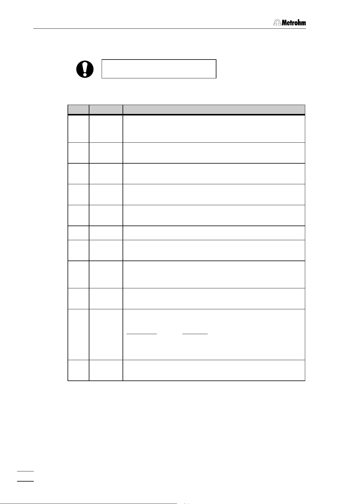
5 Appendix
5.3 Standard equipment
Subject to changes !
The 2.750.0010 Autosampler includes the following parts:
Quant. Order No. Description
1 6.1803.000 PTFE Microcapillary tubing
Transfer tubing for connection of transfer needle with injection valve;
i.D. = 0.3 mm, e.D. = 1.5 mm, length = 1 m
1 6.2041.600 Sample rack
For 128 sample vials
1 6.2128.100 Connecting cable
Connecting cable 750 Autosampler– 733 IC Separation Center
1 6.2140.010 Connector plug
With 19 connections, plugs into contact closure strip 1010
1 6.2140.020 Connector plug
With 8 connections, plugs into contact closure strip 99
1 6.2621.020 Open-end spanner 7⁄⁄32"
1 6.2742.010 Dust cover
Dust cover for Autosampler 750
1 6.2743.000 Polypropylene (PP) sample vials
Set of 1000, with 1000 stoppers (transparent) and
100 stoppers (colored) made of polyethylene
1 6.2744.010 PEEK compression fitting
Set of 5, for connection of 6.1803.000 PTFE microcapillary tubing
1 6.2122.0X0 Mains cable
to customer's specifications:
Cable socket Cable plug
Type IEC 320/C 13 Type SEV 12 (CH…)............................... 6.2122.020
Type IEC 320/C 13 Type CEE (7), VII (D…)........................... 6.2122.040
Type CEE (22), V Type NEMA 5-15 (USA…) ......................6.2122.070
1 8.750.1023 Instructions for Use (English)
for 750 Autosampler
54
750 Autosampler
Page 58

5.4 Optional accessories
Order No. Description
6.2134.000 RS Connecting cable
length = 2 m; plug = 9-pol male / 9-pol female
6.2115.070 Connecting cable 750 – 733
length = 1.4 m
6.2134.070 Connecting cable 750 – 709
length = 2 m
6.2620.130 Transfer needle
Replacement needle, assembly see chap. 4.2.2
6.2413.000 Borosilicate glass sample vials
Set of 1000, with 1000 stoppers (transparent) and
100 stoppers (colored) made of polyethylene
6.2743.010 Polyethylene (PE) stoppers
Set of 1000, transparent
5.4 Optional accessories
6.2743.020 Polyethylene (PE) stoppers
Set of 1000, colored
6.2743.030 Filter stoppers (FilterCaps)
Set of 100, for automatic sample filtering
750 Autosampler
55
Page 59

5 Appendix
5.5 Warranty and conformity
5.5.1 Warranty
The warranty on our products is limited to defects that are traceable to
material, construction or manufacturing error which occur within 12
months from the day of delivery. In such cases the defects will be rectified in our workshops free of charge. Transport costs are to be paid by
the customer.
For day and night operation the warranty is limited to 6 months.
Glass breakage in the case of electrodes or other parts is not covered
by the warranty. Checks which we are asked to carry out during the
warranty period for reasons other than material or manufacturing faults
will be invoiced. For parts manufactured by third parties, insofar as
these constitute an appreciable part of our instrument, the warranty
stipulations of the manufacturer in question apply.
With the regard to the guarantee of accuracy, the technical specifications in the instruction manual are authoritative.
With regard to defects in material, construction or design as well as the
absence of guaranteed features, the purchaser has no rights or claims
except those mentioned above.
If damage of the packaging is evident on receipt of a consignment or if
the goods show signs of transport damage after unpacking, the carrier
must be informed immediately and a written damage report demanded.
Lack of an official damage report releases Metrohm from any liability to
pay compensation.
If any instruments and parts have to be returned, the original packaging
should be used if at all possible. This applies above all to instruments,
electrodes, burette cylinders and PTFE pistons. Before embedding
them in wood shavings or similar material, the parts must be packed in
a dustproof package (for instruments the use of a plastic bag is imperative). If open assemblies are enclosed in the scope of delivery that
are sensitive to electromagnetic voltages (e.g. data interfaces etc.)
these must be returned in the associated original protective packaging
(e.g. conductive protective bag). (Exception: assemblies with built-in
voltage source belong in a non-conductive protective packaging). For
damage which arises as a result of non-compliance with these instructions, no warranty responsibility whatsoever will be accepted by
Metrohm.
56
750 Autosampler
Page 60

5.5.2 EU Declaration of conformity
EU Declaration of Conformity
The METROHM AG company, Herisau, Switzerland hereby certifies, that the instrument:
750 Autosampler
meets the requirements of EC Directives 89/336/EWG and 73/23/EWG.
5.5 Warranty and conformity
Source of the specifications:
EN 50081-1 Electromagnetic compatibility, basic specification
Emitted Interference
EN 50082-1 Electromagnetic compatibility, basic specification
Interference Immunity
EN 61010 Safety requirements for electrical equipment for
measurement, control and laboratory use
Description of the instrument:
Autosampler for ion chromatography
Herisau, November 8, 1996
750 Autosampler
Dr. J. Frank Ch. Buchmann
Development Manager Production and
Quality Assurance Manager
57
Page 61

5 Appendix
5.5.3 Certificate of conformity and system validation
Certificate of Conformity and System Validation
This is to certify the conformity to the standard specifications for electrical appliances and accessories, as well as to the standard specifications for security and
to system validation issued by the manufacturing company.
Name of commodity: 750 Autosampler
Name of manufacturer: Metrohm Ltd., Herisau, Switzerland
System software: Stored in ROMs
Principal technical information: Voltages: 100…120, 230…240 V
Frequency: 50…60 Hz
This Metrohm instrument has been built and has undergone final type testing
according to the standards:
EN55011 (class A), EN50082-1 — Electromagnetic compatibility
IEC1010, EN61010, UL3101-1 — Security specifications
It has also been certified by the Swiss Electrotechnical Association (SEV), which
is member of the International Certification Body (CB/IEC).
The technical specifications are documented in the instruction manual.
The system software, stored in Read Only Memories (ROMs) has been validated
in connection with standard operating procedures in respect to functionality and
performance. The features of the system software are documented in the instruction manual.
Metrohm Ltd. is holder of the SQS-certificate of the quality system ISO 9001 for
quality assurance in design/development, production, installation and servicing.
Herisau, November 8, 1996
58
Dr. J. Frank Ch. Buchmann
Development Manager Production and
Quality Assurance Manager
750 Autosampler
Page 62

5.6 Index
5.6 Index
7
732 IC Detector as "Master" ................ 11
750 Autosampler as "Master" ..............10
A
Accessories......................................... 54
Acoustic signal.................................... 25
Ambient temperature........................... 50
Analysis time .......................................30
Append program step......................... 31
Append Step......................................... 31
Appendix .............................................49
Arrows ................................................. 19
Audible beep ....................................... 25
Audible Key Feedback Selection ...........25
B
Baud rate........................................ 36,53
Buffered samples ................................42
C
Cable (6.2115.070).............................. 55
Cable (6.2128.100)............... 10,11,12,54
Cable (6.2134.000)......................... 12,55
Cable (6.2134.070).............................. 55
Capacity ..............................................49
Carryover............................................. 49
Caution.................................................. 7
Centering sleeve 2424
Figure ..............................................42
Certificate of conformity
and system validation...................... 58
Check .................................................... 9
Clamping ring 2222
Figure ..............................................42
CLOSURE DURATIONS......................... 24
COM.................................................... 23
Comment............................................... 7
Connection of 709 IC Pump........... 10,12
Connection screw 2121
Figure ..............................................42
Replace transfer needle ..................41
Connection to 762 with «IC Net».......... 12
Connection to IC system ..................... 10
Connection to injection valve............... 14
Connector plug (6.2140.010) .... 10,11,54
Connector plug (6.2140.020)10,11,12,54
Contact closure strip 99
Description ......................................51
Figure ................................................5
Insert connector plug ............ 10,11,12
Contact closure strip 1010
Contact closure times...................... 23
Description ......................................51
Figure ................................................5
Insert connector plug ................. 10,11
Contact closure time for "START"........ 24
Contact closure time for "T1"............... 24
Contact closure time for "T2"............... 24
Contact closure time for "T3"............... 24
Contact closure times ............... 23,51,52
Contact Closures.................................. 23
Control elements................................... 4
Control of external instruments ........... 23
Copy a method ................................... 32
Copy Method........................................ 32
Corrosion............................................. 42
Cursor keys ............................... 19,20,22
D
Data bits......................................... 37,53
Date/time settings ...............................25
Dead volume.................................... 9,43
Declaration of conformity .................... 57
Delete.................................................. 22
Delete a method.................................. 33
Delete Method ...................................... 33
Delete program step ........................... 32
Delete Step........................................... 32
Depth ..............................................24,50
Dimensions ......................................... 50
Displacement principle ......................... 2
Displacement volumes................ 3,24,27
Display 11
Description...................................... 19
Figure ................................................ 4
Ready for use display...................... 16
Display Method Use.............................. 33
Display of date and time ..................... 25
Display of programmed methods ....... 33
Dust cover (6.2742.010)...................... 54
E
Earthing............................................ 8,16
Edit Method.......................................... 28
Edit program step ............................... 29
Edit Step .............................................. 29
Electrical safety ..................................... 8
Electromagnetic compatibility............. 50
EMC .................................................... 50
Emitted interference ............................ 50
Enter key ............................................. 21
Enter Loop Size.................................... 24
Enter Method Number............ 28,32,33,34
Enter Rinse Vial.................................... 26
Enter Step Number ..........................29,31
Entry error messages.......................... 45
Entry of loop size................................. 24
Entry of needle depth.......................... 24
Error messages.............................. 19,45
EU Declaration of conformity ..............57
Event 1................................................. 24
Event 2................................................. 24
Event 3..................................................24
Event1 Time ..........................................30
Event2 Time ..........................................30
Event3 Time ..........................................30
Exit .......................................................19
External injection start..........................30
External start ........................................52
F
Faults ...................................................39
Ferrule 1616
Figure...............................................42
Replace transfer needle...................41
Filling of 2 sample loops......................14
Filter stopper
(6.2743.030).......24,25,27,29,40,44,55
FilterCaps..................... see Filter stopper
Filtration ..........................................39,42
Final Vial...............................................29
First sample vial ...................................29
Front.......................................................4
Function key.........................................21
Fundamentals of operation..................19
Fuse cassette 1515
Change fuses...................................15
Figure.................................................5
Fuse holder ..........................................15
Fuses ..............................................15,49
H
Handling of solvents ..............................8
Hazard ...................................................7
Height...................................................50
Holder 66
Figure.................................................4
Installation ........................................14
Holder 2020
Figure...............................................42
Holder 2323
Figure...............................................42
Holder stopper 77
Figure.................................................4
Installation ........................................14
Home position......................................23
Housing................................................50
I
Immunity to interference.......................50
Information on the
Instructions for Use............................6
Initial checkout .....................................17
Injection...........................................24,26
Injection Valve..................................25,45
Injection valve leak...............................44
Injection volume.....................................3
Injections ..............................................29
Inputs ...................................................51
750 Autosampler
59
Page 63

5 Appendix
Insert program step............................. 31
Insert Step............................................ 31
Installation .............................................9
Installation problems ...........................17
Instructions for Use (8.750.1023)..... 6,54
Instrument description........................... 1
Instrument dialog................................. 19
Interfaces........................................49,51
Introduction............................................1
Irreproducibility....................................43
K
Key beep ..............................................25
Key for priority sample......................... 21
Key functions.......................................20
Keypad 22
Figure ................................................4
Technical data................................. 49
Keys
<CLEAR>....................................... 22
<down>.......................................... 22
<ENTER>.......................................21
<FUNCTION> ................................ 21
<left>.............................................. 22
<MANUAL INJECTION> ........... 21,26
<METHOD>.............................. 21,28
<PRIORITY>.............................. 21,35
<REM/LOC> ............................. 21,36
<right> ...........................................22
<RINSE>................................... 21,26
<RUN/STOP> ...........................21,34
<SYSTEM> ...............................21,23
<up> ..............................................22
L
Last sample vial................................... 29
Leaks ................................................ 8,43
Loading sample vials...........................39
Local ....................................................36
Location................................................. 9
Loop Size ........................................24,49
M
Main function keys............................... 20
Main screen.........................................19
Mains cable
Mains connection ............................16
Ordering designation....................... 54
Mains connection
Procedure........................................ 15
Safety notes.......................................8
Technical data................................. 49
Mains connection plug 1414
Figure ................................................5
Mains connection ............................16
Mains frequency.................................. 15
Mains switch 1313
Figure ................................................5
Switching the instrument on/off ....... 16
Mains voltage ...................................... 15
Maintenance...................................39,41
Malfunctioning injection valve..............45
Malfunctions ........................................ 43
Manual injection .............................21,26
Manual injection completed ................ 27
Manual injection running ..................... 27
<MANUAL INJECTION>.................... 26
Manual rinsing..................................... 26
Manual sample filtering ....................... 39
Membrane filter ................................... 39
Memory place...................................... 33
Menu ................................................... 19
Menu for priority sample...................... 35
<METHOD>....................................... 28
METHOD COMPLETED .........................34
METHOD MENU.................................... 28
Method procedure............................... 34
METHOD STOPPED.............................. 34
Method storage display....................... 33
Methods .............................................. 28
Missed injections................................. 44
Model plate 1212
Figure ................................................5
Mount seals......................................... 44
N
NC .......................................................23
Needle depth.................................. 24,27
Needle Depth........................................ 27
Needle holder 1717
Figure ..............................................42
Replace transfer needle ..................41
Needle position .....................................3
Needle settings ................................... 24
Needle Setup........................................ 24
Next program step .............................. 31
Next Step.............................................. 31
NO....................................................... 23
Non-reproducible injections ................ 43
Normal closed..................................... 23
Normal open........................................ 23
Normal operation................................. 36
Normal Rinse......................................... 3
Notations............................................... 7
Number of injections ................... 3,29,49
Numerical keys............................... 19,20
Numerical parameter values ...............19
Nut 1919
Figure ..............................................42
Replace transfer needle ..................41
O
Open-end spanner (6.2621.020)......... 54
Opening the 750 Autosampler ..............8
Operating information ......................... 39
Operating parameters......................... 40
Operation ............................................ 19
Operation interruption ......................... 52
Optional accessories........................... 55
Output "START" ................................... 23
Output "T1" ..................................... 23,30
Output "T2" ..................................... 23,30
Output "T3" ..................................... 23,30
Outputs................................................ 51
P
Packaging ............................................. 9
Parameter............................................ 19
Parity .............................................. 36,53
Park Needle.......................................... 23
Particulate matter ................................ 39
PEEK compression fitting 1818
Figure.............................................. 42
Installation ....................................... 14
Ordering designation ...................... 54
Pictograms............................................ 7
Plugged tubing.................................... 43
Plugging............................... 39,42,43,44
Poorly swaged fittings......................... 43
Position of rinsing solution .................. 26
Position of sample vial ........................ 26
Power consumption ............................ 49
Precautionary rules................................ 8
Precipitation ........................................ 42
Pressure .............................................. 25
Pressure for needle lowering............... 25
Previous program step........................ 31
Previous Step....................................... 31
<PRIORITY> ...................................... 35
PRIORITY SAMPLE.............................. 35
Priority sample..................................... 35
Program step menu ............................ 28
Program version.................................. 25
Programmed method.......................... 33
PROGRAMMED METHODS ................... 33
Programs.............................see Methods
Protection class................................... 16
Protective earth ................................... 16
PTFE capillary tubing
...........................see Transfer tubing 88
Q
Quick Rinse................................. 3,30,31
R
Rear....................................................... 5
<REM/LOC>...................................... 36
Remedying malfunctions..................... 43
Remote control............................... 36,48
Remote control commands................. 38
Remote control error codes ................ 48
Remote control mode.......................... 37
Remote-controlled operation............... 36
Reset ................................................... 22
Retention time ..................................... 40
Return to basic condition .................... 19
<RINSE>............................................ 26
Rinse process ....................................... 3
Rinse Type ........................................... 30
Rinse vials ............................................. 3
Rinsing ..................................... 2,3,30,31
Rinsing vial.......................................... 30
RS-232 ................................................. 36
60
750 Autosampler
Page 64

5.6 Index
RS232 interface 1111
Connection to 762........................... 12
Description ......................................53
Figure ................................................5
Remote control ................................ 36
Run Injection ........................................27
Run Method.......................................... 32
Run Time.............................................. 30
<RUN/STOP> ....................................34
Run/Stop key....................................... 21
Running a method............................... 32
S
Safety notes...................................... 8,50
Safety specifications ........................... 50
Sample carryover ..................................2
Sample filtering.................................... 39
Sample injection.................................... 2
Sample loop .......................................... 3
Sample preparation........................ 39,42
Sample rack 33
Easy access .................................... 23
Figure ................................................4
Ordering designation....................... 54
Position of rinsing solution............... 26
Sample series...................................... 29
Sample transfer ..................................... 2
Sample Vial ..........................................26
Sample vial 44
Figure ................................................4
Ordering designation....................... 54
Sample vial position ............................26
Sampling ............................................. 49
Seals.................................................... 43
SELECT A FUNCTION........................... 19
Select Baud Rate ..................................36
Select Data Bits.................................... 37
Select method ...................... 28,32,33,34
Select Parity......................................... 36
Select program step....................... 29,31
Select Stop Bits.................................... 37
Servicing.............................................. 41
Set Date ............................................... 25
Set Time............................................... 25
Setting up the instrument ...................... 9
Shipping position ................................ 22
Skipped vials....................................... 44
Solids .................................................. 42
Source method.................................... 32
Standard chromatogram..................... 17
Standard equipment ........................... 54
Start Vial .............................................. 29
Static charges ....................................... 8
Status................................................... 25
Status display...................................... 25
Status display for method ...................34
Status display for priority sample........ 35
Steel capillary...................................... 44
Stop bit................................................ 53
Stop bits.............................................. 37
Stop signal ..........................................52
Stopper
Filter stopper (6.2743.030).............. 40
Function .......................................... 39
Stopper (6.2743.010) .......................... 55
Stopper (6.2743.020) .......................... 55
Submerged waste tube....................... 44
Switching the instrument on/off........... 16
<SYSTEM>........................................ 23
System error messages ...................... 47
System parameters............................. 21
System settings................................... 23
SYSTEM SETTINGS.............................. 23
T
Target method......................................32
Technical data......................................49
Theory of operation................................2
Time for event T1 .................................30
Time for event T2 .................................30
Time for event T3 .................................30
Time/Date..............................................25
Title.......................................................19
Transfer needle 55
Connect transfer tubing ...................14
Figure............................................4,42
Home position..................................23
Ordering designation .......................55
Replacement....................................41
Theory of operation............................2
Transfer needle replacement ...............41
Transfer tubing 88
Figure.................................................4
Installation ........................................14
Ordering designation .......................54
Plugging...........................................43
Theory of operation............................2
Transport..............................................50
Transport damage ..........................17,56
Tubing connection ...............................14
V
Valve control.........................................51
Vial .......................................................39
W
Warning..................................................7
Warranty...............................................56
Waste container ...................................14
Weight..................................................50
Width....................................................50
750 Autosampler
61
Page 65

5 Appendix
62
750 Autosampler
 Loading...