

Page 1

CH-9101 Herisau/Switzerland
Phone +41 71 353 85 85
Fax +41 71 353 89 01
EMail sales@metrohm.ch
Internet http://www.metrohm.ch
748 DH Sample Changer
Instructions for Use
8.748.1003
99.01 mst, ti
Page 2

Contents
Contents
1 Introduction..............................................................................................................2
1.1 Overview....................................................................................................................... 2
1.2 Sample arm positions .................................................................................................. 4
1.2.1 Positions in the XY-direction ................................................................................. 4
1.2.2 Positions in the Z-direction.................................................................................... 4
2 Sample changer start-up.........................................................................................5
2.1 Mains voltage, mains connection................................................................................ 5
2.2 Sample Changer setup................................................................................................ 6
2.2.1 Setting up the basic instrument ............................................................................ 6
2.2.2 Installation of rinsing accessories......................................................................... 7
2.3 Equipping the titration head......................................................................................... 8
2.4 Sample racks................................................................................................................ 9
2.5 Sample Changer start up............................................................................................. 9
2.6 Adjusting Sample Changer.......................................................................................... 9
3 Operation via RS232 Interface ..............................................................................11
3.1 General rules .............................................................................................................. 11
3.1.1 Tree of commands .............................................................................................. 11
3.1.2 Triggers................................................................................................................ 11
3.2 Remote control commands ....................................................................................... 12
3.2.1 Overview .............................................................................................................. 12
3.2.2 Description of the remote control commands.................................................... 13
3.3 Properties of the RS 232 Interface............................................................................. 16
4 Troubleshooting, remedying faults ......................................................................17
4.1 Troubleshooting ......................................................................................................... 17
4.2 TiNet error messages................................................................................................. 18
4.3 Readjust Sample Changer......................................................................................... 19
5 Appendix.................................................................................................................20
5.1 Technical specifications............................................................................................. 20
5.2 Sample Changer methods......................................................................................... 21
5.3 Pin assignment of I/O sockets "Auxiliary" .................................................................. 22
5.4 Warranty and certificates............................................................................................ 23
5.4.1 Warranty............................................................................................................... 23
5.4.2 Certificate of Conformity and System Validation................................................ 24
5.5 Scope of delivery, accessories .................................................................................. 26
Index ..........................................................................................................................29
748 DH Sample Changer
Page 3
1 Introduction
1.1 Overview
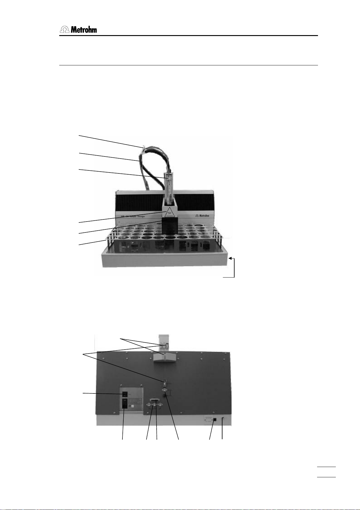
Instrument front panel:
1
2
3
1.1 Overview
4
5
6
Instrument rear panel:
8
9
10
7
748 DH Sample Changer
11 13 14
12
15
16
1
Page 4

1.1 Overview
Instrument front panel:
1 6.2053.010 cable/tubing clamps
2 Control cable
assembly see page 6.
3 Cable/tubing holder
4 Sample arm
5 Splash protection
6 Sample rack
for 48 x 250 mL beakers
or
for 136 x 75 mL beakers
7 Connection for waste tubing
2
748 DH Sample Changer
Page 5

Instrument rear panel:
8 Holder for control cable
9 Sockets for control cable
10 Mains switch
11 Connection for mains cable
Mains voltage adjustment: see page 5.
In networks where the mains voltage is subject to strong HFinterference the Sample Changer should be operated with an additional
mains filter, e.g. Metrohm 615 mains filter.
12 Remote sockets for I/O lines
The beaker detector is plugged into remote socket 1.
Remote sockets 2 and 3 can be used for connecting external instruments. The lines can be activated from TiNet (see TiNet Instructions for
Use).
1.1 Overview
13 RS232 interface
for connecting a computer
14 Stirrer connection and setting the stirrer speed
Rod stirrer 722
Supply voltage: 10 VDC (I ≤ 200 mA)
15 Voltage adjustment for pump
see page 5
16 Connection for rinsing tubing
with 6.1808.050 tubing nozzle
748 DH Sample Changer
3
Page 6
1.2 Overview
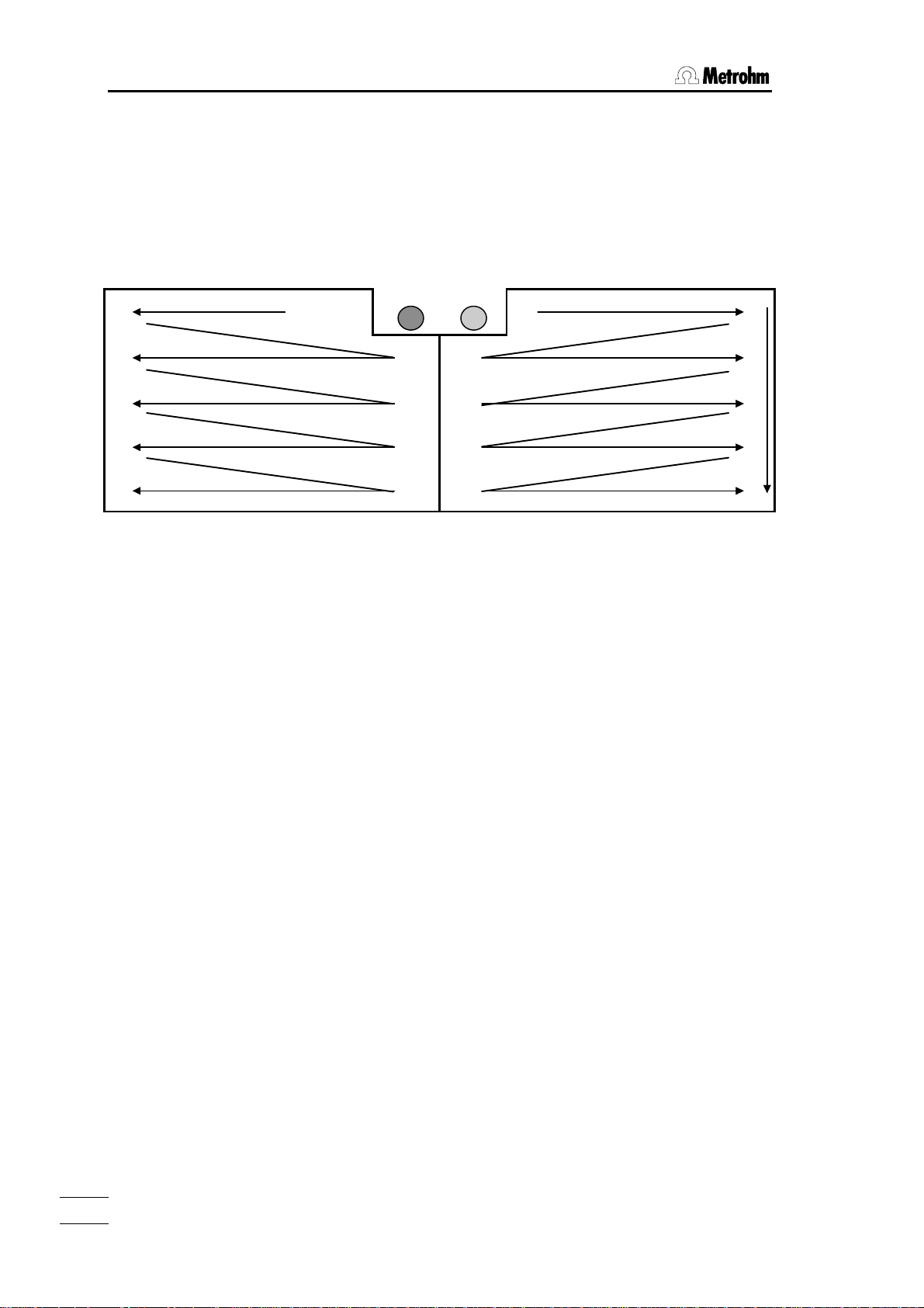
Y-
1.2 Sample arm positions
The sample arm is moved in both the XY-direction (rack positions) as
well as in the Z-direction.
1.2.1 Positions in the XY-direction
Left-hand rack Right-hand rack
1 Wash Soak Home
X-direction
direction
The sample arm is moved so that it only moves above samples which
have already been titrated (i.e. positions which have already been visited).
1.2.2 Positions in the Z-direction
The positions in the Z-direction are set in the TiNet configuration. They
are given in mm: measurements are made from the tower; the zero
point is 15 mm below the upper edge.
The positions in the Z-direction depend on both the type of rack used
and on the sample head fittings.
Working position
Position during titration/measurement.
The beaker detector should stand on the beaker rim.
Take care that electrodes, stirrer and buret tips are sufficiently immersed.
Rotation position, movement position
Position during the movement of the sample arm in the XY-direction.
Take care that electrodes, stirrer and buret tips are raised higher than
the beaker rims.
Rinsing position
Position during rinsing in the wash beaker.
Take care that electrodes, stirrer and buret tips are well located in the
rinsing spray of the wash beaker.
4
748 DH Sample Changer
Page 7

2.1 Mains voltage, mains connection
2 Sample changer start-up
2.1 Mains voltage, mains connection
Check that the voltage set on the instrument corresponds
to your mains voltage. If this is not the case then the mains
voltage must be altered:
1. Remove the mains cable.
2. Carefully open the compartment above the mains cable
with a screwdriver.
3. Remove the voltage selection drum.
4. If necessary change the fuse: remove the parts marked
with "⇒" and insert the fuses for the corresponding voltage which are given on the rear panel of the instrument.
5. Rotate the voltage selection drum so that the correct
voltage appears at the front (when the compartment is
closed this voltage will appear in the window).
6. Close the compartment again.
Set mains voltage for pump
1. Screw off the cover for the pump voltage setting (foldout page, position 15).
2. Adjust the tumbler switch so that your approximate
mains voltage appears:
220...240 V: switch display 230 V
100...120 V: switch display 115 V
3. Change the fuse if necessary.
4. Screw on the cover again so that the marking with the
set voltage is on the outside.
The mains cable supplied with the instrument is a 3-core
cable fitted with a plug with an earthing pin. If a different
plug must be used then the yellow/green lead must be
connected to the protective earth. Any break in the earthing
inside or outside the instrument can turn it into a hazard.
When the instrument is opened or if parts of it are removed
then certain components may be live if the instrument is still
connected to the mains. This means that the mains cable
must always be unplugged when certain adjustments are
made or when parts are replaced.
748 DH Sample Changer
The cable should only be plugged in and unplugged when
the instrument is switched off.
5
Page 8
2.2 Sample Changer setup
2.2 Sample Changer setup
2.2.1 Setting up the basic instrument
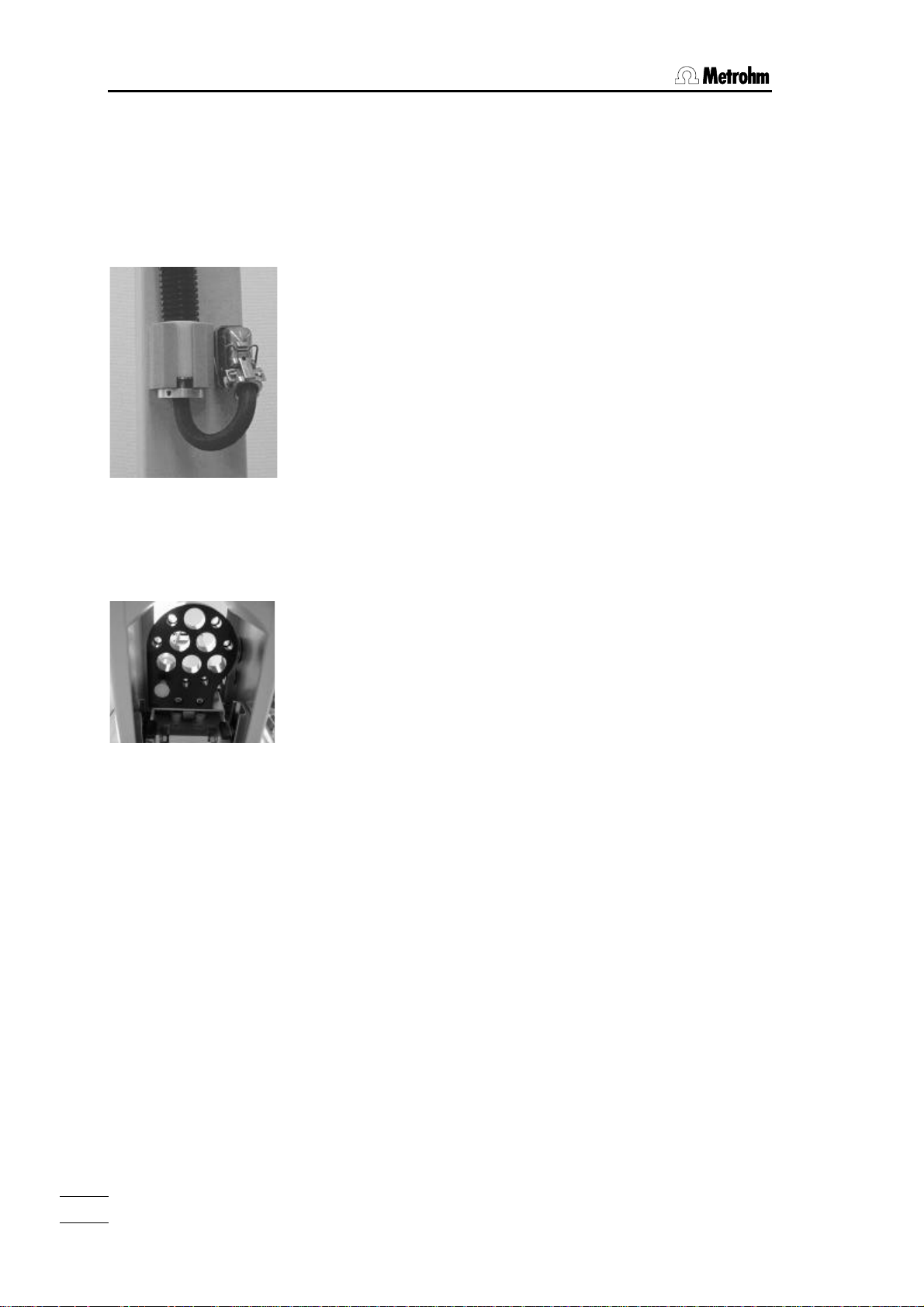
Attaching the
control cable:
Fastening the titration head,
sample arm from below:
Important:
Do not lift the sample changer by the sample arm.
Check the delivery immediately on receipt for completeness and transport damage.
Setup
1. Attach control cable to sample arm: insert the white
sleeve with the washer in the cable holder and screw
the holding ring tight (with 1.5 mm Allen key).
Insert cable and secure with clip.
2. Attach and insert the control cable on the rear panel
of the sample changer in the same way.
3. Clip 6.2053.010 cable clamps onto the control cable.
4. Remove splash protection: screw off the 2 sidemounted Phillips screws and carefully pull off plastic
panel.
5. Screw the titration head into the titration head holder
of the sample arm from below (3 mm Allen key)
6. Lead the beaker detector cable through the cable
holder and through the cable clamps to the rear panel
of the sample changer.
7. Connect the beaker detector cable to remote socket
"Auxiliary 1".
8. Reattach splash protection: set place plastic part in
position and screw on again.
6
748 DH Sample Changer
Page 9

2.2.2 Installation of rinsing accessories
1. Screw 6.1808.050 tubing nozzle for the rinsing tubing
onto the rear panel of the Sample Changer (fold-out
page, Position 16).
2. Attach the rinsing tubing (thin 6.1801.120 PVC tubing)
to the tubing nozzle. Use tubing clamps to attach
tubing firmly.
3. Pull the nut of the small opening of the canister over
the rinsing tubing.
4. Push the other end of the rinsing tubing onto
6.1828.000 connection nipple and screw it tight.
5. Push 6.1812.010 PTFE tubing onto the other end of
the connection nipple (heat up tubing end, hold tubing firmly with abrasive paper) and screw it tight.
6. Screw rinsing tubing onto the rinsing canister and fill
the rinsing canister with rinsing solution (water).
7. Push 6.1801.130 PVC tubing onto the right-hand side
of the Sample Changer (fold-out page, Position 7).
8. Attach other end of tubing to 6.1828.010 tubing nozzle.
9. Screw tubing nozzle onto the waste canister.
2.2 Sample Changer setup
Important
• The waste tubing must not sag.
• Do not seal the canister hermetically (pressure com-
pensation, backwater in the wash beaker!).
• Regularly check the filling levels of the rinsing and
waste canisters!
• The rinsing device is only suitable for use with aqueous solutions.
If you have to rinse with organic solvents then you can
clean the inserts by "immersion in a rinsing beaker".
748 DH Sample Changer
7
Page 10
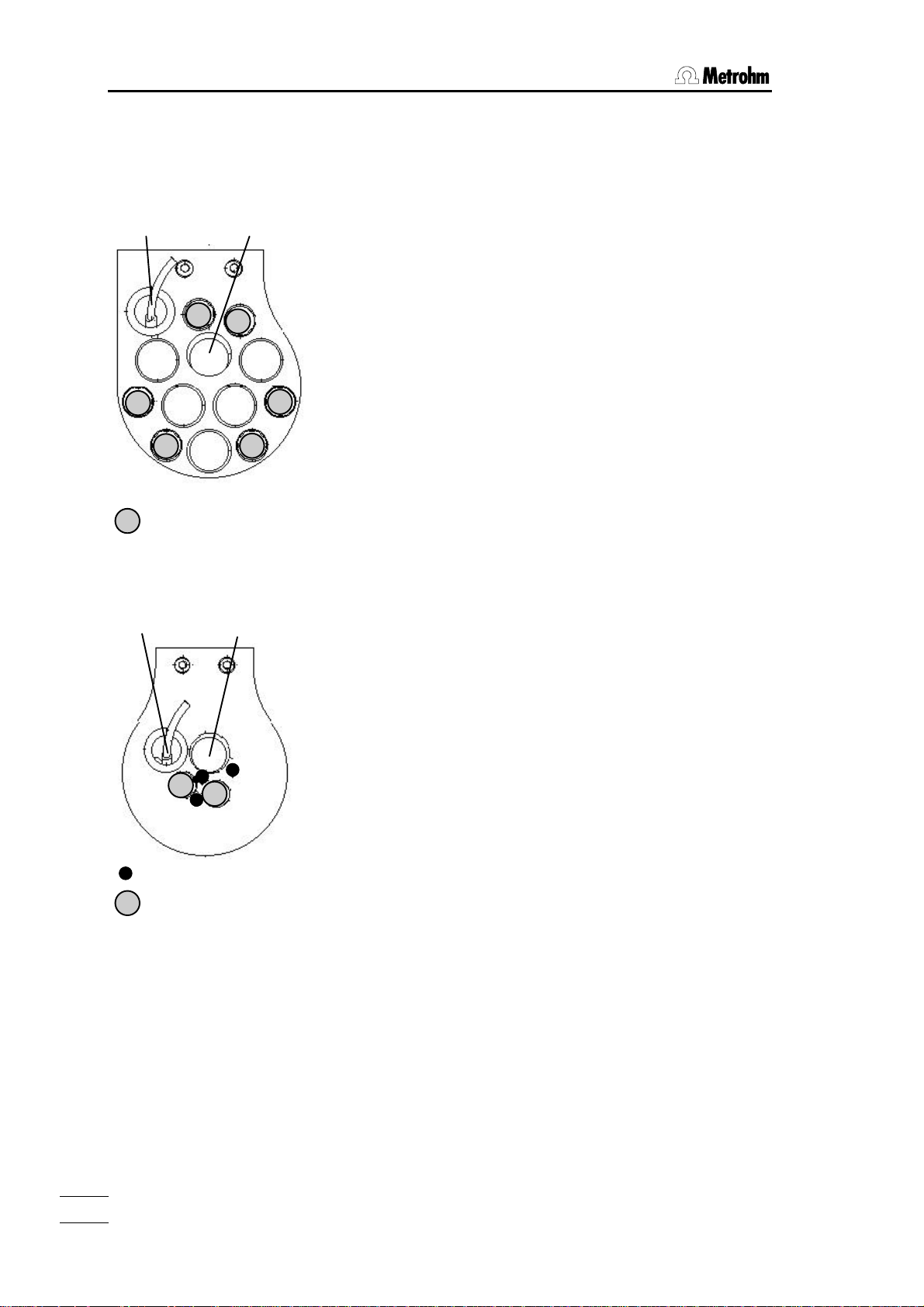
2.3 Equipping the titration head
titration head:
2.3 Equipping the titration head
6.1463.000 Macro
titration head:
Beaker detector
M10 screw threads for buret
tips
Stirrer
6.1463.010 Micro
Beaker detector
Stirrer
2.722.0020 Rod stirrer
1. Insert stirrer in titration head.
2. Lead stirrer cable through cable holder and through the
cable clamps to the rear panel of the Sample Changer.
3. Connect cable to stirrer socket "Mixer".
4. Push 6.1909.020 stirrer propeller onto the stirrer from
below.
5. The stirrer speed can be set with the rotary switch on the
rear panel of the Sample Changer.
Electrodes (see also page 27
6.1463.000 macro titration head: electrodes with SGJ 14/15
6.1463.010 micro titration head: micro electrodes, 6 mm di-
ameter.
1. Insert electrode into titration head.
2. Screw electrode cable (at least 2 m long) onto electrode
plug head and lead it through the cable holder and the
cable clamps to the rear panel of the Sample Changer.
3. Plug electrode cable into Titrator.
Buret tips
1. Insert buret tips into titration head and screw tight with
M10 screw threads.
2. Screw 6.1805.XXX tubing connection onto the buret tips.
3. Lead tubing through the tubing holder and the tubing
clamps to the rear panel of the Sample Changer.
4. Connect the other end of the tubing to the dosing unit
outlet. Use 6.1808.000 connection piece for connecting
to the dosing tubing if necessary.
Important
The cable and tubing should be led between the cable/tubing holder and the cable/tubing clamps in a curve so
Built-in buret tips
M10 screw threads for
electrodes or further buret
tips
that they are not subjected to stress when the titration head
is lowered!
Check length of cables and tubings as follows:
• Open Sample Changer window in the titration part of TiNet.
• Press button <Ctrl>.
• Move to "Home" position and lower the sample arm to
working position.
8
748 DH Sample Changer
Page 11

2.4 Sample racks
Place sample racks in position.
Place 6.1432.320 sample beaker in the soak position (see
page 4).
Use 6.2060.000 holders to carry the racks.
2.5 Sample Changer start up
Connect the RS232 interface of the Sample Changer with a
COM of the computer:
Cables:
25-pole / 9-pole, 3 m.............................................6.2125.110
25-pole / 25-pole, 3 m...........................................6.2125.060
Extension cable 25-pole / 25-pole, 3 m................ 6.2125.020
Extension cable 9-pole / 9-pole, 3 m.................... 6.2134.110
Start TiNet on the computer and configure the Sample
Changer; see TiNet Instructions for Use.
2.4 Sample racks
2.6 Adjusting Sample Changer
The offset settings for new instruments are determined by
Metrohm. Each Sample Changer is supplied with a document containing these data.
Entering the offset data in TiNet
1. Start the program "Iniedit.exe" from the TiNet bin directory.
2. Under "Various" you will find "Offset 748".
3. Enter the values for X and Y.
4. Press <Apply>.
5. Close the program "Iniedit.exe" and start TiNet (again).
748 DH Sample Changer
9
Page 12

Page 13

3 Operation via RS232 Interface
3.1 General rules
The DH Sample Changer has a remote control facility that allows its control
via TiNet. The parameters of the Sample Changer may be easily set by the
method editor of TiNet.
The following description offers special possibilities of low level control via
the transfer command of the calculation block of the TiNet method editor.
3.1.1 Tree of commands
The commands are hierarchically ordered with the following rules:
Rules Example
The root of the tree is designated by &.
The branches (levels) of a tree are marked with
a dot (.) when calling up an object.
3.1 General rules
Upper- or lowercase letters may be used. &STIRER.ON or &Stirer.On
An object can be assigned a value. Values are
marked at the beginning and end by quotes (").
They may contain ASCII characters or numerical values.
The current object remains valid until a new
object is called.
New objects can be addressed relative to the
old object:
A preceding dot leads forwards to the next level
in the tree.
More than one preceding dot leads one (or
several) level(s) backwards in the tree. n node
backwards require n+1 preceding dots.
If you want to jump back to the root, enter a
preceding &.
&Stirer.On"True"
&Init.SpeedXY"3"
&Stirer.On"True";..$G
Leads back from nod &Stirer.On to nod &Stirer
3.1.2 Triggers
$G Go Commands are executed with $G.
Example:
&Stirer.On"True" Sets command.
..$G Starts stirrer.
748 DH Sample Changer
11
Page 14

3.2 Remote control commands
3.2 Remote control commands
3.2.1 Overview
Object Description Input range Reference
& Root
à Stirer Stirrer control $G 3.2.2.1.
³ Ã .On Switching stirrer True, False ditto
³
à GoTo Go to position $G 3.2.2.2.
³ Ã .Vessel Designation of vessel special ditto
³
à GoAbove Go to position $G 3.2.2.3.
³ Ã .Vessel Designation of vessel special ditto
³
à GoIn Go into vessel $G 3.2.2.4.
³ Ã .Vessel Designation of vessel special ditto
³
à GoToHome Goes to home position $G 3.2.2.5.
³
à WashElectrodes Wash electrodes $G 3.2.2.6.
³ Ã .Times Number of wash cycles 1...9999 ditto
³
à SetCtrlLine Setting I/O line $G 3.2.2.7.
³ Ã .On Setting line True, False ditto
³ Ã .Line Selection of line 1...3 ditto
³
à WaitForInput Waiting for input on I/O line $G 3.2.2.8.
³ Ã .On Line state True, False ditto
³ Ã .Line Selection of line 1...3 ditto
³
à Init Setup of Sample Changer $G 3.2.2.9.
³ Ã .SpeedXY Speed in XY direction 0...5...7 ditto
³ Ã .SpeedXYFast Speed in XY direction 0...2...7 ditto
³ Ã .SpeedZ Speed in Z direction 0...3...7 ditto
³ Ã .SpeedZFast Speed in Z direction 0...7 ditto
³ Ã .SpeedZSlow Speed in Z direction 0...7 ditto
³
à StopAll Emergency stop $G 3.2.2.10.
³
à Assembly Basic assembly functions
³ Ã .GoToXYZ Go to postion $G 3.2.2.11.
³ ³ Ã .X X coordinate 0...630 ditto
³ ³ Ã .Y Y coordinate 0...272 ditto
³ ³ Ã .Z Z coordinate 0...120 ditto
³ ³ Ã .SpeedXY Speed in XY direction 0...3...7 ditto
³ ³ Ã .SpeedZ Speed in Z direction 0...3...7 ditto
³ Ã .PumpOn Switching on/off pump True, False, $G 3.2.2.12.
12
748 DH Sample Changer
Page 15

3.2 Remote control commands
3.2.2 Description of the remote control commands
3.2.2.1 Stirer $G
Stirer.On True, False
&Stirer.On"True";..$G Switching the stirrer on.
&Stirer.On"False";..$G Switching the stirrer off.
3.2.2.2 GoTo $G
GoTo.Vessel 1...XXX, Home, Soak, Wash
Makro command which moves to the predefined beaker using the speeds
from branch "Init" (see 3.2.2.9):
- Moves to shift position (set in TiNet configuration), SpeedZSlow
- Moves to beaker position, SpeedXY
- Moves to Z = 0 (as defined in the rack definition file
..\bin\PW74xDef\748*r.def of TiNet) position.
3.2.2.3 GoAbove $G
GoAbove.Vessel 1...XXX, Home, Soak, Wash
Makro command which moves to the predefined beaker (without dipping)
using the speeds from branch "Init" (see 3.2.2.9):
- Moves to shift position (set in TiNet configuration), SpeedZSlow
- Moves to beaker position, SpeedXY
748 DH Sample Changer
3.2.2.4 GoIn $G
GoIn.Vessel 1...XXX, Home, Soak, Wash
Makro command which moves to the lowest possible position in the predefined beaker using the speeds from branch "Init" (see 3.2.2.10):
- Moves to shift position (set in TiNet configuration), SpeedZSlow
- Moves to beaker position, SpeedXY
- Moves to lowest possible Z position, Zmax. (defined in the corresponding
rack definition file), SpeedZ
3.2.2.5 GoToHome $G
Makro command which moves to home position, readjusting the Sample
Changer and using the speeds from branch "Init" (see 3.2.2.9):
3.2.2.6 WashElectrodes $G
WashElectrodes.Times 1...9999
Makro command which moves to wash position position, washes the electrodes and uses the speeds from branch "Init" (see 3.2.2.9):
- Moves up to Z=0, SpeedZ
- Moves to wash position, SpeedXY
- Moves down to wash position, SpeedZ
- Switches pump on
- Moves down to lowest possible position Zmax, SpeedZSlow
- Switches pump off
13
Page 16

3.2 Remote control commands
Ø
- Stirrs during 3 s
- Moves up to Z=0, SpeedZFast
.Times: The number of washing cycles can be set. If the number is >1, the
following additional steps will be carried out (n times); the repetitive steps beginning at the marked position Ø in the sequence:
- Moves up to Z=0, SpeedZFast
- Switches pump on
- Moves down to Zmax., Speed Zslow
- Switches pump off
3.2.2.7 SetCtrlLine $G
A remote control line can be set. Select socket 1...3 and set line as follows:
&SetCtrlLine.On"True";..$G Sets an active line (0 V), see also page 20.
&SetCtrlLine.On"False";..$G Sets the line to inactive (5 V)
The beaker sensor is normally plugged into socket 1.
SetCtrlLine.On True, False
SetCtrlLine.Line 1...3
3.2.2.8 WaitForInput $G
WaitForInput.On True, False
WaitForInput.Line 1...3
The Sample Changer waits for an active line (with WaitForInput.ON"True") or
for an inactive line (with WaitForInput.ON"False"). No other commands are
worked off during this waiting time.
3.2.2.9 Init $G
Init.SpeedXY 0...5...7
Init.SpeedXYFast 0...2...7
Init.SpeedZ 0...3...7
Init.SpeedZFast 0...7
Init.SpeedZSlow 0...7
Sets the global speeds for all makro commands of the Sample Changer. A
small number means a high speed, i.e. 0 is the highest possible speed.
The speeds are only set if the init movement is carried out (command &Init
$G).
&Init $G moves to home position and Z=0.
3.2.2.10 StopAll $G
Emergency stop. Stops all commands immediatelay. May be used e.g. to set
remote control lines to inactive, or to stop stirrer or pump.
14
748 DH Sample Changer
Page 17

3.2 Remote control commands
3.2.2.11 Assembly.GoToXYZ $G
Assembly.GoToXYZ.X 0...630
Assembly.GoToXYZ.Y 0...272
Assembly.GoToXYZ.Z 0...120
Assembly.GoToXYZ.SpeedXY 0...3...7
Assembly.GoToXYZ.SpeedZ 0...3...7
Moves to the predefined position. The above speeds are only valid for Assembly commands.
The extreme positions which are still in the moving range of the Sample
Changer are given in the corresponding rack definition file
(..\bin\PW74xDef\748*r.def of your TiNet program).
You may enter higher valuesfor X, Y, and Z but the Sample Changer has to be
reinitialized after being moved to a position out of ist moving range.
3.2.2.12 Assembly.PumpOn True, False, $G
&Assembly.Pump"True";$G Switching the pump on.
&Assembly.Pump"False";$G Switching the pump off.
748 DH Sample Changer
15
Page 18

3.3 Properties of the RS 232 Interface
3.3 Properties of the RS 232 Interface
The DH Sample Changer is configured as DTE (Data Terminal Equipment).
The RS 232 interface has the following technical specifications:
• Data interface according to the RS 232C standard
• RS232 parameters: 9600 baud
8 data bit
1 stop bit
no parity
SW handshake
• Control characters: C
• Cables 6.2125.060 25/25 pol
(ASCII DEC 13)
R
LF (ASCII DEC 10)
XON (ASCII DEC 17)
XOFF (ASCII DEC 19)
6.2125.110 25/9 pol
length: max. approx. 15 m
16
748 DH Sample Changer
Page 19

4.1 Troubleshooting
4 Troubleshooting, remedying faults
4.1 Troubleshooting
Problem Possible causes and remedies
Beaker detector does not respond
although no beaker is present.
Rack does not fit on Sample Changer. Loosen wash beaker from below the Sample
Rinsing solution does not enter the wash
beaker.
Rinsing solution is not discharged. • Waste tubing must not sag!
Sample arm contacts left or right side. Readjust Sample Changer, see page 19.
Stirrer does not rotate. • Increase stirrer speed. Turn
• Activate beaker detector in program part
"Configuration" of TiNet.
• Is the beaker detector correctly plugged into
the "Auxiliary 1" socket?
Changer, set rack onto Sample Changer and
screw wash beaker back in position.
• The rinsing canister must be open.
• Is the aspiration tubing sufficiently immersed
in the rinsing canister?
• Are all tubing connections tight?
• The waste canister must be open.
counterclockwise until maximum stirrer
speed is reached.
• Try switching on the stirrer in the Sample
Changer window of TiNet, program part
"Titration". If the stirrer rotates then it is
possible that your method does not contain
the command to switch the stirrer on.
• Is the stirrer connected correctly to the
"Mixer" socket?
748 DH Sample Changer
17
Page 20

4.2 TiNet error messages
4.2 TiNet error messages
Problem Possible causes and remedies
Invalid head position selected. A rack position has been selected which is not
contained in the rack definition file.
• Check the selected position.
• Have you selected the correct rack in the
TiNet configuration?
Selected command can't be executed. General communication problem. Exchange
the cable.
There is no beaker. (Position: X) In the TiNet configuration the beaker test is set
to "Display" and no beaker is present in the
given position.
Set the beaker test to "Move" if you want to
move to the next beaker automatically or to
"OFF" if you want to switch off the beaker test.
There is no reply from the Sample
Changer.
Transfer error: the target device cannot
receive data.
Communication interrupted?
• Try to initialize the Sample Changer with the
menu item "Commands, Initialize
instruments" in the titration part of TiNet.
• Reboot computer.
• Switch Sample Changer off/on, make sure
cable is well plugged in and try to initialize
again.
• Does the green lamp light up? If not, check
whether the mains cable is plugged in
correctly. If everything seems to be OK,
change the power supply fuses, see page 5.
• If the green lamp lights up and everything
appears to be OK then change the pump
fuse, see page 5.
• Exchange cable.
Errors if transfer commands from the
calculation block in the method editor are
used:
• Wrong path, value and/or trigger.
• Communication interrupted.
18
748 DH Sample Changer
Page 21

4.3 Readjust Sample Changer
4.3 Readjust Sample Changer
Sample arm from below
with position guide:
Centering ring over rack
bolt:
1. Load the test software from the Internet:
http://www.metrohm.ch
2. Remove the sample racks from the Sample Changer.
3. Install 6.2625.000 position guide on the sample arm instead of the titration head.
4. Place the centering ring over the right-hand side rack
bolt.
5. Start the test software which you have loaded from the
Internet and follow the instructions which you will also
find there.
748 DH Sample Changer
19
Page 22

5.1 Technical specifications
5 Appendix
5.1 Technical specifications
Lift
Max. lift way 146 mm
Max. load 500 g
Sample position precision ± 2 mm
Sample racks 48 beaker, 250 mL
136 beaker, 75 mL
Material Light metal, powder coated
Pump
Capacity 0.33 L/min
Fuse for 100...120 V: T1.25A
for 220...240 V: T630mA L
Housing Al (antichromed) and stainless steel, powder coated
RS232 interface for PC connection
Input/output lines for beaker sensor and any other devices
Ambient temperature
Nom. operation range 0 ... 45 °C
Storage, transport – 25 ... 60 °C
Safety specifications
Designed and tested in accordance to IEC publication
1010-1, safety class I. This manual contains information
and warnings which have to be followed by the user to ensure safe operation and to retain the apparatus in safe
condition.
Mains connection
Voltage 100, 120, 220, 240 V ± 10 % (switchable)
Frequency 50 ... 60 Hz
Power consumption max. 190 VA
Fuses (2) for 100...120 V: T2A/120V
for 220...240 V: T1A/250V
Dimensions
Width 750 mm
Height 750 mm
Depth 600 mm
Weight, incl. accessories ca. 35.5kg
20
748 DH Sample Changer
Page 23

5.2 Sample Changer methods
Methods for TiNet and working with the 748 DH Sample Changer are
available at http://www.metrohm.ch
5.2 Sample Changer methods
748 DH Sample Changer
21
Page 24

5.3 Pin assignment of I/O sockets "Auxiliary"
5.3 Pin assignment of I/O sockets "Auxiliary"
external Function
Input
Output
Ground
0 V
+5 V
pin 2
pin 1 1 A
50 V
non-inductive
0 V
pin 5
22
5-pin DIN plug
No liability whatsoever will be accepted for damage caused by improper interconnection of instruments.
748 DH Sample Changer
Page 25

5.4 Warranty and certificates
5.4.1 Warranty
The warranty regarding our products is limited to rectification free of
charge in our workshops of defects that can be proved to be due to
material, design or manufacturing faults which appear within 12
months from the day of delivery. Transport costs are chargeable to
the purchaser.
For day and night operation, the warranty is valid for 6 months.
Glass breakage in the case of electrodes or other glass parts is not
covered by the warranty. Checks which are not a result of material or
manufacturing faults are also charged during the warranty period.
For parts of outside manufacture insofar as these constitute an appreciable part of our instrument, the warranty stipulations of the
manufacturer in question apply.
With regard to the guarantee of accuracy, the technical specifications in the Instructions for Use are authoritative.
Concerning defects in material, construction or design as well as the
absence of guaranteed features, the purchaser has no rights or
claims except those mentioned above.
If damage of the packaging is evident on receipt of a consignment
or if the goods show signs of transport damage after unpacking, the
carrier must be informed immediately and a written damage report
demanded. Lack of an official damage report releases METROHM
from any liability to pay compensation.
If any instruments and parts have to be returned, the original packaging should be used if at all possible. This applies above all to instruments, electrodes, buret cylinders and PTFE pistons. Before
embedding in wood shavings or similar material, the parts must be
packed in a dustproof package (for instruments, use of a plastic bag
is imperative). If open assemblies are enclosed in the scope of delivery that are sensitive to electromagnetic voltages (e.g. data interfaces etc.) these must be returned in the associated original protective packaging (e.g. conductive protective bag). (Exception: assemblies with built-in voltage source belong in a non-conductive protective packaging). For damage which arises as a result of noncompliance with these instructions, no warranty responsibility whatsoever will be accepted by METROHM.
5.4 Warranty and certificates
748 DH Sample Changer
23
Page 26

5.4 Warranty and certificates
5.4.2 Certificate of Conformity and System Validation
This is to certify the conformity to the standard specifications for
electrical appliances and accessories, as well as to the standard
specifications for security and to system validation issued by the
manufacturing company.
Name of commodity: 748 DH Sample Changer
System software: Stored in ROMs
Name of manufacturer: Metrohm Ltd., Herisau, Switzerland
This Metrohm instrument has been built and has undergone final type testing according to the standards:
Electromagnetic compatibility: Emission
EN50081-1/92, EN55022/class B,
EN55011/class B Generic emission
Electromagnetic compatibility: Immunity
IEC801-2/91, Static discharge
IEC801-3, IEC1000-4-3 Radiated rf electromag.field immunity
EN61000-3-2/95 Harmonic current
Security specifications
IEC1010 class1, EN61010 class1, UL3101-1
The technical specifications are documented in the instruction manual.
The system software, stored in Read Only Memories (ROMs) has
been validated in connection with standard operating procedures in
respect to functionality and performance.
The features of the system software are documented in the instruction manual.
Metrohm Ltd. is holder of the SQS certificate of the quality system
ISO 9001 for quality assurance in design/development, production,
installation and servicing.
Herisau, October 14, 1998
Dr. J. Frank Ch. Buchmann
Development Manager Production and
Quality Assurance Manager
24
748 DH Sample Changer
Page 27

5.4 Warranty and certificates
Ionenanalytik • Analyse des ions • Ion analysis • Análisis iónico
748 DH Sample Changer
EU Declaration of Conformity
The company Metrohm AG, Herisau, Switzerland, certifies herewith, that the following
instrument:
748 DH Sample Changer
meets the CE mark requirements of EU Directives 89/336/EWG and 72/23/EWG.
Source of specifications:
EN 50081-1 Electromagnetic compatibility, basic specification Emitted Interference
EN 50082-1 Electromagnetic compatibility, basic specification Interference Immunity
EN 61010 Safety requirements for electrical laboratory measurement and control
equipment
Description of apparatus:
X,Y,Z Sample Changer with built-in rinsing pump, controlled by a PC via the RS232
interface.
Herisau, October 14, 1998
748 DH Sample Changer
Dr. J. Frank Ch. Buchmann
Development Manager Production and
Quality Assurance
25
Page 28

5.5 Scope of delivery, accessories
5.5 Scope of delivery, accessories
748 DH Sample Changer.............................................................................2.748.0010
including the following accessories:
1 Sample beaker, glass, 250 mL........................................................................... 6.1432.320
2 PE containers, 10 L ............................................................................................. 6.1621.000
1 PVC tubing 4/6, 2m ............................................................................................. 6.1801.120
1 PVC tubing 8/12, 2m........................................................................................... 6.1801.130
1 Tubing nozzle/outer M8 thread........................................................................... 6.1808.050
1 PTFE tubing, 4/6, 45 cm ..................................................................................... 6.1812.010
1 Connecting nipple for container .........................................................................6.1828.000
1 Tubing nozzle for container ................................................................................ 6.1828.010
3 Cable/tubing clamps........................................................................................... 6.2053.010
1 Set rack holders (2 items)................................................................................... 6.2060.000
1 Position adjustment tool ..................................................................................... 6.2625.000
1 Mains cable with cable socket type CEE(22), V
Cable plug to customer's specifications
Type SEV 12 (Switzerland...)............................................................................. 6.2122.020
Type CEE(7), VII (Germany...)........................................................................... 6.2122.040
Type NEMA/ASA (USA...).................................................................................. 6.2122.070
1 Instructions for Use for 748 DH Sample Changer.............................................. 8.748.1003
26
748 DH Sample Changer
Page 29

5.5 Scope of delivery, accessories
Options
Accessories to separate order and on payment of extra charge:
Titration heads, stirrer, buret tips
Macro titration head for 250 mL beakers...............................................................6.1463.000
Micro titration head for 75 mL beakers.................................................................. 6.1463.010
Rod stirrer, PP......................................................................................................... 2.722.0020
Nipple with M10 thread .......................................................................................... 4.658.0180
O-ring for nipple with M10 thread ..........................................................................E.301.0083
Tubing for buret tips
80 cm ............................................................................................................... 6.1805.110
150 cm ............................................................................................................... 6.1805.030
200 cm ............................................................................................................... 6.1805.530
Coupling bush for tubing with M6 threads ............................................................ 6.1808.000
Ball stopper for buret tips in SGJ 14/15................................................................. 6.1446.030
Electrodes
Electrode cable, G head, F plug, 2 m.................................................................... 6.2104.030
Electrode cable, G head, F plug, 3 m.................................................................... 6.2104.040
For 6.1463.000 titration head:
Combined pH glass electrode............................................................................... 6.0232.100
Ag Titrode ...............................................................................................................6.0430.100
Pt Titrode................................................................................................................. 6.0431.100
SGJ sleeve for electrodes without glass SGJ .......................................................6.1236.020
For 6.1463.010 titration head:
Combined micro pH glass electrode..................................................................... 6.0234.110
Micro Ag Titrode ..................................................................................................... 6.0433.110
Micro Pt Titrode ......................................................................................................6.0434.110
Please refer to Metrohm's Electrode Catalog for more information
Sample racks
Sample rack for 24 x 250 mL beakers, left ............................................................ 6.2041.540
Sample rack for 24 x 250 mL beakers, right.......................................................... 6.2041.560
Foil holder for rack with 250 mL beakers, left........................................................ 6.2041.550
Foil holder for rack with 250 mL beakers, right ..................................................... 6.2041.570
PE foil for rack with 250 mL beakers, 20 items .....................................................6.2749.080
Sample rack for 68 x 75 mL beakers, left .............................................................. 6.2041.620
Sample rack for 68 x 75 mL beakers, right............................................................ 6.2041.640
Foil holder for rack with 75 mL beakers, left.......................................................... 6.2041.630
Foil holder for rack with 75 mL beakers, right .......................................................6.2041.650
PE foil for rack with 75 mL beakers, 20 items .......................................................6.2749.090
Special racks on request
748 DH Sample Changer
27
Page 30

5.5 Scope of delivery, accessories
Beakers
Sample beaker, 250 mL, glass.............................................................................. 6.1432.320
Sample beaker, 200 mL, PP .................................................................................. 6.1453.220
Sample beaker, 250 mL, PP .................................................................................. 6.1453.250
Sample beaker, 75 mL, glass ................................................................................ 6.1432.210
PC connection
Cable 748 DH Sample Changer — PC (25/9 pins), 3 m ......................................6.2125.110
Cable 748 DH Sample Changer — PC (25/25 pins), 3 m ....................................6.2125.060
RS232 C extension cable (25/25 pins), 3 m.......................................................... 6.2125.020
RS232 C extension cable (9/9 pins), 3 m.............................................................. 6.2134.110
TiNet, program for titration control......................................................................... 6.6012.130
Various items
Cable 748 DH Sample Changer, Remote — Dosimat ......................................... 6.2121.020
28
748 DH Sample Changer
Page 31

Index
Page numbers in the green part are in italics. Page no. + ff means “and following pages“.
Index
A
Accessories................................................26
Adjustment .............................................9, 19
Appendix ..................................................20ff
Auxiliary, pin occupancy ............................22
Auxiliary socket...........................................22
B
Beaker detector........................................6, 8
Buret tips ................................................8, 27
C
Cables ........................................................28
CE-marks....................................................25
Certificates..................................................24
Comparative data...................................9, 19
Computer connection.............................9, 28
Computer connection.............................9, 28
Cover for sample racks ..............................27
E
Electrodes ..................................................27
Error messages from TiNet ........................18
F
Faults........................................................17ff
Foil for sample racks..................................27
Fuses............................................................5
G
Guarantee...................................................23
H
Home position ..............................................4
I
I/O leads, pin occupancy...........................22
ISO..............................................................24
M
Mains
cables....................................................26
connection ..............................................3
voltage.....................................................5
Movement position.......................................4
O
Offset data ............................................. 9, 19
Operation .....................................................9
Ordering designations ............................... 26
Overview....................................................... 2
P
Power
cables ................................................... 26
connection.............................................. 3
voltage .................................................... 5
Problems.................................................. 17ff
Pump, voltage adjustment........................... 5
R
Racks .....................................................9, 27
Rinsing position ........................................... 4
Rinsing ......................................................... 7
Rod stirrer................................................... 27
Rotating position.......................................... 4
RS232 interface.......................................... 16
RS232....................................................... 11ff
S
Sample beaker........................................... 28
Sample changer methods .........................21
Sample changer setup................................. 6
Sample positions .........................................4
Sample racks ......................................... 9, 27
Scope of supply......................................... 26
Setup.......................................................... 6ff
Soak position ...............................................4
Stirrer connection......................................... 3
Stirrer...................................................... 8, 27
T
Technical data............................................ 20
Titration head ............................................27
equipping................................................ 8
Transfer .................................................... 11ff
Tree ............................................................ 12
Troubleshooting......................................... 17
Tubing ........................................................ 27
748 DH Sample Changer
29
Page 32

Index
W
Warranty ..................................................... 23
Wash position............................................... 4
Washing .......................................................7
Waste canister.............................................. 7
Working position ..........................................4
XY
XY direction .................................................. 4
Z
Z direction ....................................................4
30
748 DH Sample Changer
 Loading...