

Page 1
McIntosh Laboratory, Inc. 2 Chambers Street Binghamton, New York 13903-2699 Phone: 607-723-3512 www.mcintoshlabs.com
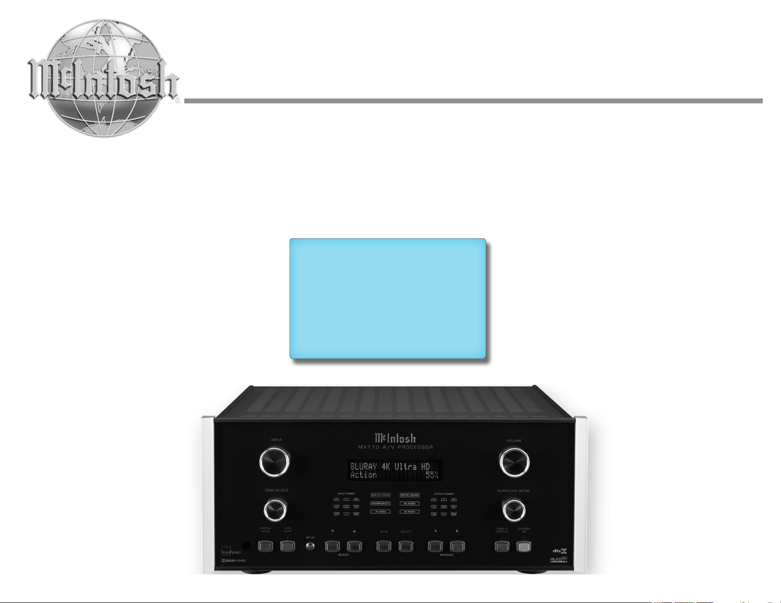
M X170
A/V Processor
Owner’s Manual
Page 2
Thank you from all of us at McIntosh
The MX170 A/V Processor marries a long tradition of
uncompromising quality with the latest home theater
technologies to bring you an unsurpassed luxury
entertainment experience.
The MX170’s superior multichannel reproduction
combined with RoomPerfect™ room correction
technology provides the backbone of your cutting edge
audio visual system.
Safety First
Please read all the enclosed MX170 SAFETY
INFORMATION included in separate documents.
You can never be too safe.
You have invested in a precision instrument that will
provide you with many years of enjoyment. Please take a
few moments to familiarize yourself with the features and
instructions to get the maximum performance from your
equipment.
If you need further technical assistance, please contact your
Dealer who may be more familiar with your particular setup
including other brands. You can also contact McIntosh with
additional questions or in the unlikely event of needing
service.
McIntosh Laboratory, Inc.
2 Chambers Street
Binghamton, New York 13903
Technical Assistance: (607) 723-3512
Customer Service: (607) 723-3515
Fax:(607) 724-0549
Email: support@mcintoshlabs.com
Website: mcintoshlabs.com
Make a Note
For future reference, you can jot down your serial number
and purchase information here. We can identify your
purchase from this information if the occasion should arise.
Serial Number:
Purchase Date:
Dealer Name
Copyright 2019 © by McIntosh Laboratory, Inc
2
Page 3

Table of Contents
Safety First ............................................................. 2
Thank you from all of us at McIntosh ................... 2
Make a Note ........................................................... 2
Trademark and License Information .....................4
What’s in the box ................................................... 5
Where to put it ....................................................... 5
Making the Cuts .................................................... 6
Securing the MX170 to a Shelf .............................. 6
Connections on the Back ....................................... 7
The Inputs ......................................................... 7
The Outputs ...................................................... 7
Making Connections ............................................. 8
HDMI ............................................................... 8
USB .................................................................. 8
SD Card Slot .....................................................8
10baseT L A N .................................................... 8
Microphone ....................................................... 8
RS232 ................................................................ 8
Wired IR Inputs ................................................ 8
Digital Inputs .................................................... 9
Analog Audio Inputs ......................................... 9
Phono Input ....................................................... 9
AC Power .......................................................... 9
Power Switch .................................................... 9
Balanced Audio Outputs ................................... 9
Power Control (Trigger) Outputs .................... 10
Digital Zone B Output .................................... 10
Net 2 Out ......................................................... 10
Data Out .......................................................... 10
The Front Panel ............................................ 11
Standby / On .................................................. 11
The Input Knob ............................................... 11
The Volume Knob ........................................... 11
The Arrow, Back and Select Buttons ............. 11
Trim Select Knob ............................................ 12
Surround Mode Knob ..................................... 12
Zone B ............................................................ 13
Display Mode .................................................. 13
LED Channel Status Indicators ..................... 13
Setup ............................................................... 13
Setup- The Installer Menu ................................... 13
Speaker Setup ................................................. 14
Speaker Types for Setup ................................. 15
Verify Speakers .............................................. 15
Adjust Subwoofer Level .................................. 15
RoomPerfect™ .............................................. 15
Channel Gain .................................................. 15
Audio Setup .................................................... 15
Audio Processing ............................................ 15
Voicing Setup .................................................. 16
Zone B............................................................. 16
Source ............................................................. 16
Video Setup .................................................... 17
Video Output .................................................. 17
Video Input ..................................................... 17
System Configuration .................................... 17
General Setup ................................................. 17
Trigger Setup .................................................. 18
Network Setup ................................................ 18
Manage Software ............................................ 18
Dolby-enabled speakers .................................. 19
Dolby Atmos and Auro-3D Setup Examples ....... 19
Bass Management Examples ............................... 20
Description of Remote Control Buttons .............. 21
Remote Control Batteries .................................... 22
RoomPerfect™ Setup ......................................... 22
Backup and Restore ............................................ 22
Factory Reset ....................................................... 23
Update Software .................................................. 23
Re-packing the MX170 ........................................ 24
Technical Specifications ..................................... 25
Voicing C u r ves .................................................... 26
List of Figures
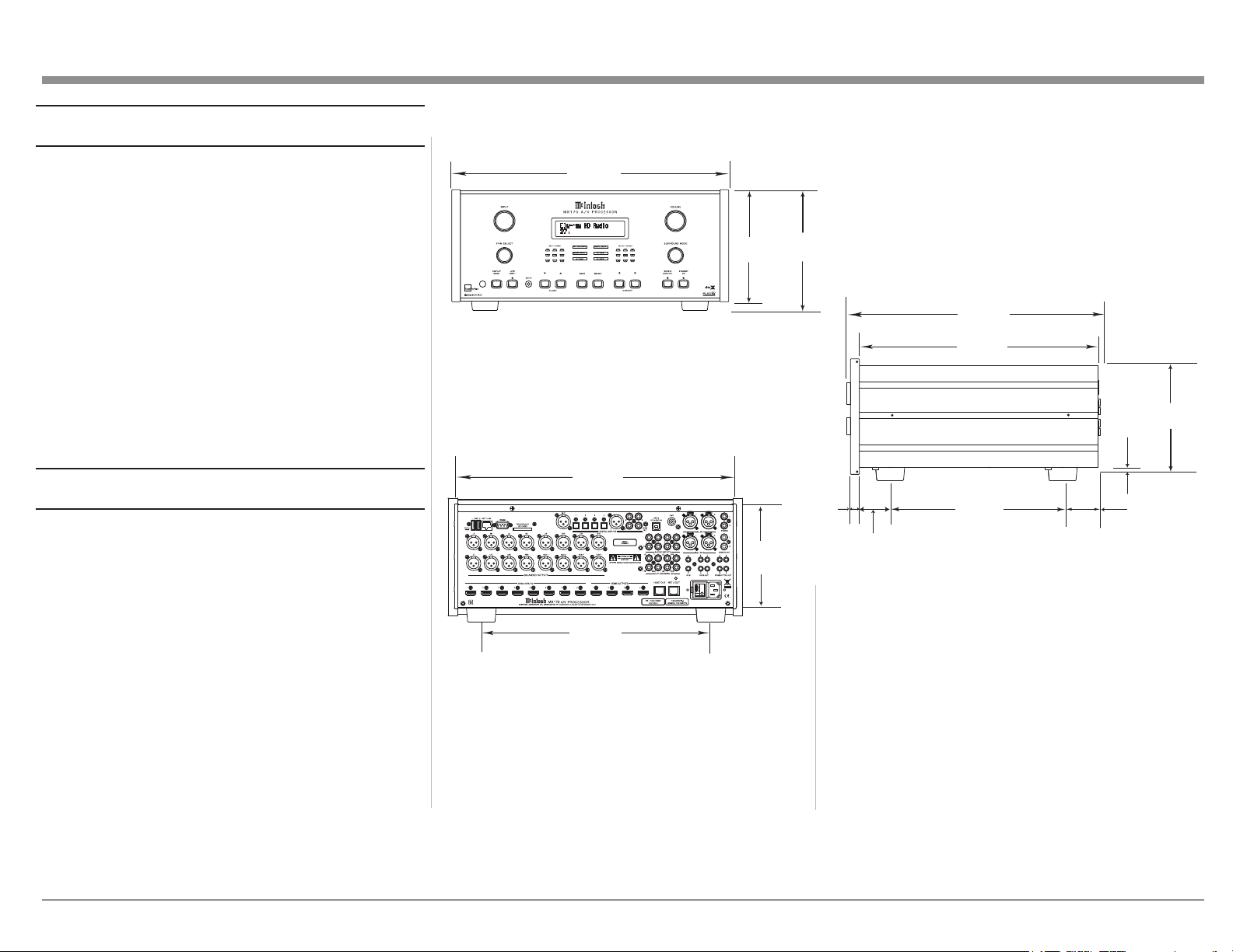
Figure 01– MX170 Dimensions ............................ 5
Figure 02– Custom cutout dimensions ................. 6
Figure 03– “L” bracket screws.............................. 6
Figure 04– MX170 Rear View ............................. 7
Figure 05– DB9 connector pin layout .................. 8
Figure 06– IR 3.5mm connector........................... 9
Figure 07– Power control (trigger) mini plug ..... 10
Figure 08– Data Out mini plug........................... 10
Figure 09– MX170 Front panel ........................ 11
Figure 10– Choosing SETUP from browser ...... 14
Figure 11– Speaker setup screen ........................ 14
Figure 12– Auro-3D example: 11.1 ..................... 19
Figure 13– Dolby Atmos Example: 7.1.4 ............ 19
Figure 14– 7.1.4 LFE Sub ................................... 20
Figure 15– 7.1.4 LFE Sub, Front XXL Speakers 20
Figure 16– 7.1.4 Front Subs ................................ 20
Figure 17– 7.1.4 Front Speakers, XL Surrounds . 20
Figure 18– RoomPerfect™ Focus Position ........ 22
3
Page 4
Trademark and License Information
The McIntosh MX170 incorporates copyright
protected technology that is protected by U.S. patents
and other intellectual property rights. The MX170
uses the following technologies:
This item incorporates copy protection technology
that is protected by U.S. patents and other intellectual
property rights of Rovi Corporation. Reverse engineering and disassembly are prohibited.
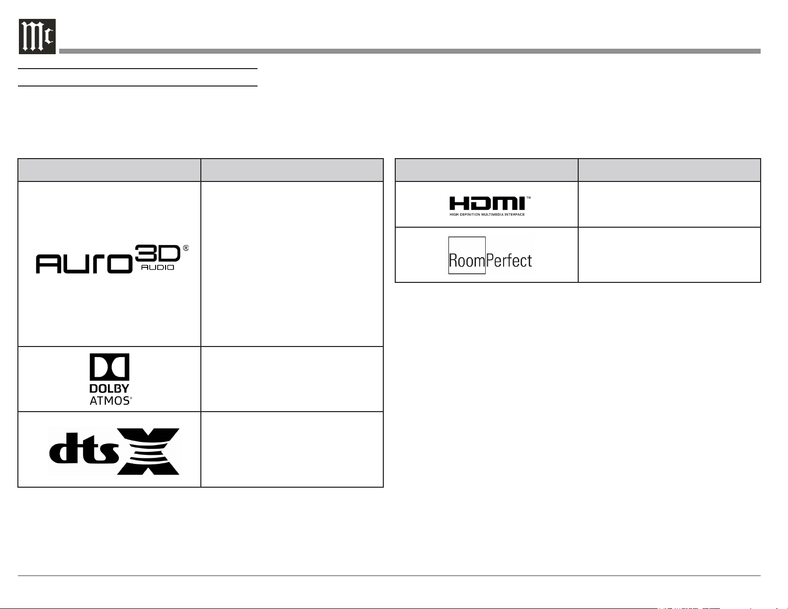
Trademark Logo License Information
Manufactured under license from Auro
Technologies. Auro-3D® and the related
symbols are registered trademarks of Auro
Technologies. All materials contained in this
work are protected by copyright law and may
not be reproduced, distributed, transmitted,
displayed, published or broadcast without the
prior written permission of Auro Technologies
NV or in case of third party materials, the
owner of that content. You may not alter or
remove any trademark, copyright or other
notice from copies of the content.
Auro Technologies: mail info@aurotechnologies.com, phone +32-(0)-14314343,
fax +32-(0)-14321224, www. aurotechnologies.com.
Manufactured under license from Dolby
Laboratories. Dolby, Dolby Atmos, Dolby
Surround, and the double-D symbol are
trademarks of Dolby Laboratories.
For DTS patents, see http://patents.dts.com.
Manufactured under license from DTS, Inc.
DTS, the Symbol, DTS in combination with
the Symbol, DTS:X, and the DTS:X logo are
registered trademarks or trademarks of DTS,
Inc. in the United States and/or other countries.
© DTS, Inc. All Rights Reserved.
Trademark Logo License Information
HDMI, the HDMI Logo and High-Definition
Multimedia Interface are trademarks or
registered trademarks of HDMI Licensing LLC
in the United States and other countries.
Manufactured under license from Lyngdorf
Audio A/S. RoomPerfect™ is a registered
trademark and the RoomPerfect™ logo is
a trademark of Lyngdorf Audio A/S. (C)
Lyngdorf Audio A/S 2009.
4
Page 5
What’s in the box
Front View of the MX170
Here is what is in the box besides all the shipping foam:
One MX170 A/V Processor
One accessory package including
• Microphone
• Microphone stand
• Microphone clip
• 25-foot XLR microphone cable
One hardware package
• Two “L” Mounting brackets (for securing unit
to shelf)
• Two screws #6 x 1/2 inch
• Four #6 washers
One manual package including this manual
One AC power cord
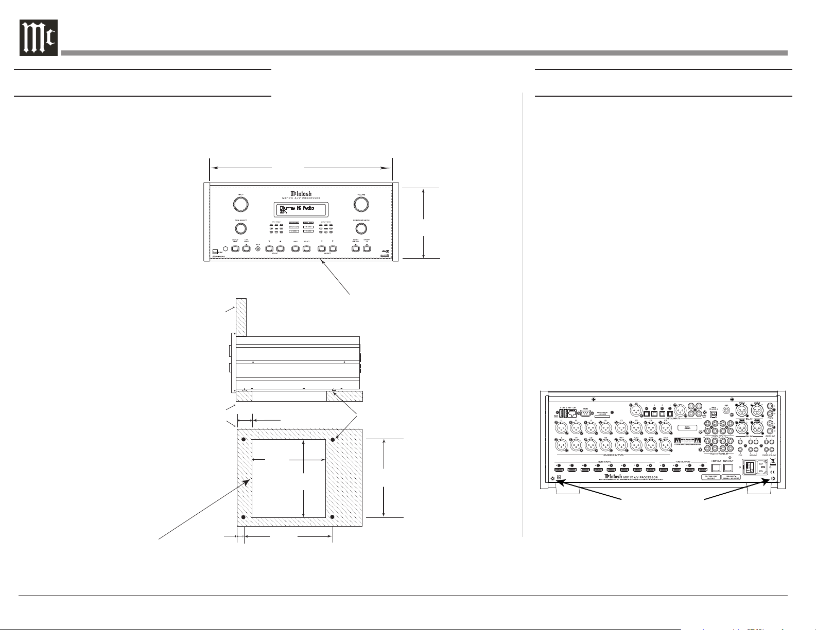
Where to put it
The MX170 A/V Processor can be placed upright on
a table or shelf, standing on its four feet. It also can be
custom installed in a piece of furniture or cabinet. The
four feet may be removed for custom installations.
If the feet are removed, the four feet together with
the mounting screws should be retained for possible
future use. Do not use different size screws when reinstalling the feet. With the feet removed, the MX170
requires a ventilation cutout. Dimensions for the panel
cutout and bottom ventilation cutout are shown in
Figure 02 on page 6.
Always provide adequate ventilation for your
MX170. Cool operation ensures the longest possible
operating life for any electronic instrument. Do not
install the MX170 directly above a heat generating
component such as a high-powered amplier. If all
the components are installed in a single cabinet, a
quiet running ventilation fan can be a denite asset in
17-1/2"
44.5cm
6-3/8"
16.2cm
7-5/8"
19.4cm
Rear View of the MX170
17-1/8"
43.5cm
13 -1/4"
33.7cm
7-1/8"
18.1cm
maintaining all the system components at the coolest
possible operating temperature.
A custom cabinet installation should provide the
following minimum spacing dimensions for cool
operation:
• 2 inches (5.1cm) above the top
• 2 inches (5.1cm) below the bottom
• 1 inch (2.5cm) on each side of the MX170 so
that airow is not obstructed
Side View of the MX170
16-1/2"
41.9cm
14-1/2"
36.8cm
3/16
0.5cm
13/16
2.1cm
"
1-15/16"
4.9cm
10-9/16"
26.8cm
Figure 01– MX170 Dimensions
2"
5.1cm
• 20 inches (50.8cm) depth behind the front panel
• 1-7/16 inch (3.7cm) in front of the mounting
panel for knob clearance
Be sure to cut out a ventilation hole in the mounting
shelf according to the dimensions in the drawing.
Figure 02 on page 6.
"
6-9/16"
16.7cm
5
Page 6
Making the Cuts
Securing the MX170 to a Shelf
Here are the dimensions for the cutouts needed for
custom installation. A ventilation opening is essential
for any installation with the four feet removed.
MX170 Front Panel
Custom Cabinet Cutout
Cabinet
Front
Panel
MX170 Side View
in Custom Cabinet
17-3/16"
43.66cm
Cutout Opening for Custom Mounting
6-
9/16"
16.67cm
A hardware package containing two “L” brackets and
two screws along with four washers can be used to
secure the MX170 A/V Processor to a shelf.
To secure the MX170 to a shelf using the supplied “L”
brackets:
• Remove the two screws in the lower corner on
the back of the MX170. See Figure 03.
• Attach the longer portion of the “L” bracket to
the rear of the MX170 using the same screw
just removed from the rear of the MX170 and
a supplied washer. Repeat for the other side.
Never use different size screws. The “L” bracket
should form a 90 degree angle with the lower
portion facing away from the rear of the unit
and resting on the shelf.
• Use the supplied screws and washers to attach
the lower portion of the “L” brackets to the
shelf.
MX170 Bottom View
in Custom Cabinet
Support
Shelf
9
-1/8"
23.18cm
Cutout
Opening
for
Ventilation
2-1/4"
5.72cm
Screws for attaching “L” brackets
Figure 03– “L” bracket screws
Note: Center the cutout Horizontally
on the unit. For purposes of
clarity, the above illustration
is not drawn to scale.
1-1/16"
2.70cm
12-5/16"
31.27cm
Figure 02– Custom cutout
dimensions
6
Page 7
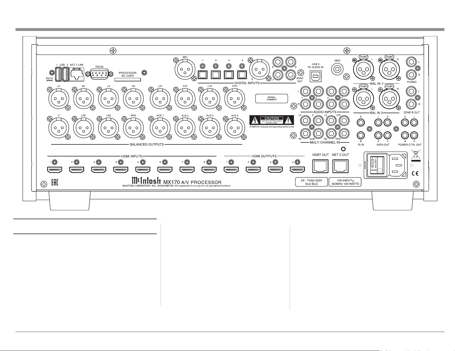
Figure 04– MX170 Rear View
Connecons on the Back
The MX170 A/V Processor has a wealth of
connections. They can be divided into Inputs and
Outputs.
The Inputs
Eight HDMI Inputs
Four optical Inputs
One balanced XLR (AES/EBU)
Three coaxial digital audio Inputs
Four analog RCA stereo pairs
Two analog XLR stereo pairs
One 8 multichannel RCA Inputs
One Moving Magnet RCA stereo pair
Two USB le/update Inputs
One USB streaming audio Input
One SD card slot (Stores Backup data)
One 10baseT LAN connector
One microphone Input for RoomPerfect™ setup
One RS232 connector
Two wired IR Inputs (one wireless IR on front)
One AC connector
The Outputs
16 balanced audio Outputs
One coaxial digital audio Output (for Zone B)
One Zone B RCA stereo pair
One HDbaseT Output
Four Power Control (trigger) Outputs
One Net 2 Out
Four Data Out
7
Page 8
Making Connecons
USB
RS232
HDMI
The MX170 A/V Processor has 8 HDMI Inputs. A
high-performance HDMI cable is recommended to
take advantage of the 18 Gbps speed capabilities
of all 8 HDMI Inputs. The HDMI cables should
support 4K@60Hz, HDR and YCbCr 4:2:2 (4:4:4/
RGB) as well as Ethernet and ARC. Cables designed
for HDMI 2.0 are ne. Though, HDMI is backward
compatible, older cables my have issues with the
higher bandwidth required for newer protocols.
When connecting to ARC enabled televisions,
Audio Return Channel (ARC) can provide two-way
communication between units allowing for power
control, volume control and lip-syncing functions
to ensure audio and video are perfectly matched.
This allows for more intelligent operation between
components as well as less cable clutter. Make sure
this feature is enabled in your TV’s setup menu.
HDMI Output 1 supports eARC. eARC allows for
even higher bandwidth and will allow for higher
quality audio including uncompressed 7.1 surround,
Dolby Atmos and DTS:X.
Though this manual divides HDMI jacks between
Inputs and Outputs, it should be noted that HDMI
communication is bidirectional. HDMI devices
perform a handshake to negotiate capabilities.
When connecting an eARC high-speed device,
HDMI Output 1 should be used for the connection.
HDMI Output 1 will receive information from the
connected device as well as transmit high-speed
data.
There are three USB Inputs. The two USB Type-A
Inputs are labeled USB 1 and 2. These two Inputs
are for data transfer and updating the MX170.
Voicings can be backed up and restored using either
of these ports.
The USB Type-B Input labeled USB 3 PC AUDIO
IN is used for USB audio connections from sources
such as a computer.
Do not use the USB ports for charging smartphones
and tablets.
SD Card Slot
Like the USB Inputs, the SD Card Slot can be used
for data transfer and back up and restore functions
of the MX170.
10baseT LAN
Use an ethernet cable to connect the MX170 to a
network router. This will allow setup and control of
the unit to be performed through a browser. Setup
is easier to navigate using a computer. To see the IP
address of a network connected MX170, push the
DISPLAY MODE button on the front of the unit
until the address is displayed. Putting this address
into a locally connected browser will allow control
of the unit remotely.
Microphone
Use the microphone Input for connecting the
supplied MX170 Microphone with the included
microphone (XLR) cable. This is used for the
RoomPerfect™ calibration for tuning the system
to your room. For instructions see “RoomPerfect™
Setup” on page 22.
The RS232 connection can be used for integration
into a home automation system.
The RS232 Input will accept a male DB9 connector.
Most installations require a null modem cable. The
port settings should be:
• 8 data bits, no parity and one stop bit
• Baud rate xed at 115,200 bits per second
For further information on using the RS232
control protocol or using RS232 over IP or HDMI,
you should request the document “MX170 A/V
Processor Serial Control Manual” from your dealer
or McIntosh Technical Assistance (see page 2).
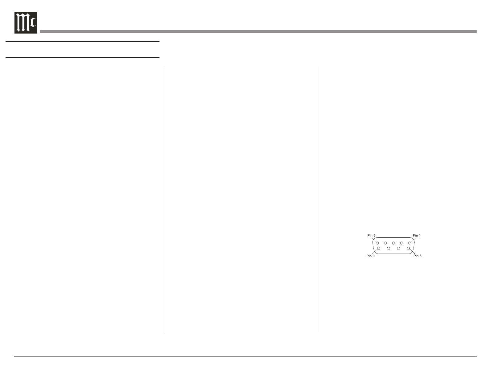
RS232 DB9 Connector Pin Layout:
1. N/C (no connection) 6. N/C
2. Data In (RXD) 7. N/C
3. Data Out (TXD) 8. N/C
4. N/C 9. N/C
5. Gnd.
See “Figure 05– DB9 connector pin layout”.
Figure 05– DB9 connector pin layout
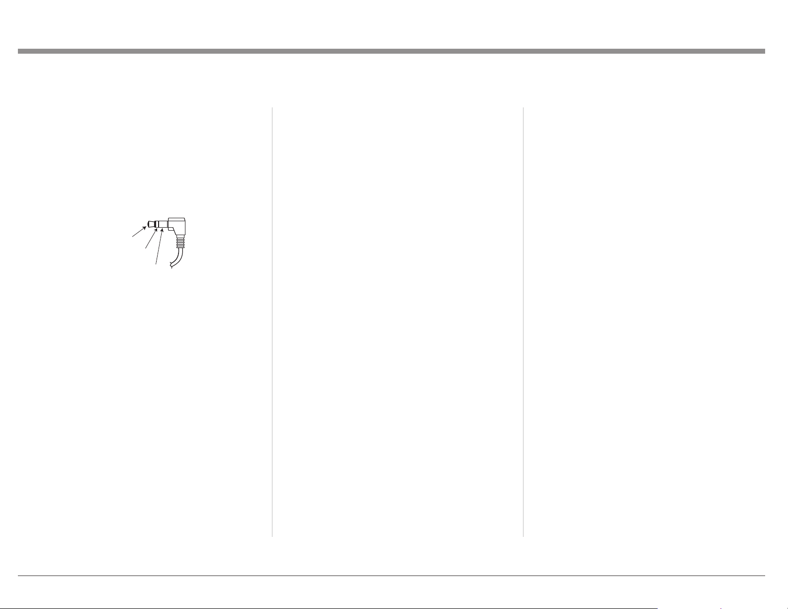
Wired IR Inputs
The IR Inputs allow two IR receivers to be attached
to the MX170. The Inputs are labeled “A” and
“B” and each can control their respective zones.
By attaching an IR receiver using a 3.5mm cable
(see “Figure 06– IR 3.5mm connector”), a Remote
Control can be used in another location without a
line-of-sight to the MX170’s front IR sensor. In this
8
Page 9
way, if Zone B is in another room, a Remote Control
can be used to adjust the MX170.
If using an external IR receiver for Zone A in the
same room as the MX170, you may wish to disable
the front IR sensor, which also controls Zone A,
to avoid timing issues of receiving the remotes
commands from two Inputs. The front IR can be
turned on/off in the Setup Menu:
SETUP>System conguration>General setup
(For explanation of menu path notation see the box
on page 14.)
IR Data
Control
N/C
Ground
Figure 06–
IR 3.5mm connector
Digital Inputs
There are 8 digital Inputs in the MX170
• 4 Optical
• 1 Balanced XLR (AES/EBU)
• 3 Coaxial
These Inputs are labeled 1 through 8 on the rear of
the MX170. A Digital Optical Audio Cable Toslink
Cable would be used for Inputs 1 through 4. Input
5 accepts a Balanced XLR (AES/EBU) cable and
Inputs 6 through 8 accept Digital Audio Coaxial
Cable which use a male RCA type connector.
These Inputs are named SPDIF 1 through 8. All
names can be customized in the setup program.
Unused Inputs can be deleted (and later restored).
Analog Audio Inputs
The MX170 can accept Input from seven analog
audio sources:
• There are four pairs of RCA jacks numbered 1
through 4 above the AUDIO Inputs title on the
rear of the MX170. The left male RCA jack of
a stereo pair should plug into the top jack and
the right male RCA jack should plug in below it.
In the SETUP menu and Input selection, these
Inputs are called “Analog 1 through 4.”
• There are two pairs of XLR balanced
connections labeled “BAL IN 1” and “BAL IN
2”. The left and right pairs are next to each other
and will accept male XLR cables. Looking at
the back, left is on the left and labeled “L”, the
other is labeled “R”.
• The eight RCA jacks above the title “MULTI
CHANNEL IN” accept eight channel audio
and are called “8 Channel Analog” in the Input
menu. The channels are:
• LF (Left Front)
• C (Center)
• RF (Right Front)
• LS (Left Surround)
• RS (Right Surround)
• LRS (Left Rear Surround)
• RRS (Right Rear Surround)
• LFE (Low Frequency Effects)
All the Input names can be customized in the
SETUP program, as well as deleted and restored.
Phono Input
A gold-plated stereo pair of RCA jacks and a goldplated ground post are for connecting a turntable
with a moving magnet cartridge to the precision
phono preamp section of the MX170. Turning the
ground post counterclockwise will loosen the post
and reveal a hole in the post for inserting the ground
wire. Turn clockwise to secure the ground wire.
AC Power
This connection is essential. Plug the female end of
the supplied AC Power Cord into the AC connector
located in the rear right corner of the MX170. Plug
the male end of the AC Power Cord into a grounded
and functioning AC outlet.
Power Switch
The Power Switch controls the overall power to the
MX170. With the switch in the “0” position, the
standby button, or the Remote Control power button
will not turn the unit on. With the Power Switch
in the “|” position, the MX170 is in standby mode
and can be powered on and off via the front standby
switch and Remote Control.
Balanced Audio Outputs
There are 16 male balanced XLR connections on the
back of the MX170 to accommodate a wide variety
of speaker congurations. Connect balanced XLR
cables to the corresponding powered speakers or
ampliers. Here are the possible connections:
LF (Left Front)
RF (Right Front)
LS (Left Surround)
RS (Right Surround)
LTF (Left Top Front)
RTF (Right Top Front)
LTR (Left Top Rear)
RTR (Right Top Rear)
C (Center)
LFE (Low Frequency Effects)
LRS (Left Rear Surround)
RRS (Right Rear Surround)
AUX1
9
Page 10

AUX2
AUX3
AUX4
This is all easier said than done. Setting up speakers
for a surround system takes planning, measuring and
installation. Depending on your level of expertise
and available time, you may wish to employ the
services of your McIntosh Dealer for expert setup of
your system. Professional installation of in-ceiling
speakers is particularly important due to gravity and
the location above your head.
The number, types and locations of speakers are
key elements in setting up the system. There are
a multitude of possible congurations, and the
MX170 is very exible in its setup to adapt to many
congurations.
Often surround setups are referred to by numbers
for example 7.1.4 or 9.1.2. The rst number refers to
the number of traditional surround speakers (front,
center and surround). The second number is the
number of subwoofers that can be connected, and
the third number refers to the number of in-ceiling
or upward ring speakers in the setup.
The type of speaker (size and location) will be
entered later during Speaker setup. The distance
of the speaker from the listening location will be
entered in the RoomPerfect™ setup. Make note of
this information.
At this stage, the connection from the MX170 to the
various ampliers and powered speakers should be
made using quality balanced XLR cables.
Power Control (Trigger) Outputs
The MX170 has four power control Outputs, one for
Zone A and one for Zone B, and two that allow for
custom setup. Power Control enables power on/off
signals to go to connected components so that other
components can automatically power on (or off) as
called for by the MX170. For example, you may
want a DVD player and certain monitor to power on
when HDMI 1 Input is selected, or you may want
all components to power off when powering off the
MX170.
Connect components using a 3.5mm stereo mini
plug. See Figure 07 below.
Power
Control
Meter
Illumination
Control
Figure 07– Power control (trigger) mini
Ground
plug
For components that will power on when Zone A
is active, use Power “A” and for Zone B use Power
“B”. For custom settings, connect to Power “1” and
Power “2” which will be congured in the Setup
program later on.
Digital Zone B Output
This coaxial digital audio Output provides a xed
level Output from the selected Zone B source. Use a
digital coaxial cable with a male RCA connector.
Net 2 Out
This port allows an additional network connected
component to be connected without needing an
additional router port. Use an ethernet cable to
connect the component to the Net 2 Out port.
This port functions when the MX170 is on or
in “Network” Standby mode. In “Deep sleep”
standby mode, the Net 2 Port will not function.
Standby options are controlled in SETUP>System
conguration>General setup> under the Power
management section. (For explanation of menu path
notation see the box on page 14.)
Data Out
The MX170 will convert IR Remote Control data
to share with McIntosh components connected to
the Data Ports. This allows units out of range of an
IR signal to receive commands. There are four Data
Ports. Each port can be assigned to different Inputs
so that only the components involved with the Input
will receive data. For instance, HDMI 1 can be
assigned to DATA OUT 1 and a connected McIntosh
DVD player can be controlled when the HDMI
Input is selected. A unit connected to a different
Data Port would not receive the commands.
To assign a Data Port to an Input, go to
SETUP>Source>[choose source]>Data out>[select
data out #.
To connect a McIntosh unit to a Data Port, use a
3.5mm stereo mini phone plug cable. See Figure 08.
Data
Signal
N/C
Data
Ground
Figure 08– Data Out mini plug
10
Page 11

Figure 09– MX170 Fro nt pan el
The Front Panel
The iconic front glass panel of the MX170 provides
knobs and buttons to control the unit as well as an
informational display and LED status lights that
display the current mode.
Standby / On
The red STANDBY / ON button toggles the MX170
between on and standby mode. The STANDBY
button will only work if the rear Power Switch
(page 9) is on. When the unit is in standby
mode, it can also be toggled on/off using the
Remote Control or the browser interface. To use the
on/off button in the top right corner of the browser
interface, the MX170’s power management must
be set to “Network” as opposed to “Deep sleep.”
When the power management is set to Deep Sleep,
the MX170 can not be woken up from the network
interface. The Power management can be setup
under SETUP>System conguration>General
setup>Power management. (For explanation of
menu path notation see the box on page 14.)
The Input Knob
The Input Knob can be turned clockwise or
counterclockwise to scroll through all the Inputs
that are enabled in Setup. All Inputs are available by
default.
The Volume Knob
Turn this knob clockwise to raise the volume and
go the other way to make it quieter. A maximum
volume of 59% is the factory default, but this can
be set to any value between 12% and 99% in Setup.
A maximum volume prevents the MX170 from
accidently sending higher signals than your situation
permits. See “General Setup” on page 17.
The Arrow, Back and Select
Buons
These buttons are used to navigate menu screens
and selections in the Trim menus. The arrows allow
scrolling up , down , left , and right , when
those are menu choices. The SELECT button
accepts an option and the BACK button returns to
11
Page 12

the previous menu.
Trim Select Knob
Now that you are familiar with the arrow, Back and
Select buttons, you can change many settings using
the Trim Select Knob. Turn the Trim Knob to access
any of the following:
• Voicing- There are seven built-in equalization
settings. Use the up and down buttons to
scroll through the choices. You can push
SELECT to choose and return to the previous
screen or wait a few seconds and this will
happen automatically. The built-in equalization
settings are: Neutral (at), Music, Music II,
Relaxed, Tilt, Action, and Action+Movie. You
can edit existing voicings and add new ones in
SETUP. Go to SETUP>Audio setup>Voicing
setup and choose a voicing to edit or choose
“Add” and create a new voicing with up to eight
lters.
• Bass- Use the up and down buttons to
adjust the bass level between -12dB and +12dB
in 0.5dB increments. The right and left
buttons set the upper adjustment limit between
20Hz and 800Hz in 10Hz increments. The
adjustment is saved for an individual Input.
• Treble- Use the up/down buttons to adjust
the treble level between -12dB and +12dB in
0.5dB increments. The right/left buttons
set the lower adjustment limit between 1,500Hz
and 16,000Hz in 500Hz increments. The
adjustment is saved for an individual Input.
• VFD Level- Use the up/down buttons to set
the brightness level of the VFD (Vacuum
Fluorescent Display). The default for the
information display is 100% which can be
changed to 25%, 50% or 75%.
• Lip Sync- This trim adjustment allows the
timing of the audio to be adjusted for
synchronization to video. Use the up/down
arrows for 5ms increments and the right/left
buttons for 25ms increments up to a total of
500ms.
• AMP Light- This allows for the meter lights, of
a McIntosh amplier connected with a power
control cable, to be toggled on and off using the
up and down buttons.
• Trim Center- This trim adjustment allows for
the adjustment of the Center Channel volume
level relative to the Front and Surround
Channels. Use the up/down buttons to
adjust from -10dB to + 10dB in 1dB increments.
• Trim Center- This trim adjustment allows for
the adjustment of the Center Channel volume
level relative to the Front and Surround
Channels. Use the up/down buttons to
adjust from -10dB to + 10dB in 1dB increments.
Any adjustment will be lost when the Input is
changed.
• Trim Surrounds- This trim adjustment allows
for the adjustment of the Surround Channels
volume level relative to the Front, Center and
LFE Channels. Use the up/down buttons to
adjust from -10dB to + 10dB in 1dB increments.
• RoomPerfect™ - The RoomPerfect™ room
correction process (“RoomPerfect™ Setup” on
page 22) can generate correction settings for
up to four Focus positions as well as a more
general Global setting. This trim setting allows
quick access to change between various saved
settings or to Bypass RoomPerfect™
altogether. Use the up/down buttons to
scroll through all saved settings.
Surround Mode Knob
The MX170 provides eleven different default
Surround Modes. These modes include upmixing
options such as DTS NEO X which will create up to
11.1 channel surround from sources like 5.1 and 7.1
surround signals or even from stereo signals. Dolby
restricts the upmixing of Dolby signals to Dolby
upmixer. Non-Dolby upmixer choices will have no
effect on a Dolby source. Therefore, Dolby upmixer
should be selected for all Dolby upmixing, and will
work on non-Dolby signals as well. The MX170
Surround Processing Modes are:
• None
• Dolby Upmixer
• Neural:X
• Auro-3D/Auromatic
• Auro-2D
• Auro-Stereo
• Auro-Native (as recorded)
• Virtual-X
• Legacy (see below)
• Stereo (This will downmix the signal)
• Party
The Legacy Mode will pass older non-Auro, nonDTS:X, non-Atmos formats with no height or
object oriented content without upmixing. This
content may include Dolby TrueHD, Dolby Digital,
Multichannel PCM, DTS Master Audio, as well as
stereo and surround formats up to 7.1.
Below are speaker congurations for Auro-3D and
Dolby Atmos. If Dolby Atmos material is played
in an Auro-3D setup, the system will try to match
the Auro-3D specic speakers to the nearest Dolby
Atmos equivalent; the same goes for playing Auro3D material on a Dolby Atmos setup. The system
will also handle hybrid setups with both types of
12
Page 13

speakers.
Auro-3D:
• HL (Height Left)
• HC (Height Center)
• HR (Height Right)
• HLS (Height Left Surround)
• HRS (Height Right Surround)
• TOP (Top ceiling, AKA VoG / Voice of God)
Dolby Atmos:
• LTF (Left Top Front)
• RTF (Right Top Front)
• LTM (Left Top Middle)
• RTM (Right Top Middle)
• LTR (Left Top Rear)
• RTR (Right Top Rear)
• LW (Left Wide)
• RW (Right Wide)
For examples, see “Dolby Atmos and Auro-3D
Setup Examples” on page 19.
DTS:X boasts the exibility to support any standard
surround setup as well as congurations up to an
11.2 channel system.
Zone B
The ZONE B CONTROL button allows the front
panel to be used to control the power, Input and
volume for components connected to the Zone B
Output of the MX170. Zone B can be set to any
Input or can be set to follow whatever Input is
chosen for the Main Zone. In the Zone B mode,
the red LED above the ZONE B button will
illuminate. If Zone B is off, turn it on by pushing the
STANDBY ON button which will also have a red
light lit above it. To exit Zone B control, push the
Zone B button again.
If ZONE A is powered off while Zone B is still on,
re-powering Zone A will automatically mute Zone
B.
Display Mode
The front panel will show the current Input, voicing
setting and volume level by default. Using the
DISPLAY MODE button, additional information
can be accessed. Pushing the DISPLAY MODE
button will toggle through the following additional
screens:
1. Format of incoming audio signal
2. Processing status of the Audio Out signal
3. Incoming and outgoing resolution of the
current video signal
4. The current IP address of the MX170
The default screen will return after a few seconds.
LED Channel Status Indicators
The yellow LEDs in the center of the MX170 front
panel provide a visual display of the status of the
Main Zone’s signal.
The left side illuminates which channels are present
in the Input format of the signal.
The middle section shows the following
information:
• ANALOG SIGNAL
• DIGITAL SIGNAL
• RoomPerfect™
• HD AUDIO
• 4K VIDEO
• 3D AUDIO
The right side shows the channels of the audio
Output.
Here are the channel abbreviations used on both the
left side (Input FORMAT) and right side (Output
FORMAT) indicators:
• LF- Left Front
• C- Center
• RF- Right Front
• LS- Left Surround
• LFE- Low Frequency Effects
• SUB- Subwoofer
• RS- Right Surround
• LRS- Left Rear Surround
• S- Surround (RS + LS)
• BS- Back Surround (RS + LS)
• RRS- Right Rear Surround
Setup
Pushing the SETUP button will bring up the
Installer menu on an attached monitor. When in
setup mode the Display will read “Installer Menu”.
To exit setup mode, push the SETUP button again.
Setup- The Installer Menu
The factory default settings will allow you to use
the MX170 as soon as you properly connect your
components. But the setup program is quite robust and
allows for great customization and optimization.
MX170 setup can be performed by using either the
setup button on the front panel and using an attached
monitor or through a web browser on a computer if
the MX170 is connected to your network. Chrome or
Firefox browsers are recommended. Other browsers
may not function correctly.
The procedures and screens are essentially the same
using either method. You may nd the use of a mouse
and a keyboard available in the browser method easier
to navigate than using the arrow buttons on
the front panel or Remote Control for entering
information.
We will be using the browser setup method here, but
13
Page 14

the underlying logic and procedures are the same.
To bring up the interface on your browser, put the IP
address of the MX170 in the address bar. To determine
the IP address, push the DISPLAY MODE button until
the IP address appears in the display.
Choose SETUP from the top left of the screen. The
local version will start in the SETUP menu. (See
Figure 10.)
Figure 10– Choosing SETUP from browser
Setup has the following sub-menus:
• Source
• Speakers & room
• Video setup
• Audio setup
• Zone B
• System conguration
• Manage software
In this manual, sub menus are denoted in the style
“SETUP>Video setup>Video Input” which means
from the “SETUP” menu choose “Video setup”
and then choose “Video Input”.
Speaker Setup
SETUP>Speakers & room>Speaker setup
This is where to tell the MX170 the numbers and
14
Figure 11– Speaker setup screen
types of speakers in your system. When entering
this menu, you will need to acknowledge that “any
changes to the speaker setup will require rerunning
your RoomPerfect™ measurements.” Choose
“Proceed” to continue.
Select a speaker location starting with the LF (or
RF- they will be the same). Choose the speaker size
according to this guide:
Speaker size:
• NONE- This means the Output is not used
• XXL- Plays a full range signal and can accept
bass re-directed from other channels when in
the LF/RF, LS/RS and LRS/RRS positions
• XL- Full range but bass will not be re-directed
to these speakers
• L- Bass cutoff frequency is 40Hz
• M- Bass cutoff frequency is 80Hz
• S- Bass cutoff frequency is 100Hz
• XS- Bass cutoff frequency is 120Hz
• Custom- Bass cutoff can be manually set
When choosing a custom cutoff frequency, select a
frequency higher than the lowest frequency that
your speaker can play. If redirected bass will be
played by a subwoofer instead of the full range
speaker, choose a cutoff lower than the highest
frequency the subwoofer can play.
The Bass cutoff frequency option is only available
for the Custom speaker choice. Choose a bass cutoff
frequency for custom speaker setting.
Page 15

Enabling Natural roll-off (choosing “Yes”) will
send the full range signal to the speaker as well as
sending the bass frequency based on the cutoff to a
subwoofer or XXL speaker.
Enabling bi-amping (choosing “Yes”) will send an
exact copy of the existing signal to a pair of AUX
Outputs. This option is only available for the LF/RF
speakers.
Add each speaker you have by selecting the + by
appropriate description and lling in the data. The
speaker will be assigned to an Output.
Speaker Types for Setup
Position Description
L Left
C Center
R Right
Sub L Subwoofer Left
LW Left Wide
RW Right Wide
SUB R Subwooofer Right
SUB LFE Subwoofer Low
Frequency Effects
HL Height Left
HC Height Center
HR Height Right
LTF Left Top Front
RTF Right Top Front
HLS Height Left Surround
LTM Left Top Middle
TOP Top Ceiling/Voice of
God
RTM Right Top Middle
Position Description
HRS Height Right Surround
LS Left Surround
LTR Left Top Rear
RTR Right Top Rear
HLR Height Left Rear
HRR Height Right Rear
SUB LR Subwoofer Left Rear
LRS Left Rear Surround
CB Center Back
RRS Right Rear Surround
SUB RR
Subwoofer Right Rear
Verify Speakers
SETUP>Speakers & room>Verify speakers
Select “Verify speakers” to step through each
connected speaker. Sound should be heard from
the current speaker. Select “Next” or “Previous” to
cycle through available speakers.
Adjust Subwoofer Level
SETUP>Speakers & room>Adjust Sub
The Adjust Sub menu is a tool for setting the level
for an attached subwoofer. It will compare the
level of the Front Left speaker and the subwoofer.
It will then suggest changes to make on the level
adjustment for a powered sub.
To use this tool, attach the included microphone and
cable to the MIC jack in the rear of the MX170 and
position the microphone in the primary listening
location. Select start and follow the prompts.
It is advisable to perform the sub adjustments prior
to using RoomPerfect™ . RoomPerfect™ will
perform ne tuning of your system, but it is better to
manually set your preferred overall subwoofer level
as opposed to using equalization to accomplish this.
RoomPerfect™
RoomPerfect™ is an advanced calibration and
adjustment system that will get the most out of your
system. For setup instruction see “RoomPerfect™
Setup” on page 22.
Channel Gain
SETUP>Speakers & room>Channel gain
Channel gain allows for full range (20Hz-20kHz)
adjustments of gain by channel. Changes can be
made for each saved RoomPerfect™ setting
including Global and Bypass.
• Choose “Edit” to make changes
• Choose the RoomPerfect™ settings you wish
to adjust
• Settings can be changed for Dolby Atmos/
DTS and for Auro signals
• Choose “Save” to keep the new settings or
cancel to lose your changes
If you wish to make gain adjustments that are not
full range (so as to not effect a sub playing that
channel for instance), use Speaker Setup (page
14) instead.
Audio Setup
The Audio setup menu consists of two sub menus:
Audio Processing and Voicing setup.
Audio Processing
SETUP>Audio setup>Audio processing
This menu allows for management of the audio
processing presets for DTS, AURO and Dolby.
15
Page 16

For DTS, center gain adjustments can be set for the
three available DTS presets (Neo:X music, Neo:X
game and Neo:X cinema). Dynamic range control,
also known as Night Mode, can be enabled and
percentage of control set. Night Mode raises the
volume of quiet sounds and lowers the volume of
loud sounds. Enabling Phantom Center allows a
center channel to be generated from left and right
stereo signals. Enabling channel remapping will
allow for remixing of the soundtrack to compensate
for a different channel layout from the original mix.
Enabling Fade In will allow the volume to come up
to level gradually when the Input is chosen.
For Dolby, enabling Center Spread will spread
the center channel dialogue into the left and right
speakers to accommodate very large screens. There
are two different Dolby dynamic range controls
(Night Modes), one for TrueHD and one for Atmos.
Each can be enabled separately for program material
of that type. Auto for TrueHD will follow the
instructions of the TrueHD source.
For AURO, the “Set AURO strength” changes the
level of upmixed channels relative to the original
Input signal. AURO presets have settings optimized
for different audio material:
small pop/chamber music and movies with a
lot of dialog such as comedies
medium1 jazz and typical movies and TV shows
medium2 orchestral/ larger spaces and action
movies with big explosions
speech Primarily dialog with little spatial
information such as news
Voicing Setup
SETUP>Audio setup>Voicing setup
A Voicing is an equalizer lter that can be activated
to amplify or attenuate certain frequencies according
to your personal preferences. This equalization
is an addition to the RoomPerfect™ corrections.
Voicing setup allows you to edit, delete, add, or load
voicings.
In the web interface (recommended), you can edit
or add a voicing by combining up to eight lter
sections. For each section, you can choose between
parametric or high and low shelves as well as high
and low-pass lters. Once the lter type is selected,
you can insert a center frequency, Q (bandwidth),
and gain. Then the lter, including the nal voicing,
is shown as a graph so that you can immediately see
the result.
Voicing can be accessed through the Trim Select
Knob (page 12).
Zone B
SETUP>Zone B
Use this menu to set default values for Zone B. A
maximum volume can be set. A xed volume can
also be set. The xed volume can not exceed the
maximum volume setting. Default power setting
can be off, follow Main, or independent. If set as
independent, Zone B will remain on if on when the
Main Zone is powered off.
Source
SETUP>Source
The Source menu allows you to add, delete, edit and
arrange sources.
To add a source, select the “Add source” button in
the top right corner of the menu. This will bring
up options for the source. You will see these same
options when selecting to edit an existing source.
The options are:
• Source name: this will be the name that will
display for this channel. Customize at will.
• Lipsync offset: values between 0ms and
500ms can be set as a lipsync delay to match
audio and video playback.
• Volume offset: values between -20dB and
+20dB can be set to compensate for different
Input levels from different sources.
• Audio Input: select from a list of available
sources to assign to this Input. If you want the
audio Input to match the video Input from an
HDMI source, select HDMI Audio.
• Postprocessing: set the default postprocessing
mode from a list. Choose “none” for no
processing or “no change” to not alter the
current processor when this Input is chosen.
• Default voicing: select the default voicing for
this Input from a list. Choose “no change”
to keep current voicing when this Input is
chosen.
• Video Input: choose from a list of available
HDMI sources or none to assign to this Input.
• Data out: you can assign any one of the
four Data Out ports to send control data
to connected components when this Input
is chosen. See “Figure 11– Speaker setup
screen” on page 14.
• IR command: you may choose an available
component name from a list to assign the
source to an Input name that could be used
for controlling the unit by a control system.
For example, if HDMI 2 was assigned to
“DVR”, then a control device sending the
DVR command would select HDMI 2 on the
MX170.
• Trigger out: A trigger can be assigned to the
Input. Available triggers are controlled in the
trigger setup menu. A trigger not assigned to
16
Page 17

a source (Source, Source A or Source B) will
not appear as an option. (See “Trigger Setup”
on page 18.)
Select Save to keep changes.
Video Setup
The Video setup menu has two sub menus: Video
Output and Video Input.
Video Output
SETUP>Video setup>Video ouput
This menu manages the default and preferred setting
for all video Outputs. In most cases the factory
default settings are recommended.
Choose an Output to be the MX170’s main video
Output. Other Outputs can be congured to “Follow
main”.
For each HDMI Output and the HDBT OUT, the
following settings can be changed:
Preferred resolution: The default of none will
allow the MX170 to negotiate the best resolution
supported by the video display. Specic resolutions
can be specied, but the MX170 does not scale the
resolution and will pass the source’s resolution.
Default video source: the Output can be set to
follow the main video Output or set to any of the
eight HDMI Inputs. Choose “Independent” if the
Output will be controlled externally such as from an
RS232 connection.
HDMI Audio out: The default setting is
Passthrough which will send the audio from the
source. Audio can also be changed to Off or Zone B
audio can be selected for second zone applications.
USB or HDMI Inputs will not work for Zone B
HDMI.
The HDBT (HDBaseT) connection allows there
to be very long cable runs between the MX170
and a monitor. CAT6 or greater cable with RJ45
connector can be used for distances up to 328 feet
(100m). Settings work the same as the other four
HDMI Outputs.
Video Input
SETUP>Video setup>Video Input
In this menu, each of the eight HDMI Inputs can
be customized as to what information is advertised
to the sources. The HDMI Inputs send EDID
(Extended Display Identication Data) to the source
to negotiate acceptable formats.
In the Video setting section, the following options
are available for the various resolutions:
• Always - always advertise support for the
given resolution, regardless the supported
Outputs of any connected TV
• Never - never advertise support for the given
resolution, regardless of what the supported
resolutions of any connected TVs are
• One - advertise support for the given
resolution, if one of the TVs on the Outputs
support the resolution
• All - advertise support for the given
resolution, if all the TVs on the Outputs
support the resolution
If All is selected for HDR and one of the TVs is not
HDR compliant, then HDR functionality may be
disabled for all. Select One or Always in this case.
With Always, a non-HDR TV may not like the HDR
signal.
For the Audio setting, any selection other than
“PCM, bitstream, multichannel” will require the
source to do the decoding. Choices for audio
advertised to the source are:
• PCM only, multichannel (default)
• PCM stereo only
• PCM stereo up to 48kHz only
The HDCP (High-bandwidth Digital Content
Protection) compatibility should generally be left
as the default setting HDCP 2.2 unless you are
experiencing difculties with this setting. If there
are sources that have difculties with this, you can
select from these other settings:
• HDCP 1.4 – only advertise HDCP 1.4 support
• No DDC – there will be no communication
on the DDC (Display Data Channel), so the
source cannot read the EDID. This will also
disable HDCP handshakes (units will not
exchange authorization info)
• Sink – the MX170 will look like a TV to
the source. As some sources have very
bad repeater support, they do not function
properly with a processor like the MX170,
and this setting will bring the source to Output
a picture
Select Save to keep changes.
System Conguraon
The System Conguration menu has three sub
menus: General setup, Trigger setup and Network
setup.
General Setup
SETUP>System configuration>General setup
Power management has two modes:
• Network- this allows the MX170 to be turned
on through the network interface or a control
system
• Deep sleep- this prevents remote powering of
the MX170
17
Page 18

Enter the number of minutes of inactivity before the
MX170 enters the chosen standby mode. Enter “0”
to disable the standby feature.
Default volume settings allow a maximum volume
to be set above which the MX170 can not be set.
You also can set whether the MX170 starts up with
the last volume played or set a value for the unit to
start up with each time.
Show bypass will show or hide the choice of
bypassing RoomPerfect™ settings in the trim menu
under RoomPerfect™ . Select “Yes” to make the
bypass choice available or “No” to remove the menu
option.
Display timeout sets a number of seconds for the
display to dim after changing a setting or Input. To
disable the dimming of the display choose “0”.
Password allows password protection of the
web interface menu. This prevents accidental or
unauthorized changes being made to the MX170
through the web interface. The interface is still
available to control the Main Zone and Zone B.
To password protect the setup menu, select “Yes”
and then place the MX170 in standby. The next time
it is powered on, the setup menu will be protected.
To enter the setup menu when password protected,
the IP address must be followed by “/setup” (for
example 192.168.1.127/setup). When prompted for a
password enter “7800.”
Enable front IR sensor allows you to turn the front
IR sensor of the unit on and off. This may be helpful
if the IR codes of another unit are conicting with
the MX170.
HDMI CEC settings
Consumer Electronics Control (CEC) is a feature
of HDMI that theoretically allows users to control
multiple connected devices through one Remote
Control. This can work ne in some cases when you
want to turn on the television and also power on
other related devices, but there may be times when
you do not want this or other connected events to
happen. You can Disable HDMI CEC if desired.
With CEC enabled you can choose to Enable SAC
to allow the volume control of the TV to control the
audio volume.
If you plan on using ARC (Audio Return
Channel), CEC must be enabled and the Audio
Input of an HDMI channel should be set to Audio
Return Channel. (SETUP>Source>HDMI x> Edit>
Audio Input.)
OSD info level gives three options for the amount of
information shown on attached displays:
• Show all will display change of Input and
change of volume
• Show volume will display the volume level
when changed
• Show nothing will do just that
Trigger Setup
SETUP>System configuration>Trigger setup
Trigger setup allows you to control what devices
control other components power status. Zone A and
Zone B trigger Outputs are tied to their respective
zones, but Trigger 1 and Trigger 2 can be congured
as follows:
• Off – No action
• Source – When the preset source for any
zone is selected, it will trigger. Use source
setup menu to associate with a source. (See
“Source” on page 16)
• Source A – When the preset source for Zone
A/Main Zone is selected, it will trigger
• Source B - When the preset source for Zone B
is selected, it will trigger
• Power A – When Zone A/Main Zone is On, it
will trigger
• Power B - When Zone B is On, it will trigger
• Power any - When any Zone is On, it will
trigger
Network Setup
SETUP>System configuration>Network setup
Network setup has a Manual and Auto setting. The
Auto setting is simplest in that the MX170 will be
assigned an IP address from your router and all the
pertinent information will automatically be lled. If
you are familiar with networks, you may prefer to
assign an IP address. The advantage to this is that
you will have a xed unchanging IP address of your
choosing.
Choosing Manual setup will allow you to edit the IP
Address, Subnet mask, Gateway and DNS elds.
The assigned IP address of the MX170 can be
found by pushing the DISPLAY MODE button (see
“Display Mode” on page 13).
Select Save to keep any changes.
Manage Soware
The Manage software menu has two sections:
• Information
• Backup & Restore
The Information Menu has three sub-menus:
SETUP>Manage software>Software
information
Software information- Here you will nd version
numbers for various software used in the MX170.
This is helpful in some troubleshooting situations.
SETUP>Manage software>Network information
Network information- This menu provides a
summary of various network addresses.
SETUP>Manage software>Download system log
18
Page 19

Download system log- This menu allows you to download the MX170’s system
log which provides detailed information about the performance of the MX170.
This can be helpful to service personnel in case of difculties. Simply select
“Download system log” for a copy of the log.
For information on the Backup & Restore sub-menu see “Backup and
Restore” on page 22.
This sub-menu includes Backup, Restore, Factory Reset and Update software.
Dolby Atmos and Auro-3D Setup Examples
The system supports Dolby Atmos as well as Auro-3D. If Dolby Atmos material
is played in an Auro-3D setup, the system will try to match the Auro-3D specic
speakers to the nearest Dolby Atmos equivalent; the same goes for playing Auro-3D
material on a Dolby Atmos setup. The system will also handle hybrid setups with
both types of speakers.
DTS will work with a variety of setups including the Auro 3D setup below without
using the TOP speaker.
Dolby-enabled speakers
For Dolby Atmos setups, it is possible to add Dolby Enabled Speakers instead of
using top speakers mounted in the ceiling.
Dolby Enabled Speakers are extra speakers placed on top of or built into the
speakers on the main positions in the system (front, surround and rear surround).
These extra speakers re sound upwards toward the ceiling. The sound is then
reected to give the listener the sound from above without having actual top
speakers installed.
To add Dolby Enabled Speakers to your system, select the speakers which the
Dolby Enabled Speakers are associated with. For instance, if you have Dolby
Enabled Speakers on top of your front and surround speakers, go to the settings
for these speakers and activate the Dolby Enabled Speaker option. This will then
give you the option to select the size of the Dolby Enabled Speaker. Once this is
done, the system will nd out which signal is to be routed for this speaker and
will add an Output for it.
Notice that playback of Auro-3D material will not make use of Dolby Enabled
Speakers.
Figure 12– Auro-3D example: 11.1
If Dolby Atmos material is played on the above Auro-3D setup, the system will
match the speakers, so the LTF/RTF channels are played through the HL/HR
speakers and the LTR/RTR channels are played through the HLS/HRS speakers.
The HC and TOP speakers will not be used.
Figure 13– Dolby Atmos Example: 7.1.4
If Auro-3D material is played on this setup, the system will play the HL/HR
channels through the LTF/RTF speakers and the HLS/HRS channels through the
LTR/RTR speakers. The LRS and RRS speakers will not be used.
19
Page 20

Bass Management Examples
The following examples show a few different possible setups and how the bass is routed in them. The examples only mention where the LFE channel and the redirected
bass is played; the high part of any channel is always played by the speaker for that channel. The same goes for bass that is not redirected, so this will not be specically
mentioned. Figure 14 represents a more or less typical system.
20
Figure 14– 7.1.4 LFE Sub
Figure 15– 7.1.4 LFE Sub, Front XXL Speakers
Figure 16– 7.1.4 Front Subs
Figure 17– 7.1.4 Front Speakers, XL Surrounds
Page 21

Descripon of Remote Control Buons
LEDs illuminate during the time a remote command
is sent and when programming the Remote Control
Select the DEVICE to issue a Remote
Control command to
SETUP Push-button selects
the Installer Menu
Selects AM Tuner Operating Functions (when
connected to a McIntosh), also Track Selection on
certain McIntosh CD Players
Press the Trim Push-button and then the
LEVEL UP Push-button to select and adjust
various functions. MENU is used with
McIntosh Models displaying choices on a
video screen
Activates the TRIM Mode. GUIDE is
used with McIntosh Models displaying
instructions on a video screen
Press to Power the amplifier ON
Use to select tuner presets, direct
access an AM/FM Station Frequency,
disc tracks or any numbered operation
Press to Power the amplifier OFF
Direct access to stored Tuner PRESETS when
used with the numeric Push-buttons (0 thru 9)
Selects FM Tuner Operating Functions (when
connected to a McIntosh), also Track Selection on
certain McIntosh CD Players
Use p and q to tune Up or Down the AM/FM
Dial, use u and t for the next or previous HD
Radio Program (McIntosh HD Tuner)
EXIT is used with McIntosh Models displaying
information or choices on a video screen
Press the Trim Push-button and then the
LEVEL DOWN Push-button to select and
adjust various functions. INFO is used with
McIntosh Models displaying information on
a video screen
Scrolls through the available Inputs
Mutes the audio
Selects transport functions of STOP,
PLAY/PAUSE, RECORD, BACK
for the previous-selection, FASTREVERSE, FAST-FORWARD and
NEXT for the next selection
Selects Previous Tuner Station PRESET
Tuner scans Down the dial
to SEEK the next Station
Used to SELECT/Enter the indicated choice
Press to change broadcast BANDs on a
connected Tuner. Select certain functions
on a variety of McIntosh Models
Adjusts the VOLume level up or down
Selects Next Tuner Station PRESET
Tuner scans Up the dial to
SEEK the next Station
Note: Push-buttons whose function is not identified
above are for use with other McIntosh Products.
21
Page 22

Remote Control Baeries
The HR085 Remote Control included with the
MX170 is powered by two AAA batteries. To insert
or remove batteries, open the battery compartment by
removing the cover located on the back of the remote.
To open, pull the clasp located just above the opening
downward.
RoomPerfect™ Setup
RoomPerfect™ is an intelligent system which will
ne-tune your system to properly interact with the
Focus
Position
Distance between the Loudspeakers (at Ear Level)
and the Microphone Focus Position
Figure 18– RoomPerfect™ Focus Position
room’s acoustics through precise calibration. This
will get the highest possible performance from your
complete system providing a tighter and more detailed
sound with increased imaging.
The RoomPerfect™ Measure and Adjustment Process
uses multiple measurement locations in the listening
room to achieve the best possible acoustical results.
The Focus Position (location in the room) is typically
where one would be during serious viewing/listening.
To prepare for measuring:
• Assemble the supplied microphone stand with
attached boom and microphone clip (holder)
and place the microphone on the clip
• Connect the Microphone to the MX170 MIC
Input on the Rear Panel using the supplied
microphone (XLR) cable
• Place the microphone at the Focus Position for
the initial measurement
• Set trim controls to the at setting position
• Try to minimize external noises by shutting
windows and unnecessary noise producing
equipment
• Make sure speakers have been setup and “Verify
Speakers” has been run
Open the Setup menu on the browser window for
the MX170. The address will be something like
http://192.168.1.121/setup with your actual IP address
used. (You can nd your IP address by pushing the
DSIPLAY MODE button until the IP address appears
on the LED screen.)
Setup can also be performed using an HDMI attached
monitor and the Remote Control. Arrow keys can
navigate the screens.
• Select “Speakers & Room” from the menu
located on the left
• Select “RoomPerfect™ ” from the drop down
menu
You will be asked to enter speaker distances from the
Focus Position if this information was not previously
entered.The more accurate these measurement are, the
more precise 3D effects will be. A laser measure may
be a helpful tool to measure the distance from speaker
to the exact Focus Position.
Test signals will be run to set the proper testing
volume. Adjust the volume as necessary to achieve
target volume.
Once target volume is set, RoomPerfect™ will begin
playing a series of tones.
When the test is complete, move the microphone to
a random spot in the room. Use various heights and
positions at least 2 feet from other test locations. Do
not test behind front speakers.
Each location will add more information. Continue
until the room knowledge is in the upper 90 percent
range.
When satised, choose “Done”. You will be given the
opportunity to backup the MX170 to a USB or SD
card.
When the RoomPerfect™ measurements are
completed and implemented, the RoomPerfect™
LED will illuminate on the MX170 front panel.
Backup and Restore
The MX170 A/V Processor allows you to save setup
information including RoomPerfect™ settings.
After investing time in setting up your system, it is
recommended that you save your settings.
To Save settings:
• Insert a USB drive in the USB 1 or 2 slot or
use the SD-card inserted from the factory (or
replace that SD-card)
• In the SETUP menu of the MX170, choose
“Manage software” and then choose “Backup”
22
Page 23

• Choose “USB” or “SD-card” for backup
location
• Choose “Start Backup”
• A “Creating backup” progress meter will
display. The MX170 will reboot when complete
To restore settings:
• With the backup source inserted, choose “Manage
software” from the SETUP menu
• Choose “restore”
• Select the backup le from the appropriate source.
Note that restoring from an SD-card requires
running the setup program from the MX170 front
panel. USB restoration can be run from a browser
as well as from the front panel
• Choose to retain current software version or
restore software version from the backup
• Choose “Start restore”
When the restore completes, the MX170 will shut
down.
Factory Reset
Use the Factory Reset option to restore the MX170
back to its original factory defaults. This option will
erase all changes made to settings. The rmware will
remain the latest installed version.
To perform a Factory reset:
• Go to the SETUP MENU
• Choose “Manage software”
• Choose “Factory Reset”
• Choose “Start factory reset”
• When complete, the MX170 will shut down
Update Soware
The Update Software feature allows for the latest
rmware version to be easily installed on the MX170.
To update the rmware version of the MX170:
• Go to the SETUP MENU
• Choose “Manage Software”
• Choose “Update software”
If you are using a browser to access SETUP, there are
three possible locations to choose the update le from:
• “Remote server” will display the latest ofcially
released version
• “Select le from USB” will show les located
on an inserted USB drive
• “Browse” will allow you to search the computer
and connected drives for the le
If you access SETUP from the front panel, then
“Remote server” and les from a local USB drive will
be your two update options.
• Select the le you wish to install
• Choose Start update
The MX170 will install the update and then shut
down. Do not manually power off the unit while
installing the update.
In the ever changing world of high-resolution
video and audio, there are often updates needed
to stay current. We recommend that your MX170
be connected to the internet for updates. It is also
important that other components in your A/V
environment that offer updates be kept current.
This will help your system continue to operate at
peak performance.
23
Page 24

Re-packing the MX170
When shipping the MX170, it is highly
recommended that the unit be packed as it was
originally shipped to avoid damage. Failure to
properly pack the unit will likely result in damage.
(The front panel is made of glass!) If you need any
of the packing material, you can contact McIntosh
Customer Service (see page 2). Use only packing
material that is in good condition and replace nonservicable material.
It is very important that the four plastic feet are
attached to the bottom of the equipment. This
will ensure the proper equipment location on the
bottom pad. Failure to do this will result in shipping
damage.
MICROPHONE
MICROPHONE
STAND
MINI BOOM
SLOTTED
FOAM (2)
ACCESSORY
BOX
DIVIDER
FOAM
MICROPHONE
CABLE
Quantity Part Number Description
1 034256 Shipping carton only
4 033887 End cap
2 034493 Spacer pad
1 033697 Inside carton only
1 033725 Inner carton top pad
1 034576 Bottom pad
2 034446 Foam plug
4 017937 Plastic foot
4 400159 #10-32 x 3/4” screw
4 404080 #10 Flat washer
1 034499 Accessory Box
2 034500 Slotted foam
1 034501 Divider foam
24
INPUT
MX150 A
TRIM SELECT
/
V CON TR O L C EN T ER
DISPLAY
HDMI
INPUT FORMAT OUTPUT FORMAT
MODE
LATE
RL C
LFE
NIGHT
RSLS
ANALOG SIGNAL
S
SET UP
RBSLBS
ROOMPERFECT
VOLUME
DIGITAL SIGNAL
HD AUDIO
BACK
ADJUST
RL C
SUB
SELECT
RSLS
BSLBS
SURROUND MODE
RBS
NAVIGATE
ZONE B
CONTROL
STANDBY / ON
SPACER
PADS
Page 25

Technical Specifications
Unless otherwise noted, the below MX170
Specifications were taken with RoomPerfect™ set
to Bypass Mode and Voicing Mode set to Neutral.
Frequency Response
Left, Center, Right, Left Surround, Right Surround,
Left Back Surround, Right Back Surround:
±0.5dB from 20Hz-20,000Hz
Subwoofer:
±0.5dB from 20Hz-8000Hz
Sensitivity for Rated Output
Pho no: 5mV
High Level: 500mV Unbalanced
1V Balanced
Maximum Input Signal
Pho no: 50mV
High Level: 5V Unbalanced and Balanced
Tone Controls
Bass Control: ±10dB at 30Hz
Treble Control: ±10dB at 10,000Hz
Shipping Carton Dimensions
Width is 25 inches (63.5cm)
Depth is 28 inches (71.12cm)
Height is 18-3/8 inches (46.67cm)
Total Harmonic Distortion
0.005% maximum from 20Hz to 20,000Hz at rated
Output
Signal To Noise Ratio
Phono: 86dB below 10mV Input (A Weighted)
High Level: 96dB below rated Output (A Weighted)
Rated Output Voltage
2.5V Unbalanced Outputs (Main)
5.0V Balanced Outputs (Main)
Maximum Voltage Output
6.5V Unbalanced (8.5V Subwoofer)
13V Balanced (17V Subwoofer)
Output Impedance
75 ohms Unbalanced
100 ohms Balanced
Input Impedance
Phono: 47k Ohms, 65pf
High Level: 10k Ohms Unbalanced and Balanced
HDMI/Coaxial/Optical Digital Input Rate
32kHz to 192kHz, 24-Bit, Dolby Digital, DTS
Power Requirements
100 Volts, 50/60Hz at 100 watts
110 Volts, 50/60Hz at 100 watts
120 Volts, 50/60Hz at 100 watts
127 Volts, 50/60Kz at 100 watts
220 Volts, 50/60Hz at 100 watts
230 Volts, 50/60Hz at 100 watts
240 Volts, 50/60Hz at 100 watts
Standby, less than 0.5 watt
Note: Refer to the rear panel of the MX170 for the
correct voltage.
Overall Dimensions
Width is 17-1/2 inches (44.5cm)
Height is 7-5/8 inches (19.4cm) including feet
Depth is 19-1/2 inches (49.53cm) including the Front
Panel, Knobs, Rear Panel Connections and USB
Drive
Weight
30 pounds (13.6Kg) net, 54 pounds (24.5Kg) shipping
25
Page 26

20k
FREQUENCY IN HERTZ
Voicing: Music II Setting Frequency Response
20 50 200 500 100 1k
2k 20k10k 5k
+0
-1
-2
-3
-5
-6
-7
A
M
P
L
I
T
U
D
E
I
N
FREQUENCY IN HERTZ
D
E
C
I
B
E
L
S
-4
Voicing Curves
Here are examples of default Voicing equalization curves included with the
MX170. Voicings are accessible through the Voicing trim settings. Default
equalization curves can be edited. New curves can be designed using multiple
lters. Custom Voicings can be selected the same manner as default Voicings
using the TRIM SELECT knob (see “Trim Select Knob” on page 12).
Voicing: Music Setting Frequency Response
A
M
+0
P
L
I
-1
T
U
-2
D
E
-3
I
N
-4
D
E
C
-5
I
B
E
-6
L
S
-7
20 50 100 200 1k
500
FREQUENCY IN HERTZ
2k 5k 10k
Voicing: Relaxed Setting Frequency Response
A
M
+0
P
L
I
-1
T
U
-2
D
E
26
-3
I
N
-4
D
E
C
-5
I
B
E
-6
L
S
-7
20 50 100 200 500 1k 2k 20k5k 10k
FREQUENCY IN HERTZ
Voicing: Tilt Frequency Response
A
M
+0
P
L
I
-1
T
U
-2
D
E
-3
I
N
-4
D
E
C
-5
I
B
E
-6
L
S
-7
20 50 200 500 100 1k 2k 20k10k 5k
FREQUENCY IN HERTZ
Page 27

27
Page 28

McIntosh Laboratory, Inc.
2 Chambers Street
Binghamton, NY 13903
www.mcintoshlabs.com
The continuous improvement of its products is
the policy of McIntosh Laboratory Incorporated
who reserve the right to improve design without
notice.
Printed in the U.S.A.
McIntosh Part No. 04185400
 Loading...