

McIntosh MX160 Owner's Manual
McIntosh Laboratory, Inc. 2 Chambers Street Binghamton, New York 13903-2699 Phone: 607-723-3512 www.mcintoshlabs.com
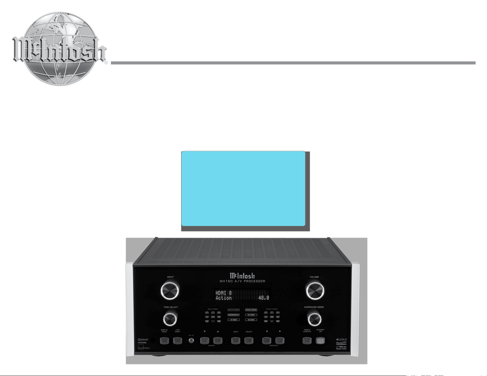
MX160
A/V Processor
Owner’s Manual
Important Safety Information is supplied in a separate document “Important Additional Operation Information Guide
”
Thank You
Your decision to own this McIntosh MX160 A/V
Processor ranks you at the very top among discriminating music listeners. You now have “The Best.” The
McIntosh dedication to “Quality,” is assurance that
you will receive many years of musical enjoyment
from this unit.
Please take a short time to read the information in
this manual. We want you to be as familiar as possible with all the features and functions of your new
McIntosh.
Please Take A Moment
The serial number, purchase date and McIntosh Dealer
name are important to you for possible insurance
claim or future service. The spaces below have been
provided for you to record that information:
Serial Number: _______________________________
Purchase Date: _______________________________
Dealer Name: ________________________________
Technical Assistance
If at any time you have questions about your McIntosh
product, contact your McIntosh Dealer who is familiar
with your McIntosh equipment and any other brands
that may be part of your system. If you or your Dealer
wish additional help concerning a suspected problem,
you can receive technical assistance for all McIntosh
products at:
McIntosh Laboratory, Inc.
2 Chambers Street
Binghamton, New York 13903
Phone: 607-723 -3512
Fax: 607-724-0549
2
Customer Service
If it is determined that your McIntosh product is in
need of repair, you can return it to your Dealer. You
can also return it to the McIntosh Laboratory Service
Department. For assistance on factory repair return
procedure, contact the McIntosh Service Department
at:
McIntosh Laboratory, Inc.
2 Chambers Street
Binghamton, New York 13903
Phone: 607-723 -3515
Fax: 6 07-723-1917
Table of Contents
Safety Instructions .............................................................. 2
(Separate Sheet) ............................Important Additional
Operation Information Guide
Thank You and Please Take a Moment ..............................2
Technical Assistance and Customer Service ......................2
Table of Contents ................................................................2
Trademark and License Information ..................................3
General Information ...........................................................4
Connector and Cable Information ......................................5
Introduction and Performance Features .............................6
Dimensions .........................................................................7
Installation ..........................................................................8
Connections:
Rear Panel Connections ...................................................... 9
Connections Diagram (Separate Sheet) ................. Mc1A
Zone A Input Connections................................................ 10
Connection Diagram (Separate Sheet) .................. Mc2A
Zone A 5.1 thru 7.1 Output Connections .......................... 11
Connection Diagram (Separate Sheet) ...................Mc2B
Zone A 5.1.4 thru 7.1.4 Output Connections .................... 11
Connection Diagram (Separate Sheet) .................. Mc3A
MX160 Zone B Output Connections ................................ 12
Connection Diagram (Separate Sheet) ...................Mc3B
Copyright 2017 © by McIntosh Laboratory, Inc.
Remote Control:
Push-buttons and How to use the Remote Control .....14 -15
Front Panel:
Front Panel Displays, Controls and Push-buttons ............ 16
Diagram (Separate Sheet) .......................................Mc1B
Setup Mode:
Introduction to the Setup Mode ................................... 17-18
Setup Functions:
Source Setup Menu ................................................... 19
Speaker and Room Setup Menu .......................... 20-22
Video Setup Menu ............................................... 23-24
Audio Setup Menu .................................................... 25
Zone B Setup Menu .................................................. 26
System Configuration Setup Menu ..................... 26 -27
Manage Software Setup Menu ................................. 27
RoomPerfect ............................................................................... 28
Operation:
How to Operate the MX160 .........................................30-35
Trim Functions:
Voi c i ng ..................................................................32 -33
Bass .......................................................................32-33
Treble .....................................................................32-33
VFD Level .............................................................32-33
Multi-View ............................................................32 -33
Lip Sync ................................................................ 32-33
Amp Light .............................................................32-33
Trim Center ........................................................... 32-33
Tri m LFE ............................................................... 32-33
Tri m Surrounds ..................................................... 32-33
Room Perfect .........................................................32-33
Surround Mode and Display Mode ................................... 34
Microprocessor Reset ........................................................ 35
How to Operate Zone B ...............................................36 -37
Advanced Setup and Operation ...................................38-39
Auxiliary Output and Electronic Crossover ............... 40 -41
Additional Information:
Specifications....................................................................42
Packing Instruction ........................................................... 43
Trademark and License Information
The McIntosh MX160 incorporates copyright protected technology that is protected by U.S. patents and
other intellectual property rights. The MX160 uses the
following Technologies:
Trademark and License Information
This item incorporates copy protection technology
that is protected by U.S. patents and other intellectual
property rights of Rovi Corporation. Reverse engineering and disassembly are prohibited.
Trademark Logo License Information
Manufactured under license from Auro Technologies.
Auro-3D® and the related symbols are registered
trademarks of Auro Technologies. All materials
contained in this work are protected by copyright law
and may not be reproduced, distributed, transmitted,
displayed, published or broadcast without the prior
written permission of Auro Technologies NV or in case
of third party materials, the owner of that content. You
may not alter or remove any trademark, copyright or
other notice from copies of the content.
Auro Technologies: mail info@auro-technologies.com,
phone +32-(0)-14314343, fax +32-(0)-14321224, www.
auro-technologies.com.
Manufactured under license from Dolby Laboratories.
Dolby, Dolby Atmos, Dolby Surround, and the
double-D symbol are trademarks of Dolby Laboratories.
For DTS patents, see http://patents.dts.com.
Manufactured under license from DTS, Inc. DTS,
the Symbol, DTS in combination with the Symbol,
DTS:X, and the DTS:X logo are registered trademarks
or trademarks of DTS, Inc. in the United States and/or
other countries. © DTS, Inc. All Rights Reserved.
Trademark Logo License Information
TM
HIGH-DEFINITION MULTIMEDIA INTERFACE
HDMI, the HDMI Logo and High-Denition
Multimedia Interface are trademarks or registered
trademarks of HDMI Licensing LLC in the United
States and other countries.
Manufactured under license from Lyngdorf Audio
A/S. ROOMPERFECT is a registered trademark and
the ROOMPERFECT logo is a trademark of Lyngdorf
Audio A/S. (C) Lyngdorf Audio A/S 2009.
Manufactured under license under U.S. Patent
Nos: 5,956,674; 5,974,380; 6,226,616; 6,487,535;
7,212,872; 7,333,929; 7,392,195; 7,272,567 & other
U.S. and worldwide patents issued & pending. DTSHD, the Symbol, & DTS-HD and the Symbol together
are registered trademarks & DTS-HD Master Audio is
a trademark of DTS, Inc. Product includes software. ©
DTS, Inc. All Rights Reserved.
3
General Information
1. For additional connection information, refer to the
owner’s manual(s) for any component(s) connected to the MX160 A/V Processor.
2. The Main AC Power going to the MX160 and
any other McIntosh Component(s) should not
be applied until all the system components are
connected together. Failure to do so could result
in malfunctioning of some or all of the system’s
normal operations. When the MX160 and other
McIntosh Components are in their Standby Power
Off Mode, the Microprocessor’s Circuitry inside
each component is active and communication is
occurring between them.
3. Sound Intensity is measured in units called Decibels and “dB” is the abbreviation.
4. LFE (Low Frequency Effects) refers to the Dolby
Digital or DTS sound channel dedicated to sound
effects (such as explosions) and is usually reproduced by the Subwoofer.
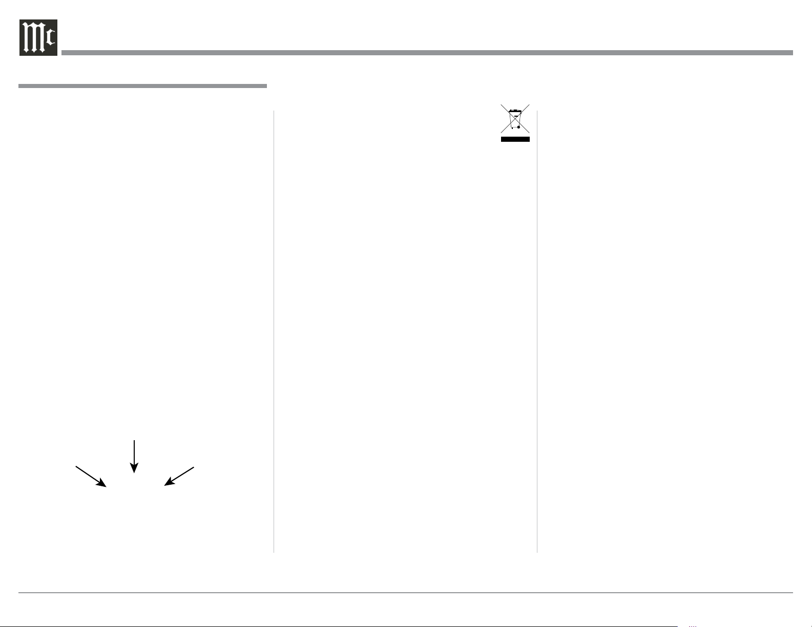
5. The MX160 processes Dolby Atmos, DTSX and Auro 3D Soundtracks. With these new
soundtracks there are additional discrete channels of sound present. In this Owner’s Manual the
number of channels are referred to as follows:
Number of
Subwoofer Channels
Number of
Ear Level Channels
Number of
Overhead Channels
7.1.4
6. The advanced Digital Sound Processing Circuitry
in the MX160 can output up to 12 discrete channels simultaneously, not including the four additional Subwoofer Outputs (Left and Right Front,
and Left and Right Rear); for a total of sixteen
channels.
7. When discarding the unit, comply with local rules
or regulations. Batteries should never be
thrown away or incinerated but disposed
of in accordance with the local regulations
concerning battery disposal.
8. The MX160 Owner’s Manual and supplied
Separate Information Sheets are also available in
electronic form (PDF) for download. Find them
and additional information on the MX160 and
other McIntosh Products by visiting the McIntosh
Web Site at www.mcintoshlabs.com.
9. MX160 is a two Zone Product (Zone A and Zone
B). This allows two different Audio Sources to be
available simultaneously for two separate rooms.
The Zone B Audio Stereo Output (which provides a two channel down mix from multichannel
sources) may also be used to provide an Audio
Signal for recording purposes, instead of an Audio
Signal to a second room. For more information
contact your McIntosh Dealer or McIntosh Technical Support.
10. The Zone A and Zone B IR Inputs, with 1/8 inch
mini phone jacks, are configured for non-McIntosh IR sensors such as a Xantech Model DL85K
Kit. Use a Connection Block such as a Xantech
Model ZC21 when two or more IR sensors need to
be connected to the MX160.
11. Setup Mode operations should be performed in
the order they appear in the Main Setup Menu
presented, as some adjustments are interactive.
12. In order to hear bass frequencies below 80Hz,
your system must include either a Subwoofer or
Large Front Loudspeakers.
13. The MX160 has built-in Digital Video Processing Circuitry to upconvert lower resolution Video
Signals to 4K Video Resolution.
General Information
14. HDMI Cable lengths between source components
and the MX160 should not exceed 25ft (8.3m). If
there is need to use HDMI Cables longer than 25ft
(8.3m) a high quality inline HDMI Buffer/Converter would be required for reliable digital signal
transmission via the HDMI Connections.
15. Use the MX160 HDBT OUT (HDBT is an HDMI
extender to squeeze uncompressed HDMI Signal
over one Ethernet CAT6 cable up to 70m long)
when the Cable length between the MX160 and
the Monitor/TV needs to exceed 25ft (8.3m) in
length.
16. The MX160 is designed to pass through a 3D
Digital Video Signal from a source component
to a 3D TV/Monitor via the HDMI Connections.
It is extremely important the HDMI cables used
for connections meet or exceed the HDMI High
Speed Cable Standards for proper 3D Video
Playback.
17. The Remote Control supplied with the MX160
A/V Processor is capable of operating other components. For additional information go to www.
mcintoshlabs.com.
18. When the MX160 and a PC Computer are connected to the same ethernet network, the Web
Interface built into the MX160 becomes available.
This allows Operational Control and Setup Mode
Functions, for the MX160, to be available on the
PC Computer for changes and adjustments. It
requires the latest version of the Internet Browser
(Firefox, etc.) to be installed on the PC. For additional information refer to “Advanced Operation
and Setup” on pages 38-39.
4
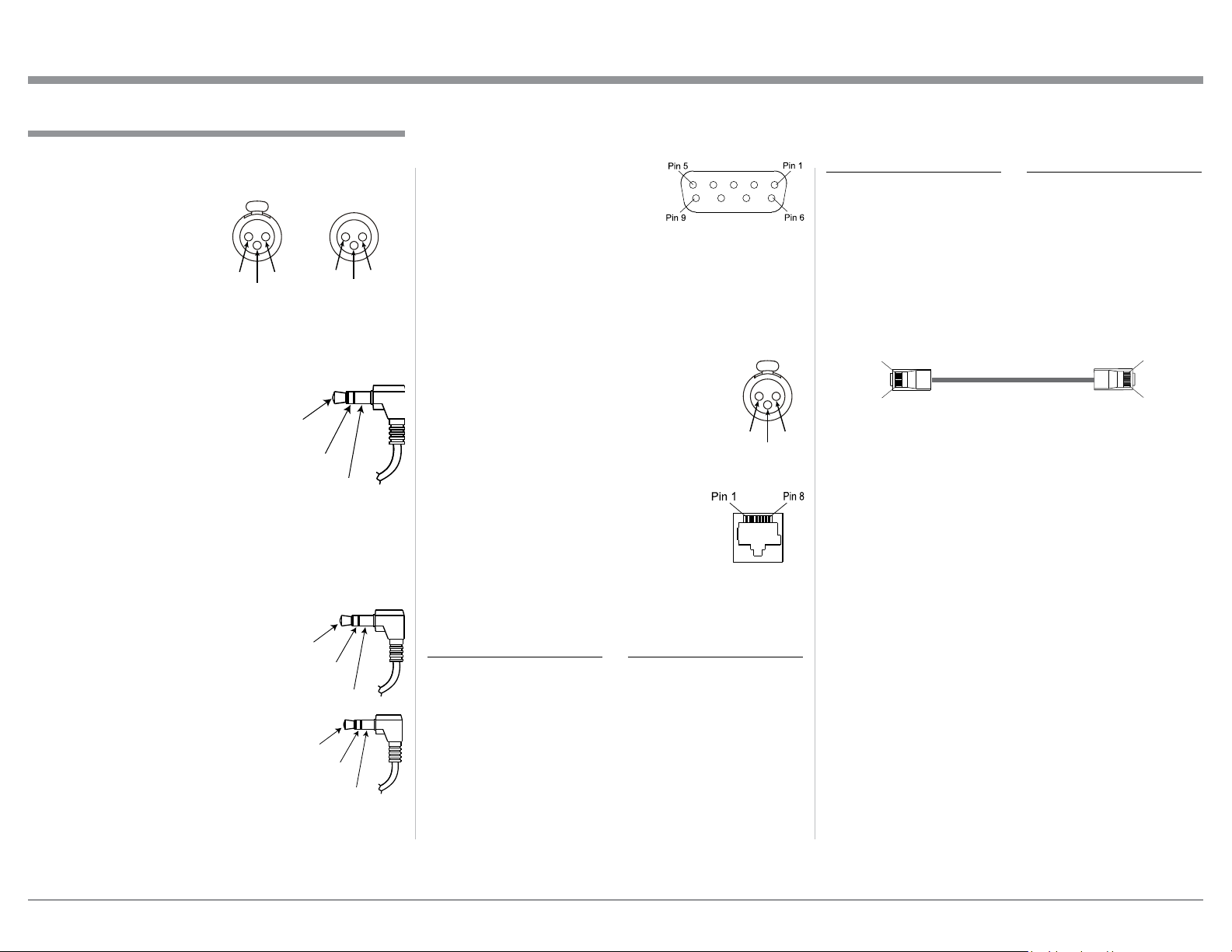
Connector and Cable Information
Ground
Pin 8
Pin 1
XLR Connectors
Below is the Pin configuration for the XLR Balanced
Output Connectors on the MX160. Refer to the diagrams for connections:
PIN 1: Shield/Ground
PIN 2: + Signal
PIN 3: - Signal
PIN 2 PIN 1
PIN 3
Power Control (Trigger) Connectors
The MX160 Power Control (Trigger) Output Jacks
send Power On/Off Signals when connected to other
Components. An additional
connection on the Main Power
Control Jack is for controlling
Power
Control
the illumination of the Power
Output Meters on McIntosh
Power Amplifiers. A 3.5mm
stereo mini phone plug is used for connection to the
Power Control (Trigger) Outputs on the MX160.
Data Output and IR IN Port Connectors
The MX160 Data Out Ports send Remote Control Signals to McIntosh Source Components. A 3.5mm stereo mini phone
plug is used for connection.
The IR IN Port also uses a 3.5mm
stereo mini phone plug and allows
the connection of other brand IR
Receivers to the MX160.
PIN 1
Meter
Illumination
Control
Data
Signal
N/C
IR Data
Control
N/C
PIN 3
Data
Ground
Ground
PIN 2
RS232 DB9 Connector Pin Layout
1. N/C 6. N/C
2. Data In (RXD) 7. N/C
3. Data Out (TXD) 8. N/C
4. N/C 9. N/C
5. Gnd.
Note: The use of a RS232 Crossover Cable or Cross-
over Adapter may be required.
Microphone XLR Connectors
Below is the Pin configuration for the Microphone
Connector on the MX160. Refer to the diagram for connections:
PIN 1: Shield/Ground
PIN 2: Signal
PIN 3: +8.9VDC
PIN 2 PIN 1
PIN 3
Ethernet RJ45 Socket
1. Transmit Data (+) 5. N/C
2. Transmit Data (-) 6. Receive Data (-)
3. Receive Data (+) 7. N/C
4. N/C 8. N/C
Ethernet Cable - Straight Thru Connections
Pin Number - Wire Color Pin Number - Wire Color
1. Orange/White → 1. Orange/White
2. Orange → 2. Orange
3. Green/White → 3. Green/White
4. Blue → 4. Blue
5. Blue/White → 5. Blue/White
6. Green → 6. Green
7. Brown/White → 7. Brown/White
8. Brown → 8. Brown
Connector and Cable Information
Ethernet Cable - Crossover Connections
Pin Number - Wire Color Pin Number - Wire Color
1. Orange/White → 1. Green/White
2. Orange → 2. Green
3. Green/White → 3. Orange/White
4. Blue → 4. Blue
5. Blue/White → 5. Blue/White
6. Green → 6. Orange
7. Brown/White → 7. Brown/White
8. Brown → 8. Brown
Pin 1
Pin 8
5
Introduction
The MX160 A/V Processor sets the standard of
excellence in a Home Theater System. The MX160
provides superior multichannel reproduction, RoomPerfect correction, the latest in digital audio decoding
and digital video conversion circuitry.
General Information, Cable Information, Introduction and Performance Features
Auro 3D Sound. It can also decode Dolby Upmixer,
DTS Neo:X and Cinema, Music and Game. Digital
Audio Streaming via the USB PC Input Streaming includes processing Digital Audio Signals up to 192kHz
with 24Bit resolution.
• Dual Zone
The MX160 has the built-in ability to control a separate remote audio/video zone with program selection
independent of Zone A, using a dedicated power
amplifier and speakers.
Performance Features
• HDMI Audio/Video Switching with UpConversion Processing
There are eight HDMI Inputs with Digital Video Conversion Circuitry with scaling of the video input signal
from 480p up to 2160p 4K Video Resolution.
• Input Selection
There are 7 Analog Audio Inputs (one eight channel),
8 Digital Audio Inputs and 8 Digital Video Inputs.
The MX160 has the ability to add 118 phantom Inputs
which can be titled and matched in level, so there are
no abrupt changes in volume levels between the different Inputs. Any unused input can be “turned off” so
the input selector will skip over it.
• Balanced Audio Inputs and Outputs
Two pair of Balanced high level Inputs and sixteen
channel Balanced Outputs allow long cable lengths
without a loss in sound quality.
• Moving Magnet Phono Input
There is a Precision Phono Preamplifier for Moving
Magnet Cartridges.
• Digital Audio Decoders
The MX160 also provides built-in decoding of the
latest Digital Audio Signal Audio/Video Formats
from Dolby, DTS and Auro 3D. These include Dolby
Atmos, Dolby True HD, DTS-X, DTS Master HD and
• On-Screen and Multifunction Fluorescent
Displays
A comprehensive On-Screen Display capability makes
it easy to perform setup and operational adjustments
using the Remote Control. The front panel display
indicates input selection, volume levels, and other
operating functions.
• LED Channel Status Indicators
The MX160 includes multiple LEDs on the Front
Panel to indicate what type of operating signals are
being received, signal processing mode and the output
format chosen.
TM
• RoomPerfect
Automatic Measurement
The RoomPerfect Automatic Measurement System
provides precise adjustment of Loudspeaker Volume
Levels, Time Delay and Equalization for all channels.
Supplied Calibrated Microphone with stand/boom
allows for the multiple room measurements for precise
adjustments.
• Digitally Controlled Audio Trim Functions
Audio Trim functions include Bass, Treble and Voicing (equalzation) adjustments, provide a wide range
of tone shaping with no loss in traditional McIntosh
sonic excellence.
• Fiber Optic Solid State Front Panel Illumination
The Illumination of the Glass Front Panel is accomplished by the combination of custom designed Fiber
Optic Light Diffusers and extra long life Light Emitting Diodes (LEDs). This provides even Front Panel
Illumination and is designed to ensure the pristine
beauty of the MX160 will be retained for many years.
• Power Control (Triggers) and Full Function Remote Control
The Power Control (Triggers) provides convenient
Turn-On/Off of components connected to the MX160.
The Remote Control Push-buttons provide complete
control of the MX160 operating functions.
• Machined Side Panels
The sides of the MX160 are machined from thick aluminum panels with a smooth black finish.
• Special Power Supply
The Power Supply has Multiple Regulators to ensure
stable noise free operation even though the power line
varies.
6
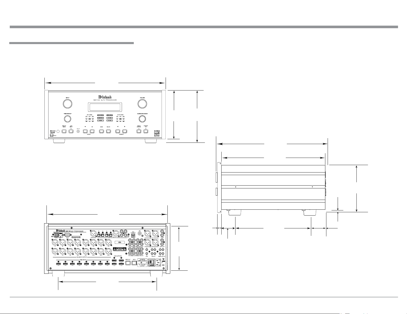
Dimensions
The following dimensions can assist in determining
the best location for your MX160.
Front View of the MX160
17-1/2"
44.5cm
HDMI 1
Neutral 12%
7-1/8"
18.1cm
Dimensions
7-5/8"
19.4cm
Side View of the MX160
16-1/2"
41.9cm
14-1/2"
36.8cm
Rear View of the MX160
17-1/8"
43.5cm
13 -1/4"
33.7cm
6-3/8"
16.2cm
13/16
2.1cm
"
1-15/16"
4.9cm
10-9/16"
26.8cm
3/16
0.5cm
5.1cm
"
2"
6-9/16"
16.7cm
7
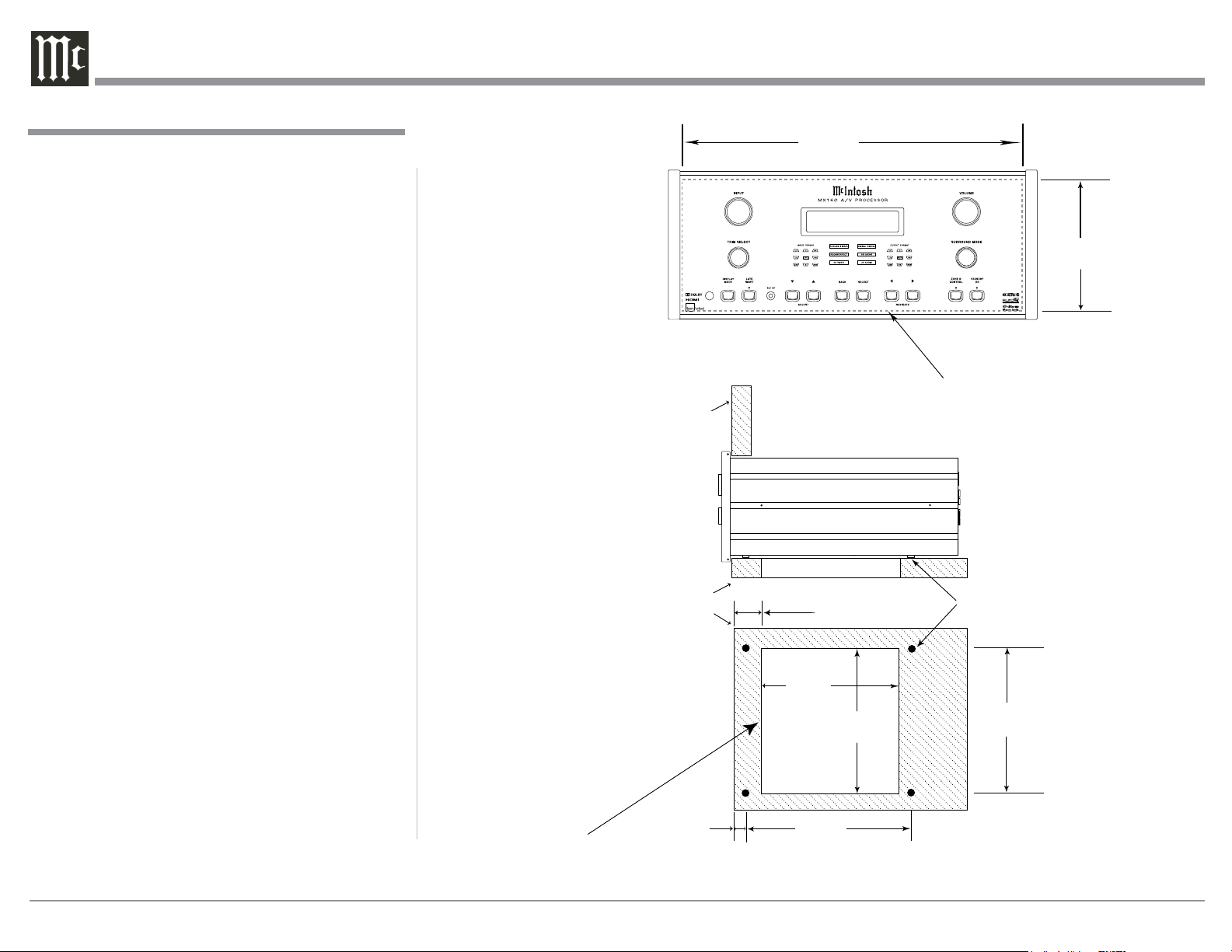
Installation
Installation
The MX160 can be placed upright on a table or
shelf, standing on its four feet. It also can be custom
installed in a piece of furniture or cabinet of your
choice. The four feet may be removed from the bottom
of the MX160 when it is custom installed as outlined
below. The four feet together with the mounting
screws should be retained for possible future use if the
MX160 is removed from the custom installation and
used free standing. The required panel cutout, ventilation cutout and unit dimensions are shown.
Always provide adequate ventilation for your
MX160. Cool operation ensures the longest possible
operating life for any electronic instrument. Do not
install the MX160 directly above a heat generating
component such as a high powered amplifier. If all
the components are installed in a single cabinet, a
quiet running ventilation fan can be a definite asset in
maintaining all the system components at the coolest
possible operating temperature.
A custom cabinet installation should provide the
following minimum spacing dimensions for cool
operation.
Allow at least 2 inches (5.1cm) above the top, 2
inches (5.1cm) below the bottom and 1 inch (2.5cm)
on each side of the Preamplifier, so that airf low is not
obstructed. Allow 20 inches (50.8cm) depth behind the
front panel. Allow 1-7/16 inch (3.7cm) in front of the
mounting panel for knob clearance. Be sure to cut out
a ventilation hole in the mounting shelf according to
the dimensions in the drawing.
MX160 Front Panel
Custom Cabinet Cutout
MX160 Side View
in Custom Cabinet
MX160 Bottom View
in Custom Cabinet
Cabinet
Front
Panel
Support
Shelf
17-3/16"
43.66cm
HDMI 1
Neutral 12%
Cutout Opening for Custom Mounting
Cutout Opening for Ventilation
2-1/4"
5.72cm
9-1/8"
23.18cm
Cutout
Opening
Ventilation
15"
38.10cm
for
6-9/16"
16.67cm
Chassis
Spacers
15"
38.10cm
1-1/16"
Note: Center the cutout Horizontally
on the unit. For purposes of
clarity, the above illustration
is not drawn to scale.
8
2.70cm
12-5/16"
31.27cm
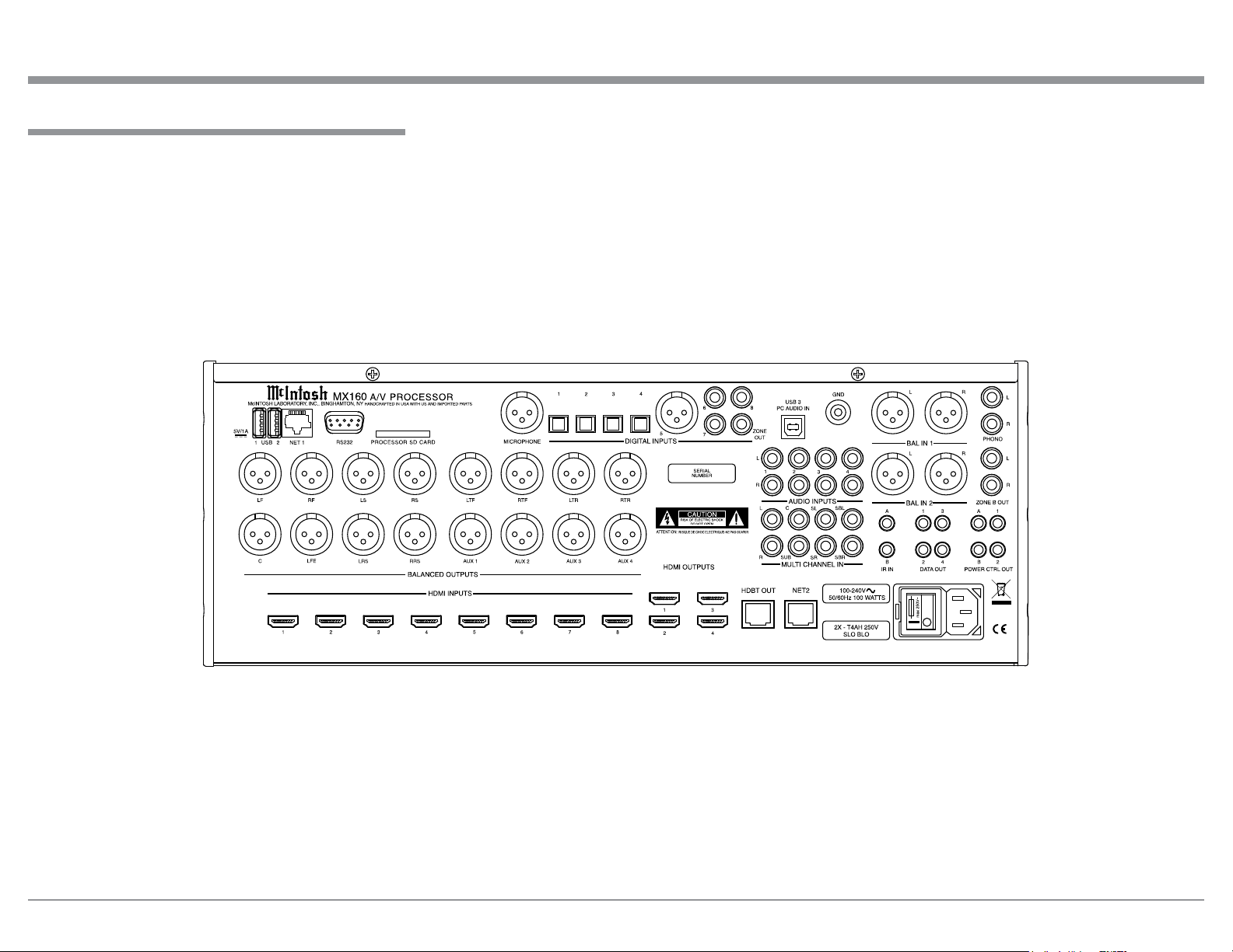
Rear Panel Connections
The identification of Rear Panel Connections for the
MX160 A/V Processor is located on a separate folded
sheet contained in the Owner’s Manual Packet.
Refer to separate sheet “Mc1A” for the Rear Panel
Connections.
Rear Panel Connections
MX160 A/V Processor Rear Panel
9
MX160 Zone A Input Connections
The MX160 has the ability to automatically switch
power On/Off to Source Components via the Power
Control (Trigger) connections. The Data Port Connections allow for the remote operation of basic functions
of McIntosh Source Componets using the MX160
Remote Control. With an external sensor(s) connected,
remote control operation of the system is possible.
The Zone A connection instructions below, together with the MX160 Input Connection Diagram located
on the separate folded sheets “Mc2A”, is an example
of a typical Home Theater System. Your system may
vary from this, however the actual components would
be connected in a similar manner. For additional information refer to “Connector and Cable Information”
on page 6.
Note: The following source component and sensor con-
nections made to the MX160 are using the default
settings starting on page 19. To make changes to
the default settings proceed to Setup Mode starting on page 17.
Power Control Connections:
1. Connect a Control Cable from the MX160 POWER CTRL (Control) A (Zone A) Jack to the Power
Control Remote In Jack on the Turntable.
2. Connect a Control Cable from the Turntable
Power Control Remote Out Jack to the Streaming
Audio Player Trigger In Jack.
3. Connect a Control Cable from the Streaming Audio Player Trigger Out Jack to the AM/FM Tuner
Power Control In Jack.
4. Connect a Control Cable from the AM/FM Tuner
Power Control Out Jack to the Audio/Video Disc
Player Power Control In Jack.
5. Connect a Control Cable from the Audio/Video
Disc Player Control Out Jack to the Media Bridge
PWR CTRL (Power Control) In Jack.
6. Connect any additional McIntosh Components in
a similar manner, as outlined in steps 1 thru 5.
7. Connect a Control Cable from the Media ServerPWR CTRL (Power Control) Out Jack to Power
Amplifier One Power Control In Jack.
Data Control Connections:
8. Connect a Control Cable from the MX160 DATA
OUT 1 Jack to the Media Server Data In Jack.
9. Connect a Control Cable from the MX160 DATA
OUT 2 Jack to the Audio/Video Disc Player Data
In Jack.
10. Connect a Control Cable from the MX160 DATA
OUT 3 Jack to the AM/FM Tuner Data In Jack.
11. Connect any additional McIntosh Components in a
similar manner, as outlined in steps 8 thru 10.
IR In Connections:
12. Optionally, connect the Control Cable from the
Zone A External Sensor to the MX160 IR IN A
(Zone A) Jack.
Note: Refer to page 5 for information on compat-
ible Sensors and page 6 for Cable/Connection
information.
13. Optionally, connect the Control Cable from the
Zone B External Sensor to the MX160 IR IN B
(Zone B) Jack.
Analog Audio Connections:
14. Connect Balanced Cables from the MX160 BALanced IN 1 Jacks to the Media Center Audio
Output Balanced Jacks.
15. Connect Audio Cables from the MX160 PHONO
Jacks to the Turntable Out Jacks.
Digital Audio Connections:
16. Connect a Digital Coaxial Cable from the MX160
DIGITAL INPUT 6 Coaxial Connector to the AM/
FM Tuner Digital Coaxial Output Connector.
MX160 Zone A Input Connections
17. Connect a Digital Optical Cable from the MX160
DIGITAL INPUT 7 Optical Connector to the
Streaming Audio Player Digital Optical Output
Connector.
HDMI Connections:
18. Connect a HDMI Cable from the MX160 HDMI
INPUT 1 Connector to the Satellite Receiver
HDMI Out Connector.
19. Connect a HDMI Cable from the MX160 HDMI
INPUT 2 Connector to the Media Server HDMI
Out Connector.
20. Connect a HDMI Cable from the MX160 HDMI
INPUT 3 Connector to the Audio/Video Disc
Player HDMI Out Connector.
Ground Connections:
21. Connect a Ground Cable from the MX160 GND
Binding Post to the Turntable GND Binding Post.
Computer/Network Connections:
22. Using a CAT 5/6 Ethernet Cable, connect the
cable from the Network Router/Switch to the NET
1 (Network) connector on the Rear Panel of the
MX160.
Note: If there is no Network Router/Switch available,
a computer may be connected to the MX160
Network Connectors NET 1 by using an Ethernet Crossover cable/adapter. Refer to “Connector and Cable Information” on page 6.
Proceed to Zone A Output Connections on the next
page.
10
MX160 Zone A Output Connections
The MX160 has the ability to automatically switch
power On/Off to a Power Amplifier via the Power
Control (Trigger) Connections.
The connection instructions below, together with
the MX160 Zone A Output Connection Diagram
located on the separate folded sheet “Mc2B” (an
example of a typical 5.1 thru 7.1 Channels using three
Power Amplifiers) and separate folded sheet “Mc3A”
(an example of a typical 5.1 thru 7.1.4 Channels using two additional Power Amplifiers) Home Theater
System. Your system may vary from this, however the
actual components would be connected in a similar
manner. For additional information refer to “Connector and Cable Information” on page 5.
Note: The following component connections made to
the MX160 are using the default settings. To make
changes to the default settings proceed to Setup
Mode starting on page 17.
5.1 THRU 7.1 CHANNEL CONNECTIONS:
Power Control Connections:
1. Connect a Control Cable from the Media Server
Power Control OUT Jack to the Power Control In
Jack on Zone A Power Amplifier One.
Note: Refer to separate folded sheet “Mc2A” and
page 11 step 7 for additional information.
2. Connect a Control Cable from Zone A Power Amplifier One Power Control Out to Zone A Power
Amplifier Two Power Control In Jack.
3. Connect a Control Cable from Zone A Power Amplifier Two Power Control Out 1 to Zone A Power
Amplifier Three Power Control In Jack.
4. Connect a Control Cable from Zone A Power Amplifier Three Power Control Out 1 to the Powered
Subwoofer Power Control In Jack.
5. Connect any additional McIntosh Components in a
similar manner, as outlined in steps 1 thru 4.
6. Connect a Control Cable from the Zone A Power
Amplifier Three, Power Control Out 2 Jack to
Zone A Power Amplifier Four Power Control In
Jack (used in a 5.1.4 or 7.1.4 Channel System).
Analog Audio Connections:
7. Connect Balanced Audio Cables from the MX160
LF (Left Front Channel), C (Center Channel) and
RF (Right Front Channel) to Zone A Power Amplifier One Inputs 1, 2 and 3 respectively.
8. Connect Balanced Audio Cables from the MX160
LS (Left Surround Channel) and RS (Right Surround Channel) to Zone A Power Amplifier Two
Inputs Left and Right respectively.
9. Optional, connect Balanced Audio Cables from
the MX160 LRS (Left Rear Surround Channel)
and RRS (Right Rear Surround Channel) to Zone
A Power Amplifier Three Inputs Left and Right
respectively.
10. Connect a Balanced Audio Cable from the MX160
LFE (Low Frequency Effects, also referred to as
a “Subwoofer Out”) to the Powered Subwoofer
MONO Input.
HDMI Connections:
11. Connect a HDMI Cable from the MX160 HDMI
OUTPUT 1 Connector to the Zone A TV/Monitor
HDMI Input connector.
Notes: 1. When the system is either a 5.1 or 7.1 Chan-
nel Home Theater System proceed to step
16. If the Home Theater System consists of
5.1.4 or 7.1.4 Channels proceed to step 12.
2. When Zone B (Audio/Video in another
room) on the MX160 will be utilized, proceed to page 12 for information on making
the needed additional connections after all
the Zone A Power Amplifier connections
are completed.
MX160 Zone A Output Connections
5.1.4 THRU 7.1.4 CHANNEL CONNECTIONS:
Power Control Connections:
12. Connect a Control Cable from Zone A Power Amplifier Three Power Control Out 2 Jack (or Zone
A Power Amplifier Two Power Control Out 2) to
the Power Control In on Zone A Power Amplifier
Four.
13. Connect a Control Cable from Zone A Power
Amplifier Four Power Control Out Jack to Zone A
Power Amplifier Five to Power Control In Jack.
Analog Audio Connections:
14. Connect Balanced Audio Cables from the MX160
LTF (Left Top Front Channel) and RTF (Right Top
Front Channel) to Zone A Power Amplifier Four
Inputs Left and Right respectively.
15. Optional, connect Balanced Audio Cables from the
MX160 LTR (Left Top Rear Channel) and RTR
(Right Top Rear Channel) to Zone A Power Amplifier Five Inputs Left and Right respectively.
Proceed to Zone B Output Connections on the next
page when MX160 Zone B will be utilized. If Zone
B will not be used at this time perform step 16
below:
AC Power Cords Connections:
16. Connect the MX160 and any remaining components’ AC Power Cords to a live AC outlet.
11

MX160 Zone B Output Connections
In a typical MX160 two Zone Audio/Video System,
Source Components can share the same Power Control
(Trigger) and Data Port Connections. The two Zones
in the MX160 share the same Audio/Video Input Connections.
The MX160 Zone B Input Connection Diagram
(located on the separate folded sheet “Mc3B”) is an
example of a typical Zone B Second Room System.
Your system may vary from this, however the actual
components would be connected in a similar manner.
For additional information refer to “Connector and
Cable Information” on page 5.
Note: The following connections made to the MX160
are using the default settings. To make changes to
the default settings proceed to Setup Mode starting on page 17.
Power Control Connections:
1. Connect a Control Cable from the MX160 POWER
CTRL (Power Control) B OUT Jack to the Power
Control In on Zone B Power Amplifier One.
2. Connect any additional Components in a similar
manner, as outlined in step 1.
Analog Audio Connections:
3. Connect Audio Cables from the MX160 Zone B
OUT - L (Left Channel) and R (Right Channel) to
Zone B Power Amplifier Left and Right respectively.
Video Connections:
4. Connect a HDMI Cable from the MX160 HDMI
OUTPUT 2 Connector to the Zone B TV/Monitor
HDMI Input connector.
AC Power Cords Connections:
5. Connect the MX160 and any remaining components’ AC Power Cords to a live AC outlet.
MX160 Zone B Output Connections
Proceed to Remote Control Push-buttons on
page 14.
12
13
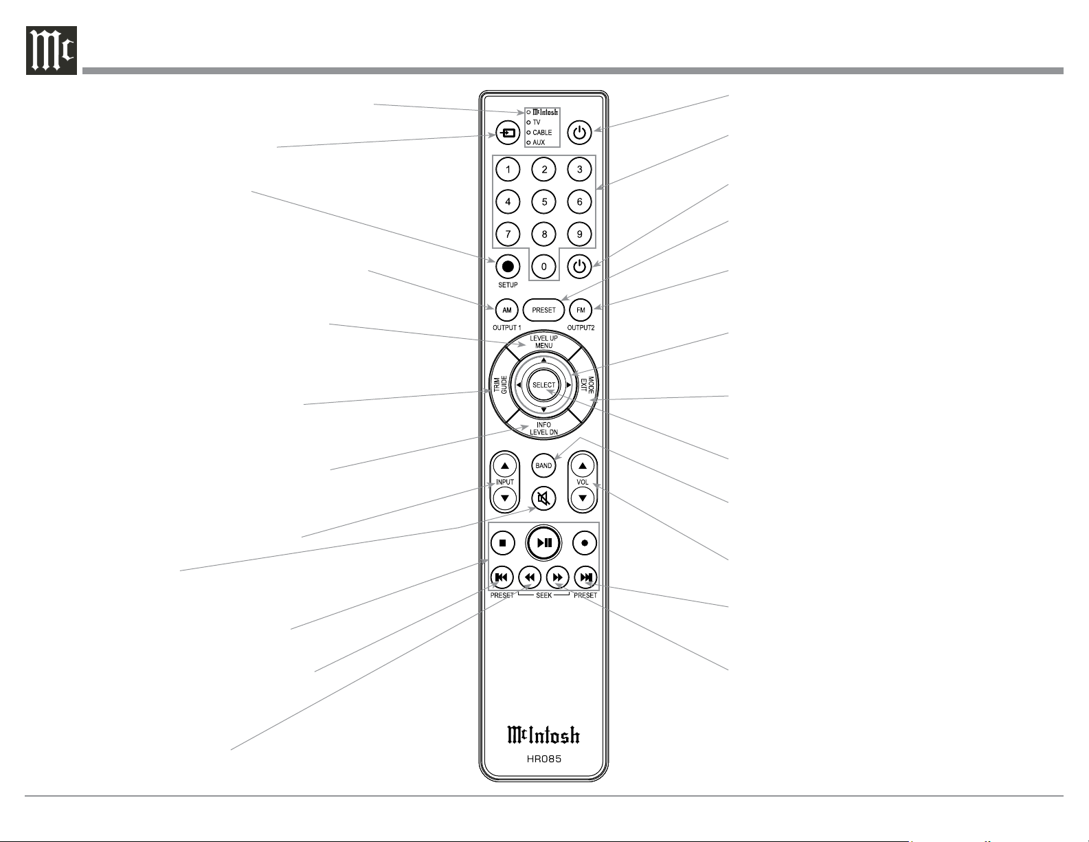
HR085 Remote Control Push-Buttons
LEDs illuminate during the time a remote command
is sent and when programming the remote control
Select the DEVICE to issue a remote
control command to
SETUP (Shift) Push-button
used to select a function with
blue color nomenclature
Selects AM Tuner Operating Functions (when connected to a McIntosh), also Track Selection on certain
McIntosh CD Players
Press the Trim Push-button and then the
LEVEL UP Push-button to select and adjust
various functions. MENU is used with McIntosh Models displaying choices on a video
screen.
Activates the TRIM Mode. GUIDE is
used with McIntosh Models displaying
instructions on a video screen.
Press the Trim Push-button and then the
LEVEL DOWN Push-button to select and
adjust various functions. INFO is used with
McIntosh Models displaying information on
a video screen.
Scrolls through the available INPUTS
Mutes the audio
Press to Power the amplifier ON
Use to select tuner presets, direct access an AM/FM Station Frequency,
disc tracks or any numbered operation
Press to Power the amplifier OFF
Direct access to stored Tuner PRESETS when
used with the numeric Push-buttons (0 thru 9)
Selects FM Tuner Operating Functions (when connected to a McIntosh), also Track Selection on certain
McIntosh CD Players
Use p and q to tune Up or Down the AM/FM
Dial, use u and t for the next or previous HD
Radio Program (McIntosh HD Tuner)
EXIT is used with McIntosh Models displaying
information or choices on a video screen
Used to SELECT/Enter the indicated choice
Press to change broadcast bands on a
connected Tuner. Select certain functions
on a variety of McIntosh Models
Adjusts the VOLume level up or down
14
Selects transport functions of STOP,
PLAY/PAUSE, RECORD, BACK for
the previous-selection, FAST-REVERSE, FAST-FORWARD and NEXT
for the next selection
Selects Previous Tuner Station PRESET
Tuner scans Down the dial
to SEEK the next Station
Selects Next Tuner Station PRESET
Tuner scans Up the dial to
SEEK the next Station
Note: Push-buttons whose function is not identified
above are for use with other McIntosh Products.
 Loading...