

McIntosh MX123 Owner's Manual
McIntosh Laboratory, Inc. 2 Chambers Street Binghamton, New York 13903-2699 Phone: 607-723-3512 www.mcintoshlabs.com
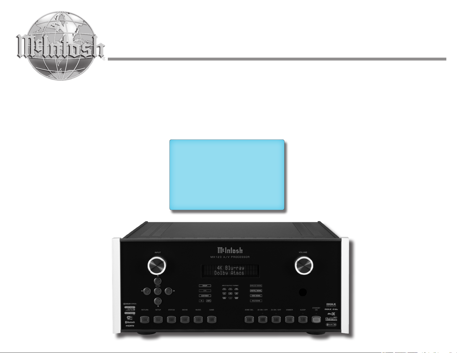
MX123
A/V Processor
Owner’s Manual
The MX123 Audio/Visual Processor marries a long
tradition of uncompromising quality with the latest home
theater technologies to bring you an unsurpassed luxury
entertainment experience.
Thank you from all of us at McIntosh
You have invested in a precision instrument that will
provide you with many years of enjoyment. Please take a
few moments to familiarize yourself with the features and
instructions to get the maximum performance from your
equipment.
If you need further technical assistance, please contact your
dealer who may be more familiar with your particular setup
including other brands. You can also contact McIntosh with
additional questions or in the unlikely event of needing
service.
Make a Note
McIntosh Laboratory, Inc.
2 Chambers Street
Binghamton, New York 13903
Technical Assistance: (607) 723-3512
Customer Service: (607) 723-3515
Fax:(607) 724-0549
Email: support@mcintoshlabs.com
Website: mcintoshlabs.com
For future reference, you can jot down your serial
number and purchase information here. We can
identify your purchase from this information if the
occasion should arise.
Serial Number:
Purchase Date:
Dealer Name
List of Figures
Figure 01– MX123 Dimensions ............................ 6
Figure 02– Custom cutout dimensions ................. 7
Figure 03– “L” bracket screws.............................. 7
Figure 04– MX123 Rear View ............................. 8
Figure 05– Mini plug for RS232 connection ....... 9
Figure 06– DB9 connector pin layout .................. 9
Figure 07– IR 3.5mm connector ........................... 9
Figure 08– Setting the Remote Control Lock ...... 9
Figure 09– Power control (trigger) mini plug ..... 11
Figure 10– Power control (trigger) mini plug ..... 11
Figure 11– MX123 Front panel ........................ 12
Figure 12– Display in Setup Mode ..................... 14
Figure 13– Browser Setup Menu ........................ 14
Figure 14– Sample Browser Warning screen ..... 15
Figure 15– Speaker Positions and abbreviations 17
Figure 16– Auro-3D layout example .................. 17
Figure 17– Dolby Atmos Enabled speakers ........ 18
Figure 18– Audyssey® main listening position .. 28
Figure 19– Speaker angles .................................. 28
Figure 20– Audyssey® Setup Start ...................... 29
Figure 21– Audyssey® Begi n Te s t ....................... 29
Figure 22– Speaker Detection ............................ 29
Figure 23– Microphone positioning ................... 29
Figure 24– Measurements complete ................... 30
Figure 25– Dynamic EQ..................................... 30
Figure 26– Audyssey® error message ................. 30
Figure 27– Audyssey® restore ............................. 30
Figure 28– Error table ....................................... 31
Figure 29– Re-packing diagram ......................... 34
Copyright 2019 © by McIntosh Laboratory, Inc
2

Table of Contents
Thank you from all of us at McIntosh ........................ 2
Make a Note ................................................................ 2
Safety First .................................................................. 4
Trademark and License Information ..........................5
What is in the box ....................................................... 6
Where to put it ............................................................ 6
Making the Cuts .......................................................... 7
Securing the MX123 to a Shelf ................................... 7
Connections on the Back ............................................ 8
The Inputs ......................................................... 8
The Outputs ...................................................... 8
Making Connections ................................................... 8
Bluetooth/Wi-Fi Antenna ................................. 8
10baseT L A N .................................................... 8
HDMI ............................................................... 9
USB .................................................................. 9
Microphone ....................................................... 9
RS232 ................................................................ 9
Wired IR Inputs ................................................ 9
Digital Inputs .................................................. 10
Analog Audio Inputs ....................................... 10
AC Power ........................................................ 10
Balanced Audio Outputs ................................. 10
Power Control (Trigger) Outputs .................... 11
Analog Audio Output ..................................... 11
Data Out .......................................................... 11
Setup Assistant .......................................................... 11
The Front Panel ......................................................... 12
Standby On .................................................... 12
The Input Knob ............................................... 12
The Volume Knob ........................................... 12
The Arrow and Enter Buttons ........................ 12
Status .............................................................. 13
Sound Mode Buttons ...................................... 13
Zone Select .................................................... 13
Zone On/Off ................................................... 13
Dimmer ........................................................... 13
Sleep Timer ..................................................... 13
Changing GUI Language/Video Format ........ 13
LED Channel Status Indicators ..................... 14
Setup ............................................................... 14
The Setup Menu ........................................................ 14
Browser Security Warning ............................. 15
Speakers- Setup Menu .................................... 15
Amp Assign .................................................... 15
Speaker Types and Positions ........................... 16
Speaker Configuration .................................... 17
Speaker Distances ........................................... 18
Speaker Levels ................................................ 18
Crossovers ....................................................... 18
Bass ................................................................. 18
Front Speaker .................................................. 19
2 Channel Playback ........................................ 19
Audio- Setup Menu ......................................... 19
Subwoofer Level Adjust .................................. 19
Bass Sync ........................................................ 19
Sound Parameter ............................................ 19
DFR ................................................................. 19
Audio Delay .................................................... 19
Volume Setup .................................................. 19
Audyssey® Options Menu................................ 20
Video- Setup Menu ......................................... 20
Picture Adjust ................................................. 20
HDMI Setup ................................................... 21
Output Settings .............................................. 21
HDMI Video Output ....................................... 21
Video Mode .................................................... 22
Video Conversion ........................................... 22
Analog Video Out ........................................... 22
On Screen Display .......................................... 22
4K Signal Format ............................................ 23
TV Format ...................................................... 23
Inputs Setup Menu .......................................... 23
Input Assign .................................................... 23
Source Rename ............................................... 23
Hide Sources ................................................... 23
Source Level ................................................... 23
Input Select ..................................................... 23
Network .......................................................... 24
General Setup ................................................. 24
Save & Load ................................................... 25
Description of Remote Control Buttons ................... 26
Fir mware ......................................................... 26
Remote Control Batteries ......................................... 28
Audyssey® ................................................................ 28
Audyssey® Setup ............................................ 28
Error Messages ............................................... 30
Factory Reset ............................................................ 31
Bluetooth ................................................................... 32
The Option Button .................................................... 32
The Headphone Question ............................... 32
Online Music ............................................................. 32
Spotify Connect ........................................................ 32
Compatible Audio Formats ....................................... 32
Supported Video Signals .......................................... 33
USB File and Folder Limits ...................................... 33
About ARC and CEC ................................................ 33
Packing the MX123 .................................................. 34
Audio Specifications ................................................ 35
Video Specifications ................................................. 35
General Specifications .............................................. 35
3

Safety First
Important Safety Information is supplied in a separate document “Important Additional Operation Information Guide”
FCC Information (For US Customers)
1. IMPORTANT NOTICE: DO NOT MODIFY
THIS PRODUCT
This product, when installed as indicated in the instructions contained in this manual, meets FCC requirements.
Modification not expressly approved by McIntosh may
void your authority, granted by the FCC, to use the
product.
2. CAUTION:
• To comply with FCC RF exposure compliance requirement, separation distance of at least 20cm must be
maintained between this product and all persons.
• This product and its antenna must not be co-located
or operating in conjunction with any other antenna or
transmitter.
3. COMPLIANCE INFORMATION:
• Product Name: A/V Processor
• Model Number: MX123
• This product contains FCC ID:RAX-AIOS4-0S:
McIntosh Laboratory, Inc.
2 Chambers Street
Binghamton, NY 13903
Tel. (607) 723-3512
IC Information (For Canadian Customers)
1. PRODUCT:
This product contains IC: 4711A-AIOS40S
This product complies with RSS-210 of Industry Canada.
Operation is subject to the following two conditions: (1)
this product may not cause harmful interference, and (2)
this product must accept any interference received, including interference that may cause undesired operation.
This Class B digital apparatus complies with Canadian
ICES-003.
2. CAUTION:
To reduce potential radio interference to other users, the
antenna type and its gain should be so chosen that the
equivalent isotropically radiated power (e.i.r.p.) is not
more than that permitted for successful communication.
Informations sur IC (pour les clients Canadiens)
1. APPAREIL:
Cet appareil contiens IC: 4711A-AIOS40S
Cet appareil est conforme à la norme CNR-210 du Canada. L’utilisation de ce dispositif est autorisée seulement
aux deux conditions suivantes : (1) il ne doit pas produire
de brouillage, et (2) l’utilisateur du dispositif doit être
prêt à accepter tout brouillage radioélectrique reçu,
même si ce brouillage est susceptible de compromettre
le fonctionnement du dispositif. Cet appareil numérique
de la classe B est conforme à la norme NMB-003 du
Canada.
2. ATTENTION:
Afin de réduire le risque d’interférence aux autres
utilisateurs, il faut choisir le type d’antenne et son gain
de façon à ce que la puissance isotrope rayonnée
équivalente (p.i.r.e.) ne soit pas supérieure au niveau req-
uis pour l’obtention d’une communication satisfaisante.
Canadian Customers: CAN ICES-3 (B)/NMB-3 (B)
RF Exposure Information
This equipment complies with FCC/IC radiation exposure limits set forth for an uncontrolled environment
and meets the FCC radio frequency (RF) Exposure
Guidelines in Supplement C to OET65 and RSS-102 of
the IC radio frequency (RF) Exposure rules. This equipment has very low levels of RF energy that are deemed
to comply without testing of specific absorption ratio
(SAR).
Cet équipement est conforme aux normes d’exposition
aux radiations FCC/IC définies pour un environnement
non contrôlé et satisfait les directives d’exposition à la
radiofréquence (RF) dans le supplément C des OET65
et RSS-102 des règles d’exposition à la fréquence radio
(RF) IC. Cet équipement a de très faibles niveaux
d’énergie RF qui sont jugés conformes sans test de taux
d’absorption spécifique (SAR).
R&TTE(EN) Information
1. DECLARATION OF CONFORMITY
Our products follow the provisions of EC/EU directives:
LV: 2006/ 9 5/EC
EMC: 2004/108/EC
RoHS: 2015/863/EU
ErP: EC regulation 1275/2008 and its frame work
directive 2009/125/EC
R&TTE Directive 1999/5/EC.
2. IMPORTANT NOTICE: DO NOT MODIFY
THIS PRODUCT
This product, when installed as indicated in the instructions contained in this manual, meets R&TTE directive
requirements. Modification of the product could result in
hazardous Radio and EMC radiation.
3. CAUTION:
Separation distance of at least 20cm must be maintained
between this product and all persons.
This product and its antenna must not be colocated or operating in conjunction with any other
antenna or transmitter.
4
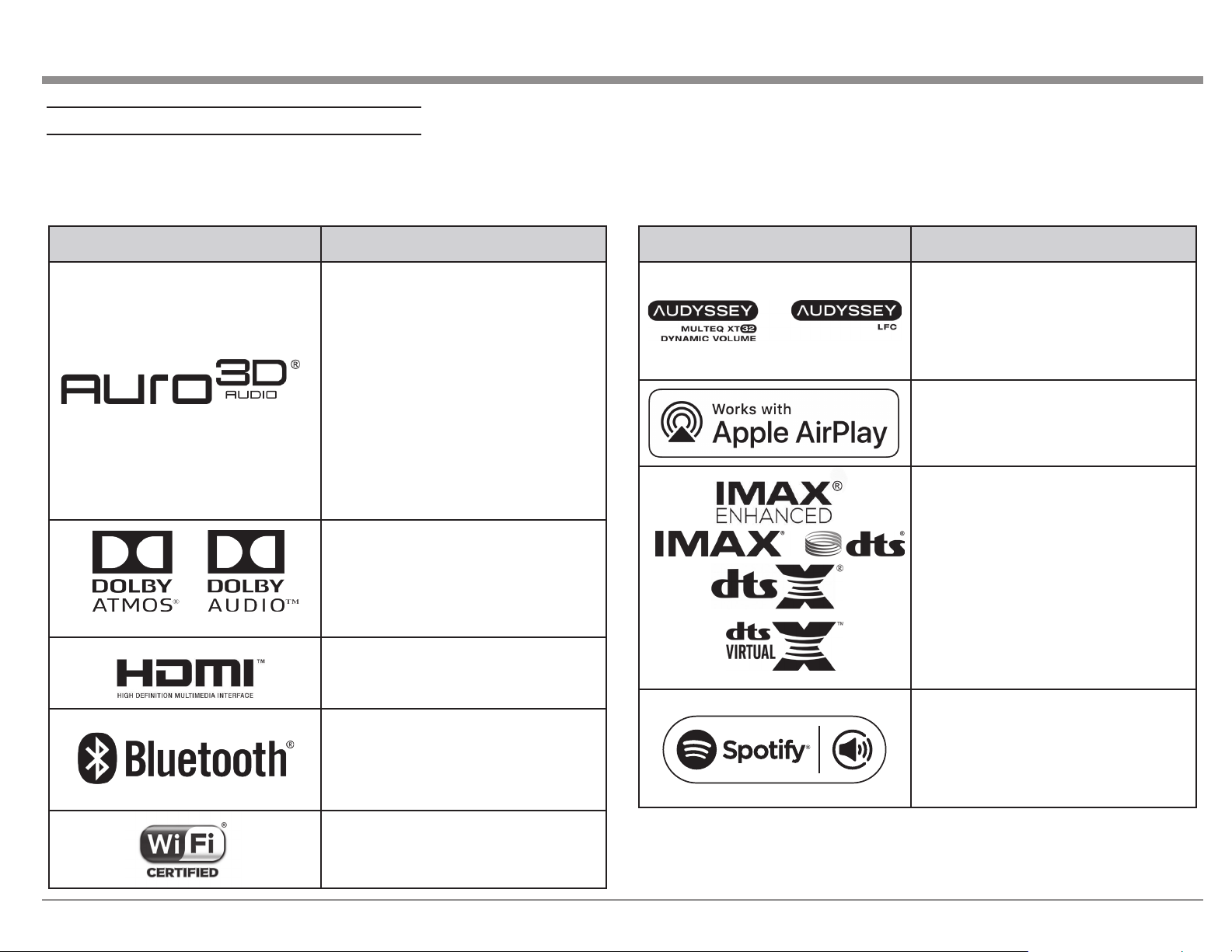
Trademark and License Information
The McIntosh MX123 incorporates copyright
protected technology that is protected by U.S. patents
and other intellectual property rights. The MX123
uses the following technologies:
This item incorporates copy protection technology
that is protected by U.S. patents and other intellectual
property rights of Rovi Corporation. Reverse
engineering and disassembly are prohibited.
Trademark Logo License Information
Manufactured under license from Auro
Technologies. Auro-3D® and the related
symbols are registered trademarks of Auro
Technologies. All materials contained in this
work are protected by copyright law and may
not be reproduced, distributed, transmitted,
displayed, published or broadcast without the
prior written permission of Auro Technologies
NV or in case of third party materials, the
owner of that content. You may not alter or
remove any trademark, copyright or other
notice from copies of the content.
Auro Technologies: mail info@aurotechnologies.com, phone +32-(0)-14314343,
fax +32-(0)-14321224, www.aurotechnologies.com.
Manufactured under license from Dolby
Laboratories. Dolby, Dolby Atmos, Dolby
Audio, Dolby Surround, Dolby Vision and
the double-D symbol are trademarks of Dolby
Laboratories.
HDMI, the HDMI Logo and High-Definition
Multimedia Interface are trademarks or
registered trademarks of HDMI Licensing LLC
in the United States and other countries.
The Bluetooth® word mark and logos are
registered trademarks owned by Bluetooth
SIG, Inc. and any use of such marks by
McIntosh Laboratory is under license. Other
trademarks and trade names are those of their
respective owners.
Trademark Logo License Information
Manufactured under license from Audyssey
Laboratories™. U.S. and
foreign patents pending. Audyssey MultEQ®
XT32, Audyssey Dynamic
EQ®, Audyssey Dynamic Volume® and
Audyssey LFC™ are registered
trademarks of Audyssey Laboratories.
Apple, AirPlay, iPad, iPad Air, iPad Pro, and
iPhone are trademarks of Apple Inc.,
registered in the U.S. and other countries. The
trademark “iPhone” is used in Japan
with a license from Aiphone K.K.
Manufactured under license from IMAX
Corporation. IMAX® is a registered trademark
of IMAX Corporation in the United States and/
or other countries.
Manufactured under license from DTS,
Inc. DTS, the symbol, DTS and the Symbol
together, DTS:X, the DTS:X logo, Virtual:X,
and the DTS Virtual:X logo are registered
trademarks and/or trademarks of DTS, Inc. in
the United States and/or other countries.
© DTS, Inc. All Rights Reserved.
The Spotify Software is subject to third party
licenses found here: https://www.spotify.com/
connect/third-party-licenses.
The Wi-Fi CERTIFIED Logo and the Wi-Fi
CERTIFIED On-Product Logo are
registered trademarks of the Wi-Fi-Alliance.
5
What is in the box
Front View of the MX123
Here is what is in the box besides all the shipping foam:
One MX123 A/V Processor
One accessory package including:
• Microphone with attached cable
• Microphone stand
• 1/2 inch male to 5/8 inch female adapter
• Two Bluetooth/Wi-Fi antennas
One hardware package:
• Two “L” Mounting brackets (for securing unit
to shelf)
• Two screws #6 x 1/2 inch
• Four #6 washers
One manual package including this manual
One AC power cord
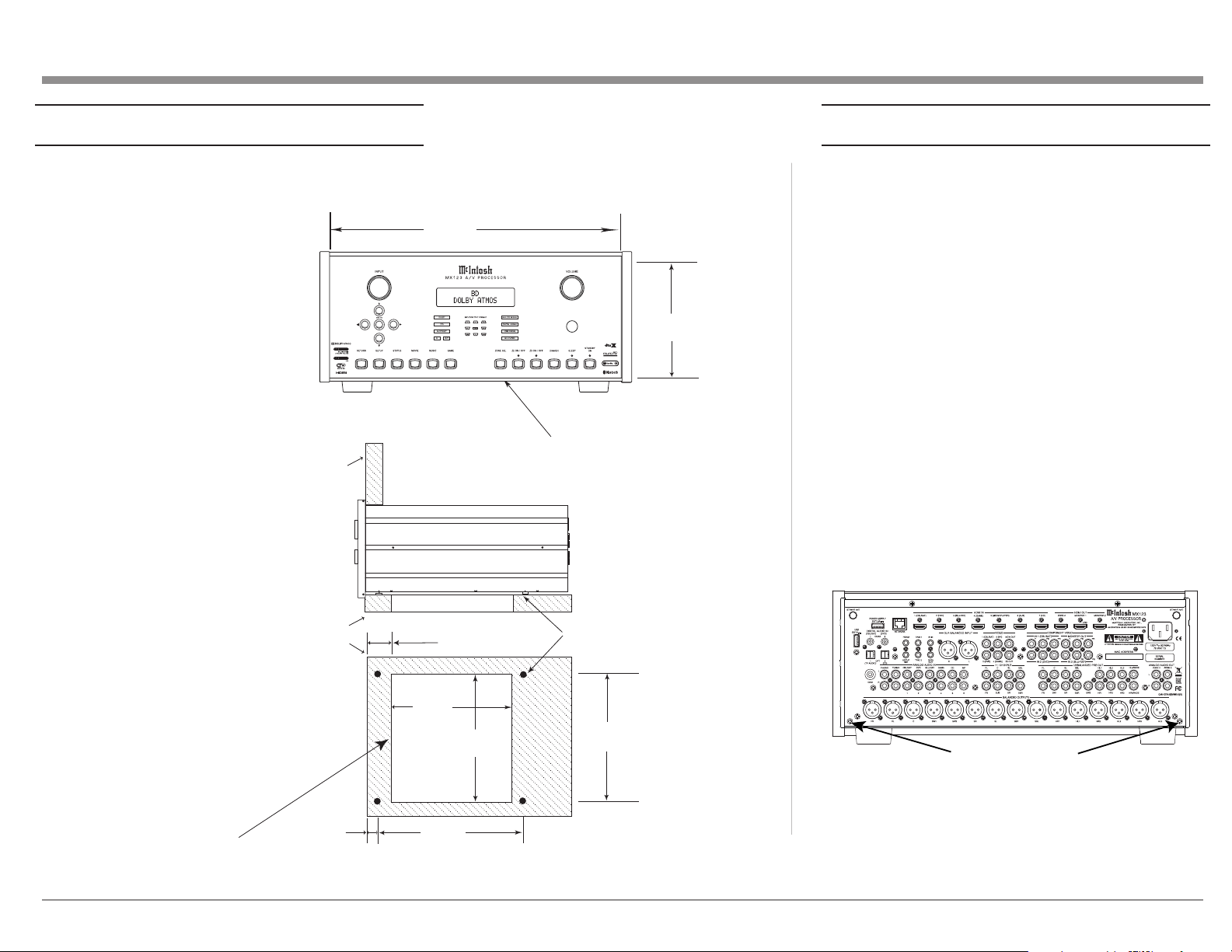
Where to put it
The MX123 can be placed upright on a table or
shelf, standing on its four feet. It also can be custom
installed in a piece of furniture or cabinet. The four
feet may be removed for custom installations. The
four feet together with the mounting screws should
be retained for possible future use. Do not use
different size screws when re-installing the feet. With
the feet removed, the MX123 requires a ventilation
cutout. Dimensions for the panel cutout and bottom
ventilation cutout are shown in Figure 02 on page
7.
Always provide adequate ventilation for your
MX123. Cool operation ensures the longest possible
operating life for any electronic instrument. Do not
install the MX123 directly above a heat generating
component such as a high-powered amplier. If all
the components are installed in a single cabinet, a
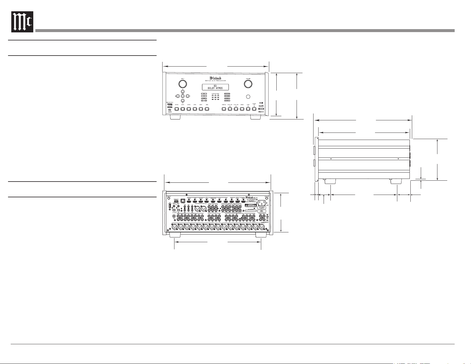
17-1/2"
44.5cm
6-3/8"
16.2cm
7-5/8"
19.4cm
Figure 01– MX123 Dimensions
Rear View of the MX123
17-1/8"
43.5cm
13 -1/4"
33.7cm
7-1/8"
18.1cm
quiet running ventilation fan can be a denite asset in
maintaining all the system components at the coolest
possible operating temperature.
A custom cabinet installation should provide the
following minimum spacing dimensions for cool
operation:
• 2 inches (5.1cm) above the top
• 2 inches (5.1cm) below the bottom
• 1 inch (2.5cm) on each side of the MX123 so
Side View of the MX123
16-1/2"
41.9cm
14-1/2"
36.8cm
3/16
0.5cm
13/16
2.1cm
"
1-15/16"
4.9cm
10-9/16"
26.8cm
5.1cm
that airow is not obstructed
• 20 inches (50.8cm) depth behind the front panel
• 1-7/16 inch (3.7cm) in front of the mounting
panel for knob clearance
Be sure to cut out a ventilation hole in the mounting
shelf according to the dimensions in the drawing. See
Figure 02 on page 7.
"
2"
6-9/16"
16.7cm
6
Making the Cuts
Securing the MX123 to a Shelf
Here are the dimensions for the cutouts needed for
custom installation. A ventilation opening is essential
MX123 Front Panel
Custom Cabinet Cutout
Cabinet
Front
Panel
MX123 Side View
in Custom Cabinet
for any installation with the four feet removed.
17-3/16"
43.66cm
6-9/16"
16.67cm
Cutout Opening for Custom Mounting
A hardware package containing two “L” brackets and
two screws along with four washers can be used to
secure the MX123 to a shelf.
To secure the MX123 to a shelf using the supplied “L”
brackets:
• Remove the two screws from the two lower
corners on the back of the MX123. See Figure
03.
• Attach the longer portion of the “L” bracket to
the rear of the MX123 using the same screw
just removed from the rear of the MX123 and
a supplied washer. Repeat for the other side.
Never use different size screws. The “L” bracket
should form a 90 degree angle with the lower
portion facing away from the rear of the unit
and resting on the shelf.
• Use the supplied screws and washers to attach
the lower portion of the “L” brackets to the
shelf.
MX123 Bottom View
in Custom Cabinet
Note: Center the cutout Horizontally
on the unit. For purposes of
clarity, the above illustration
is not drawn to scale.
Support
Shelf
1-1/16"
2.70cm
9
-1/8"
23.18cm
Cutout
Opening
for
Ventilation
12-5/16"
31.27cm
2-1/4"
5.72cm
Screws for attaching “L” brackets
Figure 03– “L” bracket screws
Figure 02– Custom cutout
dimensions
7
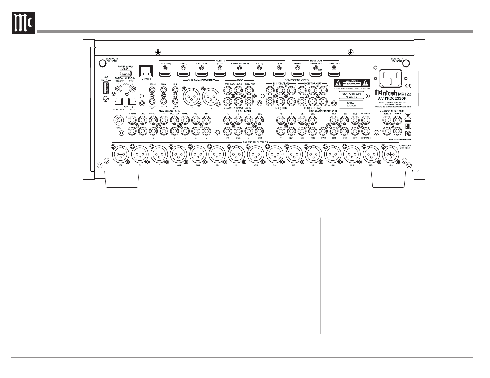
Connecons on the Back
The MX123 has a wealth of connections. They can be
divided into Inputs and Outputs.
The Inputs
Seven HDMI Inputs
One pair balanced XLR Inputs (AES/EBU)
Eight pairs RCA analog stereo Inputs including one
MM (moving magnet) RCA stereo pair and ground
connection
Two coaxial digital audio Inputs
Two Toslink optical Inputs
Four RCA video Inputs
Three sets of three component video RCA jacks
One 7.1 CH Input with eight analog RCA jacks
8
Figure 04– MX123 Rear View
One USB port to supply power
One USB port to connect storage
One 10baseT LAN connector
One 1/8 inch jack for microphone Input
One 1/8 inch jack for RS232 connector
One 1/8 inch jack for wired IR Input
One AC power connector
The Outputs
15 balanced XLR audio Outputs
17 unbalanced RCA Outputs
Two 1/8 inch jack Power Control (trigger) Outputs
Two RCA stereo pairs Output to two additional
zones
One set of three component video RCA Outputs
Two RCA video Outputs
One 1/8 inch Data Output jack
Making Connecons
Bluetooth/Wi-Fi Antenna
Attach the two Bluetooth/Wi-Fi antennas that
are included in the MX123 accessory package.
Each antenna screws into a connector labeled
BLUETOOTH/WI-FI ANT located in the top right
and left corners of the rear panel. After attaching the
antennas, point them upward.
10baseT LAN
Use an Ethernet cable to connect the MX123 to a
network router. The network connector is located
on the top left rear of the MX123. It is labeled
NETWORK. By default, the MX123 has DHCP set
to ON and will automatically receive an IP address
from the router. This setting can be changed. (See
“Network” on page 24.)
HDMI
The MX123 has 7 HDMI Inputs. A highperformance HDMI cable is recommended to take
advantage of the 18 Gbps speed capabilities of all
7 HDMI Inputs. The HDMI cables should support
4K@60Hz, HDR and YCbCr 4:2:2 (4:4:4/RGB)
as well as Ethernet and ARC. Cables designed for
HDMI 2.0 are ne. Though, HDMI is backward
compatible, older cables my have issues with the
higher bandwidth.
Use HDMI OUT MONITOR 1 when connecting to
an ARC (Audio Return Channel) enabled television.
ARC can provide two-way communication between
units allowing for volume control and lip-syncing
functions to ensure audio and video are perfectly
matched. This allows for more intelligent operation
between components as well as less cable clutter.
Make sure the ARC is enabled in your TV’s setup
menu.
USB
There are two type-A ports on the rear of the
MX123. The port labeled POWER SUPPLY is used
to supply power (5 volts / 1.5 amps) via a USB
cable. The second port, labeled USB, is for USB
memory devices. Use this second port for accessing
music from USB storage devices. Plug the USB
memory device directly into the port. USB hubs will
not work. Because of the vast array of USB memory
devices available from countless manufacturers,
McIntosh does not guarantee that all USB memory
devices will operate or receive power.
Microphone
The microphone Input is for connecting the supplied
MX123 Microphone using the microphone’s
attached cable and an 1/8 inch connector. The
microphone is used in the Audyssey® calibration for
tuning the system to your room. For instructions see
“Audyssey®” on page 28.
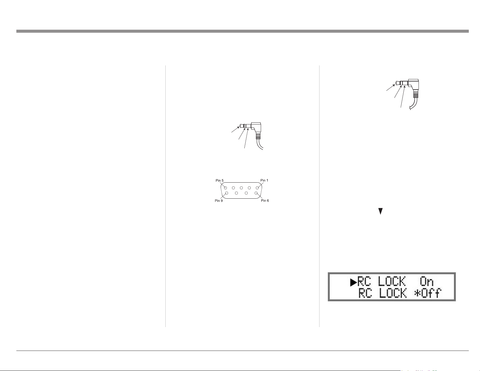
RS232
The RS232 jack is used to connect the MX123
to automation controller devices with RS232
connectors. To utilize this feature, you will need an
appropriate RS232 Data Cable. The RS232 Data
Cable should be an 1/8 inch (3.5mm) stereo mini
phone plug to a subminiature DB9 connector.
Data In
(DB9-pin2)
Data Out
(DB9-pin3)
Ground
(DB9-pin5)
Figure 05– Mini plug for RS232 connection
Figure 06– DB9 connector pin layout
RS232 DB9 Connector Pin Layout
1. N/C (no connection) 6. N/C
2. Data In (RXD) 7. N/C
3. Data Out (TXD) 8. N/C
4. N/C 9. N/C
5. Gnd
Typical RS232 settings are:
• 8 data bits, no parity and one stop bit
• Baud rate xed at 115,200 bits per second
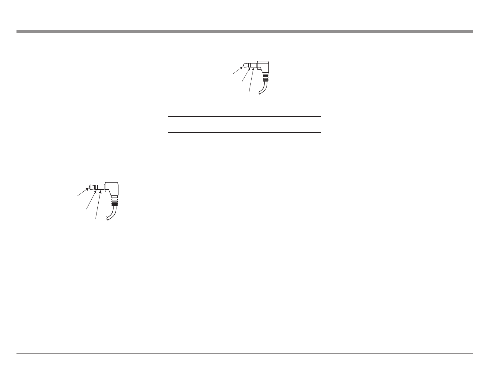
Wired IR Inputs
The IR Input allows an external IR receiver to be
attached to the MX123. The Input is labeled IR IN.
By attaching an IR receiver using a 3.5mm cable
(See Figure 07), the MX123’s Remote Control can
be used in another location without a line-of-sight to
the MX123’s front IR sensor. In this way, if ZONE
2 is another room, a Remote Control can be used to
adjust the MX123.
IR Data
Control
N/C
Ground
Figure 07–
IR 3.5mm connector
If using an external IR receiver for the MAIN
ZONE in the same room as the MX123, you may
wish to disable the front IR sensor, which also
controls the MAIN ZONE. This will avoid potential
timing issues of receiving the Remote Control’s
commands from two different Inputs. The front IR
can be turned on/off by doing the following:
• Put the MX123 in STANDBY mode
• While pressing and holding the front panel
ENTER and RETURN buttons, press the
STANDBY button (a 3-button push)
• Use the Down Arrow on the Front Panel or
Remote Control to navigate to the RC LOCK
Off option to enable the front panel IR sensor or
choose RC LOCK On to disable the front panel
IR sensor. See Figure 08
• Pushing ENTER will make the selection and
reboot the MX123
Figure 08– Setting the Remote Control Lock
9
Digital Inputs
There are four digital Inputs in the MX123:
• Two Toslink Optical Inputs
• Two Coaxial Digital audio Inputs
The two Coaxial Inputs are labeled:
• 1 (CBL/SAT)
• 2 (DVD)
The two Optical Inputs are labeled:
• 1 (TV AUDIO)
• 2 (CD)
The default names and assignments can be changed
in setup.
The Optical Inputs require a Digital Optical Audio
Cable Toslink Cable. The Coaxial Inputs use
Digital Audio Coaxial Cables with male RCA type
connectors.
Analog Audio Inputs
There are eight pairs of gold-plated RCA jacks. The
left jack of the stereo pair is on top, and the right
jack is below it. They are labeled as follows:
1. PHONO
2. TUNER
3. CBL/SAT
4. DVD
5. BLU-RAY
6. GAME
7. CD
8. MP
To the left of the PHONO jacks is a ground
connection labeled GND for connecting a
turntable’s ground wire. The PHONO section of the
MX123 is designed to work with Moving Magnet
cartridges.
There is one pair of Balanced XLR Inputs. It is
labeled XLR BALANCED Input. Looking at the
back of the unit, the Right Input is on the left and
the Left Input is on the right.
There are eight gold plated RCA jacks designed
for 7.1 Channel Input. They are located under the
heading 7.1 CH Input. They are labeled:
• FL (Front Left)
• FR (Front Right)
• C (Center)
• SUB (Subwoofer)
• SL (Surround Left)
• SR (Surround Right)
• SBL (Surround Back left)
• SBR (Surround Back Right)
All the Input names can be customized in the
SETUP program, as well as hidden and restored.
Hiding Inputs spares you from scrolling through
unused Inputs.
AC Power
This connection is essential. Plug the female end of
the supplied AC Power Cord into the AC connector
located in the rear right corner of the MX123. Plug
the male end of the AC Power Cord into a grounded
and functioning AC outlet.
Balanced Audio Outputs
There are 15 male balanced XLR connections on the
back of the MX123 to accommodate a wide variety
of speaker congurations. Connect balanced XLR
cables to the corresponding powered speakers or
ampliers. Here are the possible connections:
• FL (Front Left)
• FR (Front Right)
• C (Center)
• SW1 (Subwoofer 1)
• SW2 (Subwoofer 2)
• SR (Surround Right)
• SL (Surround Left)
• SBR (Surround Back Right)
• SBL (Surround Back left)
• HR1 (Height Right 1)
• HL1 (Height Left 1)
• HR2 (Height Right 2)
• HL2 (Height Left 2)
• HR3 (Height Right 3)
• HL3 (Height Left 3)
This is all easier said than done. Setting up speakers
for a surround setup takes planning, measuring and
installation. Depending on your level of expertise
and available time, you may wish to employ the
services of your McIntosh dealer for expert setup of
your system. Professional installation of in-ceiling
speakers is particularly important due to gravity and
the location above your head.
The number, types and locations of speakers are
key elements in setting up the system. There is
a multitude of possible congurations, and the
MX123 is very exible in its setup to adapt to many
of these congurations.
Often surround setups are referred to by numbers
for example 7.1.4 or 9.1.2. The rst number refers to
the number of traditional surround speakers (front,
center and surround). The second number is the
number of subwoofers that can be connected, and
the third number refers to the number of in-ceiling
or upward ring speakers in the setup.
The type of speaker (size and location) will be
entered later during Speaker setup. The distance
of the speaker from the listening location will be
entered in the Audyssey® setup. Make note of this
information.
10
At this stage, the connection from the MX123 to the
various ampliers and powered speakers should be
made using quality balanced XLR cables.
Power Control (Trigger) Outputs
The MX123 has two Power Control Outputs or
Triggers. Power Control enables power on/off
signals to go to connected components so that other
components can automatically power on (or off) as
called for by the MX123. For example, you may
want a DVD player and a certain monitor to power
on when HDMI 1 Input is selected, or you may want
all components to power off when powering off the
MX123. For Setup instructions see “General Setup”
on page 24.
Connect components using a 3.5mm stereo mini
plug. See Figure 09.
Power
Control
Meter
Illumination
Control
Figure 09– Power control (trigger) mini
Ground
plug
To connect a McIntosh unit to a Data Port, use a
3.5mm stereo mini phone plug cable. See Figure 10.
Data
Signal
N/C
Data
Ground
Figure 10– Power control (trigger) mini
plug
Setup Assistant
When the MX123 A/V Processor is initially
powered on (or after a Factory Reset- see page
31), the Setup assistant will appear on the Display
and a connected monitor. After choosing a language,
follow the guide’s instructions to setup your
Bluetooth/Wi-Fi Antenna Connection as well as
Network Setup. For more information on Network
Setup see “Network” on page 24.
Analog Audio Output
Two additional Zones labeled ZONE2 and ZONE3
can be fed analog signals using a pair of RCA
cables for each Zone. The jacks are located under
ANALOG AUDIO OUT on the right side of the rear
of the MX123.
Data Out
The MX123 will convert IR Remote Control data
to share with McIntosh components connected to
the Data Ports. This will allow units that are out of
range of an IR signal to receive commands.
11
 Loading...