

McIntosh MX122 Owner's Manual
McIntosh Laboratory, Inc. 2 Chambers Street Binghamton, New York 13903-2699 Phone: 607-723-3512 www.mcintoshlabs.com
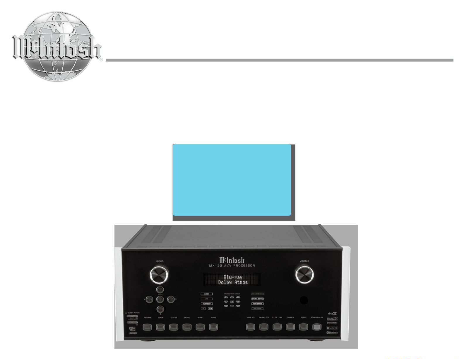
MX122
A/V Processor
Owner’s Manual

Important Safety Information is supplied in a separate document “Important Additional Operation Information Guide”
FCC Information (For US Customers)
1. IMPORTANT NOTICE: DO NOT MODIFY
THIS PRODUCT
This product, when installed as indicated in the instructions contained in this manual, meets FCC requirements.
Modication not expressly approved by McIntosh may
void your authority, granted by the FCC, to use the
product.
2. CAUTION:
• To comply with FCC RF exposure compliance requirement, separation distance of at least 20cm must be
maintained between this product and all persons.
• This product and its antenna must not be co-located or oper-
ating in conjunction with any other antenna or transmitter.
3. COMPLIANCE INFORMATION:
• Product Name: A/V Processor
• Model Number: MX122
• This product contains FCC ID:ZQO-CY92024C:
McIntosh Laboratory, Inc.
2 Chambers Street
Binghamton, NY 13903
Tel. (607) 723-3512
IC Information (For Canadian Customers)
1. PRODUCT:
This product contains IC: 2581A-CY92024C
This product complies with RSS-210 of Industry Cana-
da. Operation is subject to the following two conditions:
(1) this product may not cause harmful interference,
and (2) this product must accept any interference received, including interference that may cause undesired
operation. This Class B digital apparatus complies with
Canadian ICES-003.
2. CAUTION:
To reduce potential radio interference to other users, the
antenna type and its gain should be so chosen that the
equivalent isotropically radiated power (e.i.r.p.) is not
more than that permitted for successful communication.
Informations sur IC (pour les clients Canadiens)
1. APPAREIL:
Cet appareil contiens IC: 2581A-CY92024C
Cet appareil est conforme à la norme CNR-210 du
Canada. L’utilisation de ce dispositif est autorisée
seulement aux deux conditions suivantes : (1) il ne
doit pas produire de brouillage, et (2) l’utilisateur du
dispositif doit être prêt à accepter tout brouillage radioélectrique reçu, même si ce brouillage est susceptible
de compromettre le fonctionnement du dispositif. Cet
appareil numérique de la classe B est conforme à la
norme NMB-003 du Canada.
2. ATTENTION:
An de réduire le risque d’interférence aux autres
utilisateurs, il faut choisir le type d’antenne et son gain de
façon à ce que la puissance isotrope rayonnée
équivalente (p.i.r.e.) ne soit pas supérieure au niveau req-
uis pour l’obtention d’une communication satisfaisante.
Canadian Customers: CAN ICES-3 (B)/NMB-3 (B)
RF Exposure Information
This equipment complies with FCC/IC radiation exposure limits set forth for an uncontrolled environment and
meets the FCC radio frequency (RF) Exposure Guidelines
in Supplement C to OET65 and RSS-102 of the IC radio
frequency (RF) Exposure rules. This equipment has very
low levels of RF energy that are deemed to comply without
testing of specic absorption ratio (SAR).
Cet équipement est conforme aux normes d’exposition
aux radiations FCC/IC dénies pour un environnement
non contrôlé et satisfait les directives d’exposition à la
radiofréquence (RF) dans le supplément C des OET65
et RSS-102 des règles d’exposition à la fréquence radio
(RF) IC. Cet équipement a de très faibles niveaux
d’énergie RF qui sont jugés conformes sans test de taux
d’absorption spécique (SAR).
R&TTE(EN) Information
1. DECLARATION OF CONFORMITY
Our products follow the provisions of EC/EU directives:
LV: 2006/95/EC
EMC: 2004/108/EC
RoHS: 2011/65/EU
ErP: EC regulation 1275/2008 and its frame work
directive 2009/125/EC
R&TTE Directive 1999/5/EC.
2. IMPORTANT NOTICE: DO NOT MODIFY
TH IS PRODUCT
This product, when installed as indicated in the instruc-
tions contained in this manual, meets R&TTE directive
requirements. Modication of the product could result
in hazardous Radio and EMC radiation.
3. CAUTION:
Separation distance of at least 20cm must be maintained between this product and all persons.
This product and its antenna must not be co-located
or operating in conjunction with any other antenna or
transmitter.
2
Trademark and License Information
The McIntosh MX122 incorporates copyright protected technology that is protected by U.S. patents and
other intellectual property rights. The MX122 uses the
following Technologies:
This item incorporates copy protection technology
that is protected by U.S. patents and other intellectual
property rights of Rovi Corporation. Reverse engineering and disassembly are prohibited.
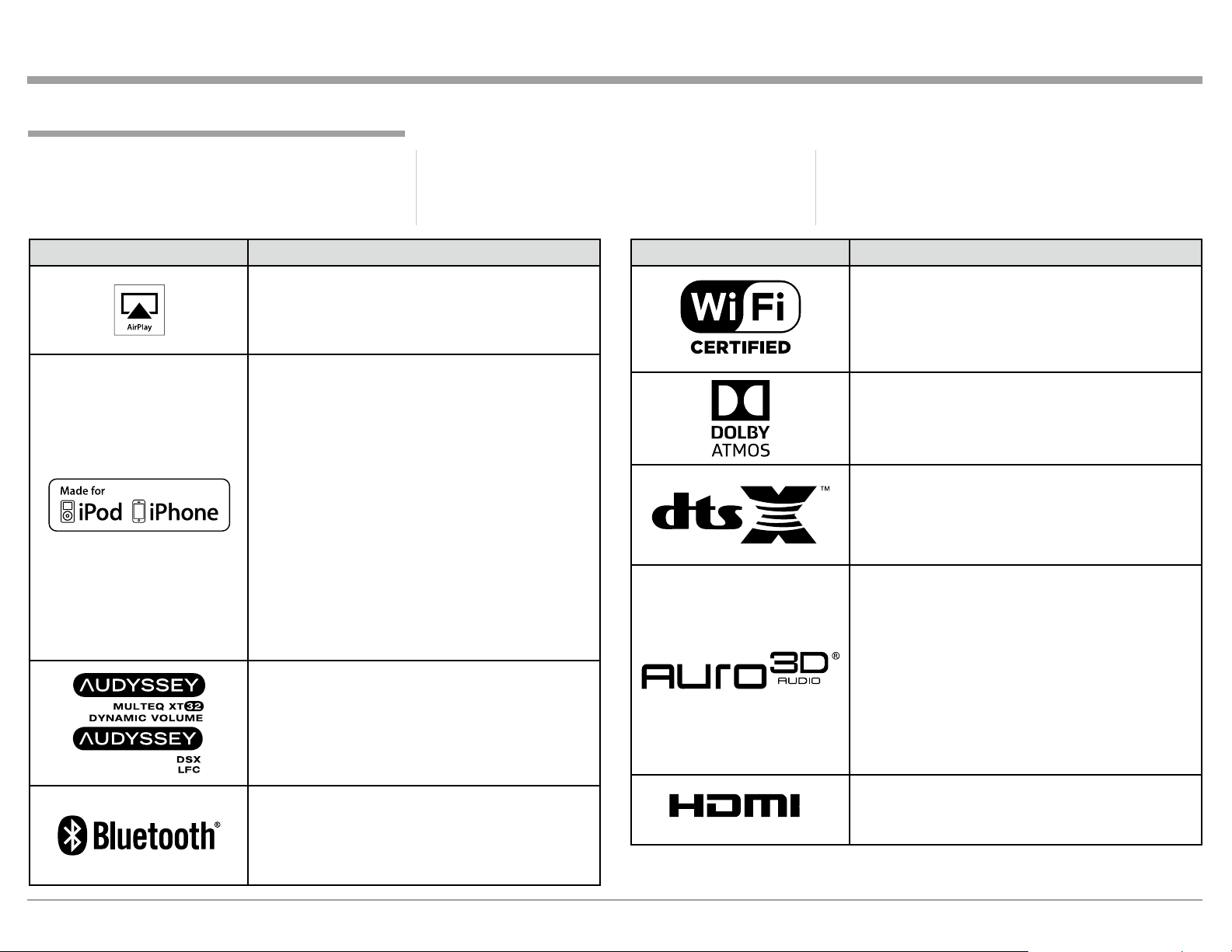
Trademark and License Information
PANDORA, the PANDORA logo, and the Pandora
trade dress are trademarks or registered trademarks of
Pandora Media, Inc. Used with permission.
Trademark Logo License Information
AirPlay®, the AirPlay logo, iPhone®, iPod®, iPod clas-
sic®, iPod nano®, iPod shufe®, iPod touch® and iPad
are trademarks of Apple Inc., registered in the U.S.
and other countries.
“Made for iPod” and “Made for iPhone” mean that
an electronic accessory has been designed to connect
specically to iPod or iPhone respectively, and
has been certied by the developer to meet Apple
performance standards.
Apple is not responsible for the operation of
this device or its compliance with safety and
regulatory standards. Please note that the use of this
accessory with iPod, or iPhone, may affect wireless
performance.
•iPhone, iPod, iPod classic, iPod nano, iPod shufe
and iPod touch are trademarks of Apple Inc.,
registered in the U.S. and other countries.
Individual users are permitted to use iPhone, iPod,
iPod classic, iPod nano, iPod shufe,and iPod touch
for private copy and playback of non-copyrighted
contents and contents whose copy and playback
is permitted by law. Copyright infringement is
prohibited by law.
Manufactured under license from Audyssey
Laboratories. U.S. and foreign patents pending.
Audyssey MultEQ® XT32, Audyssey Dynamic EQ®,
Audyssey Dynamic Volume® and Audyssey DSX®
and Audyssey LFCTM are registered trademarks of
Audyssey Laboratories.
The Bluetooth® word mark and logos are registered
trademarks owned by Bluetooth SIG, Inc. and any
use of such marks by McIntosh Group, Inc. is under
license. Other trademarks and trade names are those
of their respective owners.
Trademark Logo License Information
®
TM
HIGH-DEFINITION MULTIMEDIA INTERFACE
The Wi-Fi CERTIFIED logo is a registered trademark
of the Wi-Fi Alliance.
Wi-Fi Certication provides assurance that the device
has passed the interoperability test conducted by the
Wi-Fi Alliance, a group that certies interoperability
among wireless LAN devices.
Manufactured under license from Dolby Laboratories.
Dolby, Dolby Atmos, Dolby Surround, and the double-D symbol are trademarks of Dolby Laboratories.
For DTS patents, see http://patents.dts.com.
Manufactured under license from DTS, Inc. DTS,
the Symbol, DTS in combination with the Symbol,
DTS:X, and the DTS:X logo are registered trademarks
or trademarks of DTS, Inc. in the United States and/or
other countries. © DTS, Inc. All Rights Reserved.
Manufactured under license from Auro Technologies.
Auro-3D® and the related symbols are registered
trademarks of Auro Technologies. All materials
contained in this work are protected by copyright law
and may not be reproduced, distributed, transmitted,
displayed, published or broadcast without the prior
written permission of Auro Technologies NV or in case
of third party materials, the owner of that content. You
may not alter or remove any trademark, copyright or
other notice from copies of the content.
Auro Technologies: mail info@auro-technologies.com,
phone +32-(0)-14314343, fax +32-(0)-14321224,
www.auro-technologies.com.
HDMI, the HDMI Logo and High-Denition
Multimedia Interface are trademarks or registered
trademarks of HDMI Licensing LLC in the United
States and other countries.
3
Thank You
Your decision to own this McIntosh MX122 A/V
Processor ranks you at the very top among discriminating music listeners. You now have “The Best.” The
McIntosh dedication to “Quality,” is assurance that
you will receive many years of musical enjoyment
from this unit.
Please take a short time to read the information in
this manual. We want you to be as familiar as possible with all the features and functions of your new
McIntosh.
Please Take A Moment
The serial number, purchase date and McIntosh Dealer
name are important to you for possible insurance
claim or future service. The spaces below have been
provided for you to record that information:
Serial Number: _______________________________
Purchase Date: _______________________________
Dealer Name: ________________________________
Technical Assistance
If at any time you have questions about your McIntosh
product, contact your McIntosh Dealer who is familiar
with your McIntosh equipment and any other brands
that may be part of your system. If you or your Dealer
wish additional help concerning a suspected problem,
you can receive technical assistance for all McIntosh
products at:
McIntosh Laboratory, Inc.
2 Chambers Street
Binghamton, New York 13903
Phone: 607-723 -3512
Fax: 607-724-0549
Customer Service
If it is determined that your McIntosh product is in
need of repair, you can return it to your Dealer. You
can also return it to the McIntosh Laboratory Service
Department. For assistance on factory repair return
procedure, contact the McIntosh Service Department
at:
McIntosh Laboratory, Inc.
2 Chambers Street
Binghamton, New York 13903
Phone: 607-723 -3515
Fax: 6 07-723-1917
Table of Contents
Safety Instructions .............................................................. 2
(Separate Sheet) ............................Important Additional
Operation Information Guide
Trademark and License Information ..................................3
Thank You and Please Take a Moment ..............................4
Technical Assistance and Customer Service ......................4
Table of Contents ................................................................ 4
General Information ...........................................................5
Connector and Cable Information ......................................6
Introduction ........................................................................7
Performance Features ......................................................... 7
Dimensions .........................................................................8
Installation ..........................................................................9
Connections:
Rear Panel Connections .................................................... 10
Connections Diagram (Separate Sheet) .................. Mc1A
MX122 Main Zone Input Connections ............................ 11
Connection Diagram (Separate Sheet) ...................Mc2A
MX122 Main Zone Output Connections .......................... 12
Connection Diagram (Separate Sheet) .......Mc2B, Mc3A
MX122 Zone 2 Input and Output Connections ................ 13
Connection Diagram (Separate Sheet) ...................Mc3B
Copyright 2017 © by McIntosh Laboratory, Inc.
Front Panel:
Front Panel Displays, Controls and Push-buttons ............ 14
Diagram (Separate Sheet) ....................................... Mc1B
Remote Control:
Remote Control ................................................................. 15
Push-buttons Functioning (Separate Sheet) ..........Mc4A
Setup Mode:
Introduction to the MX122 Setup Mode ..................... 16-17
Audio Setup Menu ....................................................... 18-19
Video Setup Menu .......................................................19 -20
Inputs Setup Menu .......................................................20-21
Speaker Setup Menu .................................................... 21-22
Network Setup Menu ...................................................22-23
General Setup Menu ....................................................23-26
IR Sensor Settings ............................................................ 27
Initial Loudspeaker Setup ................................................28
Audyssey Auto Setup Information ................................... 29
Audyssey Auto Setup Procedure ................................. 30-31
Audyssey Error Messages ................................................32
Operation:
How to Operate the MX122 ........................................34 -37
iPod Playback and AirPlay ...................................... 37-38
USB Drive Playback .....................................................39
Internet Radio Radio ....................................................40
Special Internet Media Streaming ...........................41- 42
Media Server ................................................................. 43
MX122 PC Guide .............................................................44
Resetting the Micro and Factory Default Settings ........... 45
Additional Information:
Specifications....................................................................46
Packing Instruction ...........................................................47
4

General Information
Number of
7.1.4
General Information
1. For additional connection information, refer to the
owner’s manual(s) for any component(s) connected to the MX122 A/V Processor.
2. The Main AC Power going to the MX122 and
any other McIntosh Component(s) should not
be applied until all the system components are
connected together. Failure to do so could result
in malfunctioning of some or all of the system’s
normal operations. When the MX122 and other
McIntosh Components are in their Standby Power
Off Mode, the Microprocessor’s Circuitry inside
each component is active and communication is
occurring between them.
3. Sound Intensity is measured in units called Decibels and “dB” is the abbreviation.
4. LFE (Low Frequency Effects) refers to the Dolby
Digital or DTS sound channel dedicated to sound
effects (such as explosions) and is usually reproduced by the Subwoofer. To hear bass frequencies
below 80Hz, your system must include either a
Subwoofer or Large Front Loudspeakers.
5. The MX122 processes Dolby Atmos, DTS-X
and Auro-3D1 Soundtracks. With these new
soundtracks there are additional discrete channels of sound present. In this Owner’s Manual the
number of channels are referred to as follows:
Subwoofer Channels
Number of
Ear Level Channels
Number of
Overhead Channels
6. The advanced Digital Sound Processing Circuitry
in the MX122 can output up to 11.2 discrete channels simultaneously.
1
Auro-3D is not available for use in China and Japan. Auro-
3D Sound Tracks are up to 10.1 Channels of playback.
7. The number of Pre-Amplifier Channel Output
Connectors with Signals present is dependent
upon many factors including the number of loudspeakers and their physical location in the room.
The settings applied in the various MX122 Setup
Modes and Operation Modes will also have an effect. Lastly, Audio/Video Source Components and
program material itself will also determine the
number of active channels with signals present.
8. MX122 is a three Zone Product (Main Zone,
Zone 2 and Zone 3). This allows two different
Audio/Video Sources to be available simultaneously for two separate rooms. Zone 2 may be
used to provide an Audio/Video Output Signal for
recording purposes, instead of an A/V signal to a
second room. The Zone 3 (Audio Signal Sources
only) allows for listening to a different Audio
Source from either the Main Zone or Zone 2. For
more information contact your McIntosh Dealer
or McIntosh Technical Support.
9. The IR Input with 1/8 inch mini phone jack is
compatible with IR sensors such as a Xantech
Model DL85K Kit. Use a Connection Block such
as a Xantech Model ZC21 when two or more IR
sensors need to be connected to the MX122. To
avoid possible interaction, disable the MX122
Front Panel Sensor. Refer to page 27.
10. The DATA OUT Jack can be connected via a "Y"
Adapter to more than one McIntosh Source Com-
ponent DATA-IN Jack.
11. Setup Mode operations should be performed in the
order they appear in the first Setup Menu presented, as they are interactive.
12. The MX122 has built-in HDMI Digital Video
Selection and Digital Video Processing Circuitry
with Up Scaling capabilities to convert Composite
or Component Video Signals to Digital Video.
13. On-Screen Overlays, Operational Menus and
Setup Menu Functions are available on the HDMI
OUT Connectors.
14. The Component Video and Composite Video
Monitor Output Connectors provide a Video
Signal when a Component Video and Composite
Video Input Source with a signal present has been
selected.
15. HDMI Cable lengths should not exceed 25ft
(8.3m). If there is need to use HDMI Cables
longer than 25ft (8.3m) use a high quality inline
HDMI Buffer/Converter.
16. The MX122 is designed to pass through a 4K and
3D Digital Video Signal from a source component
to a 4K and/or 3D TV/Monitor via the HDMI
Connection that meets or exceeds the HDMI High
Speed Cable Standards (2.0).
17. The MX122 is compatible with the following
Apple Mobile Devices with the latest version of
the Apple OS Software installed:
iPod touch (5th generation) iPhone 5S
iPod touch (4th generation) iPhone 5C
iPod touch (3rd generation) iPhone 5
iPod touch (2st generation) iPhone 4S
iPod classic iPhone 4
iPod nano (7th generation) iPhone 3GS
iPod nano (6th generation) iPhone 3G
iPod nano (5th generation)
iPod nano (4th generation)
iPod nano (3rd generation)
18. The Remote Control Supplied with the MX122
A/V Processor is capable of operating other components. For additional information go to www.
mcintoshlabs.com.
19. For additional information on the MX122 and
other McIntosh Products please visit the McIntosh
Web Site at www.mcintoshlabs.com.
5
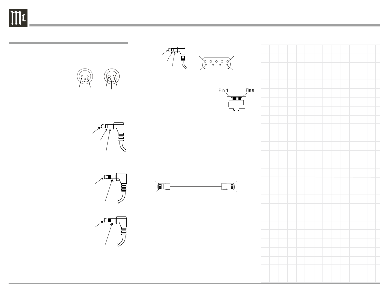
Connector and Cable Information
PIN 1
PIN 3
XLR Connectors
Below is the Pin configuration for the XLR Balanced
Output Connectors on the MX122. Refer to the dia-
N/C
Output
PIN 1
Ground
Ground
Ground
PIN 3
PIN 2
grams for connections.
Input
PIN 1: Shield/Ground
PIN 2: + Signal
PIN 3: - Signal
PIN 2
TRIGger (Power Control) Connectors
The MX122 Trigger Output Jacks send an On/Off
signal from 0 to +12 volts with a total current up to
50mA when connected to
other Components. A 3.5mm
stereo mini phone plug is
+12V DC
(Trigger
Control)
used for connection to the
Trigger Outputs on the
MX122.
Data Output
The MX122 Data Out sends
Remote Control Signals to
Source Components. A 3.5mm
Data
Signal
mini phone plug is used for
connection.
IR In Port Connector
The IR IN Port also uses a
3.5mm mini phone plug and al-
IR Data
Control
lows the connection of external
IR Receivers to the MX122.
RS232 Connector
The RS232 Data Cable is a 3.5mm stereo mini phone
plug to a subminiature DB 9 connector.
DB9
Data In
(DB9-pin2)
Data Out
(DB9-pin3)
Ground
(DB9-pin5)
(male connector)
PIN 1
PIN 6
PIN 5
PIN 9
Ethernet RJ45 Socket
1. Transmit Data (+) 5. N/C
2. Transmit Data (-) 6. Receive Data (-)
3. Receive Data (+) 7. N/C
4. N/C 8. N/C
Ethernet Cable - Straight Thru Connections
Pin Number - Wire Color Pin Number - Wire Color
1. Orange/White → 1. Orange/White
2. Orange → 2. Orange
3. Green/White → 3. Green/White
4. Blue → 4. Blue
5. Blue/White → 5. Blue/White
6. Green → 6. Green
7. Brown/White → 7. Brown/White
8. Brown → 8. Brown
Pin 8
Pin 1
Pin 1
Pin 8
Ethernet Cable - Crossover Connections
Pin Number - Wire Color Pin Number - Wire Color
1. Orange/White → 1. Green/White
2. Orange → 2. Green
3. Green/White → 3. Orange/White
4. Blue → 4. Blue
5. Blue/White → 5. Blue/White
6. Green → 6. Orange
7. Brown/White → 7. Brown/White
8. Brown → 8. Brown
Connector and Cable Information
6
Introduction
The MX122 A/V Processor sets the standard of excellence in a Home Theater System. The MX122 provides superior multichannel reproduction, Audyssey
®
Room correction, the latest in digital audio decoding
and digital video processing circuitry.
Performance Features
• Digital 4K and 3D Video Switching
There are seven HDMI 2.0a Inputs. Two Zone A
HDMI Outputs including Digital Audio Return
Channel (ARC) signal from the TV
the need for an extra cable and simplifies operation.
HDMI inputs are compatible with HDCP 2.2, Deep
Color, x.v.Color, Auto Lipsync and HDMI Component
Control.
• Analog Video/Audio Switching with Scaling
Component Video Inputs and Composite Video Inputs
(Analog Video Signals) are also converted to a Digital
Video Signal with resolution up to 4K at the HDMI
Outputs.
• Direct Access
There are 9 Analog (one eight channel input) and 11
Digital Audio Inputs along with 7 Analog and 7 Digi-
tal Video Inputs.
• Balanced Inputs and Outputs
A pair of Balanced high level Inputs and an 11.2 channel Balanced Output are provided, permitting long
cable lengths without a loss in sound quality.
• Moving Magnet Phono Input
There is a Precision Phono Preamplifier for Moving
Magnet Cartridges.
1
For TVs with ARC compatibility
1
, thus eliminating
Cable Information, Introduction and Performance Features
• Built-in Dolby Atmos, DTS-X and Auro-3D
Master Decoders
The MX122 also provides built-in decoding of the
Dolby True HD and DTS Master HD Sound Tracks.
• Internet Streaming
The MX122 when connected to a network, offers
Internet Radio, with music and photo streaming.
• On-Screen and Multifunction Fluorescent
Displays
A comprehensive On-Screen Display capability makes
it easy to perform setup and operational adjustments
using the Remote Control. The front panel display
indicates input selection, volume levels, and other
operating functions.
• LED Channel Status Indicators
The MX122 includes twenty-five LEDs on the front
panel to indicate what type of operating signals are
being received, signal processing mode and the output
format chosen.
• Audyssey DSX
Audyssey DSX is a scalable system that adds new
speakers to improve surround impression.
Audyssey DSX rst adds Wide channels for the
biggest impact on envelopment and then creates
Height channels to reproduce the next most important
acoustical and perceptual cues. Surround
Envelopment Processing is used to enhance the blend
between the front and surround channels.
• Digitally Controlled Volume and Tone Controls
A Precision Tracking Volume Control adjusts all
twelve channels with tracking accuracy better than
®
0.5dB. The Bass and Treble circuits provide a wide
range of tone shaping with no loss in traditional McIntosh sonic excellence.
• Triple Zones
The MX122 has the built-in ability to control a separate remote audio/video zone (Zone 2) with program
selection independent of the Main Zone, using a
dedicated power amplifier and speakers. There is also
a third Zone (Zone 3) providing a separate audio only
source to another room.
• Fiber Optic Solid State Front Panel Illumination
The Illumination of the Glass Front Panel is accomplished by the combination of custom designed Fiber
Optic Light Diffusers and extra long life Light Emitting Diodes (LEDs). This provides even Front Panel
Illumination and is designed to ensure the pristine
beauty of the MX122 will be retained for many years.
• Triggers and Full Function Remote Control
The Triggers (Power Control) provide convenient
Turn-On/Off of components connected to the MX122.
The Remote Control Push-buttons provide complete
control of the MX122 operating functions.
• Machined Side Panels
The sides of the MX122 are machined from thick aluminum panels with a smooth black finish.
• Special Power Supply
The Power Supply has Multiple Regulators to ensure
stable noise free operation even though the power line
varies.
7

Dimensions
The following dimensions can assist in determining
the best location for your MX122.
Front View of the MX122
17-1/2"
44.5cm
Dimensions
Rear View of the MX122
17-1/8"
43.5cm
7 -1/8"
18.1cm
6-3/8"
16.2cm
7 -5/8"
19.4cm
13/16"
2.1cm
1-15/16"
4.9cm
Side View of the MX122
16-1/2"
41.9cm
14-1/2"
36.8cm
10-9/16"
26.8cm
3/16"
0.5cm
5.1cm
6-9/16"
16.7cm
2"
13 -1/4"
33.7cm
8
Installation
is not drawn to scale.
The MX122 can be placed upright on a table or
shelf, standing on its four feet. It also can be custom
installed in a piece of furniture or cabinet of your
choice. The four feet may be removed from the bottom
of the MX122 when it is custom installed as outlined
below. The four feet together with the mounting
screws should be retained for possible future use if the
MX122 is removed from the custom installation and
used free standing. The required panel cutout, ventila-
tion cutout and unit dimensions are shown.
Always provide adequate ventilation for your
MX122. Cool operation ensures the longest possible
operating life for any electronic instrument. Do not
install the MX122 directly above a heat generating
component such as a high powered amplifier. If all
the components are installed in a single cabinet, a
quiet running ventilation fan can be a definite asset in
maintaining all the system components at the coolest
possible operating temperature.
When the MX122 is placed free-standing on a flat
surface, allow at least 2 inches (5.08cm) above the
top and 2 inches (5.08cm) on each side, so airf low is
not obstructed. Allow 19-1/2 inches (49.53cm) depth
behind the front panel. Allow 1-7/16 inch (3.66cm) in
front of the mounting panel for knob clearance.
A custom cabinet installation should provide the
minimum spacing dimensions for cool operation. Allow at least 2 inches (5.08cm) above the top, 2 inches
(5.08cm) below the bottom and 2 inches (5.08cm) on
each side, so airflow is not obstructed. The Custom
Cabinet should be open backed and at least 12 inches
(30.48cm) away from any surface such as a wall. Be
sure to cut out a ventilation hole in the mounting shelf
according to the dimensions in the drawing. Allow
1-7/16 inch (3.66cm) in front of the mounting panel for
knob clearance.
MX122 Front Panel
Custom Cabinet Cutout
MX122 Side View
in Custom Cabinet
MX122 Bottom View
in Custom Cabinet
Note: Center the cutout Horizontally
on the unit. For purposes of
clarity, the above illustration
Cabinet
Front
Panel
Support
Shelf
1-1/16"
2.7cm
17-3/16"
43.7cm
Cutout Opening for Custom Mounting
Cutout Opening for Ventilation
2-1/4"
5.7cm
9-1/8"
23.2cm
Cutout
Opening
Ventilation
15"
38.1cm
for
12-5/16"
31.3cm
Installation
6-9/16"
16.7cm
Chassis
Spacers
15"
38.1cm
9

Rear Panel Connections
The identification of Rear Panel Connections for the
MX122 A/V Processor is located on a separate folded
sheet contained in the Owner’s Manual Packet.
Refer to separate sheet “Mc1A” for the Rear Panel
Connections.
Rear Panel Connections
MX122 A/V Processor Rear Panel
10
MX122 Main Zone Input Connections
MX122 Main Zone Input Connections
The MX122 has the ability to automatically switch
power On/Off to Source Components via the Trigger (Power Control) Connections. With an external
sensor(s) connected, remote control operation of the
system is possible.
The Main Zone connection instructions below,
together with the MX122 Input Connection Diagram
located on the separate folded sheet “Mc2A”, is an example of a typical Home Theater System. Your system
may vary from this, however the actual components
would be connected in a similar manner. For additional information refer to “Connector and Cable Information” on page 6.
Note: The following source component and sensor con-
nections made to the MX122 are using the default
settings. To make changes to the default settings
proceed to Setup Mode starting on page 16.
Power Control Connections:
1. Connect a Control Cable from the MX122 TRIGger (Power Control) 1 Jack to the Power Control
Remote In on the Turntable.
2. Connect a Control Cable from the Turntable
Power Control Remote Out Jack to the Streaming
Audio Player Trigger In Jack.
3. Connect a Control Cable from the Streaming Audio Player Trigger Out Jack to the AM/FM Tuner
Power Control In Jack.
4. Connect a Control Cable from the AM/FM Tuner
Power Control Out Jack to the Audio/Video Disc
Player Power Control In Jack.
5. Connect a Control Cable from the Audio/Video
Disc Player Control Out Jack to the Media Server
PWR CTRL (Power Control) In Jack.
6. Connect any additional McIntosh Components in
a similar manner, as outlined in steps 1 thru 5.
7. Connect a Control Cable from the Media Server
PWR CTRL (Power Control) Out Jack to the Power Amplifier Main Zone Power Control In Jack.
Data Control Connections:
8. Connect a Control Cable from the MX122 DATA
OUT Jack to one end of a Stereo 3.5mm "Y"
adapter.
9. Connect a Control Cable from the AM/FM Tuner
DATA IN Jack to another end of the Stereo 3.5mm
"Y" adapter.
10. Connect a Control Cable from the Audio/Video
Disc Player DATA IN Jack to the remaining end
of the Stereo 3.5mm "Y" adapter.
IR In Connections:
11. Optionally, connect the Control Cable from the
External IR Sensor to the MX122 IR IN Main
Zone Jack.
Note: Refer to page 5 for information on compat-
ible Sensors and page 6 for Cable/Connection
information.
Analog Audio Connections:
12. Connect Balanced Cables from the MX122 XLR
BALANCED INPUT connectors to the Media
Server Audio Output Balanced connectors.
13. Connect Audio Cables from the MX122 PHONO
Jacks to the Turntable Out Jacks.
14. Connect Audio Cables from the MX122 TUNER
INPUT Jacks to the AM/FM Tuner UNBALanced
Output Jacks.
Digital Audio Connections:
15. Connect a Digital Coaxial Cable from the MX122
DIGITAL AUDIO IN COAX 2 (DVD) Optical
Connector to the Streaming Audio Player Digital
Coaxial Output Connector.
HDMI Connections:
16. Connect a HDMI Cable from the MX122 HDMI
INPUT 1 (CBL/SAT) Connector to the Satellite
Receiver HDMI Out Connector.
17. Connect a HDMI Cable from the MX122 HDMI
INPUT 5 (MEDIA PLAYER) Connector to the
Media Server HDMI Out Connector.
18. Connect a HDMI Cable from the MX122 HDMI
INPUT 3 (BLU-RAY) Connector to the Audio/
Video Disc Player HDMI Out Connector.
Ground Connections:
19. Connect a Ground Cable from the MX122 GND
Binding Post to the Turntable GND Binding Post.
Computer/Network Connections:
20. Using a CAT 5/6 Ethernet Cable, connect the
cable from the Network Router/Switch to the
NETWORK connector on the Rear Panel of the
MX122.
Note: If there is no Network Router/Switch available,
a computer may be connected to the MX122
Network Connector by using an Ethernet
Crossover cable/adapter. Refer to “Connector
and Cable Information” on page 6.
Proceed to Main Zone Output Connections on the
next page.
11
MX122 Main Zone Output Connections
MX122 Main Zone Output Connetions
The MX122 has the ability to automatically switch
power On/Off to the Power Amplifier via the Trigger
(Power Control) Connections.
The connection instructions below, together with
the MX122 Main Zone Output Connection Diagram
located on the separate folded sheet “Mc2B”, is an
example of a typical 5.1 thru 7.1 Channel Home Theater System using a Seven Channel Power Amplifier.
The separate folded sheet “Mc3A” is an example of a
typical 5.1.4 thru 7.1.4 Channel Home Theater System
using two additional Power Amplifiers. Your system
may vary from this, however the actual components
would be connected in a similar manner. For additional information refer to “Connector and Cable Information” on page 6.
Note: The following component connections made to
the MX122 are using the default settings. To make
changes to the default settings proceed to Setup
Mode starting on page 16.
5.1 THRU 7.1 CHANNEL CONNECTIONS:
Trigger (Power Control) Connections:
1. Connect a Control Cable from the Media Server
Power Control OUT Jack to the Power Control In
on the Main Zone Power Amplifier.
Note: Refer to separate folded sheet “Mc2A” and
page 11 step 7 for additional information.
2. Connect a Control Cable from the Main Zone
Power Amplifier Power Control Out to the Pow-
ered Subwoofer Power Control In Jack.
3. Connect any additional McIntosh Components in
a similar manner, as outlined in steps 1 thru 2.
4. Connect a Control Cable from the Powered Subwoofer Power Control Out Jack to the Main Zone
Power Amplifier Two Power Control In Jack (used
in a 5.1.4 or 7.1.4 Channel System).
Analog Audio Connections:
5. Connect Balanced Audio Cables from the MX122
LF (Left Front Channel), C (Center Chan-
nel), RF (Right Front Channel), SL (Surround
L e f t C h a n n e l ) , S R (S u r r o u n d R i g h t C h a n n e l )
to the Main Zone Power Amplifier matching
channels respectively.
6. Optional, connect Balanced Audio Cables from
the MX122 LRS (Left Rear Surround Channel)
and RRS (Right Rear Surround Channel) to the
Main Zone Power Amplifier, matching channels
respectively.
7. Connect a Balanced Audio Cable from the
MX122 SW1 (Low Frequency Effects Channel,
also referred to as a “Subwoofer Out”), to the
Powered Subwoofer MONO Input.
HDMI Connections:
8. Connect a HDMI Cable from the MX122 HDMI
OUTPUT 1 Connector to the Zone A TV/Monitor
HDMI Input connector.
Notes: 1. When the system is either a 5.1 or 7.1 Chan-
nel Home Theater System, proceed to step
13. If the Home Theater System consists of
5.1.4 or 7.1.4 Channels, proceed to step 9.
2. When Zone B (Audio/Video in another
room) on the MX122 will be utilized, proceed to page 14 for information on making
the needed additional connections after all
the Main Zone Power Amplifier connec-
tions are completed.
5.1.4 THRU 7.1.4 CHANNEL CONNECTIONS:
Power Control Connections:
9. Connect a Control Cable from the Powered Subwoofer Power Control Out Jack to the Power Control In on the Main Zone Power Amplifier Two.
10. Connect a Control Cable from the Main Zone A
Power Amplifier Two Power Control Out Jack to
the Main Zone A Power Amplifier Three Power
Control In Jack.
Analog Audio Connections:
11. Connect Balanced Audio Cables from the MX122
HR1 (Height Right 1 Front Channel) and HL1
(Height Left 1 Front Channel) to the Main Zone
Power Amplifier Two Inputs Left and Right respectively.
12. Optional, connect Balanced Audio Cables from
the MX122 HR2 (Height Right Rear Channel) and
HL2 (Height Left Rear Channel) to the Main Zone
Power Amplifier Three Inputs Left and Right
respectively.
Proceed to Zone B Output Connections on the next
page when MX122 Zone B will be utilized. If Zone
B will not be used at this time perform step 13
below:
AC Power Cords Connections:
13. Connect the MX122 and any remaining components’ AC Power Cords to a live AC outlet.
12
MX122 Zone 2 Output Connections
The MX122 has the ability to automatically switch
power On/Off to McIntosh Power Amplifiers via the
Power Control/Trigger connections.
The following connection instructions, together
with the MX122 Zone 2 Output Connection Diagram
located on the separate folded sheet “Mc3B”, is an
example of a typical Zone 2 Second Room System.
Your system may vary from this, however the actual
components would be connected in a similar manner.
For additional information refer to “Connector and
Cable Information” on page 6.
Note: The following component connections made to
the MX122 are using the default settings.
Power Control Connections:
1. Connect a Control Cable from the MX122 TRIGger (Power Control) 2 Jack to the Power Control In
on Zone 2 Power Amplifier.
Note: To assign the TRIGger 2 Output to activate when
Zone 2 is selected requires changes to the default
setting in the Setup Mode. Refer to page 25.
2. Connect any additional McIntosh Components in a
similar manner, as outlined in step 1.
Analog Audio Connections:
3. Connect Audio Cables from the MX122 ANALOG AUDIO OUT Zone 2 OUT Jacks - L (Left
Channel) and R (Right Channel) to Zone 2 Power
Amplifier Left and Right respectively.
Analog Video Connections:
4. Connect a HDMI Cable from the MX122 HDMI
OUT Zone 2 connector to the Zone 2 TV/Monitor
HDMI Input Connector.
AC Power Cords Connections:
5. Connect the MX122 and any remaining components’ AC Power Cords to a live AC outlet.
MX122 Zone 2 Input and Output Connections
13
Front Panel Display, Controls,
and Push-buttons
The identification of the MX122 A/V Processor Front
Panel Display, Controls, and Push-buttons is located
on a separate folded sheet contained in the Owner’s
Manual Packet. Refer to separate sheet “Mc1B”.
Front Panel Display, Controls, and Push-buttons
MX122 A/V Processor Front Panel
14
Remote Control Push-Buttons
The identification of Remote Control Push-Buttons
for the MX122 A/V Processor is located on a separate
folded sheet contained in the Owner’s Manual Packet.
Refer to separate sheet “Mc4A” for Push-button iden-
tification.
Remote Control Push-Buttons
15
 Loading...