

McIntosh MR-77 Owners manual
THE MclNTOSH MR 77 SOLID STATE FM/FM STEREO TUNER
Reading Time: 24 Minutes
Price $1.25


Your MR 77 FM/FM Stereo Tuner will give
you many years of pleasant and
satisfactory performance. If you have
any questions, please contact:
CUSTOMER SERVICE
Mclntosh Laboratory Inc.
2 Chambers Street
Binghamton, New York 13903
Phone: 607-723-3512
WARNING: TO PREVENT FIRE OR
SHOCK HAZARD, DO NOT EXPOSE
THIS UNIT TO RAIN OR MOISTURE.
Take Advantage of 3 years
of FREE Service ...
Fill in the Application NOW.
CONTENTS
SERVICE CONTRACT ... 1
INSTALLATION ... 2, 3
HOW TO CONNECT.. . 4
BACK PANEL INFORMATION ... 5, 6
FRONT PANEL INFORMATION ... 6, 7
LISTENING TO THE MR 77 ... 7
TECHNICAL DESCRIPTION ... 8, 9
PERFORMANCE LIMITS AND RATINGS ... 9
PERFORMANCE CHARTS ... 10, 11
BLOCK DIAGRAM ... 12
THREE YEAR SERVICE CONTRACT
An application for a FREE THREE YEAR SERVICE CONTRACT is included with this manual.
The terms of the contract are: or mishandling is not covered by the SER-
VICE CONTRACT.
4. The SERVICE CONTRACT is issued to you as
1. Mclntosh will provide all parts, materials and
labor needed to return the measured performance of the instrument to the original per-
formance limits free of any charge. The
SERVICE CONTRACT does not cover any ship-
ping costs to and from the authorized service
agency or the factory.
2. Any Mclntosh authorized service agency will
repair all Mclntosh instruments at normal
service rates. To receive the free service under the terms of the SERVICE CONTRACT, the
SERVICE CONTRACT CERTIFICATE must accompany the instrument when taken to the
service agency.
3. Always have service done by a Mclntosh
authorized service agency. If the instrument
is modified or damaged as a result of un-
authorized repair the SERVICE CONTRACT
will be cancelled. Damage by improper use
the original purchaser. To protect you from
misrepresentation this contract cannot be
transferred to a second owner.
5. For your protection Mclntosh selects only
dealers who have technical competence to
guide purchasers fairly, and provide service
when necessary. To receive the SERVICE
CONTRACT your purchase must be made
from a Mclntosh franchised dealer.
6. Your completely filled in application for a
SERVICE CONTRACT must be postmarked
within 30 days of the date of purchase of
the instrument.
7. To receive the SERVICE CONTRACT all information on the application must be filled
in. The SERVICE CONTRACT will be issued
when the completely filled in application
is received at Mclntosh Laboratory Incorporated in Binghamton, New York.
Copyright © 1970 By Mclntosh Laboratory Inc.
1
Installation
Adequate ventilation extends the trouble-free life of
electronic instruments. It is generally found that each
10° centigrade (18° F) rise in temperature reduces the
life of electrical insulation by one half. Adequate ventilation is an inexpensive and effective means of preventing insulation breakdown that results from unnecessarily high operating temperatures. The direct benefit
of adequate ventilation is longer, trouble-free life.
Allow at least 15 inches deep x 17½ inches wide x 6
inches high for mounting the MR 77. Always allow for air
flow by either ventilation holes or space next to the
bottom of the tuner and a means for warm air to
escape at the top.
It is recommended that the MR 77 be mounted in a
normal or horizontal position. However, with adequate
ventilation the tuner can be mounted in any position.
To prepare the MR 77 for installation remove the
plastic protective covering. Turn the MR 77 upside down
so that it rests on its top on the shipping pallet. Remove
the four plastic feet fastened to the bottom of the
chassis.
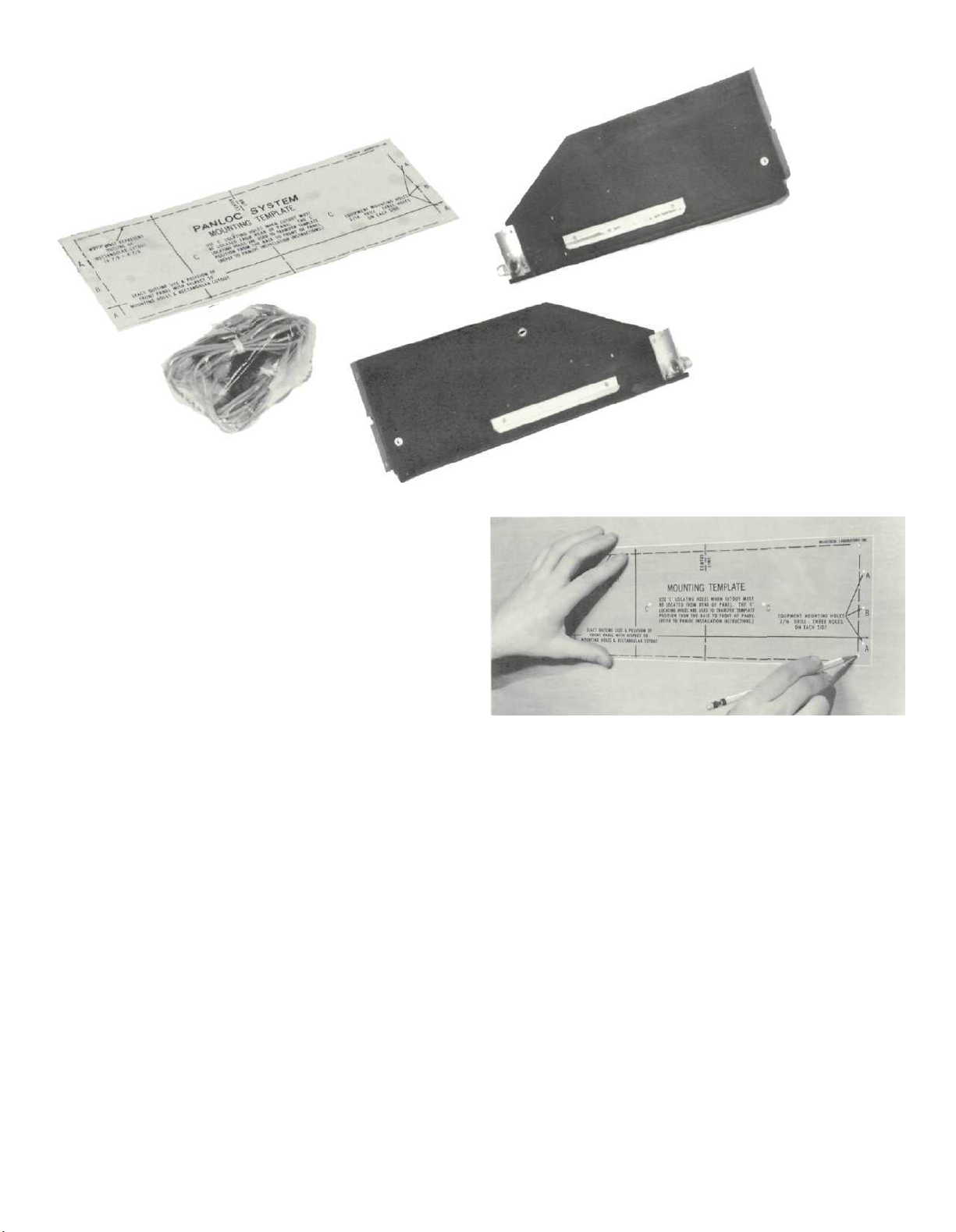
Next, place the mounting brackets, the parts bag
and the mounting template at hand.
The PANLOC professional mounting design elimi-
nates the need for any shelf or bracket to support the
MR 77. It is completely supported by its own mounting
brackets.
The design of the mounting template allows you to
position or locate the cutout from the front or rear of
the panel to which the instrument is to be mounted.
Position the plastic mounting template over the area of
the panel to be cut out for installation.
If the cutout is to be located from the front of the panel,
begin at step 2. If the cutout is to be located from the
rear of the panel, begin here.
1. On the back of the cabinet panel, scribe a vertical
centerline through the exact center of the area in
which the cutout is to be made.
Place the template against the back of the panel and
match the template centerline with the centerline on
the cabinet panel.
Make sure that there is at least ¼ inch clearance between the bottom of the dashed line of the cutout
area on the template and any shelf or brace below
the proposed cutout.
Mark the two locating holes ("C" holes on the
mounting template).
Drill the two locating holes. Be certain the drill is
perpendicular to the panel.
Now position the template on the front of the panel
by aligning the "C" locating holes on the template
with the drill holes.
2
2. If the cutout is to be located from the front of the
panel:
With the template in place against the cabinet, mark
the "A" and "B" drill holes and the four small holes
that identify the corners of the cutout. Join the cor-
ner marks with a pencil. The edge of the template
can be used as a straight edge.
IMPORTANT: DRILL THE 6 HOLES BEFORE MAKING
THE CUTOUT.
Accurately drill the three holes on each side of the
cutout area with a 3/16 inch drill.
With the saw on the INSIDE OF THE PENCIL LINES
carefully cut out the rectangular opening.
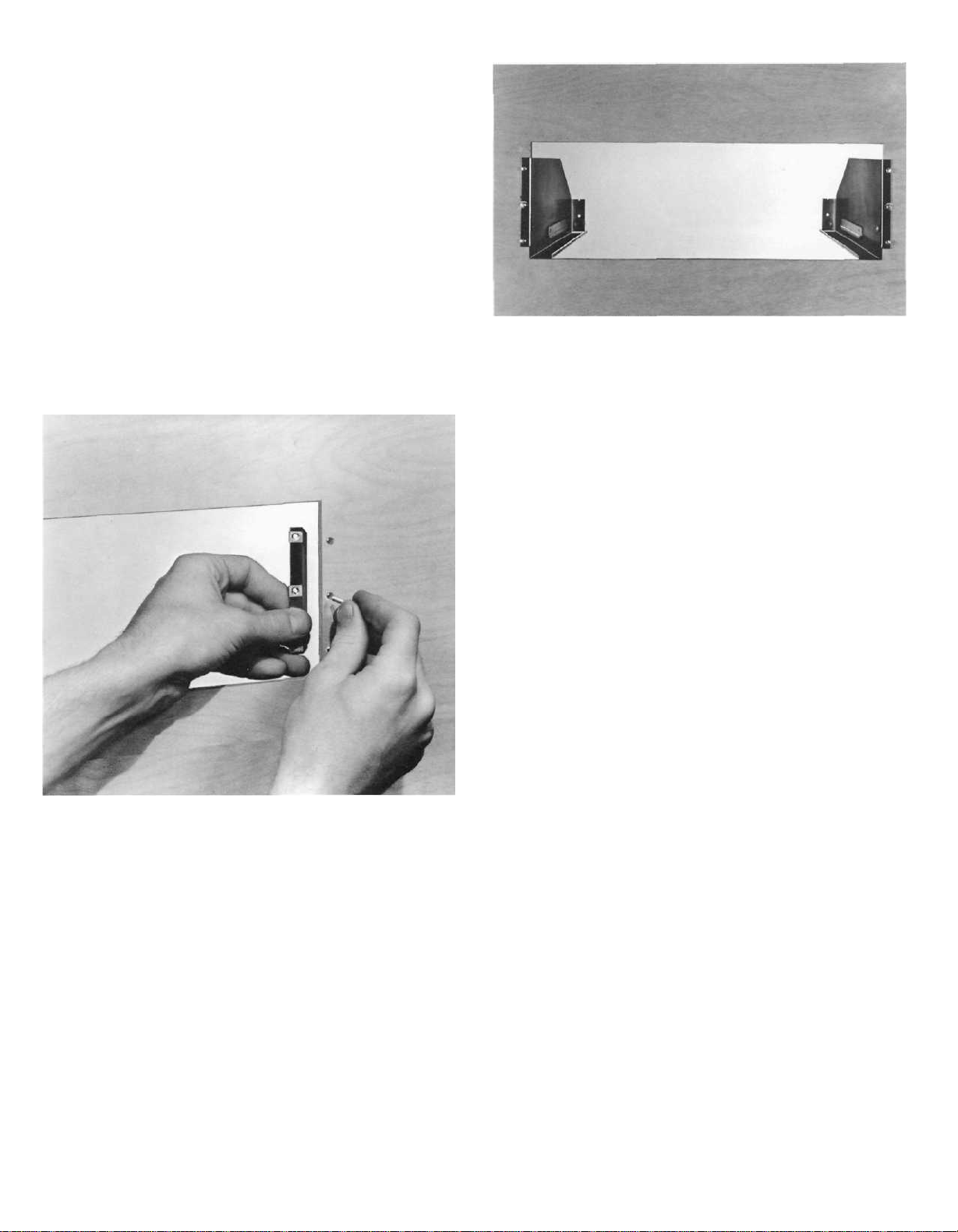
Secure the mounting strips to the rear of the cabinet
panel using two screws from the hardware package.
adjust position latches. Press the latches in and continue to slide the instrument in until the front panel is
against the cabinet panel. At the bottom front corners
of the PANLOC instruments are the PANLOC buttons.
Depressing the PANLOC buttons will lock the instrument firmly in the installation. Depressing the PANLOC
buttons a second time will release the instrument. You
can then slide the instrument forward to the inspection-
adjustment position latches will allow the instrument to
be slid completely out of the installation.
Insert the screws in the center holes of the cabinet
panel ("B" holes on the template) and tighten. The
screw head should pull into the wood slightly. (Use two
¾ inch long screws for panels under ½ inch, or two 1¼
inch long screws for panels ½ inch thick and larger.)
Attach the mounting brackets to the cabinet panel
using four screws.
Place the template over the mounting screws. The
mounting screws should be centered in the "A" and
"B" holes on the template. The sides of the mounting
brackets should match the vertical dash lines on the
template. If necessary, loosen the screws and push the
brackets into alignment and retighten.
Insert the power cord through the opening. Carefully
slide the MR 77 into the opening so the rails on the bottom of the equipment slide in the track of the mounting
brackets. Slide the instrument in until it stops at the
3
 Loading...