

McIntosh MR-74 Owners manual
THE McINTOSH MR 74 SOLID STATE AM FM/FM STEREO TUNER
READING TIME: 28 Minutes
Price $1.25


Your MR 74 AM FM/FM STEREO
TUNER will give you many years
of pleasant and satisfactory
performance. If you have any
questions please contact:
CUSTOMER SERVICE
Mclntosh Laboratory Inc.
2 Chambers Street
Binghamton, New York 13903
Phone: 607-723-3512
WARNING: TO PREVENT FIRE OR
SHOCK HAZARD, DO NOT EXPOSE
THIS UNIT TO RAIN OR MOISTURE.
Take Advantage of 3 years
of FREE Factory Service ...
Fill in the Application NOW.
CONTENTS
SERVICE CONTRACT 1
INSTALLATION 2, 3
HOW TO CONNECT 4,5
BACK PANEL INFORMATION 6
FRONT PANEL INFORMATION 6, 7
LISTENING TO THE MR 74 8
PERFORMANCE LIMITS AND RATINGS 9
PERFORMANCE CHARTS 10, 11
TECHNICAL DESCRIPTION 12, 13, 14
BLOCK DIAGRAM 15
FM STATION LOG 16
THREE YEAR FACTORY SERVICE CONTRACT
An application for a FREE THREE YEAR FACTORY SERVICE CONTRACT is included with this manual
The terms of the contract are:
1. Mclntosh will provide all parts, materials and
labor needed to return the measured performance of the instrument to the original performance limits free of any charge. The
SERVICE CONTRACT does not cover any ship-
ping costs to and from the authorized service
agency or the factory.
2. Any Mclntosh authorized service agency will
repair all Mclntosh instruments at normal
service rates. To receive the free service under
the terms of the SERVICE CONTRACT, the
SERVICE CONTRACT CERTIFICATE must accompany the instrument when taken to the
service agency.
3. Always have service done by a Mclntosh
authorized service agency. If the instrument
is modified or damaged, as a result of unauthorized repair the SERVICE CONTRACT
will be cancelled. Damage by improper use
or mishandling is not covered by the SERV-
ICE CONTRACT.
4. The SERVICE CONTRACT is issued to you as
the original purchaser. To protect you from
misrepresentation this contract cannot be
transferred to a second owner.
5. For your protection Mclntosh selects only
dealers who have technical competence to
guide purchasors fairly, and provide service
when necessary. To receive the SERVICE
CONTRACT your purchase must be made
from a Mclntosh franchised dealer.
6. Your completely filled in application for a
SERVICE CONTRACT must be postmarked
within 30 days of the date of purchase of
the instrument.
7. To receive the SERVICE CONTRACT all information on the application must be filled
in. The SERVICE CONTRACT will be issued
when the completely filled in application
is received at Mclntosh Laboratory Incor-
porated in Binghamton, New York.
Copyright © 1972 By McIntosh Laboratory Inc.
1
It is recommended that the MR 74 tuner be mounted in a normal or horizontal position. However, with
adequate ventilation the tuner can be mounted in
any position.
Adequate ventilation extends the trouble-free life
of electronic instruments. It is generally found that
each 18° F rise in operating temperature reduces the
life of electrical insulation by one half. Adequate
ventilation is an inexpensive and effective means of
preventing insulation breakdown that results from
unnecessarily high operating temperatures. The
direct benefits of adequate ventilation is longer,
trouble-free life.
The MR 74 tuner requires a mounting space that is
at least 15 inches deep, 17½ inches wide and 6
inches high. Provide additional space for the air flow
across the bottom of the tuner and a means for warm
air to escape at the top.
Remove the tuner, shelf brackets, parts bag and
mounting template from the carton. Remove tuner
from the plastic bag and place the tuner upside
down on the shipping pallet, then remove the four
plastic feet fastened to the bottom of the chassis.
The installation may be accomplished in six steps:
1. POSITION TEMPLATE AND MARK
Position the plastic mounting template over the
area of the cabinet panel where the MR 74 is to
installed. Be sure that the edges of the template
clear any shelves, partitions or existing equip-
ment located behind the panel. With the template in place mark the six "A" and "B" holes
and four small holes locating the corners of the
cutout. Next, join the four corner marks with
pencil lines; the edge of the template may be
used as a straight edge.
2. DRILL HOLES
Holding a drill perpendicularly to the panel, drill
the six "A" and "B" holes using a 3/16 inch drill.
THE SIX HOLES MUST BE DRILLED BEFORE
MAKING THE CUTOUT.
3. SAW CUTOUT
Using a saw carefully cut the rectangular opening on the inside of the pencil lines.
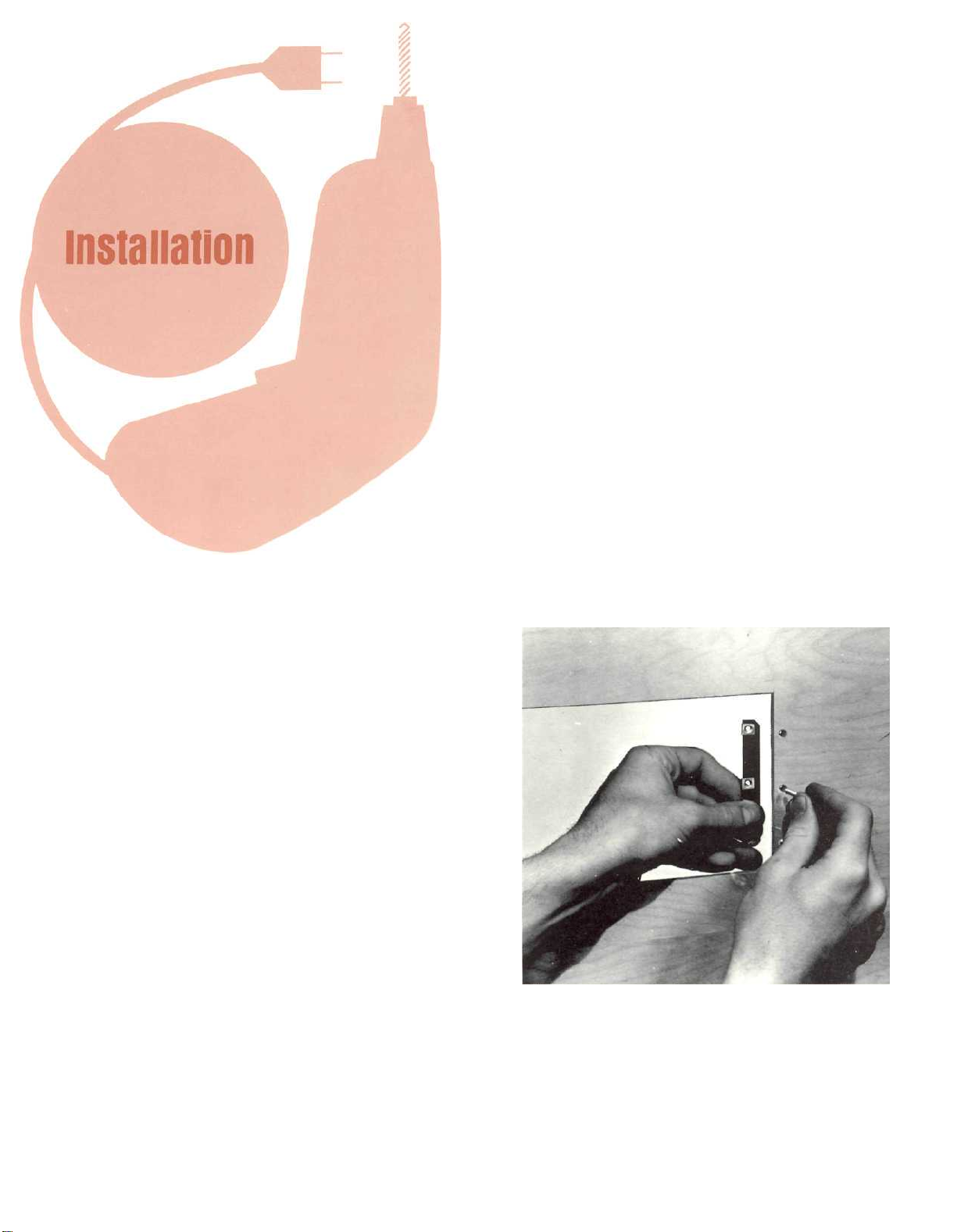
4. SECURE MOUNTING STRIPS
Secure mounting strips (supplied in the hardware package) on the inside of the cabinet
panel.
Insert two screws (supplied in the hardware
package) into the center holes ("B" holes on the
template). Use the ¾-inch long screws for
panels under ½-inch thick or 1¼-inch screws
for panels ½-inch thick or over. Place a mount-
ing strip on the back of the cabinet pane! as
shown. Align it with the three holes in the panel
and tighten the screw. The screw head should
pull slightly into the wood panel. Attach the other
mounting strip by repeating the procedure.
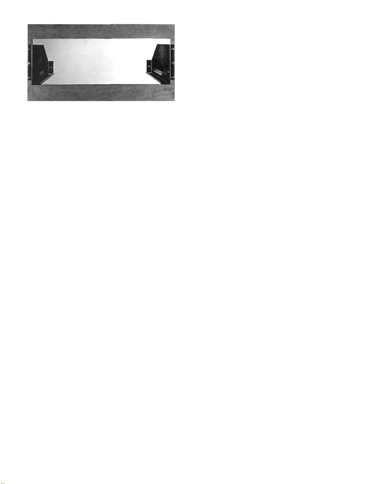
5. MOUNT PANLOC SHELF BRACKETS
Attach the Panloc shelf brackets to the cabinet
panel using four screws of the proper length.
Place the template over the mounting screws.
The screws should be centered on the "A" and
"B" holes in the template. If necessary, loosen
the screws and push the mounting brackets into
alignment then retighten.
2
6. INSTALL THE UNIT
Thread the power cord through the opening on
the cabinet panel. Carefully slide the instrument
into the opening so the rails on the bottom engage the track on the mounting brackets. Slide
the instrument in until it stops at the adjust position latches. Press the latches in and continue
to slide the instrument until its front panel is
flush with the cabinet panel. At the bottom front
corners of the instrument are the PANLOC but-
tons. Depressing the PANLOC buttons will lock
the instrument firmly in the cabinet. Depressing the PANLOC buttons a second time will
release the instrument. You can then slide the
instrument forward to the adjust position. De-
pressing the adjust position latches will allow the
instrument to be removed from the cabinet.
3

How to Connect
AUDIO OUTPUTS
Use the FIXED OUTPUT jacks to connect to a stereo
control preamplifier or other equipment which has
its own volume control. The VOLUME CONTROL
does not affect the output of the tuner at the FIXED
OUTPUT jacks.
The output impedance at the FIXED OUTPUTS is
600 ohms. Longer cables than are normally supplied
can be used to interconnect the MR 74 with other
equipment. The length of the cable is limited by the
capacity of the cable. The total capacity must not
exceed 1600 pF. For instance: cables with a capacity
of 32 pF per foot may be 50 feet long; 16 pF per foot
cable may be 100 feet long.
Use the FRONT PANEL CONTROLLED jacks to
connect to equipment such as power amplifiers or
tape recorders where control of volume at the tuner
is desired. The load impedance connected to FRONT
PANEL CONTROLLED jacks should not be less than
10,000 ohms. There is no difference in the signal
quality or maximum output levels available at either
pair of output jacks.
CONNECTING AN FM ANTENNA
One of three antenna systems can be used: (1) an
outdoor FM antenna, (2) an all channel (UHF-VHFTV) antenna, or (3) the indoor dipole supplied with
the MR 74.
An outdoor antenna is recommended for optimum
performance in all areas. In fringe areas, best results will be obtained with a highly directional FM
antenna used in conjunction with a rotator. Rotate
the antenna until the best reception is obtained. Connect the 300 ohm antenna to the 300 ANT (red)
terminals.
An UHF-VHF-TV antenna is often effective but the
antenna must be designed for both FM and TV reception. Connect the leads from the UHF-VHF-TV
antenna to the 300 ANT (red) terminals.
CONNECTING AN INDOOR DIPOLE ANTENNA
The flexible folded dipole antenna (300 ohm) is for
use in urban or high strength signal areas.
Connect the two leads from the dipole to the 300
ANT (red) terminals. The flexibility of the thin flat
wire assembly permits it to be placed under a rug,
tacked behind the stereo ... or, placed in any other
convenient location. In some cases, it may be necessary to "position" the antenna for best signal reception. This should be done before it is permanently
located. Avoid locating this antenna next to other
wires or metal objects. This antenna may not prove
effective in houses having metal siding or metal-clad
insulation.
AM ANTENNA
A high-quality loop-stick antenna is provided. It
can be rotated through nearly 180° in all directions
for maximum performance, optimum signal reception
or minimum interference. With this mobility you will
not suffer loss of sensitivity regardless of the angle
at which the instrument is mounted. A back panel
antenna jack is provided for connecting an external
antenna if desired.
CONNECTING AN AM OUTDOOR ANTENNA
For best long distance AM reception, use a copper
antenna wire 50 to 150 feet in length. Suspend the
wire in a straight line as high as possible. Attach the
wire at each end with suitable glass or ceramic insulators. Connect a lead-in wire at any convenient
point on the antenna. It is recommended that a lightning arrester be used with an outdoor AM antenna.
The arrester should be well grounded to a suitable
water pipe or a ground rod sunk into the ground.
Connect the lead-in wire to the AM ANT push connector on the antenna terminal strip on the back
panel. Set the AM ANT slide switch to EXT position.
4
 Loading...