

McIntosh MR-73 Owners manual
SOLID STATE
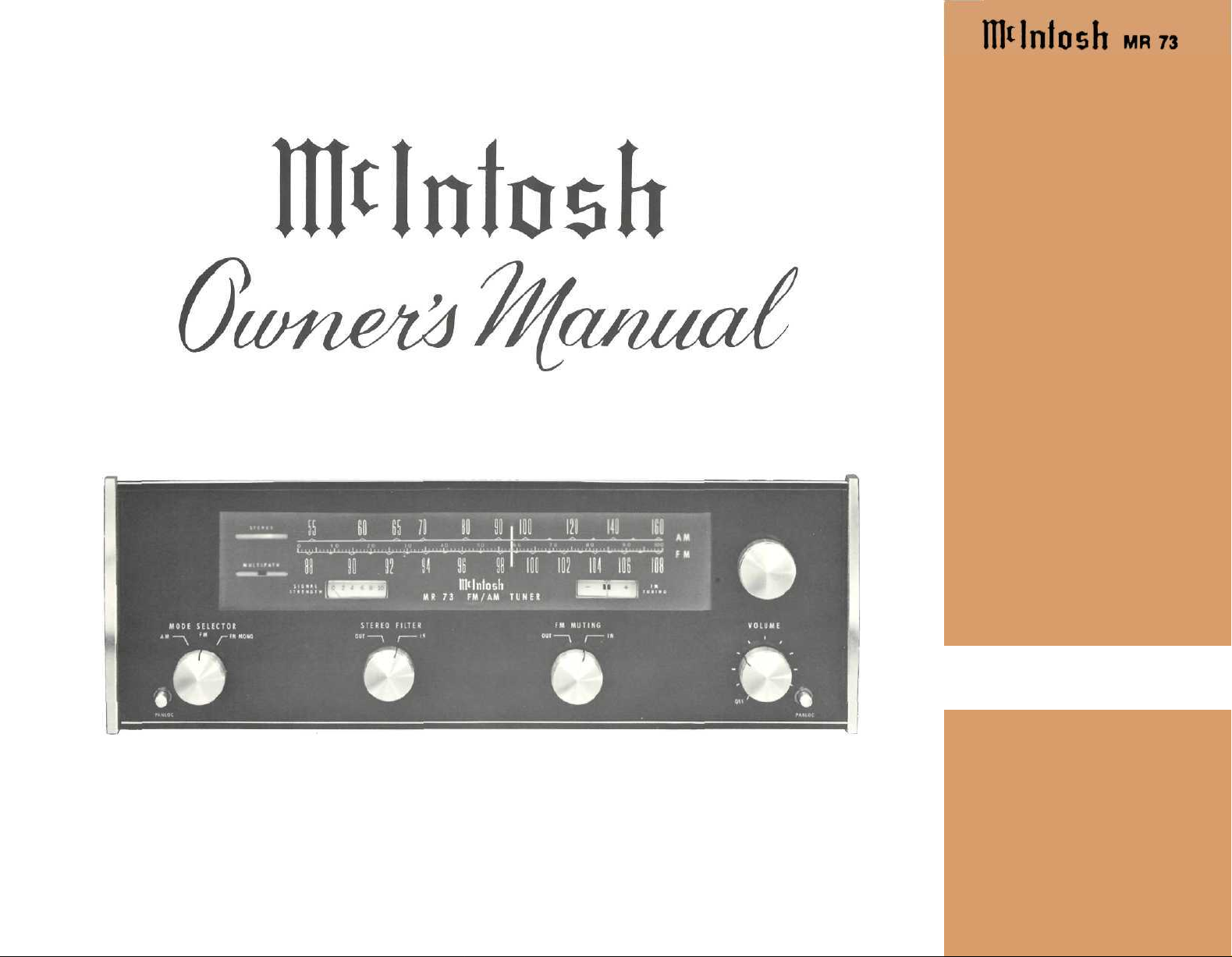
FM-AM TUNER
MR 73
PRICE $1.2 6
STEREO


CONTENTS
INTRODUCTION 2
TECHNICAL DESCRIPTION 2-4
IF YOU'RE IN A HURRY 5
The Mclntosh "will to perfection" requires that we probe
constantly into the unknown to bring the performance of our
electronic equipment closer to perfection than ever before.
This requires a constant and relentless search for low noise,
broad band conservative design with an ever lower distortion
factor. This is not required of ordinary equipment of average
designs. It is, for us, a costly but worthwhile scientific and
engineering effort. Our continuing research benefits our customers with the almost complete lack of obsolescence and
the most reliable equipment ever made. It also means the
lowest long-range cost to you. Nearly all of the Mclntosh
equipment ever made is still in use, or useable, though it
may have been made twenty years ago.
PERFORMANCE CHARTS 6
SPECIFICATIONS 7
INSTALLATION 8-9
FRONT PANEL INFORMATION 10-11
BACK PANEL INFORMATION 12
TYPICAL HOOKUP 13
CONNECTING 14
LISTENING 15
GUARANTEE 16
Your purchase of a Mclntosh instrument
shows that you are a careful discriminat-
ing buyer. One who is interested in quality
performance, quality engineering, quality
manufacturing, and long trouble-free
equipment life. You can protect your investment by spending a few minutes reading this owner's manual.
SOLID STATE
FM-AM TUNER
MR 73
When you bought a Mclntosh, you bought
countless hours of musical pleasure and
superior performance. Enjoy it!
1
STEREO

INTRODUCTION
TECHNICAL DESCRIPTION
The Mclntosh MR 73 is a precision engineered, highly sensitive
solid state AM-FM tuner.
The research staff of Mclntosh Laboratory, using the latest tech-
nology in solid state physics, has developed many circuit advances:
- Phase linear crystal shaped IF amplifiers
- Integrated Circuits that are the equivalent of 16 transistors,
3 zener diodes, 5 diodes, and 23 resistors
- Special multiplex (stereo) detecting circuits that eliminate
critical adjustments
- Ultrasonic muting for complete silence between stations while
tuning
- Automatic stereo-mono switching that is "clickless" and com-
pletely electronic
- Visual multipath indicator to help avoid multipath distortion
showing as a visual indicator of correct antenna direction for
minimum multipath reception.
- New D'Arsonval movement meters of increased sensitivity
which do not need zero setting adjustments.
- A new computer designed filter to reduce noise from stations
broadcasting subcarrier auxiliary music services. No other
tuner uses such a filter.
Exclusive Mclntosh PANLOC is used for installation. The PANLOC
system gives you absolute ease of installation, operation, and maintenance.
PANLOC is the first professional installation technique to be used
on stereo instruments.
In the PANLOC system a metal shelf is mounted first. The tuner
slides into position on this shelf. Depressing the front panel PANLOC buttons, locks the tuner firmly into position against the mounting panel.
Once you have enjoyed the outstanding performance of the
MR 73, you will understand why Mclntosh products have earned
their reputation as "THE BEST." Your Mclntosh MR 73 tuner will
give you years of the finest possible reception, and will be a valued
part of your home music system.
F.M. SECTION: This is divided into two separate modular sections:
A. The 100 mHz Radio Frequency {RF) Section. This section
houses the complete FM-RF front-end and part of the AM-RF circuits. A special, four section, variable tuning capacitor provides a
high degree of RF selectivity and excellent spurious response rejection. The problem of image rejection has been greatly reduced in the
RF section of the MR 73.
The two stage parallel-fed-cascode junction field effect transistor
(JFET) RF amplifier gives better sensitivity and higher gain than
conventional one-stage amplifiers. The use of JFET's helps to further
reduce the problem of front end overload in strong signal areas.
A mixer using a JFET has been designed for high sensitivity and
freedom from overload. Low temperature coefficient components
have been designed into the FM local oscillator to prevent fre-
quency drift. The frequency stability inherent in the local oscillator
makes automatic frequency control (AFC) unnecessary. The rate of
drift of the local oscillator is less than ten parts per million per
degree centigrade.
Both the FM and AM-RF front ends have been designed in the
same completely encased metal modules. This design gives protection against radiation or interference. The RF circuits of the MR 73
exceed the FCC requirements for suppression of oscillator radiation.
The MR 73 has antenna connections for either 300 ohm twin lead
transmission line or 75 ohm coaxial cable. The normal input im-
pedance of the first RF amplifier is 75 ohms. Impedance match to
300 ohms is provided by a Mclntosh designed balun transformer
which has negligible losses. Connections for a 300 ohm line are
made with new push type terminals. No tools are required. A type F
male connector is furnished for 75 ohm coaxial cable.
For greater signal transfer and lower distortion, a special matching transformer has been designed to interface the FM-RF to the
FM-IF amplifier. This matching transformer considerably enhances
the linear phase characteristics of the IF amplifier.
B. The FM-IF and Detector Section. The FM-IF and Detector de-
sign required extended engineering time and testing and uses the
latest concepts in integrated circuits and crystal filters. The FM-IF
consists of two integrated circuits and two phase linear crystal
filters. They combine to give a total gain of over 120 dB (the signal
is amplified to over 1,000,000 times its original level). The response
2

curve has a nearly flat top with linear phase characteristics. The
skirts of the response curve are very steep. The maximum width is
240 kHz at -3.0dB and 400 kHz at -60dB. The response curve is
symmetrical each side of the center frequency. The crystal filters are
permanently sealed and do not require adjusting. The IF cannot
drift nor vibrate out of adjustment.
Each of the two integrated circuits used in the FM-IF of the MR 73
contain 16 transistors, 3 zener diodes, 5 diodes and 23 resistors, all
on a single monolithic silicon chip.
The exceptionally high gain of the two integrated circuits assumes
"hard limiting" at very low levels of input signals.
A "phase" or "Foster Seeley" discriminator has been designed
to complement the integrated circuit IF section. The IF section has
exceptionally high gain and hard limiting characteristics, yet the
capture ratio is quite low. The detected output signal of the discriminator is extremely low in distortion content.
De-emphasis of the discriminator output restores the frequency
amplitude characteristics to the same level they were before trans-
mission.
C. FM Stereo Multiplex Section. Mclntosh Laboratory has de-
veloped a special detecting circuit in the multiplex section. A par-
ticular advantage of this circuit is the elimination of the critical
adjustments necessary with commonly used matrixing circuits. The
circuit detects the L-R sidebands, then automatically matrixes the
recovered information with the L + R main carrier signal. This yields
the left and right program output with maximum separation.
The 19kHz pilot signal is filtered from the composite stereo input
signal, amplified by a special limiting amplifier, doubled to the 38kHz
carrier frequency, and then amplified again by a limiting amplifier.
The composite signal minus the 19kHz pilot is combined with the
38kHz carrier signal. The new combination of signals is fed to the
special detector circuit mentioned above. Balanced full wave detectors are used to cancel the 38kHz components in the output.
The SCA (Subsidiary Communication Authorization) signal must
be removed from the composite output. This is accomplished by the
use of a new "Image Parameter" band elimination filter that has
been computer designed. The SCA filter rejects SCA signals without
impairing stereo performance.
FM muting in the MR 73 operates by detecting ultra-sonic noise
which is present when tuning between stations or when receiving
a weak station. The muting circuit can be activated or defeated by
the use of the muting switch on the front panel. The level of muting
desired can be adjusted by the muting level control on the top panel.
Varying the muting control adjusts the threshold at which the muting
takes effect.
When the 19 kHz carrier of a stereo signal is received, the auto-
matic FM stereo switching circuit activates the multiplex decoding
circuit. This lights the stereo indicator. The circuit switching is all
done electronically with no clicks. The automatic stereo switching
can be defeated by turning the mode selector switch to FM MONO.
(In this position the stereo indicator will still light to indicate the
presence of a stereo signal.) On monophonic transmissions the
stereo switching is inactive at all times, assuring a greater signal to
noise ratio. The stereo switching circuit has been designed so that
noise will not activate it.
AM SECTION:
The "state of the art" in electronic technology has been incorpo-
rated by Mclntosh into the MR 73 with the use of metal oxide silicon
field effect transistors (MOSFET's) in the AM section. An AM-RF
amplifier circuit includes a three section variable tuning capacitor
in the metal enclosed shielded module, which also houses the
FM-RF front end. The AM-RF amplifier uses a dual-insulated gate
MOSFET to obtain more overload protection against strong local
stations than can be obtained with conventional bipolar transistors.
The AM-RF mixer is also a dual-insulated gate MOSFET. The use
of MOSFET's in the RF amplifier and mixer provides the MR 73 with
very little cross modulation (spurious response) and the image rejection is very good.
Three double tuned IF transformers are used to obtain a high
degree of selectivity yet still allow good AM fidelity. A 10kHz whistle
filter has been incorporated at the output of the AM detector. Its
3

purpose is to supress hetrodyning that occurs between adjacent
AM carriers.
To increase the "pulling power" of the AM section of the MR 73,
connect an external antenna at the rear apron of the unit by using
a push connector. An internal transformer matches the external antenna to the input impedance of the AM front end. An optional highly
sensitive loop stick antenna is also provided for local or strong
stations. A switch on the back pane! selects either loopstick or
external antenna.
An AM sensitivity switch has been provided to decrease both the
gain of the RF amplifier and the noise between stations.
AUDIO PREAMPLIFIER SECTION:
An audio amplifier has been incorporated in the MR 73. It increases the audio level from the AM or FM multiplex outputs to a
level sufficient to drive a preamplifier or other accessory equipment.
The audio amplifier consists of 2 separate amplifiers, each amplifier
having three transistors. The design uses considerable negative
feedback. Negative feedback helps to achieve low distortion, wide
frequency response, and unexcelled stability. Each audio amplifier
has two low impedance outputs. One is a fixed output set at 2.5
volts. The second output is variable by the volume control on the
front panel.
The 16 volt regulator is the power heart of the MR 73. All signal
stages throughout the unit are powered from this regulator. The
16 volt regulator is very elaborate in design, using a specially se-
lected transistor and associated circuit. The regulator uses electronic filtering to insure the lowest possible background hum level,
maximum stability and extremely good regulation.
A half wave rectifier and filter, supply the DC high voltage needed
for the anode of the multipath indicator. The second power supply
is a full wave rectifier which supplies DC to the multiplex indicator
and to the voltage regulator.
By cross-coupling a small portion of one channel into the other
in the audio amplifier, the residual alternate channel information
can be cancelled, thereby further increasing the stereo channel
separation.
Also included in the audio section is a STEREO FILTER switch.
With the STEREO FILTER turned on and weak stations are being
received, stereo noise is reduced, but still allows ample stereo
listening performance.
POWER SUPPLY
Special design attention has been given to the power supply
section of the MR 73. Two separate rectifier circuits are used in
the MR 73.
4
 Loading...