MCC SMAJ4762A, SMAJ4763A, SMAJ4764A, SMAJ4754A, SMAJ4755A Datasheet
...
M C C
omponents 21201 Itasca Street Chatsworth
! "# $% ! "#
Features
•For surface mount application (flat handing surface for Accurate placement)
•3.3 thru 100 Volt Voltage Range
•High Surge Current Rating
•Higher Voltages Available
•Available on Tape and Reel
SMAJ4728
THRU
SMAJ4764
Silicon
1 Watt
Zener Diodes
Mechanical Data
•CASE: JEDEC DO-214AC molded plastic body over
passivated chip
•Terminals solderable per MIL-STD-750, Method 2026
•Polarity is indicated by cathode band.
•Maximum temperature for soldering: 260oC for 10 seconds.
•For surface mount applications with flame retardent epoxy Meeting UL94V-0
Maximum Ratings @ 25oC Unless Otherwise Specified
Peak Surge |
IS |
See Table 1 |
|
Current |
|
|
|
Maximum |
VF |
1.2V |
(Note: 1) |
Forward |
|
|
|
Voltage |
|
|
|
Steady State |
P(AV) |
1.0W |
(Note: 2,3) |
Power |
|
|
|
Dissipation |
|
|
|
Operation And |
TJ, TSTG |
-55oC to |
|
Storage |
|
+150oC |
|
Temperature |
|
|
|
|
|
|
|
*
NOTES:
1.Forward Current @ 200mA.
2.Mounted on 4.0mm2 copper pads to each terminal.
3.Lead temperature at 100oC or less. Derate linearly above 100oC to zero power at 150oC.
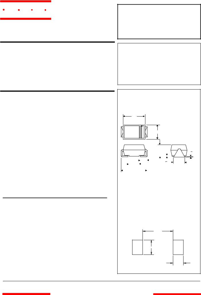
DO-214AC
(SMAJ) (High Profile)
H
 Cathode Band
J
|
|
|
|
|
|
|
|
|
|
|
|
|
|
|
|
|
|
A |
|
|
|
|
|
|
|
|
|
C |
||
|
|
|
|
|
|
|
|
|
|
|
|
|
|
|
|
|
|
|
|
|
|
|
|
|
|
|
|
|
||
|
|
|
|
|
|
|
|
|
|
|
|
|
|
|
|
|
|
|
|
|
|
|
|
|
|
|
|
|
|
|
|
|
|
|
|
|
|
|
|
|
|
|
|
|
|
|
|
|
|
|
|
|
|
|
|
|
|
|
|
|
|
|
|
|
|
|
|
|
|
|
|
|
|
|
|
|
|
|
|
|
|
|
|
|
|
|
|
|
|
|
|
|
|
|
|
|
|
|
|
|
|
|
|
E |
|
|
|
|
|
|
D |
|
|
|
|
|
B |
|
|
|
|
||
|
|
|
|
|
F |
|
|
|
|
|
|
|
|
|
|
|
|
|
|
|
|
|
||||||||
|
|
|
|
|
|
|
|
|
|
|
|
|
|
|
|
|
|
|
|
|
|
|
|
|||||||
|
|
|
|
|
|
|
|
|
|
|
|
|
|
|
|
|
|
|
|
|
|
|
|
|
|
|
||||
|
|
|
|
|
|
|
|
|
|
|
|
|
|
|
|
|
|
|
|
|
|
|
|
|
||||||
|
|
|
|
|
G |
|
|
|
|
|
|
|
|
|
|
|
|
|
|
|
|
|
|
|
|
|
|
|
||
|
|
|
|
|
|
|
|
|
|
|
|
|
|
|
|
|
|
|
|
|
|
|
|
|
|
|
|
|||
|
|
|
|
|
|
|
|
|
|
|
|
|
|
|
DIMENSIONS |
|
|
|
|
|
|
|
|
|
|
|
||||
|
|
|
|
|
INCHES |
|
|
|
|
|
|
|
|
MM |
|
|
|
|
|
|
|
|
|
|
|
|||||
|
DIM |
|
|
|
MIN |
|
MAX |
|
|
|
MIN |
|
|
|
|
MAX |
|
NOTE |
|
|||||||||||
|
A |
|
.078 |
|
|
.116 |
|
1.98 |
|
2.95 |
|
|
|
|
|
|
||||||||||||||
|
B |
|
.067 |
|
|
.089 |
|
1.70 |
|
2.25 |
|
|
|
|
|
|
||||||||||||||
|
C |
|
.002 |
|
|
.008 |
|
.05 |
|
.20 |
|
|
|
|
|
|
||||||||||||||
|
D |
|
--- |
|
|
|
.02 |
|
--- |
|
.51 |
|
|
|
|
|
|
|||||||||||||
|
E |
|
.035 |
|
|
.055 |
|
.89 |
|
1.40 |
|
|
|
|
|
|
||||||||||||||
|
F |
|
.065 |
|
|
.096 |
|
1.65 |
|
2.45 |
|
|
|
|
|
|
||||||||||||||
|
G |
|
.205 |
|
|
.224 |
|
5.21 |
|
5.69 |
|
|
|
|
|
|
||||||||||||||
|
H |
|
.160 |
|
|
.180 |
|
4.06 |
|
4.57 |
|
|
|
|
|
|
||||||||||||||
|
J |
|
.100 |
|
|
.112 |
|
2.57 |
|
2.84 |
|
|
|
|
|
|
||||||||||||||
SUGGESTED SOLDER
PAD LAYOUT
0.090”
0.085”
0.070”
www.mccsemi.com
 Loading...