


Maytag MHW7100DW, WFW8740DW, WFW72HEDW, MHW4200BW, WFW97HEDC Installation Instructions
...WASHER INSTALLATION |
INSTRUCTIONS |
INSTRUCTIONS |
D’INSTALLATION |
|
DE LA LAVEUSE |
Table of Contents |
|
WASHER SAFETY.......................................................... |
1 |
INSTALLATION REQUIREMENTS................................ |
2 |
Tools and Parts................................................................ |
2 |
Location Requirements................................................... |
3 |
Drain System.................................................................... |
4 |
Electrical Requirements.................................................. |
5 |
INSTALLATION INSTRUCTIONS.................................. |
5 |
Connect Drain Hose........................................................ |
6 |
Connect Inlet Hoses........................................................ |
7 |
Level Washer.................................................................... |
8 |
Complete Installation Checklist..................................... |
9 |
Table des matières |
|
SÉCURITÉ DE LA LAVEUSE....................................... |
10 |
EXIGENCES D’INSTALLATION................................... |
11 |
Outillage et pièces......................................................... |
10 |
Exigences d’emplacement............................................ |
12 |
Système de vidange...................................................... |
14 |
Spécifications électriques............................................. |
14 |
INSTRUCTIONS D’INSTALLATION............................. |
15 |
Raccordement du tuyau de vidange............................ |
16 |
Raccordement des tuyaux d’arrivée d’eau.................. |
17 |
Établissement de l’aplomb de la laveuse.................... |
19 |
Liste de vérification pour l’achèvement |
|
de l’installation............................................................... |
20 |
Para obtener acceso al instrucciones de instalación en español, o para obtener información adicional acerca de su producto, visite: www.whirlpool.com
INSTALLATION NOTES |
NOTES SUR L’INSTALLATION |
Date of purchase:_________________________________ |
Date d’achat :____________________________________ |
Date of installation:_ _______________________________ |
Date d’installation :_ _______________________________ |
Installer:_________________________________________ |
Installateur :______________________________________ |
Model number:____________________________________ |
Numéro de modèle :________________________________ |
Serial number:____________________________________ |
Numéro de série :__________________________________ |
WASHER SAFETY
W10631155A |
W10631156A-SP |
INSTALLATION REQUIREMENTS
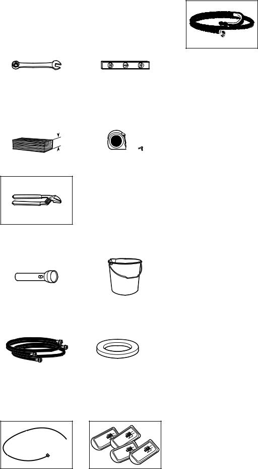
TOOLS AND PARTS
Gather required tools and parts before starting installation.
Tools needed:
|
|
|
|
|
|
|
|
|
Adjustable or open end |
|
Level |
||||||
wrenches 1/2" (13 mm) |
|
|
|
|
|
|
||
and 9/16" (14 mm) |
|
|
|
|
|
|
||
|
|
|
|
|
|
|
|
|
4" min |
|
|
|
|
|
|
|
|
(102 mm) |
|
|
|
|
|
|
|
|
|
|
|
|
|
|
|
||
|
|
|
|
|
|
|
|
|
|
|
|
|
|
|
|
|
|
|
|
|
|
|
|
|
|
|
Wood block
Pliers that open to 19⁄16" (39.5 mm)
Optional tools:
Ruler or measuring tape
|
|
|
Flashlight |
|
Bucket |
Parts needed: (Not supplied with washer)
|
|
|
Water inlet hoses (2) |
|
Flat inlet hose washers (4) |
Parts supplied:
NOTE: All parts supplied for installation are in the washer basket.
Drain hose with clamp and form (may be shipped unassembled)
Available Accessories:
An optional matching pedestal is available for your washer. Please contact your retailer for ordering information, or see the “Assistance or Service” page on the back of your “Use and Care Guide”.
Alternate parts: (Not supplied with washer)
Your installation may require additional parts. To order, please refer to toll-free numbers on the back page of your “Use and Care Guide”.
If you have: |
You will need: |
Overhead sewer |
Standard 20 gal. (76 L) 39" (990 mm) |
|
tall drain tub or utility sink, sump |
|
pump and connectors (available from |
|
local plumbing suppliers) |
1" (25 mm) standpipe |
2" (51 mm) diameter to 1" (25 mm) |
|
diameter Standpipe Adapter |
|
Part Number 3363920 |
|
Connector Kit Part Number 285835 |
Drain hose too short |
Extension Drain Hose Part |
|
Number 285863 |
|
Connector Kit Part Number 285835 |
Lint clogged drain |
Drain Protector Part Number 367031 |
|
Connector Kit Part Number 285835 |
Floor drain system |
Siphon Break Kit Part Number 285834 |
|
Connector Kit (x2) Part Number 285835 |
|
Extension Drain Hose Part |
|
Number 285863 |
Alternate Inlet Hoses: (may be required for some installations, not supplied with washer)
n8212656RP 10 ft. (3.0 m) Inlet hose, Black EPDM (2 pack)
n8212641RP 5 ft. (1.5 m) Inlet hose, Black EPDM (2 pack)
n8212546RP 4 ft. (1.2 m) Inlet hose, Black EPDM (2 pack)
n8212545RP 5 ft. (1.5 m) Inlet hose, Red and Blue EPDM
(2 pack)
n8212487RP 5 ft. (1.5 m) Nylon braided inlet hose (2 pack)
n8212638RP 6 ft. (1.8 m) Nylon braided inlet hose, space
saving 90° elbow, hypro-blue steel couplings (2 pack)
n 8212637RP 6 ft. (1.8 m) Inlet hose, Black EPDM, space saving 90° elbow, hypro-blue steel couplings (2 pack)
Cable tie |
Transport bolt hole |
|
plugs (4) |
2
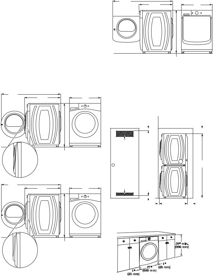
LOCATION REQUIREMENTS
Proper installation is your responsibility.
You will need:
nA water heater set to 120° F (49° C).
nA grounded electrical outlet located within 6 ft (1.8 m) of power cord on back of washer.
nHot and cold water faucets located within 4 ft (1.2 m) of hot and cold water fill valves on washer, and water pressure of 20-100 psi (137.9-689.6 kPa).
nA level floor with maximum slope of 1" (25 mm) under entire washer. Installing on carpet or surfaces with foam backing is not recommended.
nFloor must support washer’s total weight (with water and load) of 315 lbs (143 kgs).
IMPORTANT: Do not install, store or operate washer where it will be exposed to weather or in temperatures below 32° F (0° C). Water remaining in washer after use may cause damage in low temperatures. See “Washer Care” in your “Use and Care Guide” for winterizing information.
Whirlpool Models*
523/4" |
|
|
(1340 mm) |
335/16" |
27" |
|
(846 mm) |
(686 mm) |
|
|
383/4" - 393/4" |
|
|
(948 mm - 1010 mm) |
523/4" |
|
|
(1340 mm) |
331/8" |
27" |
|
(841 mm) |
(686 mm) |
|
|
383/4" - 393/4" |
|
|
(948 mm - 1010 mm) |
*For additional details (or information) specific to your model, refer to the Dimension Guide at www.whirlpool.com.
Maytag Models
5215/16" |
|
|
(1345 mm) |
3215/16" |
27" |
|
(837 mm) |
(686 mm) |
|
|
383/4" - 393/4" |
|
|
(948 mm - 1010 mm) |
All dimensions show recommended spacing allowed, except for closet door ventilation openings which are the minimum required.
For each arrangement, consider allowing more space for ease of installation and servicing, and spacing for companion appliances and clearances for walls, doors, and floor moldings.
Space must be large enough to allow door to fully open. Add spacing of 1" (25 mm) on all sides of washer to reduce
noise transfer. If a closet door or louvered door is installed, top and bottom air openings in door are required.
Recessed area or closet installation (stacked washer and dryer):
3" |
|
|
|
|
6" |
||
(76 mm) |
(152 mm) |
||||||
|
|
|
|
|
|
|
|
|
|
|
|
|
|
|
|
|
|
|
|
|
|
|
|
|
|
|
|
|
|
|
|
|
|
|
|
|
|
|
|
48 in.2
(310 cm2)
761/2"
(1943 mm)
24 in.2
(155 cm2)
|
|
|
|
|
|
|
|
|
|
|
|
|
|
|
|
|
|
|
|
|
|
|
1"* |
|
|
|
|
|
|
||
|
|
|
|
|
|
|
|
|
|
|
|
|
|||
|
|
|
|
|
|
|
|
|
|
|
|
||||
3" |
|
|
|
|
|
|
|
|
5" |
|
|||||
|
|
|
|
||||||||||||
(76 mm) |
|
(25 mm) |
|
(127 mm) |
|||||||||||
* Add spacing of 1" (25 mm) on all sides of washer/dryer.
Custom under counter installation:
3
Recessed area or closet installation (washer only): |
Custom cabinet installation: |
3" |
|
|
|
|
(76 mm) |
|
|
|
7" |
|
|
|
|
(178 mm) |
48 in.2 |
|
|
|
|
(310 cm2) |
|
|
|
|
|
|
|
14" |
|
|
|
|
(356 mm) |
|
24 in.2 |
|
|
|
|
(155 cm2) |
|
|
|
|
3" |
1" * |
4" ** |
1" * |
4" ** |
(76 mm) |
(25 mm) |
(102 mm) |
(25 mm) |
(102 mm) |
* Add spacing of 1" (25 mm) on all sides of washer.
** Recommended 4" (102 mm), minimum 1.5" (38 mm)
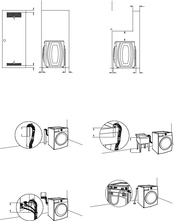
DRAIN SYSTEM
Drain system can be installed using a floor drain, wall standpipe, floor standpipe, or laundry tub. Select method you need.
IMPORTANT: To avoid siphoning, only 4.5" (114 mm) of drain hose should be inside standpipe. Always secure drain hose with cable tie.
Floor standpipe drain system
4.5"  (114 mm)
Minimum diameter for a standpipe drain: 2" (51 mm). Minimum carry-away capacity: 17 gal. (64 L) per minute. A 1/4" (6 mm) diameter to 1" (25 mm) diameter Standpipe Adapter Kit is available (Part Number 3363920). Top of standpipe must be at least 30" (762 mm) high; install no higher than 96" (2.44 m) from bottom of washer. If you have an overhead sewer and need to pump higher than 96" (2.44 m), a sump pump and associated hardware are needed. See “Alternate Parts”.
Wall standpipe drain system
4.5" (114 mm)
See requirements for floor standpipe drain system.
Laundry tub drain system
4.5" (114 mm)
min.
30"
(762 mm)
Minimum capacity: 20 gal. (76 L). Top of laundry tub must be at least 30" (762 mm) above floor; install no higher than 96" (2.44 m) from bottom of washer.
Floor drain system
Floor drain system requires a Siphon Break Kit (Part Number 285834), 2 Connector Kits (Part Number 285835), and an Extension Drain Hose (Part Number 285863) that may be purchased separately. See “Alternate Parts”. Minimum siphon break height: 28" (710 mm) from bottom of washer. (Additional hoses may be needed.)
4

ELECTRICAL REQUIREMENTS |
INSTALLATION INSTRUCTIONS |
 WARNING
Electrical Shock Hazard Plug into a grounded 3 prong outlet. Do not remove ground prong.
Do not use an adapter.
Do not use an extension cord.
Failure to follow these instructions can result in death, fire, or electrical shock.
nA 120 volt, 60 Hz., AC only, 15or 20-amp, fused electrical supply is required. A time-delay fuse or circuit breaker is recommended. It is recommended that a separate circuit breaker serving only this appliance be provided.
nThis washer is equipped with a power supply cord having a 3 prong grounding plug.
nTo minimize possible shock hazard, the cord must be plugged into a mating, 3 prong, grounding-type outlet, grounded in accordance with local codes and ordinances. If a mating outlet is not available, it is the personal responsibility and obligation of the customer to have the properly grounded outlet installed by a qualified electrician.
nIf codes permit and a separate ground wire is used, it is recommended that a qualified electrician determine that the ground path is adequate.
nDo not ground to a gas pipe.
nCheck with a qualified electrician if you are not sure the washer is properly grounded.
nDo not have a fuse in the neutral or ground circuit.
NOTE: To avoid floor damage, set washer onto cardboard before moving it.
1. Move washer
48" |
(1.2 m) |
It is necessary to remove all shipping materials for proper operation and to avoid excessive noise from washer.
Move washer to within 4 ft (1.2 m) of its final location. It must be in a fully upright position.
2. Locate transport bolts
Locate four transport bolts on rear of washer.
5
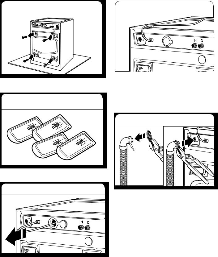
3. Remove transport bolts from |
|
|
6. Place power cord over top |
|
washer |
|
|
|
|
|
|
|
|
|
|
|
|
|
|
|
|
|
|
|
|
|
|
|
|
Loosen bolts with a 1/2" (13 mm) wrench. Slide each bolt and spacer to center of hole. Pull bolts and plastic spacers from back of washer. Discard bolts and spacers.
4. Cover bolt holes with transport bolt hole plugs
Close bolt holes on cabinet back with four transport bolt hole plugs included with washer parts.
5. Remove power cord
Remove the yellow shipping strap from the cord. Gently place power cord over top of washer to allow free access to back of washer.
IMPORTANT: Do not plug washer in until installation has been completed.
CONNECT DRAIN HOSE
7. Attach drain hose to drain port
Ribs |
If clamp is not already in place on elbow end of drain hose, squeeze clamp with pliers and slide it over end of hose, centering it between the ribs, as shown. Squeeze clamp with pliers and slide elbow end of drain hose onto drain port and secure with clamp.
For a laundry tub or standpipe drain, go to step 9.
For a floor drain, remove the preinstalled drain hose form as shown in Step 8. You may need additional parts with separate directions. See “Alternate Parts”.
Pull power cord through opening in rear panel and close hole with attached cap.
NOTE: If washer is transported at later date, call your local service center to avoid suspension and structural damage, a certified technician must properly set up washer for relocation.
6
 Loading...