


Maytag MLE20PNAGW, MLE20PNBGW, MLG20PDBGW, MLE20PNCGW, MLE20PDCGW Installation Instructions
...INSTALLATION
INSTRUCTIONS
Commercial Stacked
Washer/Dryer
Gas or Electric
INSTRUCTIONS D’INSTALLATION
Lave-linge/sèche-linge superposés à usage commercial
À gaz ou électrique
INSTRUCCIONES DE INSTALACIÓN
Lavadora/Secadora comerciales apiladas A gas o eléctricas
ISTRUZIONI
D’INSTALLAZIONE
Lavatrice/asciugatrice commerciale a colonna A gas o elettrica
MLE20PD
MLG20PD
MLE20PN
W10335466C |
www.maytagcommerciallaundry.com |
|
TABLE OF CONTENTS
(Australia and New Zealand Installations)
. |
Page |
Stacked Washer/Dryer Safety.................................................................. |
3 |
Stacked Washer/Dryer Disposal............................................................. |
6 |
Tools & Parts ..................................................................................................... |
7 |
Alternate Parts and Accessories............................................................. |
8 |
Dimensions/Clearances ............................................................................. |
9 |
Stacked Washer/Gas Dryer Installation Requirements .......... |
10 |
Stacked Washer/Electric Dryer |
|
Installation Requirements ........................................................................ |
13 |
Dryer Venting Requirements .................................................................. |
15 |
Dryer Gas Supply Requirements .......................................................... |
17 |
Installing Stacked Washer/Dryer......................................................... |
18 |
Washer Drain System ................................................................................. |
21 |
Leveling .............................................................................................................. |
22 |
Complete Installation ................................................................................. |
23 |
Reversing Dryer Door Swing .................................................................. |
24 |
Stacked Washer/Dryer Maintenance Instructions ...................... |
26 |
If You Need Assistance ............................................................................. |
27 |
Technical Specifications – Gas Dryer ................................................ |
28 |
Electronic Control Setup Instructions ................................................ |
29 |
Warranty ............................................................................................................ |
35 |
TABLE DES MATIÈRES
. |
Page |
Sécurité du lave-linge/sèche-linge superposés............................ |
36 |
Élimination du lave-linge/sèche-linge superposés...................... |
39 |
Outils et pièces ............................................................................................... |
40 |
Pièces supplémentaires et accessoires ............................................ |
41 |
Dimensions/Distances de dégagement ........................................... |
42 |
Exigences d’installation pour |
|
le lave-linge/sèche-linge à gaz superposés.................................... |
43 |
Exigences d’installation pour le lave-linge/sèche-linge |
|
électriques superposés ............................................................................ |
46 |
Exigences concernant l’évacuation du sèche-linge .................... |
48 |
Spécifications de l’alimentation en gaz du sèche-linge ........... |
51 |
Installation du lave-linge/sèche-linge superposés ..................... |
52 |
Système d’évacuation du lave-linge..................................................... |
55 |
Nivellement ........................................................................................................ |
56 |
Achever l’installation ..................................................................................... |
57 |
Inversion du sens d’ouverture de la porte du sèche-linge ....... |
58 |
Instructions d’entretien du lave-linge/ |
|
sèche-linge superposés ............................................................................ |
60 |
Si vous avez besoin d’assistance .......................................................... |
61 |
Fiche technique – sèche-linge à gaz ................................................... |
62 |
Instructions de réglage du tableau |
|
de commande électronique ..................................................................... |
63 |
Garantie .............................................................................................................. |
70 |
ÍNDICE
. |
Página |
Seguridad de la lavadora/secadora apiladas................................. |
71 |
Eliminación de la lavadora/secadora apiladas............................... |
74 |
Herramientas y piezas................................................................................. |
75 |
Piezas y accesorios adicionales ............................................................ |
76 |
Dimensiones y espacios libres .............................................................. |
77 |
Requisitos de instalación de la lavadora/secadora |
|
a gas apiladas ................................................................................................. |
78 |
Requisitos de instalación de la lavadora/ |
|
secadora eléctricas apiladas ................................................................... |
81 |
Requisitos de ventilación de la secadora ......................................... |
83 |
Requisitos del suministro de gas de la secadora ........................ |
86 |
Instalación de la lavadora/secadora apiladas................................ |
87 |
Sistema de desagüe de la lavadora..................................................... |
90 |
Nivelación ........................................................................................................... |
91 |
Complete la instalación .............................................................................. |
92 |
Cómo invertir el cierre de la puerta de la secadora ..................... |
93 |
Instrucciones de mantenimiento |
|
de la lavadora/secadora apiladas ......................................................... |
95 |
Si necesita ayuda ........................................................................................... |
96 |
Especificaciones técnicas – secadora a gas .................................. |
97 |
Instrucciones de programación del control electrónico ........... |
98 |
Garantía ........................................................................................................... |
105 |
INDICE
. |
Pagina |
Sicurezza della lavatrice/asciugatrice impilati........................... |
106 |
L’eliminazione della lavatrice/asciugatrice impilati.................. |
109 |
Attrezzi e componenti ............................................................................. |
110 |
Parti ed accessori alternati.................................................................... |
111 |
Dimensioni/spazi ...................................................................................... |
112 |
Requisiti dell’installazione della lavatrice/asciugatrice |
|
a gas impilati ................................................................................................ |
113 |
Requisiti dell’installazione della lavatrice/asciugatrice |
|
elettrica impilat ........................................................................................... |
116 |
Requisiti di scarico dell’asciugatrice ............................................... |
118 |
Requisiti di alimentazione del gas dell’asciugatrice ............... |
120 |
Installazione della lavatrice/asciugatrice impilati..................... |
121 |
Sistema dello scolo della lavatrice .................................................. |
124 |
Livellamento ................................................................................................. |
125 |
Completamento dell’installazione .................................................... |
126 |
Inversione della rotazione di apertura dell’asciugatrice ....... |
127 |
Istruzioni di manutenzione della lavatrice/ |
|
asciugatrice impilat..................................................................................... |
129 |
Se avete bisogno dell’assistenza ..................................................... |
130 |
Dati tecnici – asciugatrice a gas ........................................................ |
131 |
Configurazione dei controlli elettronici .......................................... |
132 |
Garanzia ......................................................................................................... |
139 |
2
STACKED WASHER/DRYER SAFETY
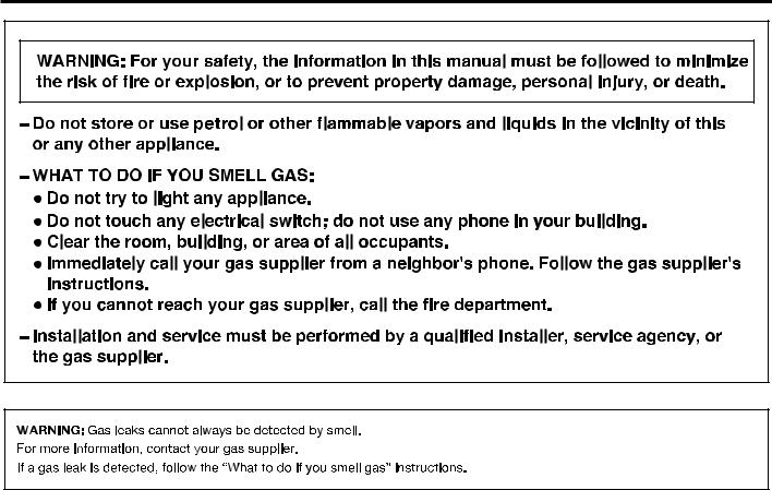
νIt is recommended that the owner post, in a prominent location, instructions for the customer’s use in the event the customer smells gas. This information should be obtained from your gas supplier.
νPost the following warning in a prominent location.
FOR YOUR SAFETY
1.DO NOT USE OR STORE PETROL OR OTHER FLAMMABLE MATERIALS IN THIS APPLIANCE OR NEAR THIS APPLIANCE.
2.DO NOT SPRAY AEROSOLS IN THE VICINITY OF THIS APPLIANCE WHILE IT IS IN OPERATION.
3.DO NOT MODIFY THIS APPLIANCE.
3
STACKED WASHER/DRYER SAFETY
4

STACKED WASHER/DRYER SAFETY
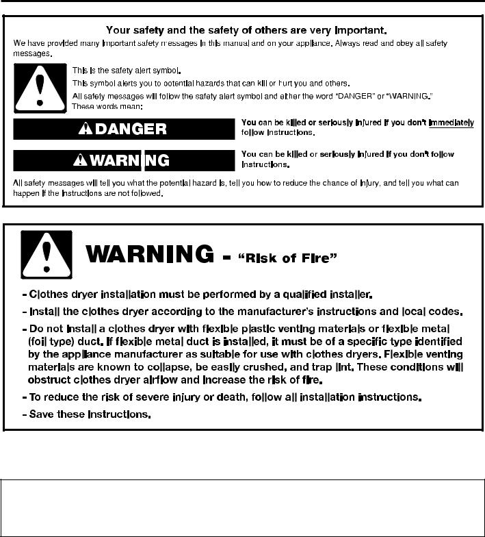
IMPORTANT SAFETY INSTRUCTIONS
WARNING: To reduce the risk of fire, electric shock, or injury to persons when using the washer/dryer, follow basic precautions, including the following:
νRead all instructions before using the washer/dryer.
νThis dryer is intended only for drying clothes and textiles that have been washed in water. Do not use for any other purpose.
νWARNING: If you smell gas, do not use the dryer or any electrical equipment nearby. Warn other people to clear the area. Contact the dryer owner immediately.
νDo not place items exposed to cooking oils in your dryer. Items contaminated with cooking oils may contribute to a chemical reaction that could cause a load to catch fire.
νIf it is unavoidable that fabrics that contain vegetable or cooking oil or that have been contaminated by hair care products be placed in a tumble dryer, they should first be washed in hot water with extra detergent – this will reduce, but not eliminate the hazard.
νDo not wash or dry articles that have been previously cleaned in, washed in, soaked in, or spotted with petrol, dry-cleaning solvents, other flammable, or explosive substances as they give off vapors that could ignite or explode.
νItems that have been soiled with substances such as acetone, alcohol, petrol, kerosene, spot removers,
turpentine, waxes, and wax removers should be washed in hot water with extra detergent before being dried in the dryer.
νDo not add gasoline, dry-cleaning solvents, or other flammable, or explosive substances to the wash water. These substances give off vapors that could ignite or explode.
νDo not dry unwashed items in the dryer.
νDo not use this dryer if industrial chemicals have been used for cleaning. The possible presence of residual quantities of aggressive or decomposed chemicals in the load may produce damage to the dryer and harmful fumes.
νDo not allow children to play on or in the washer/dryer. Close supervision of children is necessary when the washer/dryer is used near children.
νThis dryer is not intended for use by persons (including children) with reduced physical, sensory, or mental capabilities, or lack of experience or knowledge, unless they have been given supervision or instruction concerning use of the dryer by a person responsible for their safety.
νBefore the washer/dryer is removed from service or discarded, remove the doors to the washer/dryer compartments.
νDo not reach into the washer/dryer if the tub, agitator or drum is moving.
νDo not open door while dryer is in operation. It will stop.
νWhen loading or re-loading the dryer, avoid touching hot metal parts of the drum (burn risk).
νIf drum rotation is blocked due to trapped textiles, disconnect the dryer from the electrical supply before gently removing the blockage.
νIf the dryer is not heating, or appears to be defective or damaged, do not use it. Contact the owner.
νDo not install or store the washer/dryer where it will be exposed to the weather.
νDo not tamper with controls.
νClean dryer lint screen before or after each load.
νDo not use this dryer without the lint screen in place.
νUnder certain conditions, hydrogen gas may be produced in a hot water system that has not been used for 2 weeks or more. HYDROGEN GAS IS EXPLOSIVE. If the hot water system has not been used for such a period, before using the washer, turn on all hot water faucets and let the water flow from each for several minutes. This will release any accumulated hydrogen gas. As the gas is flammable, do not smoke or use an open flame during this time.
νDo not repair or replace any part of the washer/dryer or attempt any servicing unless specifically recommended in this Use and Care Guide or in published user-repair instructions that you understand and have the skills to carry out.
νDo not use fabric softeners or products to eliminate static unless recommended by the manufacturer of the fabric softener or product.
νDo not use heat to dry articles containing foam rubber or similarly textured rubber-like materials.
νThe final part of a tumble dryer cycle occurs without heat (cool-down cycle) to ensure that the articles are left at a temperature that ensures that the items will not be damaged.
νWARNING: Never stop a tumble dryer before the end
of the drying cycle unless all items are quickly removed and spread out so that the heat is dissipated. (Avoids risk of spontaneous combustion).
νIn case of electrical supply failure, remove the load quickly and spread it out to avoid risk of spontaneous combustion.
νKeep area around the exhaust opening and adjacent surrounding areas free from the accumulation of lint, dust, and dirt.
νThe fresh air ventilation openings into the room and into the dryer must not be blocked or sealed.
νEmergency stop control: The mains plug should be removed in an emergency.
νThe interior of the dryer and dryer exhaust vent should be cleaned periodically by qualified service personnel.
νSee “Electrical Requirements” section of the Installation Instructions booklet for grounding instructions.
SAVE THESE INSTRUCTIONS
5
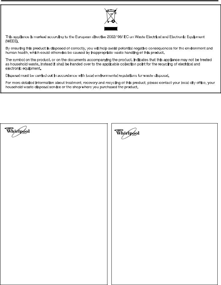
STACKED WASHER/DRYER DISPOSAL
MODEL NOMENCLATURE:
MLE – Maytag Electric |
PD – Electronic Control – Coin Drop Enabled |
MLG – Maytag Gas |
PN – Electronic Control – Non-Pay |
20 – Model Type Number |
|
EU - DECLARATION OF CONFORMITY
CE - DECLARATION DE CONFORMITE
We BAUKNECHT HAUSGERÄTE GmbH, D-73614 Schorndorf representing WHIRLPOOL EUROPE S.r.l I-21025 COMERIO
declare under our sole responsibility that the product
Commercial stacked pair |
MAYTAG |
MLE 20PD |
washer / dryer |
MAYTAG |
MLE 20PN |
to which this declaration relates is in conformity with the following standard(s) or other normative document(s)
EN 60335-1:2002+A1+A2+A11+A12+A13+A14+A15
EN 60335-2-7:2010
EN 60335-2-11:2010
EN 62233:2008
EN 61770:1999+A1:2004+A2:2006
EN ISO 10472-1:2008
EN ISO 10472-2:2008
EN ISO 14121-1:2007
EN 55014-1:2006+A1:2009
EN 55014-2:1997+A1:2001+A2:2008
EN 61000-3-2:2006+A1:2009+A2:2009
EN 61000-3-11:2000
following the provisions of Directive(s):
2006/42/EC MACHINERY DIRECTIVE
2004/108/EC ELECTROMAGNETIC COMPATIBILITY DIRECTIVE 2011/65/EU ROHS DIRECTIVE
2002/96/EC WEEE DIRECTIVE
|
represented by |
|
Schorndorf, 28.02.2012 |
Micael Zirondi |
Karl-Dieter Klingenstein |
Place and date: |
Director PDC FC EMEA |
Product Approval |
|
|
GPO, Schorndorf |
|
Name and signature of aurthorised person |
|
|
Nom et signature de la personne autorisée |
|
EU - DECLARATION OF CONFORMITY
CE - DECLARATION DE CONFORMITE
We BAUKNECHT HAUSGERÄTE GmbH, D-73614 Schorndorf representing WHIRLPOOL EUROPE S.r.l I-21025 COMERIO
declare under our sole responsibility that the product
Commercial gas dryer MAYTAG MLG 20PD
to which this declaration relates is in conformity with the following standard(s) or other normative document(s)
EN 60335-1:2002+A1+A2+A11+A12+A13 (+A14+A15 only electrical part) EN 60335-2-11:2010
EN 60335-2-102:2006+A1 EN 62233:2008
EN 12752-1:1999
EN ISO 10472-1:2008
EN ISO 10472-4:2008
EN ISO 14121-1:2007
EN 55014-1:2006+A1:2009
EN 55014-2:1997+A1:2001+A2:2008
EN 61000-3-2:2006+A1:2009+A2:2009 EN 61000-3-11:2000
following the provisions of Directive(s):
2006/42/EC MACHINERY DIRECTIVE
2009/142/EC EUROPEAN GAS APPLIANCE DIRECTIVE 2004/108/EC ELECTROMAGNETIC COMPATIBILITY DIRECTIVE 2011/65/EU ROHS DIRECTIVE
2002/96/EC WEEE DIRECTIVE
|
represented by |
|
Schorndorf, 19.04.2012 |
Micael Zirondi |
Karl-Dieter Klingenstein |
Place and date: |
Director PDC FC EMEA |
Product Approval |
|
|
GPO, Schorndorf |
|
Name and signature of aurthorised person |
|
|
Nom et signature de la personne autorisée |
|
6
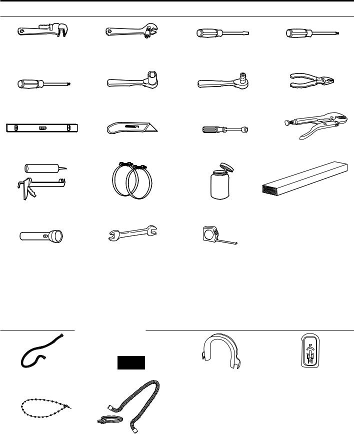
TOOLS & PARTS
Tools Needed:
203 mm (8") |
203 mm (8") or 254 mm (10") |
Flat-Blade Screwdriver |
Phillips Screwdriver |
or 254 mm (10") |
Adjustable Wrench |
|
|
Pipe Wrench |
that opens to 25 mm (1") |
|
|
Torx®† T-20 Security |
25 mm (1") Hex-Head |
8 mm (5/16") Socket Wrench |
Pliers |
Screwdriver or Bit |
Socket Wrench |
|
(that open to 39 mm [19/16"]) |
Level |
Utility Knife |
6 mm (1/4") Nut Driver |
Locking Pliers |
Caulk Gun and Caulk |
Vent Clamps |
Pipe-Joint Compound |
686 mm (27") Wood Block |
(for installing new exhaust vent) |
|
suitable for gas type |
|
Flashlight (optional) |
13 mm (1/2") and 14 mm |
Ruler or Measuring Tape |
|
(9/16") Open-End Wrenches |
|
Parts Supplied:
Water Inlet Hoses (2) |
Inlet Hose Washers (4) |
U-Shaped Hose Form |
Transit Bolt Hole Plug (4) |
Beaded Tie Strap
Drain Hose/Clamp
†® TORX is a registered trademark of Saturn Fasteners, Inc.
7

ALTERNATE PARTS AND ACCESSORIES
Alternate Parts
Your installation may require additional parts. If you are interested in purchasing one of the items listed here, call the toll-free number in the “If You Need Assistance” section.
If You Have |
You Will Need to Buy |
|
|
Overhead sewer |
Standard 76 L (20 gal.) 990 mm |
|
(39") tall drain tub or utility sink, sump |
|
pump and connectors (available from |
|
local plumbing suppliers) |
|
|
25 mm (1") standpipe |
51 mm (2") diameter to 25 mm (1") |
|
diameter Standpipe Adapter |
|
Part Number 3363920 |
|
Connector Kit Part Number 285835 |
|
|
Drain hose too |
Extension Drain Hose Part |
short |
Number 285863 |
|
Connector Kit Part Number 285835 |
|
|
Lint clogged drain |
Drain Protector Part Number 367031 |
|
Connector Kit Part Number 285835 |
|
|
Floor drain system |
Siphon break, Part Number 285834 |
|
Connector Kit (x2) Part Number |
|
285835 |
|
Extension Drain Hose Part |
|
Number 285863 |
|
|
Water faucets |
2 longer water fill hoses: |
beyond reach |
1.8 m (6 ft.) 90° bend hose |
of fill hoses |
Part Number 76314 |
|
3.0 m (10 ft.) Part Number 350008 |
|
|
Accessories
Enhance your washer/dryer with these premium accessories.
For more high-quality items or to order, contact your authorized
Maytag distributor.
Part Number |
Accessory |
|
|
8212526 |
Washer drip tray, fits under all |
|
|
31682 |
All-purpose appliance cleaner |
|
|
1903WH |
Laundry supply storage cart |
|
|
279818 |
3-way dryer venting kit |
|
|
285834 |
Siphon break kit |
|
|
8
|
|
|
|
|
|
|
|
|
|
|
|
|
|
|
|
|
|
|
|
|
|
|
|
|
|
|
|
|
|
|
|
|
|
|
|
|
|
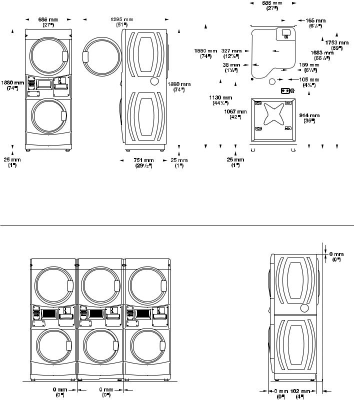
DIMENSIONS/CLEARANCES |
|||||||||||||||||||||||||||||||||||||
|
|
|
|
|
|
|
|
|
|
|
|
|
|
|
|
|
|
|
|
|
|
|
|
|
|
|
|
|
|
|
|
|
|
|
|
|
|
|
|
|
|
|
|
|
|
|
|
|
|
|
|
|
|
|
|
|
|
|
|
|
|
|
|
|
|
|
|
|
|
|
|
|
|
|
|
Dimensions |
|
|
|
|
|
|
|
|
|
|
|
|
|
|
|
|
|
|
|
|
|
|
|
|
|
|
|
|
|
|
|
|
|
|
|
|
|
|
|
|
|
|
|
|
|
|
|
|
|
|
|
|
|
|
|
|
|
|
|||||||||||||||||
|
|
|
|
|
|
|
|
|
|
||||||||||||||||||||||||||||||||||||||||||||||||||||||||||||||||||
Front View |
Side View |
|
|
|
|
|
|
|
Back View |
||||||||||||||||||||||||||||||||||||||||||||||||||||||||||||||||||
|
|
|
|
|
|
|
|
|
|
|
|
|
|
|
|
|
|
|
|
|
|
|
|
|
|
|
|
|
|
|
|
|
|
|
|
|
|
|
|
|
|
|
|
|
|
|
|
|
|
|
|
|
|
|
|
|
|
|
|
|
|
|
|
|
|
|
|
|
|
|
|
|
|
|
|
|
|
|
|
|
|
|
|
|
|
|
|
|
|
|
|
|
|
|
|
|
|
|
|
|
|
|
|
|
|
|
|
|
|
|
|
|
|
|
|
|
|
|
|
|
|
|
|
|
|
|
|
|
|
|
|
|
|
|
|
|
|
|
|
|
|
|
|
|
|
|
|
|
|
|
|
|
|
|
|
|
|
|
|
|
|
|
|
|
|
|
|
|
|
|
|
|
|
|
|
|
|
|
|
|
|
|
|
|
|
|
|
|
|
|
|
|
|
|
|
|
|
|
|
|
|
|
|
|
|
|
|
|
|
|
|
|
|
|
|
|
|
|
|
|
|
|
|
|
|
|
|
|
|
|
|
|
|
|
|
|
|
|
|
|
|
|
|
|
|
|
|
|
|
|
|
|
|
|
|
|
|
|
|
|
|
|
|
|
|
|
|
|
|
|
|
|
|
|
|
|
|
|
|
|
|
|
|
|
|
|
|
|
|
|
|
|
|
|
|
|
|
|
|
|
|
|
|
|
|
|
|
|
|
|
|
|
|
|
|
|
|
|
|
|
|
|
|
|
|
|
|
|
|
|
|
|
|
|
|
|
|
|
|
|
|
|
|
|
|
|
|
|
|
|
|
|
|
|
|
|
|
|
|
|
|
|
|
|
|
|
|
|
|
|
|
|
|
|
|
|
|
|
|
|
|
|
|
|
|
|
|
|
|
|
|
|
|
|
|
|
|
|
|
|
|
|
|
|
|
|
|
|
|
|
|
|
|
|
|
|
|
|
|
|
|
|
|
|
|
|
|
|
|
|
|
|
|
|
|
|
|
|
|
|
|
|
|
|
|
|
|
|
|
|
|
|
|
|
|
|
|
|
|
|
|
|
|
|
|
|
|
|
|
|
|
|
|
|
|
|
|
|
|
|
|
|
|
|
|
|
|
|
|
|
|
|
|
|
|
|
|
|
|
|
|
|
|
|
|
|
|
|
|
|
|
|
|
|
|
|
|
|
|
|
|
|
|
|
|
|
|
|
|
|
|
|
|
|
|
|
|
|
|
|
|
|
|
|
|
|
|
|
|
|
|
|
|
|
|
|
|
|
|
|
|
|
|
|
|
|
|
|
|
|
|
|
|
|
|
|
|
|
|
|
|
|
|
|
|
|
|
|
|
|
|
|
|
|
|
|
|
|
|
|
|
|
|
|
|
|
|
|
|
|
|
|
|
|
|
|
|
|
|
|
|
|
|
|
|
|
|
|
|
|
|
|
|
|
|
|
|
|
|
|
|
|
|
|
|
|
|
|
|
|
|
|
|
|
|
|
|
|
|
|
|
|
|
|
|
|
|
|
|
|
|
|
|
|
|
|
|
|
|
|
|
|
|
|
|
|
|
|
|
|
|
|
|
|
|
|
|
|
|
|
|
|
|
|
|
|
|
|
|
|
|
|
|
|
|
|
|
|
|
|
|
|
|
|
|
|
|
|
|
|
|
|
|
|
|
|
|
|
|
|
|
|
|
|
|
|
|
|
|
|
|
|
|
|
|
|
|
|
|
|
|
|
|
|
|
|
|
|
|
|
|
|
|
|
|
|
|
|
|
|
|
|
|
|
|
|
|
|
|
|
|
|
|
|
|
|
|
|
|
|
|
|
|
|
|
|
|
|
|
|
|
|
|
|
|
|
|
|
|
|
|
|
|
|
|
|
|
|
|
|
|
|
|
|
|
|
|
|
|
|
|
|
|
|
|
|
|
|
|
|
|
|
|
|
|
|
|
|
|
|
|
|
|
|
|
|
|
|
|
|
|
|
|
|
|
|
|
|
|
|
|
|
|
|
|
|
|
|
|
|
|
|
|
|
|
|
|
|
|
|
|
|
|
|
|
|
|
|
|
|
|
|
|
|
|
|
|
|
|
|
|
|
|
|
|
|
|
|
|
|
|
|
|
|
|
|
|
|
|
|
|
|
|
|
|
|
|
|
|
|
|
|
|
|
|
|
|
|
|
|
|
|
|
|
|
|
|
|
|
|
|
|
|
|
|
|
|
|
|
|
|
|
|
|
|
|
|
|
|
|
|
|
|
|
|
|
|
|
|
|
|
|
|
|
|
|
|
|
|
|
|
|
|
|
|
|
|
|
|
|
|
|
|
|
|
|
|
|
|
|
|
|
|
|
|
|
|
|
|
|
|
|
|
|
|
|
|
|
|
|
|
|
|
|
|
|
|
|
|
|
|
|
|
|
|
|
|
|
|
|
|
|
|
|
|
|
|
|
|
|
|
|
|
|
|
|
|
|
|
|
|
|
|
|
|
|
|
|
|
|
|
|
|
|
|
|
|
|
|
|
|
|
|
|
|
|
|
|
|
|
|
|
|
|
|
|
|
|
|
|
|
|
|
|
|
|
|
|
|
|
|
|
|
|
|
|
|
|
|
|
|
|
|
|
|
|
|
|
|
|
|
|
|
|
|
|
|
|
|
|
|
|
|
|
|
|
|
|
|
|
|
|
|
|
|
|
|
|
|
|
|
|
|
|
|
|
|
|
|
|
|
|
|
|
|
|
|
|
|
|
|
|
|
|
|
|
|
|
|
|
|
|
|
|
|
|
|
|
|
|
|
|
|
|
|
|
|
|
|
|
|
|
|
|
|
|
|
|
|
|
|
|
|
|
|
|
|
|
|
|
|
|
|
|
|
|
|
|
|
|
|
|
|
|
|
|
|
|
|
|
|
|
|
|
|
|
|
|
|
|
|
|
|
|
|
|
|
|
|
|
|
|
|
|
|
|
|
|
|
|
|
|
|
|
|
|
|
|
|
|
|
|
|
|
|
|
|
|
|
|
|
|
|
|
|
|
|
|
|
|
|
|
|
|
|
|
|
|
|
|
|
|
|
|
|
|
|
|
|
|
|
|
|
|
|
|
|
|
|
|
|
|
|
|
|
|
|
|
|
|
|
|
|
|
|
|
|
|
|
|
|
|
|
|
|
|
|
|
|
|
|
|
|
|
|
|
|
|
|
|
|
|
|
|
|
|
|
|
|
|
|
|
|
|
|
|
|
|
|
|
|
|
|
|
|
|
|
|
|
|
|
|
|
|
|
|
|
|
|
|
|
|
|
|
|
|
|
|
|
|
|
|
|
|
|
|
|
|
|
|
|
|
|
|
|
|
|
|
|
|
|
|
|
|
|
|
|
|
|
|
|
|
|
|
|
|
|
|
|
|
|
|
|
|
|
|
|
|
|
|
|
|
|
|
|
|
|
|
|
|
|
|
|
|
|
|
|
|
|
|
|
|
|
|
|
|
|
|
|
|
|
|
|
|
|
|
|
|
|
|
|
|
|
|
|
|
|
|
|
|
|
|
|
|
|
|
|
|
|
|
|
|
|
|
|
|
|
|
|
|
|
|
|
|
|
|
|
|
|
|
|
|
|
|
|
|
|
|
|
|
|
|
|
|
|
|
|
|
|
|
|
|
|
|
|
|
|
|
|
|
|
|
|
|
|
|
|
|
|
|
|
|
|
|
|
|
|
|
|
|
|
|
|
|
|
|
|
|
|
|
|
|
|
|
|
|
|
|
|
|
|
|
|
|
|
|
|
|
|
|
|
|
|
|
|
|
|
|
|
|
|
|
|
|
|
|
|
|
|
|
|
|
|
|
|
|
|
|
|
|
|
|
|
|
|
|
|
|
|
|
|
|
|
|
|
|
|
|
|
|
|
|
|
|
|
|
|
|
|
|
|
|
|
|
|
|
|
|
|
|
|
|
|
|
|
|
|
|
|
|
|
|
|
|
|
|
|
|
|
|
|
|
|
|
|
|
|
|
|
|
|
|
|
|
|
|
|
|
|
|
|
|
|
|
|
|
|
|
|
|
|
|
|
|
|
|
|
|
|
|
|
|
|
|
|
|
|
|
|
|
|
|
|
|
|
|
|
|
|
|
|
|
|
|
|
|
|
|
|
|
|
|
|
|
|
|
|
|
|
|
|
|
|
|
|
|
|
|
|
|
|
|
|
|
|
|
|
|
|
|
|
|
|
|
|
|
|
|
|
|
|
|
|
|
|
|
|
|
|
|
|
|
|
|
|
|
|
|
|
|
|
|
|
|
|
|
|
|
|
|
|
|
|
|
|
|
|
|
|
|
|
|
|
|
|
|
|
|
|
|
|
|
|
|
|
|
|
|
|
|
|
|
|
|
|
|
|
|
|
|
|
|
|
|
|
|
|
|
|
|
|
|
|
|
|
|
|
|
|
|
|
|
|
|
|
|
|
|
|
|
|
|
|
|
|
Clearances
Side Clearances Back/Top Clearances
9
STACKED WASHER/GAS DRYER INSTALLATION REQUIREMENTS
(Australia and New Zealand – for full details of installation requirements refer to AS/NZS 5601.1 – Gas Installations)
Stacked Washer/Gas Dryer Location
Selecting the proper location for your washer/dryer improves performance and minimizes noise and possible washer “walk.”
Your washer/dryer can be installed in a basement, laundry room, or recessed area. See “Drain System.”
Companion appliance location requirements should also be considered.
IMPORTANT: Do not install or store the washer/dryer where it will be exposed to the weather. Do not store or operate the washer/ dryer in temperatures at or below 0°C (32°F). Some water can remain in the washer and can cause damage in low temperatures. Proper installation is your responsibility.
You will need:
νA water heater set to deliver 49°C (120°F) water to the washer.
νA grounded electrical outlet located within 1.8 m (6 ft.) of where the power cord is attached to the back of the washer. See “Electrical Requirements.”
νHot and cold water faucets located within 1.2 m (4 ft.) of the hot and cold water fill valves, and water pressure of 137.9–689.6 kPa (20–100 psi).
νA level floor with a maximum slope of 25 mm (1") under entire washer/dryer. Installing the washer/dryer on soft floor
surfaces, such as carpets or surfaces with foam backing, is not recommended.
νA sturdy and solid floor to support the washer/dryer with a total weight (water and load) of 204 kg (450 lbs).
νA floor drain under the bulkhead. Prefabricated bulkheads with electrical outlets, water inlet lines, and drain facilities should be used only where local codes permit.
Stacked washer/gas dryer installation clearances
νThe location must be large enough to allow the washer and dryer doors to be fully opened.
νAdditional spacing should be considered for ease of installation and servicing. The doors open more than 180°. The washer door is not reversible.
νAdditional clearances might be required for wall, door, and floor moldings.
νAdditional spacing of 25 mm (1") on all sides of the washer/dryer is recommended to reduce noise transfer.
νCompanion appliance spacing should also be considered.
When installing a gas dryer:
IMPORTANT: Observe all governing codes and ordinances.
νCheck code requirements: Some codes limit or do not permit installation of clothes dryers in garages, closets, or sleeping quarters. Contact your local building inspector.
NOTE: For installation in Australia and New Zealand, install dryer in accordance with AS/NZS 5601.1 and local governance codes.
νMake sure that lower edges of the cabinet, plus the back and bottom sides of the washer, are free of obstructions to permit adequate clearance of air openings for combustion air. See “Recessed Area and Closet Installation Instructions” below for minimum spacing requirements.
νDo not install on carpet.
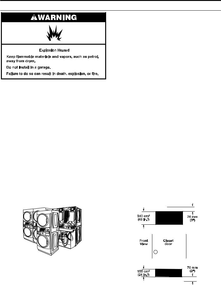
Recessed Area and Closet Installation Instructions
This washer/dryer may be installed in a recessed area or closet. This washer/dryer must not be installed behind a lockable door, a sliding door, or a door with a hinge on the opposite side to that of the washer/dryer. For recessed area and closet installations, minimum clearances can be found on the warning label on the rear of the dryer or in “Dimensions/Clearances.”
The installation spacing is in millimeters and is the minimum allowable. Additional spacing should be considered for ease of installation, servicing, and compliance with local codes and ordinances.
If closet door is installed, the minimum unobstructed air opening in the top and bottom is required. Louvered doors with equivalent air openings are acceptable.
The dryer must be exhausted outdoors.
No other fuel-burning appliance may be installed in the same closet as the washer/dryer.
NOTE: For installation in Australia and New Zealand, refer to AS/NZS 5601.1 for ventilation requirements.
10
STACKED WASHER/GAS DRYER INSTALLATION REQUIREMENTS
Stacked Washer/Gas Dryer Electrical Requirements
IMPORTANT: Observe all governing codes and ordinances.
You will need an earthed electrical outlet located within 610 mm (2 feet) of either side of the washer/dryer.
This washer/dryer is supplied/fitted with an electrical supply cord and plug. It should be connected to electrical supply socket at the voltage shown on the rating plate. The minimum supply fuse capacity should be 5A. The washer/dryer must be positioned so
that the plug is clearly visible and accessible. This plug also provides the function of an emergency stop control for the user. If the fitted plug is not used, the electrical connection must be carried out by a competent electrician in accordance with local or national codes.
If the supply cord is damaged, it must be replaced with a specially terminated cord by an authorized service agent or a similarly competent person in order to avoid a hazard.
Do not use an adapter.
Do not use an extension cord.
NOTE: In accordance with the European EMC Directive (2004/108/EC), the maximum electricity supply system impedance to which the gas dryer should be connected is declared to be 0.054 Ohm + j0.034 Ohm.
NOTE: Electrical safety standards: The manufacturer has chosen compliance with IEC/EN.60335 standards as the most appropriate for this product.
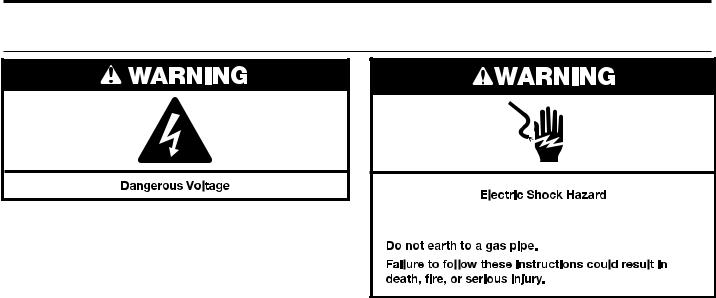
EARTHING INSTRUCTIONS
SAVE THESE INSTRUCTIONS
Using the universal cord included with this dryer:
The gas dryer is equipped with a universal cord with interchangeable plugs.
1.To use the universal cord, select the plug end that fits your electrical outlet, and plug it into the adapter on the supply cord.
2.Secure the plug end in place on the cord by aligning the 2 cover halves over the cord adapter and clipping them together.
If codes permit and an additional earth bond wire is used, it is recommended that a qualified electrician determine that the earth bond path is adequate.
11
STACKED WASHER/GAS DRYER INSTALLATION REQUIREMENTS
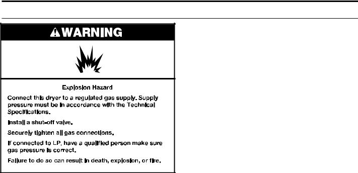
Stacked Washer/Gas Dryer Gas Supply Requirements
IMPORTANT: Observe all governing codes and ordinances. In Australia and New Zealand, refer to AS/NZS 5601.1 – Gas Installations.
Gas Supply
Before installation, check that the local gas distribution conditions, nature of gas and pressure, and the adjustment of the appliance are compatible. Burner information will be found on the model/ serial rating plate in the door recess of the dryer. If this information does not agree with the type of gas available, see your dealer.
Natural Gas:
This dryer is factory adjusted for use with NATURAL GAS (G20), and no further adjustment should be required at installation.
L.P. Gas:
This dryer is also certified for use with L.P. (propane or butane) gases with appropriate conversion. No attempt shall be made to convert the appliance from the gas specified on the model/serial rating plate for use with a different gas without consulting the serving gas supplier.
Conversion must be done by a competent service technician. Gas conversion kit (European Country), part number W10233219,
is available for purchase from your dealer. Gas conversion kit (Australia), part number W10315369, is available for purchase from your dealer. Full instructions are supplied with the kit.
Natural gas (France/Belgium):
This dryer is also certified for France/Belgium for use with G20/ G25 gases (20 mbar/25 mbar) with appropriate conversion. No attempt should be made to convert this appliance from the gas specified on the gas rating label for use with a different gas
without consulting the serving gas supplier. Gas conversion must be done by a qualified gas service technician. Conversion kit, part number (W10181947) is available for purchase from your dealer. Full instructions are supplied with the kit.
Supply line requirements:
Provide a rigid gas supply line to the washer/dryer location. It should be minimum 12.5 mm (1/2") ID. When acceptable to the gas supplier and local codes, 10 mm (3/8") ID rigid supply line may be used for lengths under 6.1 m (20'). Pipe-joint compounds resistant to the action of L.P. gas must be used.
NOTE: For installation in Australia and New Zealand, refer to AS/NZS 5601 for pipe sizing details. All piping is to be in accordance with AS/NZS 5601.1 – Gas Installations.
Gas connection to the dryer itself should be made by means
of a flexible gas hose suitable for the appliance and gas category in accordance with national installation regulations. If in doubt, contact the gas supplier. It should be minimum 10 mm (3/8") ID.
A means of restraint should be used between the washer/dryer and the wall to avoid straining of the rigid gas supply when the washer/dryer is moved. An appropriate length of chain and a wall hook is recommended.
The dryer gas inlet connection is a 3/8" NPT thread. An adapter is supplied for conversion to standard ISO.228-1 thread (3/8" BSP).
Check for leaks by using an approved noncorrosive leak-detection solution. Bubbles will show a leak. Correct any leak found. A pressure measurement tapping is provided on the gas valve within the dryer, accessible after removal of the lower front panel.
The dryer must be disconnected from the gas supply piping system during any pressure testing of that system.
12
STACKED WASHER/ELECTRIC DRYER INSTALLATION REQUIREMENTS
Stacked Washer/Electric Dryer Location
NOTE: In Australia and New Zealand, refer to AS/NZS 5601.1 – Gas Installations.
Selecting the proper location for your washer/dryer improves performance and minimizes noise and possible washer “walk.”
Your washer/dryer can be installed in a basement, laundry room, or recessed area. See “Drain System.”
Companion appliance location requirements should also be considered.
IMPORTANT: Do not install or store the washer/dryer where it will be exposed to the weather. Do not store or operate the washer/ dryer in temperatures at or below 0°C (32°F). Some water can remain in the washer and can cause damage in low temperatures. Proper installation is your responsibility.
You will need:
νA water heater set to deliver 49°C (120°F) water to the washer.
νA grounded electrical outlet located within 1.8 m (6 ft.) of where the power cord is attached to the back of the washer. See “Electrical Requirements.”
νHot and cold water faucets located within 1.2 m (4 ft.) of the hot and cold water fill valves, and water pressure of 137.9–689.6 kPa (20–100 psi).
νA level floor with a maximum slope of 25 mm (1") under entire washer/dryer. Installing the washer/dryer on soft floor
surfaces, such as carpets or surfaces with foam backing, is not recommended.
νA sturdy and solid floor to support the washer/dryer with a total weight (water and load) of 204 kg (450 lbs).
νA floor drain under the bulkhead. Prefabricated bulkheads with electrical outlets, water inlet lines, and drain facilities should be used only where local codes permit.
Stacked washer/electric dryer installation clearances
νThe location must be large enough to allow the washer and dryer doors to be fully opened.
νAdditional spacing should be considered for ease of installation and servicing. The doors open more than 180°. The washer door is not reversible.
νAdditional clearances might be required for wall, door, and floor moldings.
νAdditional spacing of 25 mm (1") on all sides of the washer/dryer is recommended to reduce noise transfer.
νCompanion appliance spacing should also be considered.
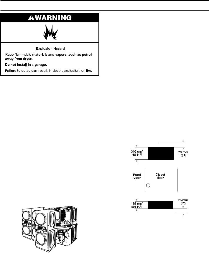
Recessed Area and Closet Installation Instructions
This washer/dryer may be installed in a recessed area or closet. This washer/dryer must not be installed behind a lockable door, a sliding door, or a door with a hinge on the opposite side to that of the washer/dryer. For recessed area and closet installations, minimum clearances can be found on the warning label on the rear of the dryer or in “Dimensions/Clearances.”
The installation spacing is in millimeters and is the minimum allowable. Additional spacing should be considered for ease of installation, servicing, and compliance with local codes and ordinances.
If closet door is installed, the minimum unobstructed air opening in the top and bottom is required. Louvered doors with equivalent air openings are acceptable.
The dryer must be exhausted outdoors.
No other fuel-burning appliance may be installed in the same closet as the washer/dryer.
13
STACKED WASHER/ELECTRIC DRYER INSTALLATION REQUIREMENTS
Stacked Washer/Electric Dryer Electrical
Requirements
This washer/dryer is supplied without an electric cord and plug. It must be connected by a competent electrician to a single-phase electricity supply at the voltage shown on the dataplate, using
a suitable fixed wiring installation in accordance with local and national wiring regulations.
νA 3-wire circular cord of minimum conductor size 2.5 mm2 cross-section area should be used.
νA 30A supply fuse should be used, and a switch having a contact separation in both poles that provides full
disconnection under over-voltage category III conditions must be incorporated into the fixed wiring in accordance with local wiring regulations. The washer/dryer should be positioned
so that the disconnection switch is clearly visible and easily accessible to the user. This disconnection switch also provides the function of an emergency stop control for the user.
νA cord clamp bush is provided on the washer/dryer, and should be tightened on completion of wiring. The electrical mains terminals are located behind the small rear access panel (terminal block cover), and connections should be made in accordance with the terminal markings. Remember to replace the terminal access panel (terminal block cover).
NOTE: In accordance with the European EMC Directive (2004/108/EC), the maximum electrical supply system impedance to which the electric dryer should be connected is declared to be 0.054 Ohm + j0.034 Ohm.
NOTE: Electrical safety standards: The manufacturer has chosen compliance with IEC/EN.60335 standards as the most appropriate for this product.
This is 3-wire appliance which must be earthed.
If codes permit and an additional earth bond wire is used, it is recommended that a qualified electrician determine that the earth bond path is adequate.
Recommended Earthing Method
It is your responsibility to contact a qualified electrical installer to ensure that the electrical installation is adequate and in conformance with all local codes and ordinances.
14
DRYER VENTING REQUIREMENTS
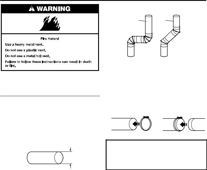
WARNING: To reduce the risk of fire, this dryer MUST BE EXHAUSTED OUTDOORS.
IMPORTANT: Observe all governing codes and ordinances. In Australia and New Zealand, refer to AS/NZS 5601.1 – Gas Installations.
■■ Following these venting requirements will minimise ducting air noise.
■■ Adequate ventilation has to be provided to avoid the backflow of gases into the room from appliances burning other fuels, including open fires (i.e. available airflow into the room should match airflow out from the room).
■■ Dryer exhaust must not be connected into any gas vent, chimney, wall, ceiling, attic, crawlspace, or a concealed space of a building. Only rigid or flexible metal vent shall be used for exhausting.
■■ Do not use an exhaust hood with a magnetic latch.
102 mm (4")
102 mm (4") Heavy, Metal Exhaust Vent
■■ Only a 4" (102 mm) heavy, metal exhaust vent and clamps may be used.
■■ Do not use plastic or metal foil vent.
Rigid metal vent:
■■ Recommended for best drying performance and to avoid crushing and kinking.
Flexible metal vent: (Acceptable only if accessible to clean)
■■ Must be fully extended and supported in final dryer location.
■■ Remove excess to avoid sagging and kinking that may result in reduced airflow and poor performance.
■■ Do not install in enclosed walls, ceilings, or floors. ■■ The total length should not exceed 73⁄4 ft. (2.4 m).
■■ An exhaust hood should cap the vent to keep rodents and insects from entering the building.
NOTE: If using an existing vent system, clean lint from entire length of the system and make sure exhaust hood is not plugged with lint. Replace plastic or metal foil vents with rigid metal or flexible metal vents. Review “Vent System Chart” and if necessary, modify existing vent system to achieve best drying performance.
Elbows:
■■ 45° elbows provide better airflow than 90° elbows.
Good |
Better |
■■ Plan installation to use the fewest number of elbows and turns.
■■ Allow as much room as possible when using elbows or making turns. Bend vent gradually to avoid kinking.
■■ Vent outlet is located at the center of the bottom dryer back.
■■ The vent can be routed up, down, left, right, behind the dryer, or straight out the back of the dryer.
Clamps:
■■ Use clamps to seal all joints.
■■ Exhaust vent must not be connected or secured with screws or other fastening devices that extend into interior of duct and catch lint. Do not use duct tape.
Improper venting can cause moisture and lint to collect indoors, which may result in:
 Moisture damage to woodwork, furniture, paint, wallpaper, carpets, etc.
 Housecleaning problems and health problems.
15

DRYER VENTING REQUIREMENTS
(In Australia and New Zealand, refer to AS/NZS 5601.1 – Gas Installations)
Vent Hoods
102 mm (4") Diameter Exhaust Hoods |
Exhaust hood must be at least 305 mm (12") from the ground or |
|
any object that may be in the path of the exhaust (such as flowers, |
|
rocks, bushes, or snow). |
Box Hood |
Louvered Hood |
Angled Hood |
30512" mmin.min.
 (305(12")mm)
Vent System Length
Maximum Vent Length/Vent Connection
Maximum length of vent system depends upon the type of vent used, number of elbows, and type of exhaust hood.
Vent System Chart (Rigid Metal Vent)
No. of |
Box and |
Angled |
|
90˚ Turns |
Louvered Hood |
Hood |
|
0 |
39.6 m (130 ft.) |
39.3 m (129 ft.) |
|
1 |
38.1 m (125 ft.) |
36.3 m (119 ft.) |
|
2 |
35.1 m. (115 ft) |
33.2 m (109 ft.) |
|
3 |
32.3 m (106 ft.) |
30.5 m (100 ft.) |
|
4 |
29.9 m (98 ft.) |
28.0 m (92 ft.) |
|
For vent systems not covered by the vent specification chart, see your parts distributor.
Provision must be made for enough air for combustion and ventilation. (Check governing codes and ordinances.) See “Recessed Area and Closet Installation Instructions” in the “Stacked Washer/Gas Dryer Location” and “Stacked Washer/ Electric Dryer Location” sections.
A 102 mm (4") outlet hood is preferred. However, a 64 mm (21⁄2") outlet exhaust hood may be used. A 64 mm (21⁄2") outlet creates greater back pressure than other hood types. For permanent installation, a stationary vent system is required.
Connect Vent
1.If connecting to existing vent, make sure the vent is clean.
2.Using a 102 mm (4") clamp, connect vent to exhaust outlet in
dryer.
3. Tighten hose clamp with Phillips screwdriver.
4.Make sure the vent is secured to exhaust hood with a 102 mm (4") clamp.
5.Move dryer into final position. Do not crush or kink vent. Make sure dryer is level.
NOTE: Do not remove vent collar.
16
DRYER VENTING REQUIREMENTS
(In Australia and New Zealand, refer to AS/NZS 5601.1 – Gas Installations)
If an Exhaust Hood Cannot be Used
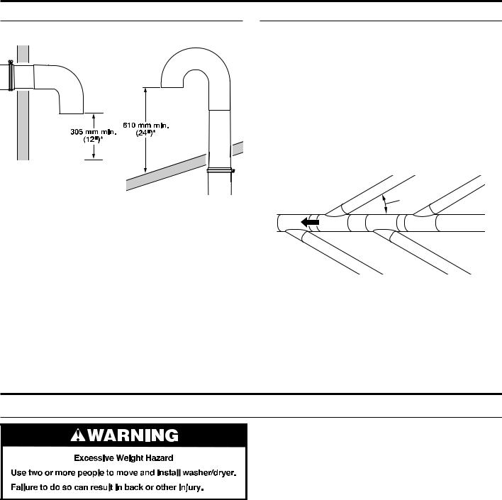
The outside end of main vent should have a sweep elbow directed downward.
*Minimum clearance above any accumulation of snow, ice, or debris such as leaves
If main vent travels vertically through the roof, rather than through wall, install a 180° sweep elbow on end of vent at least 610 mm (2 ft.) above surface of roof.
The opening in wall or roof shall have a diameter 13 mm (1⁄2") larger than vent diameter. Vent should be centered in opening.
Do not install screening over end of vent for best performance.
Multiple Dryer Venting
A main vent can be used for venting a group of dryers. The main vent should be sized to remove 5663 l/min. (200 CFM) of air per dryer. Large-capacity lint screens of proper design may be used in main vent if checked and cleaned frequently. The room where the dryers are located should have make-up air equal to or greater than CFM of all the dryers in the room.
Back-draft Damper Kit, Part No. 3391910, is available from your distributor and should be installed in the vent of each dryer to keep exhausted air from returning into dryers and to keep exhaust in balance within main vent. Unobstructed return air openings are required.
Each vent should enter the main vent at an angle pointing in the direction of the airflow. Vents entering from the opposite side should be staggered to reduce the exhausted air from interfering with the other vents.
 air ow
The maximum angle of each vent entering the main vent should be no more than 30°.
Keep air openings free of dry cleaning fluid fumes. Fumes create acids which, when drawn through the dryer heating units, can damage dryers and items being dried.
A clean-out cover should be located on the main vent for periodic cleaning of the vent system.
DRYER GAS SUPPLY REQUIREMENTS
(All piping is to be in accordance with AS/NZS 5601.1 – Gas Installations)
Make Gas Connection
1.Remove red cap from gas pipe.
2.Connect gas supply to dryer. If the flexible gas hose has
10 mm (3/8") BSP thread, use the supplied conversion thread adapter. Use pipe-joint compound resistant to the action of L.P. gas for gas connections.
If necessary for service, open the toe panel. Use a putty knife to press on the 2 toe panel locks located at the top of the toe panel. Pull downward on the toe panel to open. Toe panel is hinged at the bottom.
3.Open the shut-off valve in the gas supply line.
4.Test all connections by brushing on an approved noncorrosive leak-detection solution. Bubbles will show a leak. Correct any leaks found.
17
INSTALLING STACKED WASHER/DRYER
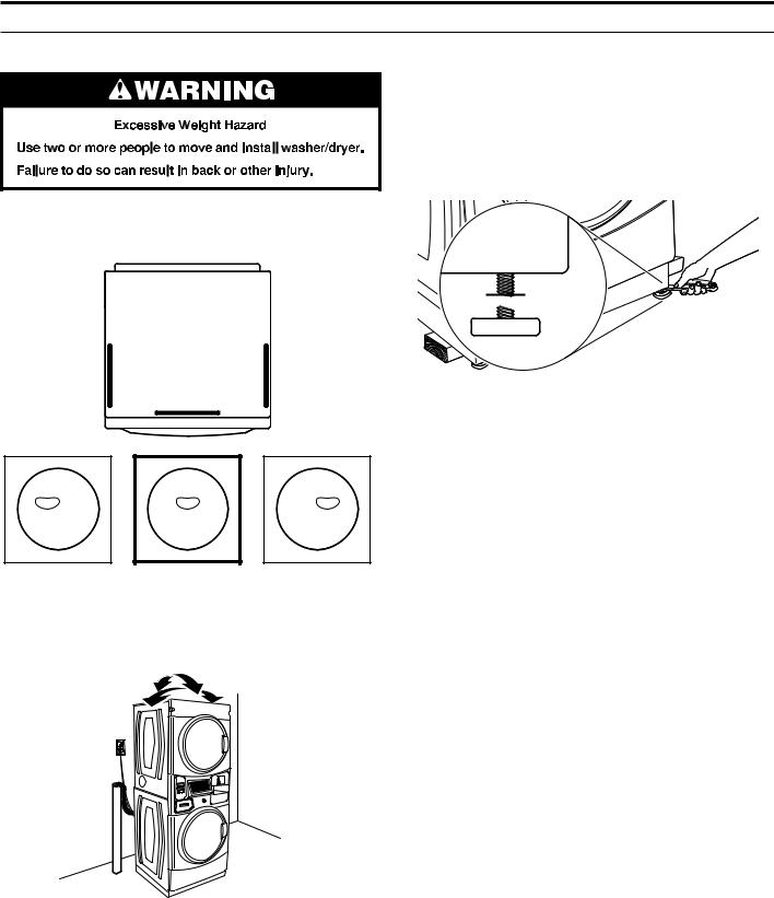
Remove Transport System
NOTE: Slide washer/dryer onto cardboard or hardboard before moving to avoid damaging floor covering.
IMPORTANT: Position the washer/dryer so that the rear of the washer is within approximately 900 mm (3 ft.) of its final location.
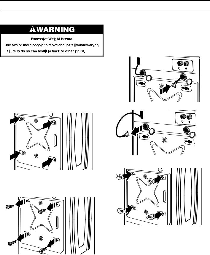
There are four shipping bolts in the rear panel of the washer that support the suspension system during transportation. These bolts also retain the power cord inside the washer until the bolts are removed.
IMPORTANT: Remove the four shipping bolts at the rear of the washer before operation.
1.Keep the washer/dryer in the upright position while removing the shipping bolts.
2.Using a 13 mm (1/2") wrench, loosen each of the bolts.
4.Models with separate washer power cords: Push the power cord plug into the opening on the right side of the rear panel and pull the power cord through the opening on the left side of the rear panel and close holes with the attached cap. Do not pull plug end of power cord through the right side hole.
NOTE: To avoid damage to internal washer parts or the power cord, if the cord does not pull out of the washer rear panel easily, do not force it. Remove the washer rear panel and guide the power cord around the obstruction and out the hole on the left side of the rear panel.
5. Close the bolt holes with the 4 transport bolt hole plugs.
3. Once the bolt is loose, move it to the center of the hole
and completely pull out the bolt, including the plastic spacer covering the bolt. Once all 4 bolts are removed, discard the bolts and spacers.
IMPORTANT: If the washer/dryer is to be transported, call your product distributor or installer. To avoid suspension and structural damage, your washer/dryer must be properly set up for relocation by a trained professional.
18
INSTALLING STACKED WASHER/DRYER
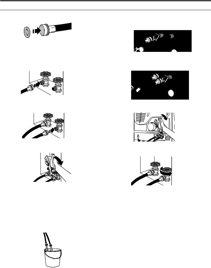
Connect Inlet Hoses
Insert new hose washers (supplied) into each end of the inlet hoses. Firmly seat the washers in the couplings.
Washer Coupling
Connect Inlet Hoses to Water Faucets
Make sure the washer drum is empty.
1.Attach a hose to the hot water faucet. Screw on coupling by hand until it is seated on the washer.
2.Attach a hose to the cold water faucet. Screw on coupling by hand until it is seated on the washer.
3.Using pliers, tighten the couplings with an additional two-thirds turn.
NOTE: Do not overtighten or use tape or sealants on the valve. Damage to the valves can result.
Clear Water Lines
νRun water through both faucets and inlet hoses, into a laundry tub, drainpipe, or bucket, to get rid of particles
in the water lines that might clog the inlet valve screens.
νCheck the temperature of the water to make sure that the hot water hose is connected to the hot water faucet and that the cold water hose is connected to the cold water faucet.
Connect Inlet Hoses to Washer
1.Attach the cold water hose to the washer’s cold water inlet valve. Screw on coupling by hand until it is seated on the washer.
2.Attach the hot water hose to the washer’s hot water inlet valve. Screw on coupling by hand until it is seated on the washer.
3.Using pliers, tighten the couplings with an additional two-thirds turn.
NOTE: Do not overtighten. Damage to the valve can result. 4. Turn on the water faucets completely and check for leaks.
NOTE: Replace inlet hoses after 5 years of use to reduce the risk of hose failure. Record hose installation or replacement dates on the hoses for future reference.
Periodically inspect and replace hoses if bulges, kinks, cuts, wear, or leaks are found.
19

INSTALLING STACKED WASHER/DRYER
Route Drain Hose
Proper routing of the drain hose avoids damage to your floor due to water leakage. Read and follow these instructions.
Remove drain hose from the washer drum
1.Using locking pliers, squeeze hose clamp tabs together and insert over the end of the drain hose.
2. Slide the drain hose onto the washer connection.
3. Once the drain hose is in place, release the pliers.
4.The washer drain system can be installed using a floor drain, wall standpipe, floor standpipe, or laundry tub.
Laundry tub drain or standpipe drain
Connect the drain hose form to the corrugated drain hose.
Snap either end of the drain hose form to the drain hose at the point where the corrugation begins.
Bend drain hose over drain hose form and snap into place.
NOTE: Hose must not extend more than 25 mm (1") past the end of the U bend.
To keep drain water from going back into the washer:
νDo not straighten the drain hose, do not force excess drain hose into standpipe. Hose should be secure, but loose enough to provide a gap for air.
νDo not lay excess hose on the bottom of the laundry tub.
Floor drain
You may need additional parts. See “Alternate Parts.”
Secure Drain Hose
1.Drape the power cord over the washer top.
2.Move the washer to its final location.
3.Place the drain hose
in the laundry tub or standpipe as shown.
4. Secure the drain hose using the supplied beaded tie strap.
5.If the washer faucets and the drain standpipe are recessed, put the hooked end of the drain hose in
the standpipe as shown.
NOTES:
ν Do not force excess drain hose back into the rear of the washer.
ν To avoid siphoning, do not seal the drain hose into the standpipe.
20
WASHER DRAIN SYSTEM
The washer can be installed using the standpipe drain system (floor or wall), the laundry tub drain system, or the floor drain system.
Standpipe drain system – wall or floor
The standpipe drain requires a minimum diameter standpipe of 50 mm (2"). The minimum carry-away capacity can be no less than 38 L (10 gal.) per minute.
Wall
The top of the standpipe must be at least 762 mm (30") high and no higher than 2.4 m (96") from the bottom of the washer.
Floor
Laundry tub drain system
The laundry tub needs a minimum 76 L (20 gal.) capacity. The top of the laundry tub must be at least 762 mm (30") above the floor.
Floor drain system
The floor drain system requires a siphon break that may be purchased separately.
The siphon break (Part Number 285834) must be a minimum
of 710 mm (28") from the bottom of the washer. Additional hoses might be needed.
Syphon-
Break
21
LEVELING
Leveling Stacked Washer/Dryer
Leveling your washer/dryer properly reduces excess noise and vibration.
1.Remove cardboard from beneath washer/dryer. Place a level on top edges of washer/dryer, checking each side and front. If not level, tip washer/dryer and adjust feet up or down as shown in Steps 3 and 4, repeating as necessary.
3.If washer/dryer is not level, use a 14 mm or 9/16" openend or adjustable wrench to turn jam nuts clockwise (as
viewed from above) on feet until they are about 13 mm (1/2") from the washer/dryer cabinet. Then turn the leveling foot counterclockwise to lower the washer/dryer or clockwise to raise the washer/dryer. Recheck levelness of washer/dryer and that all four feet are firmly in contact with the floor. Repeat as needed.
HELPFUL TIP: You may want to prop up front of washer/dryer about 102 mm (4") with a wood block or similar object that will support weight of washer/dryer.


 Jam nut
4.When washer/dryer is level and all four feet are firmly in contact with the floor, use a 14 mm or 9/16" open-end or adjustable wrench to turn jam nuts counterclockwise (as viewed from above) on leveling feet tightly against washer/dryer cabinet.
HELPFUL TIP: You may want to prop washer/dryer with wooden block.
|
|
|
|
|
|
|
|
|
|
|
Not Level |
|
LEVEL |
|
Not Level |
||||||
2.Grip washer/dryer from top and rock back and forth, making sure all four feet are firmly on floor. Repeat, rocking washer/dryer from side to side. If washer/dryer rocks, go to Step 3 and adjust leveling feet. If all four feet are in firm contact with floor, go to Step 4.
22
COMPLETE INSTALLATION
1.Check the electrical requirements. Be sure that you have the correct electrical supply and the recommended grounding method. See “Electrical Requirements.”
2.Check that all parts are now installed. If there is an extra part, go back through the steps.
3.Check that you have all of your tools.
4.Dispose of/recycle all packaging materials.
5.Check that the water faucets are on.
6.Check for leaks around faucets and inlet hoses.
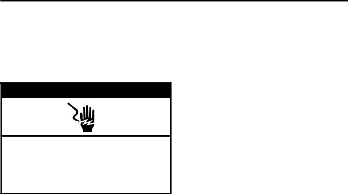
 WARNING
Electric Shock Hazard This washer/dryer must be earthed. Securely tighten all electrical connections.
Failure to do so can result in death, fire, or electric shock.
7. Plug into a grounded outlet, or connect power.
8.To test and to clean your washer, measure 1/2 the detergent manufacturer’s recommended amount of High Efficiency (HE) detergent for a medium-size load. Pour the detergent into the detergent dispenser. Select any cycle and allow the washer to complete one whole cycle.
9.Check dryer operation. Using a full heat cycle, let the dryer run for at least five minutes. Dryer will stop when time is
used up.
NOTE: Dryer door must be closed for dryer to operate. When door is open, dryer stops, but timer continues to run. To restart dryer, close door and push cycle button.
If the burner does not ignite and you can feel no heat inside the dryer, shut off dryer for five minutes. Check that all supply
valve controls are in “ON” position and that the electrical cord is plugged in. Repeat five-minute test.
23
REVERSING DRYER DOOR SWING
NOTE: Dryer only. Washer door is not reversible.
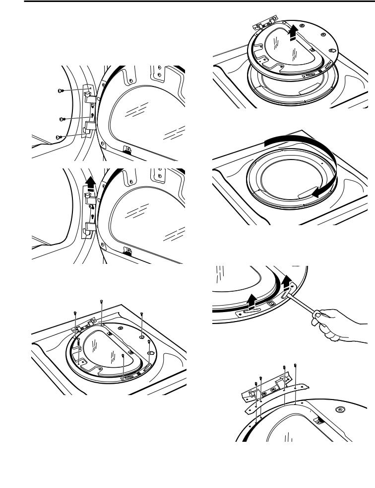
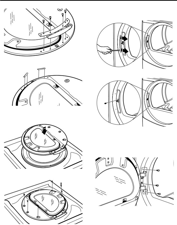
Remove the Door Assembly
1.Place a towel or soft cloth on top of dryer or work space to avoid scratching of the surface.
2.Remove 3 of the 4 screws that hold the door hinge on the front panel of the dryer. Partially loosen the remaining screw with keyhole opening and lift the door off the screw.
3.Lay the door assembly on a previously prepared flat surface with the inside (inner door assembly) facing up, and remove 6 phillips-head screws to release outer door assembly from inner door assembly.
NOTE: It is important that you remove only 6 indicated screws.
4. Lift the inner door assembly off outer door assembly.
5. Rotate outer door 180°.
Reverse Hinge
1.Use a small flat-blade screwdriver to remove 2 plug strips from the inner door. Slide the head of the screwdriver under the plugs, without scratching inner door surface, and lift up strip.
2. Remove the 4 screws that attach to inner door hinge.
24
REVERSING DRYER DOOR SWING
3. Move hinge to other side. Reinstall 4 screws.
4. Reinstall plug strips on opposite side of the inner door.
5. Check for fingerprints on the glass. Clean if necessary.
Replace the Door Assembly
1. Place the inner door assembly inside the outer door assembly.
2.Reassemble the inner and outer door assemblies with the 6 screws.
Reverse the strike
1.Use a small flat-blade screwdriver to remove plug strip from the dryer door opening. Slide the head of the screwdriver under the plugs, without scratching dryer surface, and lift up strip.
2. Remove the strike using a Phillips screwdriver.
3. Insert strike on the opposite side.
Reinstall the door
1.Partially insert the third screw from the top; then slide the hinge onto this screw while hooking the hinge into the front
panel hole. Reattach door to dryer front panel with the remaining three screws.
2.Check for fingerprints on the glass. Clean if necessary.
3.Close door and check that it latches securely.
25
STACKED WASHER/DRYER MAINTENANCE INSTRUCTIONS
Washer
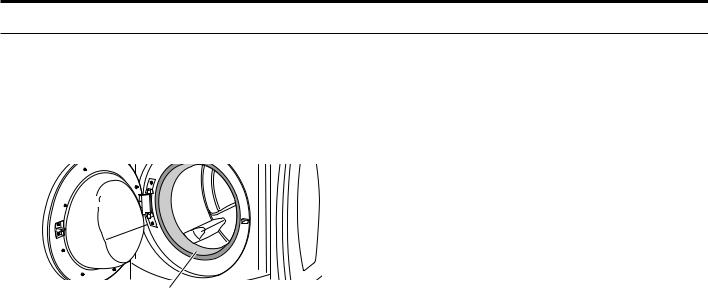
Cleaning the Door Seal/Bellow
1.Open the washer door and remove any clothing or items from the washer.
2.Inspect inner glass door. If debris is present, wipe it off using a damp cloth.
3.Inspect the colored seal/bellow between the door opening and the basket for stained areas. Pull back the seal/bellow to inspect all areas under the seal/bellow and to check for foreign objects.
Seal/Bellow
4.If stained areas are found, wipe down these areas of the seal/ bellow:
a)Mix a dilute solution, using 177 mL (3/4 cup) of liquid chlorine bleach, and 3.8 L (1 gal.) of warm tap water.
b)Wipe the seal/bellow area with the dilute solution, using a damp cloth.
c)Let stand 5 minutes.
d)Wipe down area thoroughly with a dry cloth and let the washer interior air dry with door open.
IMPORTANT:
νWear rubber gloves when cleaning for prolonged periods.
νRefer to the bleach manufacturer’s instructions for proper use.
To clean washer interior:
1.Open the washer door and remove any clothing or items from the washer.
2.Use liquid chlorine bleach:
Open the dispenser drawer and immediately add
160 mL (2/3 cup) of liquid chlorine bleach to the bleach compartment.
NOTE: Do not add any detergent. Use of more than 160 mL (2/3 cup) of bleach will cause product damage over time.
3.Close the washer door and the dispenser drawer.
4.To start the Washer Cleanout cycle, first enter “Service Mode.” Then press and hold the lower-right (QUICK CYCLE) button for 2 seconds. With the entire display flashing, press the centerright (BRIGHTS) button.
To exit out of the service mode and activate the clean wash cycle, push the BRIGHTS button, then turn the key.
NOTE: The door will lock, the basket will rotate 1/2 turn, then the door will unlock and lock again, then the Washer Cleanout Cycle will continue.
νThe washer will not fill, but the basket will rotate while the washer runs a short sensing cycle. This will take approximately 3 minutes.
5.The cycle will determine whether clothing or other items are in the washer.
a) If no items are detected in the washer, it will proceed to Step 7.
b) If any items are detected in the washer, “F-34” will be displayed. Then the door will unlock.
νEnter the service mode and then press and hold the lower-right (QUICK CYCLE) button to cancel the failure code. Then repeat steps 1, 3, and 4 to start the cycle again.
Maintenance Instructions:
This washer has a special cycle that uses higher water volumes in combination with liquid chlorine bleach to thoroughly clean the inside of the washer.
NOTES:
νRead these instructions completely before beginning the cleaning process.
νIf necessary, the cleaning cycle may be interrupted by pressing the lower-right (QUICK CYCLE) button twice. However, this will not immediately stop the cycle. The washer will continue with several rinse and drain steps to ensure that all remaining bleach is rinsed from the washer.
6.Once the cycle has begun, allow the cycle to complete.
7.After the cycle is complete, leave the door open slightly to allow for better ventilation and drying of washer interior.
26

STACKED WASHER/DRYER MAINTENANCE INSTRUCTIONS
Washer
Always do the following to maintain washer freshness:
νUse only HE High Efficiency detergent.
νLeave the door slightly open after each cycle to allow for better ventilation and drying of washer interior.
νClean the washer monthly using the Washer Maintenance Procedure, using 160 mL (2/3 cup) of liquid chlorine bleach.
νIf the procedure does not sufficiently improve the washer freshness, please evaluate your installation and usage conditions for other causes.
Cleaning the exterior
Use a soft damp cloth or sponge to wipe up any spills. Occasionally wipe the outside of your washer to keep it looking new. Use mild soap and water. Do not use abrasive products.
Cleaning the dispenser drawer
The dispenser drawer is removable for easy cleaning.
1.Unlock the dispenser drawer for removal by inserting a flat-blade screwdriver into the catch release. Remove the dispenser drawer.
2.Remove the inserts (the siphon from the softener and bleach compartments).
3.Wash the parts under running water.
NOTE: Do not wash components in the dishwasher.
4.Replace the inserts and return the dispenser to the drawer.
Water inlet hoses
Replace the inlet hoses after 5 years of use to reduce the risk of hose failure. Periodically inspect and replace inlet hoses if bulges, kinks, cuts, wear, or leaks are found.
When replacing your inlet hoses, record the date of replacement.
Dryer
Maintenance instructions:
•Clean lint screen before and after each cycle.
•Removing accumulated lint:
From inside the dryer cabinet:
Lint should be removed every 2 years or more often, depending on dryer usage. Cleaning should be done by a qualified person.
From the exhaust vent:
Lint should be removed every 2 years, or more often, depending on dryer usage.
•Keep area around dryer clear and free from combustible materials, gasoline and other flammable vapors and liquids.
•Keep dryer area clear and free from items that would obstruct the flow of combustion and ventilation air.
If dryer does not operate, check the following:
•Electrical supply is connected.
•Circuit breaker is not tripped or house fuse is not blown.
•Door is closed. Listen closely to hear the door switch activate.
•Cycle selection button has been pushed firmly.
•For gas dryers, check that gas supply shut-off valves are set in open position.
IF YOU NEED ASSISTANCE
If you need help, contact the dealer from whom you purchased the appliance, or a Maytag designated service company. When calling, please know the purchase date and the complete model and serial number of your appliance. This information will help us to better respond to your request.
Accessories
Enhance your washer/dryer with these premium accessories.
For more high-quality items or to order, contact your authorized Maytag distributor.
Part Number |
Accessory |
|
|
8212526 |
Washer drip trays; fits under all |
31682 |
All-purpose appliance cleaner |
|
|
1903WH |
Laundry supply storage cart |
Whirlpool Corporation, Benton Harbor, Michigan 49022, U.S.A. Manufacturer site: Whirlpool Mexico S.A. de C.V.,
Antigua Carretera a Roma Km 9, Col.
El Milagro, Apodaca, Nuevo Leon, C.P. 66634, Mexico. EU representative: Maytag UK Ltd, Redhill, RH1 1AX, UK BAUKNECHT HAUSERGRÄTE Gmb H, D-73614 Schorndorf
27

TECHNICAL SPECIFICATIONS – GAS DRYER
28
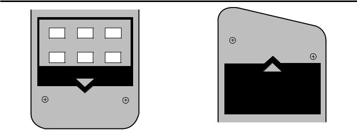
ELECTRONIC CONTROL SETUP INSTRUCTIONS
WHITES COLORS BRIGHTS
PERM. DELICATES QUICK
PRESS AND KNITS CYCLE
WASHER
Washer Control
NOTE: After the washer/dryer has been installed and plugged in, the display will show “0 MINUTES” on the washer and dryer portions of the display. After the washer and dryer doors have been opened and closed, the display will show the price for each
machine. On washer/dryers set for free cycles, the display sections will flash “SELECT CYCLE.”
1.PD Models: Insert coins until “SELECT CYCLE” flashes on the display portion of the washer or dryer that is to be run.
PN Models: A debit card is required rather than coins. Generation 1 or 2 debit card systems may be used; but when the Generation 2 debit system is used, the controls will automatically be set to Enhanced Debit mode (J. Ed). In
Enhanced Debit mode, the card balance will also display when a debit card is inserted into the reader.
2.Door must be closed on the desired washer/dryer before cycle selection is made.
3.Press the fabric setting button for the washer/dryer cycle desired. After the cycle is started, the time will display and count down.
4.If a cycle is interrupted by opening the door or power loss, “RESELECT CYCLE” will flash in the display. To restart the washer/dryer, close door and reselect desired cycle.
NOTE: When set for free vend operation an ongoing dryer cycle will cancel if the door is opened.
|
|
|
DRYER |
||||
|
|
|
|
|
|
|
|
WHITES |
PERM. |
||||||
& COLORS |
PRESS DELICATES |
||||||
|
|
|
|
|
|
|
|
|
|
|
|
|
|
|
|
Dryer Control
General Washer/Dryer User Information
SCROLLING “OUT OF ORDER” MESSAGE, FOLLOWED BY A FAILURE OR DIAGNOSTIC CODE, SHOWING IN DISPLAY – This condition indicates the washer/dryer is inoperative. Diagnostic codes being displayed on the upper portion of the display pertain to the dryer section, and diagnostic codes displayed on the lower portion of the display apply to the washer section. Diagnostic codes displayed on both the upper and lower portions of the display pertain to the control system of both the washer and dryer.
“0 MINUTES” SHOWING IN DISPLAY – This indicates the cycle is complete and the washer/dryer cannot be operated. Coins dropped or debit inputs during this condition will be stored in escrow but cannot be used until normal operation is restored by opening and closing the door. If a door switch has failed, causing “0 MINUTES” to remain in the display after the door is opened and closed, it must be replaced before normal operation can be restored.
COLD START (Initial first use) – Washer/dryer is programmed at the factory as follows:
Washer |
11-minute wash period |
|
1.75 wash price (PD models) |
|
0.00 wash price (PN models) |
|
3 rinses (extra rinse not enabled) |
Dryer |
5 minutes per coin for PD models |
|
45 minutes dry time for PN models |
|
1.50 dry price (fixed cycle with top off – PD |
|
Models) |
|
0.00 dry price (fixed cycle – PN Models) |
29

ELECTRONIC CONTROL SETUP INSTRUCTIONS
WARM START (after power failure) – A few seconds after power is restored, if a cycle was in progress at the time of the power failure, “RESELECT CYCLE” will flash in the display, indicating the need for a key press to restart washer or dryer.
WASHER DOOR LOCK – Prior to beginning a cycle, there is a door lock routine of lock/unlock/relock, then cycle begins. The door will remain locked until the end of a cycle or approximately 2 minutes after a power interruption.
PRICING – After the door is opened and then closed following the completion of a cycle, the display indicates the cycle price (unless set for free operation, where the display will flash “SELECT CYCLE”). As coins are dropped or debit inputs arrive, the display will change to lead the user through the initiation of a cycle.
There are four (4) types of dryer pricing:
Fixed “Vend” Pricing
A dryer setup for “Fixed Cycle” operation can only accept additional time accumulated by increments equal to the length of a complete dry cycle. A maximum of 99 minutes may be purchased; no additional credit is given for coins dropped with 99 minutes in the display.
Accumulator Pricing
If the price is set to one coin 1, then accumulator pricing is in effect. Cycle time can be purchased one coin at a time (PD models) up to the maximum time of 99 minutes.
Fixed Cycle With Top Off Pricing
A dryer set to offer “Top Off” capability will allow time to be added to an existing dry cycle in increments equal to the number of minutes of dry time per coin (coin 1), up to 99 minutes, regardless of the cost required to start the dryer. No credit is given for coins or debit inputs entered when the control is displaying 99 minutes.
PN Models: In Enhanced Debit Mode, the top off price can be set independently (see VALUE OF COIN 2), and the top off time is calculated according to the following equation:
top off time = |
top off price |
x full cycle length |
|
|
|||
full cycle price |
|||
|
|
Penny increment offset is not applied to top off purchases.
FREE CYCLES – This is established by setting the cycle price to zero. When this happens, “SELECT CYCLE” will appear rather than a cycle price. Any cycle started as a free cycle
will automatically terminate when the door is opened.
DEBIT CARD READY – This washer/dryer is debit card ready. It will accept a variety of debit card systems, but does NOT come with a debit card reader. Refer to the debit card reader
manufacturer for proper washer/dryer setup. In models converted to a Generation 1 debit card system, debit pulses represent the equivalent of one coin (coin 1).
Control Set-up Procedures
IMPORTANT: Read all instructions before operating.
PD/PN Models: Insert service switch key and turn counterclockwise.
PN Models: Once a Generation 2 debit card reader is installed (according to the reader manufacturer’s instructions), the set-up modes can only be changed by inserting a set-up card (supplied by the reader manufacturer) into the card slot. Inserting the service switch key and turning will only allow access to the service mode.
The washer/dryer is now in the set-up mode. The lower fabric setting buttons and the lower portion of the display are used to set up the digital control for the washer. The upper three fabric setting buttons and the upper portion of the display are used to set up the controls for the dryer.
The display can contain 4 numbers and/or letters and a decimal point on both the top and bottom display portions. These are used to indicate the set-up codes and related code values available for use in programming the washer/dryer.
How to Use the Buttons to Program the Controls
1.The lower-left (PERM. PRESS) button is used to adjust the values associated with washer set-up codes and the upper-left (WHITES & COLORS) button is for the dryer. Pressing the button will change the value by increments. Rapid adjustment is possible by holding the button down.
2.The lower-middle (DELICATES AND KNITS) button will advance through the set-up codes. Pressing the button will advance both the washer and dryer to the next available set-up code. Some set-up codes are washeror dryer-specific and will not be displayed on both the washer and dryer portions of the display. Holding down the lower-middle (DELICATES AND KNITS) button will automatically advance through the set-up codes
at a rate faster than 1 per second.
3.The lower-right (QUICK CYCLE) button is used to select or deselect washer options; upper-right (DELICATES) is used for dryer option selection or deselection.
30
 Loading...