


MLG24PDAGW2
Maytag MLG24PDAGW2, MLG24PNAGW0, MLG24PNAGW1, MLG24PDAGW3, MLG24PDAGW4 Installation Guide
...
iNSTALLATiON iNSTRUCTiONS COMMERCIAL DRYER
Gas
iNSTRUCTiONS POUR L'INSTALLATION
D'UN SECHE-LINGE COMMERCIAL
A gaz
INSTRUCCIONES DE INSTALACION SECADORA COMERClAL
A gas
ISTRUZIONI DI INSTALLAZIONE
ASCIUGATRICE COMMERCIALE
A gas
MLG24PD
MLG24PN
www.maytagcom merciaNaundw.com
W10184555A
TABLEOF CONTENTS
DRYER SAFETY ............................................................................ 3
DRYER DISPOSAL ........................................................................ 4
INSTALLATION REQUIREMENTS .............................................. 4
Tools and Parts .......................................................................... 4
Location Requirements .............................................................. 4
Electrical Requirements - Gas Dryer .......................................... 6
Gas Supply Requirements ........................................................ 6
Venting Requirements ................................................................ 7
TABLEDES
INSTALLATION INSTRUCTIONS - GAS DRYER .................... 9
Install Leveling Legs .................................................................... 9
Make Gas Connection ................................................................ 9
Connect Vent .............................................................................. 9
Complete Installation ................................................................ 9
ELECTRONIC CONTROLS SETUP ......................................... 10
MAINTENANCE INSTRUCTIONS .......................................... 10
REVERSING THE DOOR SWING (OPTIONAL) ...................... 10
TECHNICAL SPECIFICATIONS - GAS DRYER ...................... 11
WARRANTY .............................................................................. 12
MATIERES
SECURITE DU SECHE-MNGE ................................................ 13
ELIMINATION DU SECHE-MNGE .......................................... 14
EXIGENCES D'INSTALLATION ................................................ 14
Outillage et pi_ces .................................................................... 14
Exigences d'emplacement ...................................................... 15
Specifications electriques - seche-tinge h gaz ......................... 16
Specifications de I'alimentation en gaz .................................. 17
Exigences concemant revacuation .......................................... 18
INSTRUCTIONS D'INSTALLATION -
SECHE-LINGE A GAZ .............................................................. 19
Installation des pieds de nivellement ........................................ 19
Raccordement h la canalisation de gaz .................................. 20
Raccordement du conduit d'evacuation ................................ 20
Achever I'instatlation ................................................................ 20
REGLAGE DE LA COMMANDE ELECTRONIQUE ................. 20
INSTRUCTIONS D'ENTRETIEN ............................................. 21
INVERSION DU SENS D'OUVERTURE
DE LA PORTE (FACULTAT_F) ................................................... 21
FICHE TECHNIQUE - SECHE-LINGE A GAZ ........................ 22
GARANTIE ................................................................................ 23
P
INDICE
SEGURIDAD DE LA SECADORA ............................................ 24
ELIMINACKSN DE LA SECADORA .......................................... 25
REQUISITOS DE INSTALACl6N ............................................ 25
Piezas y herramientas .......................................................... 25
Requisitos de ubicaci6n ........................................................ 25
Requisitos electrtcos - secadora a gas ................................ 27
Requisitos del suministro de gas ............................................ 27
Requisitos de ventilaci6n .................................................... 28
INSTRUCCIONES DE INSTALACION -
SECADORA A GAS ................................................................ 30
InstataciSn de las paras niveladoras .................................... 30
Conexi6n del suministro de gas ............................................ 30
Conexi6n del ducto de escape ............................................ 30
Complete la instataci6n ........................................................ 31
PREPARAClON DEL CONTROL ELECTR6NICO ................. 31
INSTRUCClONES DE MANTENIMIENTO ............................. 31
COMO INVERTIR EL SENTIDO DE ABERTURA
DE LA PUERTA (OPCIONAL) ................................................. 32
ESPEClFICAClONES TI_CNlCAS - SECADORA A GAS ......33
GARANTIA ................................................................................ 34
INDICE
SICUREZZA DELL'ASClUGATRICE ........................................ 35
L'EUMINAZ_ONE DELUASClUGATRICE .................................. 36
REQUIS_TI D'INSTALLAZIONE ................................................ 36
Attrezzi e componenti .............................................................. 36
Requisiti di ubicazione ............................................................ 36
Requisiti elettrici - asciugatrice a gas .................................... 38
Requisiti di alimentazione det gas ............................................ 38
Requisiti di scarico .............................................................. 39
ISTRUZIONI DI INSTALLAZIONE- ASClUGATRlCE
A GAS ...................................................................................... 41
Instatlazione dei piedini di regolazione .................................... 41
Eseguire il colleganento gas .................................................... 41
Connessione delto scarico ...................................................... 41
Completamento dell'instattazione ............................................ 41
IMPOSTAZIONI COMANDI ELETTRONlCl ............................ 42
ISTRUZIONI DI MANUTENZIONE ......................................... 42
INVERTIRE LA ROTAZIONE DI APERTURA
(OPZIONALE) .......................................................................... 43
DATI TECNICl - ASCIUGATRICE A GAS .............................. 43
GARANZIA ................................................................................ 44
DRYERSAFETY
Your safety and the safety of others are very important.
We have provided many important safety messages in this manual and on your appliance. Always read and obey all safety
messages.
This is the safety alert symbol.
This symbol alerts you to potential hazards that can kill or hurt you and others.
All safety messages will follow the safety alert symbol and either the word "DANGER" or "WARNING."
These words mean:
You can be killed or seriously injured if you don't immediately
follow instructions.
You can be killed or seriously injured if you don't follow
instructions.
All safety messages will tell you what the potential hazard is, tell you how to reduce the chance of injury, and tell you what can
happen if the instructions are not followed.
FOR YOUR SAFETY
1. Do not use or store petrol or other flammable materials in this appliance or near th{s appliance.
2. Do not spray aerosols in the vicinity of this appliance while it is in operation.
3. Do not modify this appliance.
WARNING: For your safety, the information in this manual must be followed to minimize
the risk of fire or explosion, or to prevent property damage, personal injury, or death.
- Do not store or use petrol or other flammable vapors and liquids in the vicinity of this
or any other appliance.
-WHAT TO DO {F YOU SMELL GAS:
® Do not try to light any appliance.
® Do not touch any electrical switch; do not use any phone in your building.
® Clear the room, building, or area of all occupants.
® immediately call your gas supplier from a neighbor's phone. Follow the gas supplier's
instructions.
® if you cannot reach your gas supplier, call the fire department.
- {nstallation and service must be performed by a qualified installer, service agency, or
the gas supplier.
3
DRYERDISPOSAL
This appliance is marked according to the European directive 2002/96/EC on Waste Electrical and Electronic Equipment
(WEEE).
By ensuring this product is disposed of correctly, you will help avoid potential negative consequences for the environment and
human health, which could otherwise be caused by inappropriate waste handling of this product.
The symbol on the product, or on the documents accompanying the product, indicates that this appliance may not be treated
as household waste. Instead it shall be handed over to the applicable collection point for the recycling of electrical and
electronic equipment.
Disposal must be carried out in accordance with local environmental regulations for waste disposal.
For more detailed information about treatment, recovery and recycling of this product, please contact your local city office, your
household waste disposal service or the shop where you purchased the product.
INSTALLATIONREQUIREMENTS
Gather the required tools and parts before starting installation.
Read and follow the instructions provided with any tools
listed here.
Tools needed
m 20 cm (8") or 25 cm (10") [] 8 mm (s/16")socket wrench
Pipe wrench [] Utility knife
[] 20 cm (8") or 25 cm (10") [] Vent clamps
adjustable wrench
[] Pipe-joint compound
[] Flat-blade screwdriver resistant to LP gas
[] Phillips screwdriver [] Sealing compound gun
[] Adjustable wrench that and sealing compound (for
opens to 25 mm (1") or installing new exhaust vent)
hex-head socket wrench [] Pliers
[] Level [] Putty knife
Parts supplied
Remove parts bag from dryer drum. Check that all parts were
included.
[] Foot boot (4)
[] Dryer foot (4)
NOTE: The circuit diagram for this machine is located inside the
lower front panel.
Explosion Hazard
Keep flammable materials and vapors, such as petrol,
away from dryer.
Do not install in a garage.
Failure to do so can result in death, explosion, or fire.
If installing a gas dryer:
IMPORTANT: Observe all governing codes and ordinances.
[] Check code requirements: Some codes limit or do not permit
installation of clothes dryers in garages or sleeping quarters.
Contact your local building inspector.
[] Make sure that lower edges of the cabinet, plus the back and
bottom sides of the dryer, are free of obstructions to permit
adequate clearance of air openings for combustion air. See
"Recessed Area Installation Instructions" below
for minimum spacing requirements.
[] Do not install on carpet.
NOTE: The dryer must not be installed in an area where it will be
exposed to water and/or weather.
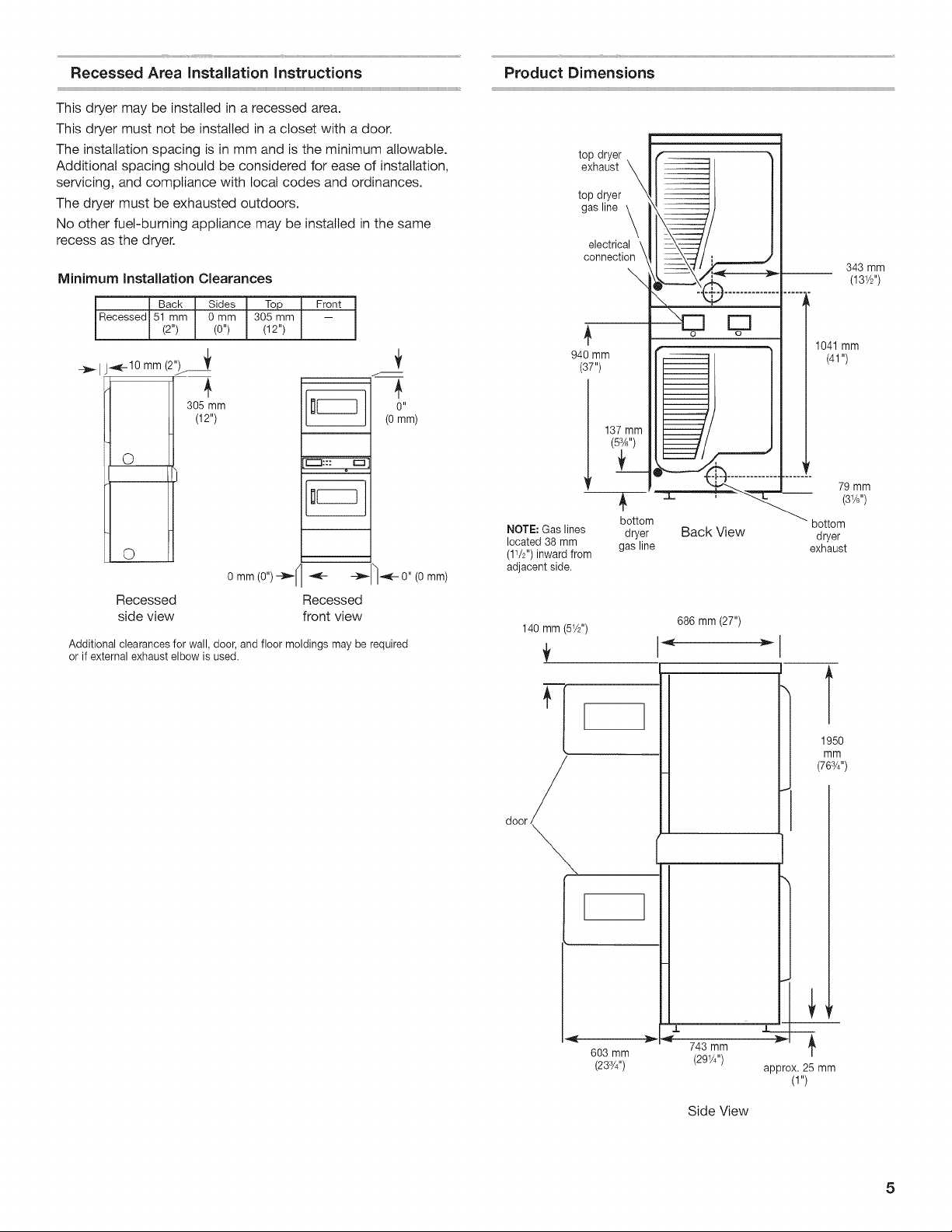
Recessed Area installation instructions
This dryer may be installed in a recessed area.
This dryer must not be installed in a closet with a door.
The installation spacing is in mm and is the minimum allowable.
Additional spacing should be considered for ease of installation,
servicing, and compliance with local codes and ordinances.
The dryer must be exhausted outdoors.
No other fuel-burning appliance may be installed in the same
recess as the dryer.
Minimum Installation Clearances
Back Sides Top { Front I
{Recessed{51 mm { 0mm I 305mm { -- I
(2") (0") (12")
__ I J_-10 mm (2")f _
3o5mm
(12")
O
O
7
0 II
(0 mm)
[[--1::: o _-1
ix,
o mm(o")_ _ o" (o mm)
Recessed Recessed
side view front view
Additional clearances for wall, door, and floor moldings may be required
or if external exhaust elbow is used.
Product Dimensions
top dryer
exhaust _
top dryer
gas line _
electrical \
connection
\,
940 mm
(37")
137 mm
11;
NOTE: Gas lines
located 38 mm
(11/2'') inward from
adjacent side.
O O
bottom
dryer Back View
gas line
343 mm
(131/2'')
1041 mm
(41 ")
79 mm
(31/8'')
bottom
dryer
exhaust
140 mm (51/2'')
door
603 mm
(233/4'')
686 mm (27")
J.
743 mm
(291/4'')
T
1950
mm
(763/4'')
l
approx. 25 mm
(1")
Side View
5
Important: Observe all governing codes and ordinances.
This dryer is supplied/fitted with an electricity supply cord and
plug. It should be connected to electricity supply socket at the
voltage shown on the rating plate. The minimum supply fuse
capacity should be 5A. The dryer must be positioned so that the
plug is accessible. If the fitted plug is not used, the electrical
connection must be carried out by a competent electrician in
accordance with local or national codes.
If the supply cord is damaged, it must be replaced with a
specially terminated cord by an authorized service agent or a
similarly competent person in order to avoid a hazard.
Do not use an adapter.
Do not use an extension cord.
Electric Shock Hazard
This is a 3=wire appliance which must be earthed.
Do not earth to a gas pipe.
Do not change the power supply cord plug. if it does
not fit the outlet, have a proper outlet installed by a
qualified electrician.
Do not use an extension cord with this dryer.
Failure to follow these instructions could result in
death, fire, or serious injury.
If codes permit and an additional earth bond wire is used, it is
recommended that a qualified electrician determine that the earth
bond path is adequate.
EARTHING INSTRUCTIONS
[] For an earthed cord-connected dryer:
This dryer must be earthed. In the event of a malfunction or
breakdown, grounding will reduce the risk of electric shock
by providing a path of least resistance for electric current.
This dryer is equipped with a cord having an equipment-
earthing conductor and a earthing plug. The plug must be
plugged into an appropriate outlet that is properly instaled
and earthed in accordance with all local codes and
ordinances.
WARNING: Improper connection of the equipment=
earthing conductor can result in a risk of electric shock.
Check with a qualified electrician or service representative
or personnel if you are in doubt as to whether the dryer
is properly earthed. Do not modify the plug provided
with the dryer: if it will not fit the outlet, have a proper
outlet installed by a qualified electrician.
SAVE THESE INSTRUCTIONS
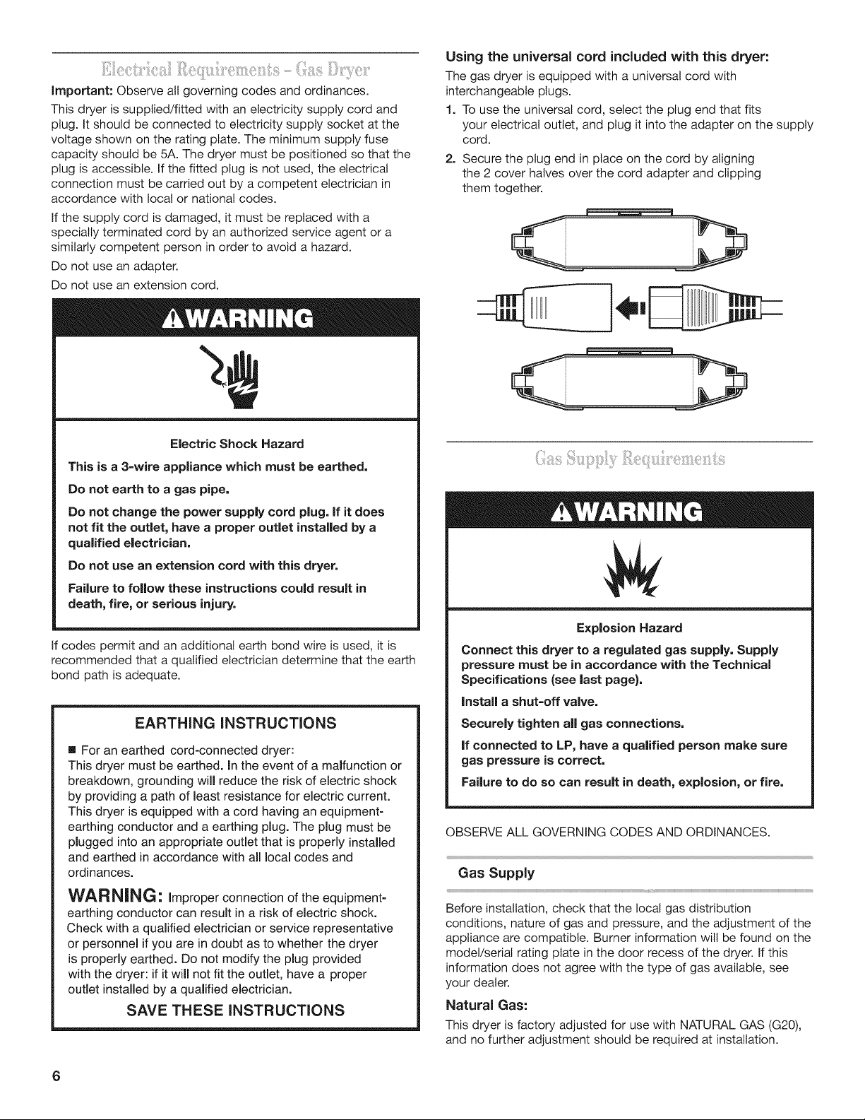
Using the universal cord included with this dryer:
The gas dryer is equipped with a universal cord with
interchangeable plugs.
1. To use the universal cord, select the plug end that fits
your electrical outlet, and plug it into the adapter on the supply
cord.
2. Secure the plug end in place on the cord by aligning
the 2 cover halves over the cord adapter and clipping
them together.
Explosion Hazard
Connect this dryer to a regulated gas supply. Supply
pressure must be in accordance with the Technical
Specifications (see last page}.
Instal a shut=off valve.
Securely tighten all gas connections.
If connected to LP, have a qualified person make sure
gas pressure is correct.
Failure to do so can result in death, explosion, or fire.
OBSERVE ALL GOVERNING CODES AND ORDINANCES.
Gas Supply
Before installation, check that the local gas distribution
conditions, nature of gas and pressure, and the adjustment of the
appliance are compatible. Burner information will be found on the
model/serial rating plate in the door recess of the dryer. If this
information does not agree with the type of gas available, see
your dealer.
Natural Gas:
This dryer is factory adjusted for use with NATURAL GAS (G20),
and no further adjustment should be required at installation.

L.P. Gas:
This dryer is also certified for use with L.R (propane or butane)
gases with appropriate conversion. No attempt shall be made to
convert the appliance from the gas specified on the model/serial
rating plate for use with a different gas without consulting the
serving gas supplier.
Conversion must be done by a competent service technician.
Gas conversion kit, part number 279918, is available for purchase
from your dealer. Full instructions are supplied with the kit.
Supply line requirements:
Provide a rigid gas supply line to the dryer location. It should be
minimum 12.5 mm (1/2") ID. When acceptable to the gas supplier
and local codes, 10 mm (3/8") ID rigid supply line may be used
for lengths under 6.1 m (20'). Pipe-joint compounds resistant to
the action of LR gas must be used.
Gas connection to the dryer itself should be made by means of a
flexible gas hose suitable for the appliance and gas category in
accordance with national installation regulations. If in doubt,
contact the gas supplier. It should be minimum 10 mm (3/8") ID.
A means of restraint should be used between the appliance and
the wall to prevent straining of the rigid gas supply when the
appliance is moved. An appropriate length of chain and a watt
hook is recommended.
The dryer gas inlet connection is a 3/8" NPT thread. An adapter is
supplied for conversion to standard ISO.228-1 thread (3/8" BSP).
Check for leaks by using an approved noncorrosive leak-
detection solution. Bubbles will show a leak. Correct any leak
found. A pressure measurement tapping is provided on the
gas valve within the dryer, accessible after removal of the lower
front panel.
The dryer must be disconnected from the gas supply piping
system during any pressure testing of that system.
Fire Hazard
Use a heavy metal vent.
Do not use a plastic vent.
Do not use a metal foil vent.
Failure to follow these instructions can result in death
or fire.
[] The design of the flue system should be such that any
condensate formed when operating the dryer from cold shall
either be retained and subsequently re-evaporated or
discharged.
[] The dryer vent must not be discharged into a flue which
is used for exhausting fumes from appliances burning gas or
other fuels, chimney, wall, ceiling, or a concealed space of a
building, or any other vent used for venting.
[] Do not use an exhaust hood with a magnetic latch.
[] Do not install flexible metal vent in enclosed walls, ceilings,
or floors.
[] 102 mm (4") heavy metal vent and clamps must be used.
[] Use clamps to seat all joints. Vent must not be connected
or secured with screws or other fastening devices which
extend into the interior of the vent. Do not use duct tape.
iMPORTANT: Observe all governing codes and ordinances.
Use a heavy metal vent. Do not use plastic or metal foil vent.
Rigid metal vent is recommended to prevent crushing
and kinking.
Flexible metal vent must be fully extended and supported when
the dryer is in its final position. Remove excess flexible metal vent
to avoid sagging and kinking that may result in reduced airflow
and poor performance.
An exhaust hood should cap the vent to prevent rodents and
insects from entering the home or business.
Exhaust hood must be at least 305 mm (12") from the ground
or any object that may be in the path of the exhaust (such as
flowers, rocks, or bushes).
If using an existing vent system, clean lint from the entire length
of the system and make sure exhaust hood is not plugged with
lint. Replace any plastic or metal foil vent with rigid metal or
flexible metal vent.
Plan installation to use the fewest number of elbows and turns.
Exhaust Air Flow
A. Good
B. Better
Allow as much room as possible when using elbows or making
turns. Bend vent gradually to avoid kinking.
Vent outlet is located at the center of the bottom dryer back.
The vent can be routed up, down, left, right, behind the dryer
or straight out the back of the dryer.
WARNING; To reduce the risk of fire, this dryer MUST BE
EXHAUSTED OUTDOORS.
[] Adequate ventilation has to be provided to avoid the backflow
of gases into the room from other fuel-burning appliances,
including open fires (i.e. available airflow into the room should
match airflow out from the room).
7
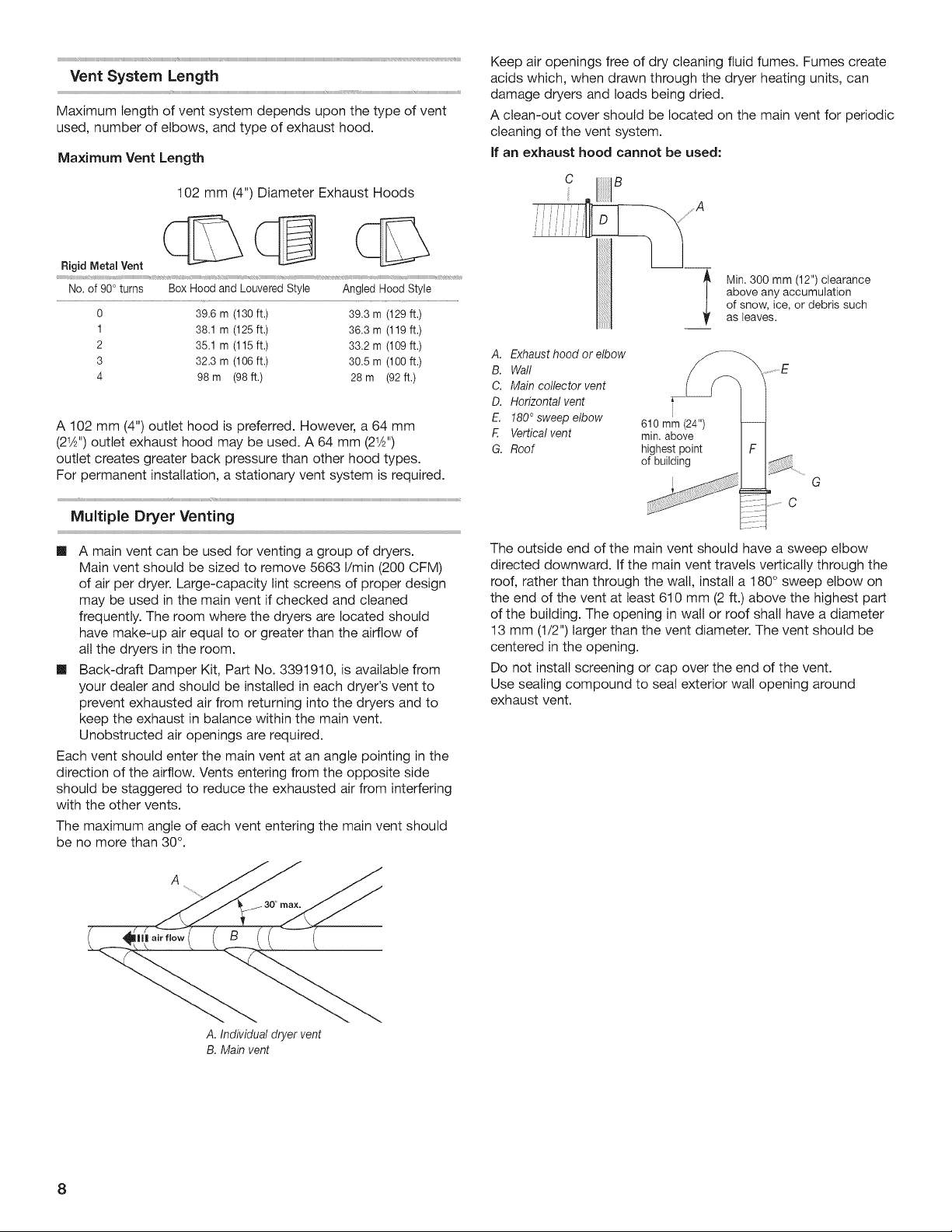
Vent System Length
Maximum length of vent system depends upon the type of vent
used, number of elbows, and type of exhaust hood.
Maximum Vent Length
102 mm (4") Diameter Exhaust Hoods
Rigid Metal Vent _
t 1 i
No. of 90° turns Box Hood and Louvered Style Angled Hood Style
9 39.6 m (130 ft.) 39.3 m (129 ft.)
1 38.1 m (125 ft.) 36.3 m (119 ft.)
2 35.1 m (115 ft.) 33.2 m (199 ft.)
3 32.3 m (106 ft.) 30.5 m (100 ft.)
4 98 m (98 ft.) 28 m (92 ft.)
A 102 mm (4") outlet hood is preferred. However, a 64 mm
(21_'') outlet exhaust hood may be used. A 64 mm (21_'')
outlet creates greater back pressure than other hood types.
For permanent installation, a stationary vent system is required.
Multiple Dryer Venting
[] A main vent can be used for venting a group of dryers.
Main vent should be sized to remove 5663 I/min (200 CFM)
of air per dryer. Large-capacity lint screens of proper design
may be used in the main vent if checked and cleaned
frequently. The room where the dryers are located should
have make-up air equal to or greater than the airflow of
all the dryers in the room.
[] Back-draft Damper Kit, Part No. 3391910, is available from
your dealer and should be installed in each dryer's vent to
prevent exhausted air from returning into the dryers and to
keep the exhaust in balance within the main vent.
Unobstructed air openings are required.
Each vent should enter the main vent at an angle pointing in the
direction of the airflow. Vents entering from the opposite side
should be staggered to reduce the exhausted air from interfering
with the other vents.
The maximum angle of each vent entering the main vent should
be no more than 30°.
A.Individualdryervent
B. Mainvent
Keep air openings free of dry cleaning fluid fumes. Fumes create
acids which, when drawn through the dryer heating units, can
damage dryers and loads being dried.
A clean-out cover should be located on the main vent for periodic
cleaning of the vent system.
If an exhaust hood cannot be used:
A. Exhaust hood or elbow
B. Waft
C. Main collector vent
D. Horizontal vent
E. 180° sweep elbow
E Vertical vent
G. Roof
610 mm(24")
min. above
highestpoint
of building
Min. 300 mm (12") clearance
above any accumulation
of snow, ice, or debris such
as {eaves.
G
C
The outside end of the main vent should have a sweep elbow
directed downward. If the main vent travels vertically through the
roof, rather than through the walt, install a 180° sweep elbow on
the end of the vent at least 610 mm (2 ft.) above the highest part
of the building. The opening in wall or roof shall have a diameter
13 mm (1/2") larger than the vent diameter. The vent should be
centered in the opening.
Do not install screening or cap over the end of the vent.
Use sealing compound to seat exterior walt opening around
exhaust vent.

INSTALLATIONINSTRUCTIONS- GASDRYER
¸iijj
Excessive Weight Hazard
Use two or more people to move and install dryer.
Failure to do so can result in back or other injury.
NOTE: Slide dryer onto cardboard or hardboard before moving to
avoid damaging floor covering.
1. Using two or more people, move dryer to desired installation
location.
2. Take tape off front corners of dryer. Open dryer and remove
the literature and parts packages. Wipe the interior of the
drum thoroughly with a damp cloth.
3. Take two of the cardboard corners from the carton and place
them on the floor in back of the dryer. Firmly grasp the body of
the dryer and gently lay it on its back on the cardboard corners.
4. With one of the legs in hand, check the ridges for a diamond
marking. That's how far the leg is supposed to go into the hole.
5. Start to screw the leveling legs into the holes by hand. (Use
a small amount of liquid detergent to lubricate the screw
threads so it is easier to turn the legs.) Use a 1" (25 mm)
wrench or socket wrench to finish turning the legs until you
reach the diamond mark. Then fit a protective foot boot over
each foot.
Now stand the dryer up.
6. Remove cardboard or hardboard from under dryer. Adjust the
legs of the dryer up or down until the dryer is level.
Excessive Weight Hazard
Use two or more people to move and install dryer.
Failure to do so can result in back or other injury.
1. Remove red cap from gas pipe.
2. Connect gas supply to dryer. If the flexible gas hose has 3/8"
BSP thread, use the supplied conversion thread adapter. Use
pipe-joint compound resistant to the action of LR gas for gas
connections.
If necessary for service, open the toe panel. Use a putty knife
to press on the 2 toe panel locks located at the top of the toe
panel. Pull downward on the toe panel to open. Toe panel is
hinged at the bottom.
3. Open the shutoff valve in the gas supply line.
4. Test all connections by brushing on an approved noncorrosive
leak-detection solution. Bubbles will show a leak. Correct any
leak found.
1. Using a 102 mm (4") clamp, connect vent to exhaust outlet
in dryer. If connecting to existing vent, make sure the vent is
clean. The dryer vent must fit over the dryer exhaust outlet
and inside the exhaust hood. Make sure the vent is secured
to exhaust hood with a 102 mm (4") clamp.
1. Move dryer into final position. Do not crush or kink vent. Make
sure dryer is level.
2. Check to be sure there are no kinks in the flexible gas line.
3. With dryer in final position, place level on top of the dryer, first
side to side; then front to back. If the dryer is not level, adjust
the legs of the dryer up or down until the dryer is level.
Electric Shock Hazard
This is a 3-wire dryer which must be earthed.
Securely tighten all electrical connections.
Failure to do so can result in death, fire, or
electric shock.
4. Reconnect power to dryer.
5. Check dryer operation.
Select the full heat cycle (not the air cycle), start and allow
the dryer to complete a full cycle to make sure it is working
properly. Dryer will stop when the time is used up.
NOTE: Dryer door must be closed for dryer to operate. When
door is open, the dryer stops. To restart dryer, close door and
resetect your cycle.
6. If the burner does not ignite and you can feel no heat inside the
dryer, shut off dryer for five minutes. Check that all supply valve
controls are in "ON" position and that the electrical cord is
plugged in. Repeat five-minute test.
9
ELECTRONICCONTROL SETUP
See the programming guide for information on setup.
MAINTENANCE INSTRUCTIONS
Maintenance instructions:
mClean lint screen after each cycle.
mRemoving accumulated lint:
• From inside the dryer cabinet:
Lint should be removed every 2 years or more often,
depending on dryer usage. Cleaning should be done
by a qualified person.
• From the exhaust vent:
Lint should be removed every 2 years, or more often,
depending on dryer usage.
If dryer does not operate, check the following:
[] Electric supply is connected.
[] Circuit breaker is not tripped or fuse is not blown.
[] Door is closed.
[] Controls are set in a running or "ON" position.
[] Cycle has been selected.
[] Check that gas supply shutoff valves are set in open position.
If you need assistance:
Contact your authorized Maytag Commercial Laundry distributor,
or visit: www.MaytagCommercialLaundry.com. When you call,
you will need the dryer model number and serial number.
Both numbers can be found on the serial-rating plate located
on your appliance.
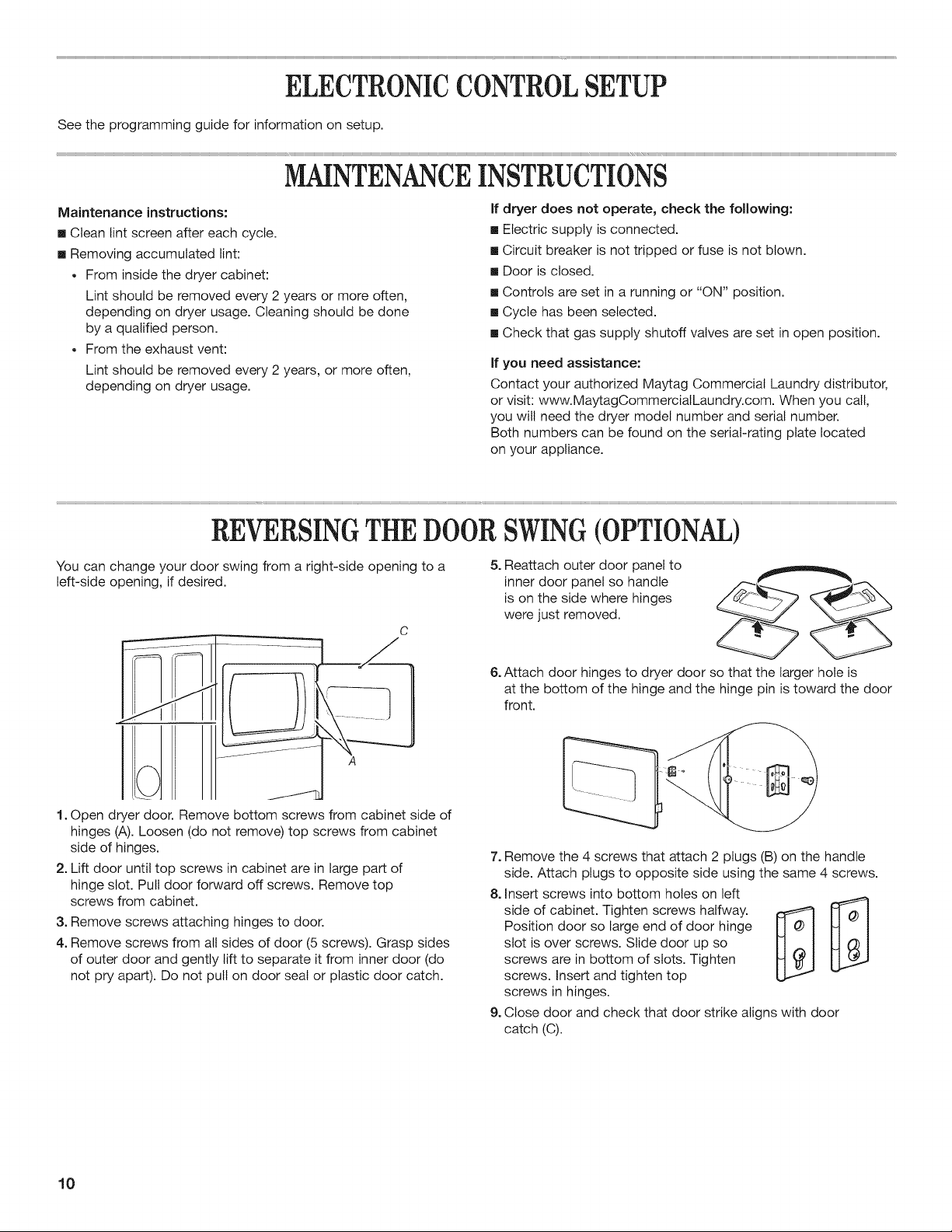
REVERSINGTHE DOOR SWING (OPTION )
You can change your door swing from a right-side opening to a
left-side opening, if desired.
C
1. Open dryer door. Remove bottom screws from cabinet side of
hinges (A). Loosen (do not remove) top screws from cabinet
side of hinges.
2. Lift door until top screws in cabinet are in large part of
hinge slot. Pull door forward off screws. Remove top
screws from cabinet.
3. Remove screws attaching hinges to door.
4. Remove screws from all sides of door (5 screws). Grasp sides
of outer door and gently lift to separate it from inner door (do
not pry apart). Do not pull on door seat or plastic door catch.
5. Reattach outer door panel to
inner door panel so handle
is on the side where hinges
were just removed.
6. Attach door hinges to dryer door so that the larger hole is
at the bottom of the hinge and the hinge pin is toward the door
front.
7. Remove the 4 screws that attach 2 plugs (B) on the handle
side. Attach plugs to opposite side using the same 4 screws.
8. Insert screws into bottom holes on left
side of cabinet. Tighten screws halfway. _ _1
Position door so large end of door hinge
slot is over screws. Slide door up so
screws are in bottom of slots. Tighten
screws. Insert and tighten top
screws in hinges.
9. Close door and check that door strike aligns with door
catch (C).
10

TECHNICALSPECIFICATIONS.GASDRYER
220-240V-50Hz lph 12A max. IP24 Clothes capacity: 9.0 kg max.
European Country:
European Gas Category:
Gas Flow Rate:
Supply Pressure (G20):
Factory Adjusted Pressure:
European Country:
European Gas Category:
Butane Supply Pressure (G30):
Adjusted Pressure:
Propane Supply Pressure (G31):
Adjusted Pressure:
CH, CZ, CY, ES, GB, GR, HR,
IE, IT, PT, Sl, SK, TR
112H3+
0.562703 m3/hr
20 mbar
7.4 mbar
AT, CH, CY, CZ, DK, EE, FI, GR,
HU, IT, NO, RO, SE, SK, TR
112H3B/P
0.562703 m3/hr
20 mbar
7.4 mbar
CH, CZ, CY, ES, GB, GR, HR,
IE, IT, PT, Sl, SK, TR
112H3+
28-30 mbar
N/A
37 mbar
N/A
AT, CH, CY, CZ, DK, EE, FI, GR,
HU, IT, NO, RO, SE, SK, TR
112H3B/P
30 mbar
N/A
30 mbar
N/A
European Country: FR, BE
European Gas Category: 12E+
Supply Pressure (G20): 20 mbar
Supply Pressure (G25): 25 mbar
Adjusted Pressure: N/A
NOTE: Conversion kit : From Natural Gas to LP Gas :Whirlpool Part No. W10233219.
Conversion kit : From Natural Gas to Natural Gas - France/Belgium: Whirlpool Part No. W10184947.
Manufacturer : Whirlpool Corporation, Benton Harbor, Michigan 49022, USA.
11

MAYTAG COMMERCIAL WASHEP DRYER, STACKED DRYER/
DRYER, COMMERCIAL STACK LAUNDRY, AND MULTi-LOAD
COiN OPERATED COMMERCIAL WASHERS AND DRYERS
WAR NTY
LiMiTED WARRANTY ON PARTS
For the first five years from the date of purchase, when this commercial appliance is installed, maintained and operated according to the
instructions attached to or furnished with the product, Maytag brand of Whirlpool Corporation (thereafter "Maytag") will pay for factory
specified parts or original equipment manufacturer parts to correct defects in materials or workmanship. Proof of original purchase date
is required to obtain service under this warranty.
iTEMS MAYTAG WiLL NOT PAY FOR
1. All other costs including labor, transportation, or custom duties.
2. Service calls to correct the installation of your commercial appliance, to instruct you how to use your commercial appliance, to
replace or repair fuses, or to correct external wiring or plumbing.
3. Repairs when your commercial appliance is used for other than normal, commercial use.
4. Damage resulting from improper handling of product during delivery, theft, accident, alteration, misuse, abuse, fire, flood, acts of
God, improper installation, installation not in accordance with local electrical or plumbing codes, or use of products not approved
by Maytag.
5. Pickup and Delivery. This commercial appliance is designed to be repaired on location.
6. Repairs to parts or systems resulting from unauthorized modifications made to the commercial appliance.
7. The removal and reinstallation of your commercial appliance if it is installed in an inaccessible location or is not installed in
accordance with published installation instructions.
8. Chemical damage is excluded from all warranty coverage.
9. Changes to the building, room, or location needed in order to make the commercial appliance operate correctly.
DiSCLAiMER OF iMPLiED WARRANTIES; LiMiTATiONS OF REMEDIES
CUSTOMER'S SOLE AND EXCLUSIVE REMEDY UNDER THIS LIMITED WARRANTY SHALL BE PRODUCT REPAIR AS PROVIDED
HEREIN. iMPLiED WARRANTIES, INCLUDING WARRANTIES OF MERCHANTABiLiTY OR FITNESS FOR A PARTICULAR PURPOSE,
ARE LIMITED TO ONE YEAR OR THE SHORTEST PERIOD ALLOWED BY LAW. WHIRLPOOL SHALL NOT BE LIABLE FOR
INCIDENTAL OR CONSEQUENTIAL DAMAGES. SOME STATESAND PROVINCES DO NOT ALLOW THE EXCLUSION OR LiMiTATION
OF INCIDENTAL OR CONSEQUENTIAL DAMAGES, OR LIMITATIONS ON THE DURATION OF IMPLIED WARRANTIES OF
MERCHANTABILITY OR FITNESS, SO THESE EXCLUSIONS OR LIMITATIONS MAY NOT APPLY TO YOU. THIS WARRANTY GIVES
YOU SPECIFIC LEGAL RIGHTS AND YOU MAY ALSO HAVE OTHER RIGHTS, WHICH VARY FROM STATE TO STATE OR PROVINCE
TO PROVINCE.
If you need service, please contact your authorized Maytag Commercial Laundry distributor. To locate your authorized Maytag
Commercial Laundry distributor, or for web inquiries, visit www.MaytagCommercialLaundry.com.
9/07
For written correspondence:
Maytag Commercial Laundry Service Department
2000 M-63 North
Benton Harbor, Michigan 49085 USA
12
SECURITEDUSECHE.LINGE
Votre securite et celle des autres est tres importante.
Nous donnons de nombreux messages de s_curite importants dans ce manuel et sur votre appareil m_nager. Assurez-vous de
toujours lire tous les messages de s_curite et de vous y conformer.
Voici le symbole d'alerte de s_curit&
Ce symbole d'alerte de s_curit_ vous signale les dangers potentiels de d_c_s et de blessures graves h vous
et h d'autres.
Tousles messages de securite suivront le symbole d'alerte de s_curite et le mot "DANGER" ou
"AVERTISSEMENT". Ces mots signifient •
Risque possible de d6cbs ou de blessure grave si vous ne
suivez pas imm6diatement les instructions.
Risque possible de d6cbs ou de blessure grave si vous
ne suivez pas les instructions.
Tousles messages de s_curite vous diront quel est le danger potentiel et vous disent comment r_duire le risque de blessure et
ce qui peut se produire en cas de non-respect des instructions.
POUR VOTRE SECUR{TE
1. Ne pas utiliser ou remiser d'essence ou autres materiaux inflammables darts cet appareit menager ou h proximite de cetu{-ci.
2. Ne pas vaporiser d'aerosols _.proximite de cet appareil menager Iorsqu'il est en fonctionnement.
3. Ne pas modifier cet appareit menager.
AVERTISSENiENT • Pour votre securite, les renseignements darts ce manuel doivent
0tre observes pour reduire au minimum les risques d'incendie ou d'explosion ou pour
eviter des dommages au produit, des blessures ou un deces.
- Ne pas entreposer ou utiliser de I'essence ou d'autres vapeurs ou liquides
inflammables h proximite de cet appareil ou de tout autre appareil electromenager.
-QUE FAIRE DANS LE CAS D'UNE ODEUR DE GAZ :
®Ne pas tenter d'allumer un appareil.
• Ne pas toucher a un commutateur electrique; ne pas utiliser le telephone se trouvant
sur les lieux.
Evacuer tous les gens de la piece, de I'edifice ou du quartier.
Appeler immediatement le fournisseur de gaz d'un telephone voisin. Suivre ses
instructions.
h. d(ifaut de joindre votre fournisseur de gaz, appeler les pompiers.
- L'installation et I'entretien doivent 0tre effectues par un installateur qualifie, une
agence de service ou le fournisseur de gaz.
13
#
ELIMINATIONDUSECHE-LINGE
Le marquage de I'appareil est conforme b,la directive europ6enne 2002/96/EC sur les 6quipements 61ectroniques et
electriques, pour gestion des dechets.
En veillant h I'_limination correcte de ce produit, vous 6viterez d'_ventuelles cons6quences n_fastes pour I'environnement et la
sant_ humaine qui peuvent _tre assocl6es au traitement inappropri_ de ce prodult Iorsqu'il a _t_ mis au rebut.
Le symbole figurant sur le produit ou dans les documents qui accompagnent {e produit indique que cet appareil ne dolt pas _tre
trait_ comme dechet menager; on dolt plut6t le remettre hun centre de collecte specialise pour le recyclage des _quipements
electriques et electroniques.
L'elimination de ce produit apres mise au rebut dolt _tre effectu_e conformement aux prescriptions de la reglementation locale
de protection de I'environnement.
Pour I'information d_taill6e concernant le traitement, le recyclage et la r_cup_ration de ce produit, contacter la municipalit_
locale, le service d'_limination des d_chets m_nagers, ou le commer(2ant qui a vendu le produit.
EXIGENCESD'INSTALLATION
X
Rassembler les outils et pi_ces necessaires avant de commencer
I'instattation. Life et respecter les instructions d'instattation
fournies avec chacun des outits de cette liste.
Outil{age n6cessaire
[] Cte h tube de 20 cm (8") [] Couteau utititaire
ou 25 cm (10") [] Brides de fixation
[] Cte h molette de 20 cm (8") [] Compose d'etancheite des
ou 25 cm (10") raccords fitetes - r_sistant
[] Tournevis h lame plate au propane
[] Tournevis Phillips [] Pistotet h calfeutrage et
[] Cle & molette avec compose de catfeutrage
ouverture jusqu'h 25 mm (pour I'instatlation d'un
(1") ou cte & douille h t_te nouveau circuit
hexagonale d'evacuation)
[] Niveau [] Pince
[] Cle h douille de 8 mm [] Couteau h mastic
(5/16")
Pi_ces fournies
Retirer le sac de pi_ces du tambour du s_che-linge. V_rifier la
presence de toutes les pi_ces.
[] Patin (4)
[] Pied du s_che-linge (4)
REMARQUE : Le schema de circuits de ce seche-tinge se trouve
I'interieur du panneau inferieur avant.
14
 Loading...