

Marantz RX-7001 Owners Manual

Model RX7001 User Guide
RF Extender


RX7001
User Guide
Guía del usuario
ENESFR
Mode d’emploi
Benutzeranleitung
DE


RF Extender
User Guide
EN
User Guide
1
RF Extender User Guide
© Copyright 2005 Marantz Europe B.V. P.O. Box 8744, 5605 LS Eindhoven, The
Netherlands
Remark:
All rights are reserved. Reproduction in whole or in part is prohibited without prior
consent of the copyright owner.
Marantz Europe B.V. is not liable for omissions or for technical or editorial errors in
this manual or for damages directly or indirectly resulting from the use of the
RX7001 Extender.
The information in this user guide may be subject to change without prior notice.
All brand or product names are trademarks or registered trademarks of their
respective companies or organizations.

Contents
Contents 2
How to Use the RF Extender 3
How to Install the RF Extender 5
How to Do More 12
Introduction 3
How to Connect the RF Extender 5
How to Position the Blaster Unit 6
How to Install the Dual IR Emitters 7
How to Position the Receiver Unit 9
How to Set the Extender IDs 12
How to Avoid Interference from Other Marantz remote controls 13
How to Use a Longer Connection Cable 13
How to Fine-Tune the Installation Using the Dip Switches 14
How to Turn Off the IR Blaster 14
How to Set the Dual IR Emitter Power Levels 14
Troubleshooting 16
Specifications 17
User Guide
2
How to Use the RF Extender
Introduction
Infrared (IR) remote controls do not work properly when obstacles between the
remote control and the audio/video devices disturb the operating signal. This
problem can be solved using radio frequency (RF) as a carrier for IR commands.
The Marantz touch screen remote controls (see note below), in combination with
the RF Extender, can operate audio/video devices from virtually any location.
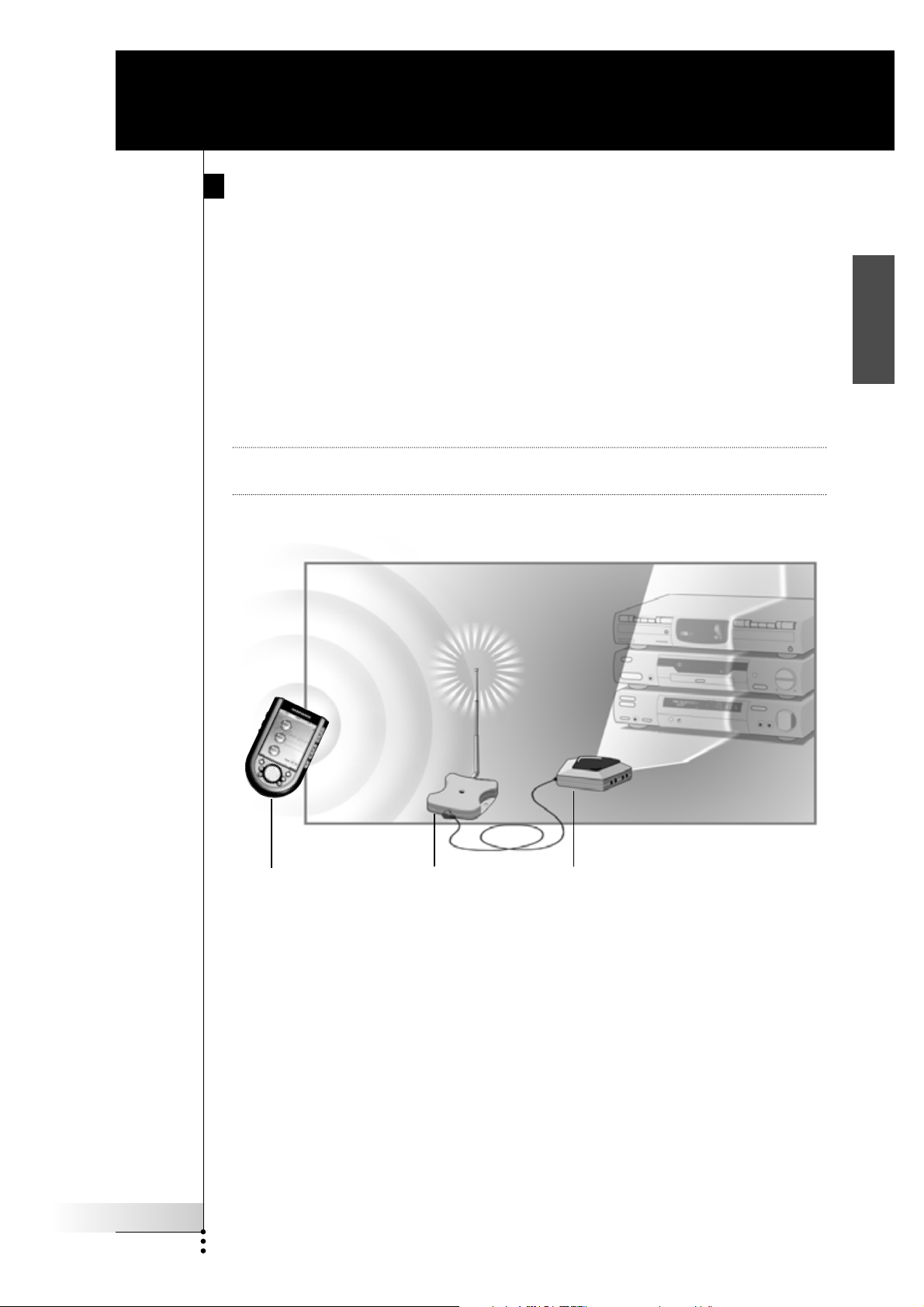
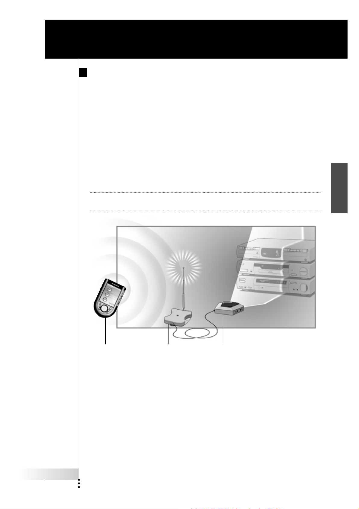
The RF Extender consists of two units: a Receiver unit, and a Blaster unit.
The Receiver unit receives RF signals sent out by the Marantz touch screen remote
controls. This unit is connected to the Blaster unit, which converts the signals into
IR signals. The Blaster unit then transmits the IR signals to the audio/video devices.
Note Only applicable for the Marantz RC5200, RC5400 RC9200 and the RC9500 touch
screen remote controls.
EN
RF signals
Marantz Receiver unit Blaster unit
IR signals
When the Blaster unit cannot reach all devices or transmits with too much power,
you can use the included Dual IR emitters. You can set up the Dual IR emitters in
two ways:
■ The Dual IR emitters in combination with the Blaster unit.
When there is limited space around the IR receivers of the devices, for
instance in a small closet.
■ The Dual IR emitters instead of the Blaster unit.
When you want to transmit IR signals very accurately, you turn off the Blaster
unit, and control the devices by using the Dual IR emitters alone.
User Guide
3
How to Use the RF Extender
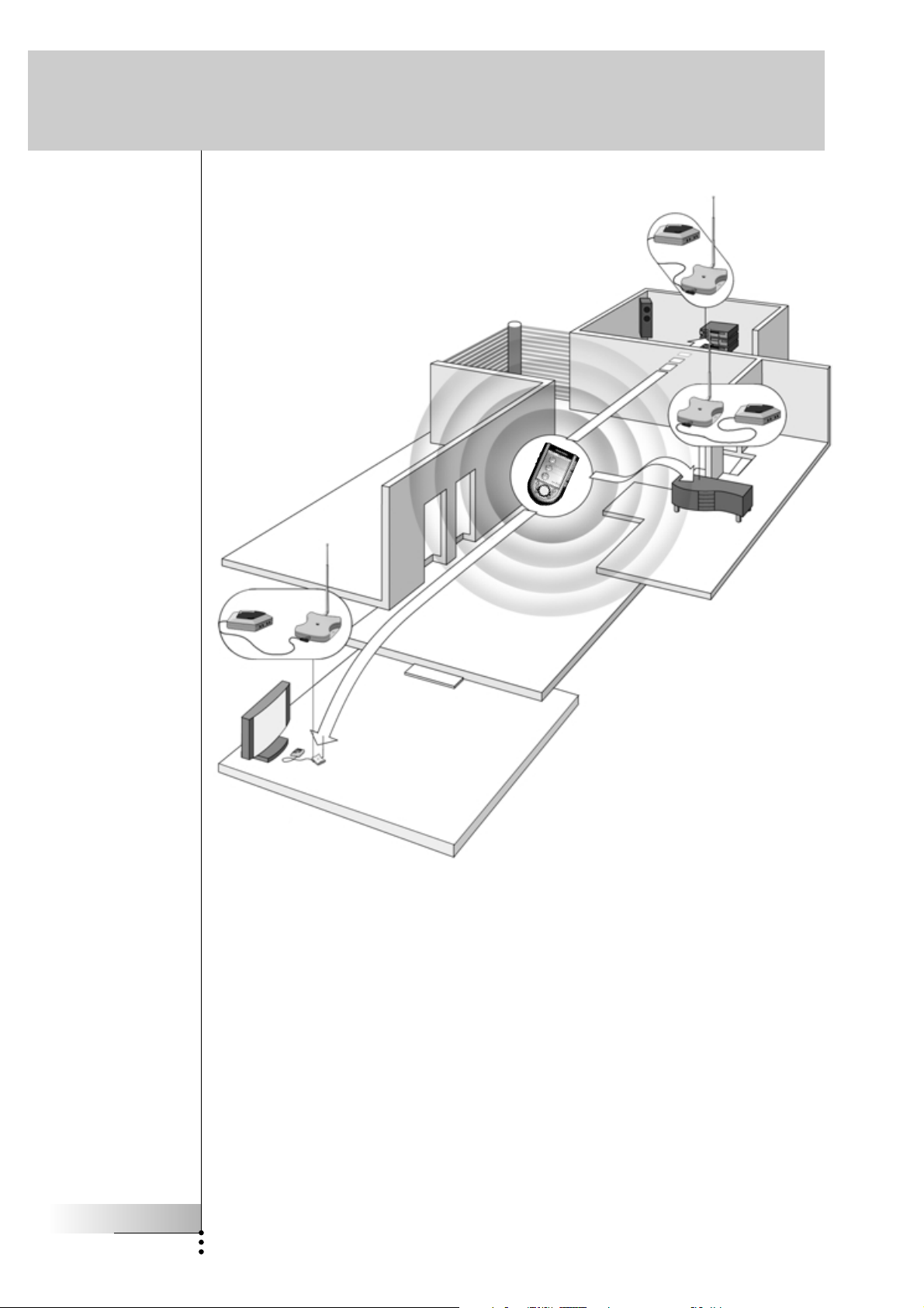
Situation B:
The RF Extender
controls devices placed
in an adjacent room.
Situation A:
Your devices can be
remotely controlled
when they are not in
the line of sight of the
remote control.
Situation C:
The RF Extender is
placed inside a closet,
a rack or another piece
of furniture together
with your devices.
The arrangements in the situation shown above can also be combined. You can
control all RF Extenders individually with one or more Marantz touch screen
remote controls.
User Guide
4
How to Install the RF Extender
Make sure you have the following components: RF Extender Receiver unit,
RF Extender Blaster unit, power adapter, connection cable, Dual IR emitters and
screws.
The installation of the RF Extender consists of 4 main steps:
■ Connecting the RF Extender;
■ Positioning the Blaster unit;
■ Installing the Dual IR emitters;
■ Positioning the Receiver unit.
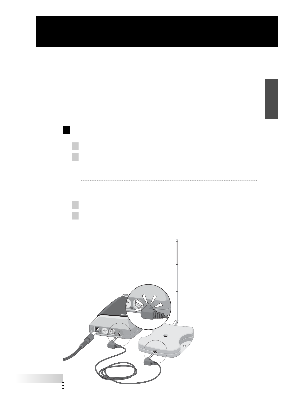
How to Connect the RF Extender
1 Plug the power cable into the Blaster unit.
2 Plug the power adapter into the mains wall socket.
When connected, a red LED on the Blaster unit will start blinking.
After a few seconds, the LED will stop blinking and stay on.
EN
Remark The LED on the Blaster unit will also blink when the Blaster unit sends out
IR signals to the audio/video devices.
3 Plug the connection cable into the Blaster unit until it clicks.
4 Plug the connection cable into the Receiver unit until it clicks.
When connected, the LED on the Receiver unit will stay on for 3 seconds.
Afterwards, the LED will go off.
User Guide
5
How to Install the RF Extender
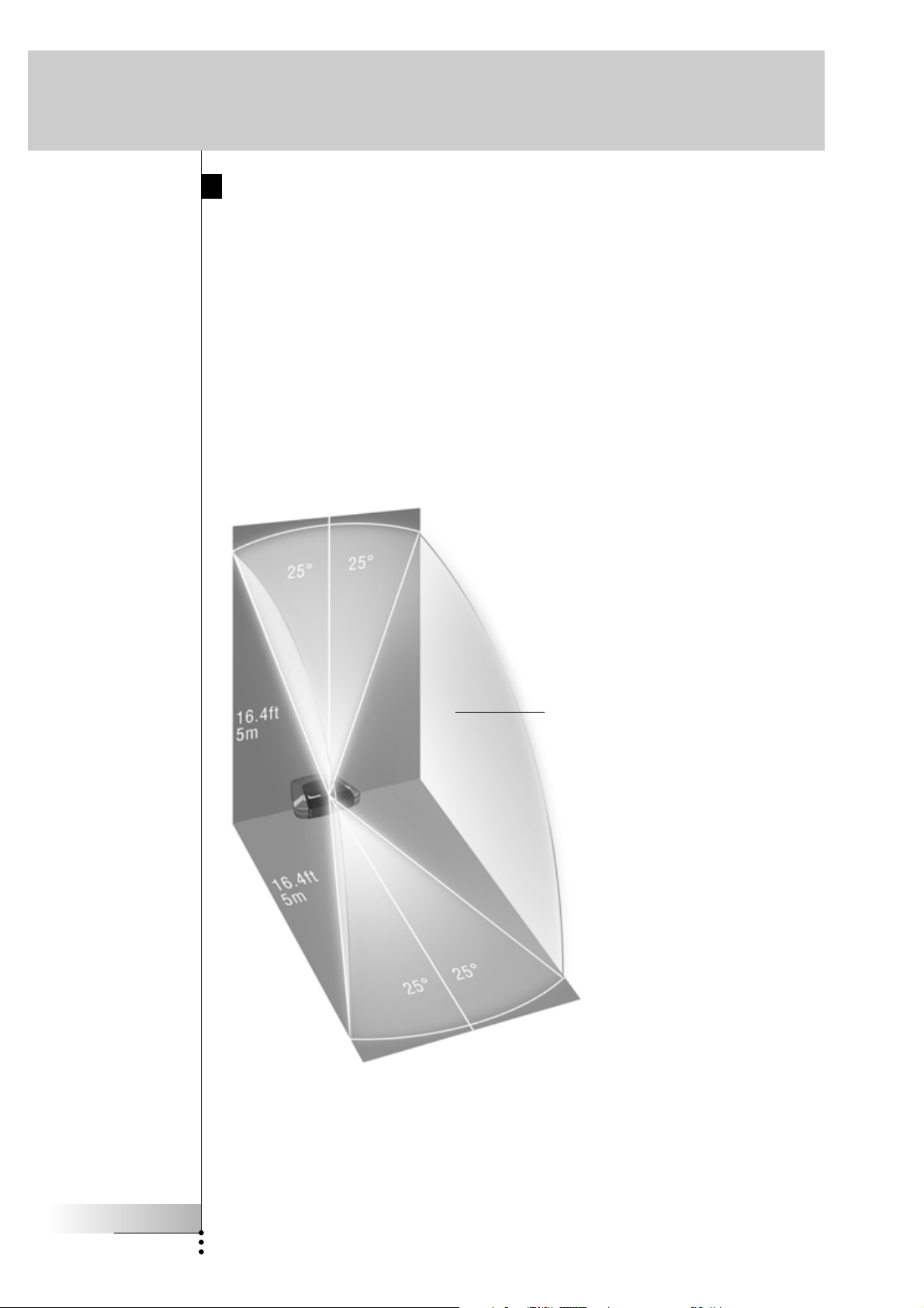
How to Position the Blaster Unit
For optimal results, the Blaster unit should be positioned horizontally, either facing
up, or facing down.
Make sure to place the Blaster unit in a central position aimed directly at the
audio/video devices. The IR blaster (the dark plastic window on top of the Blaster
unit) in particular should be aimed at the devices, since the IR signals sent out by
the IR blaster must reach the IR receivers of the devices.
For optimal IR reception, position the Blaster unit so the devices are located within
the working range of the Blaster unit, as shown in the picture below.
IR reflection area
User Guide
6
How to Install the RF Extender
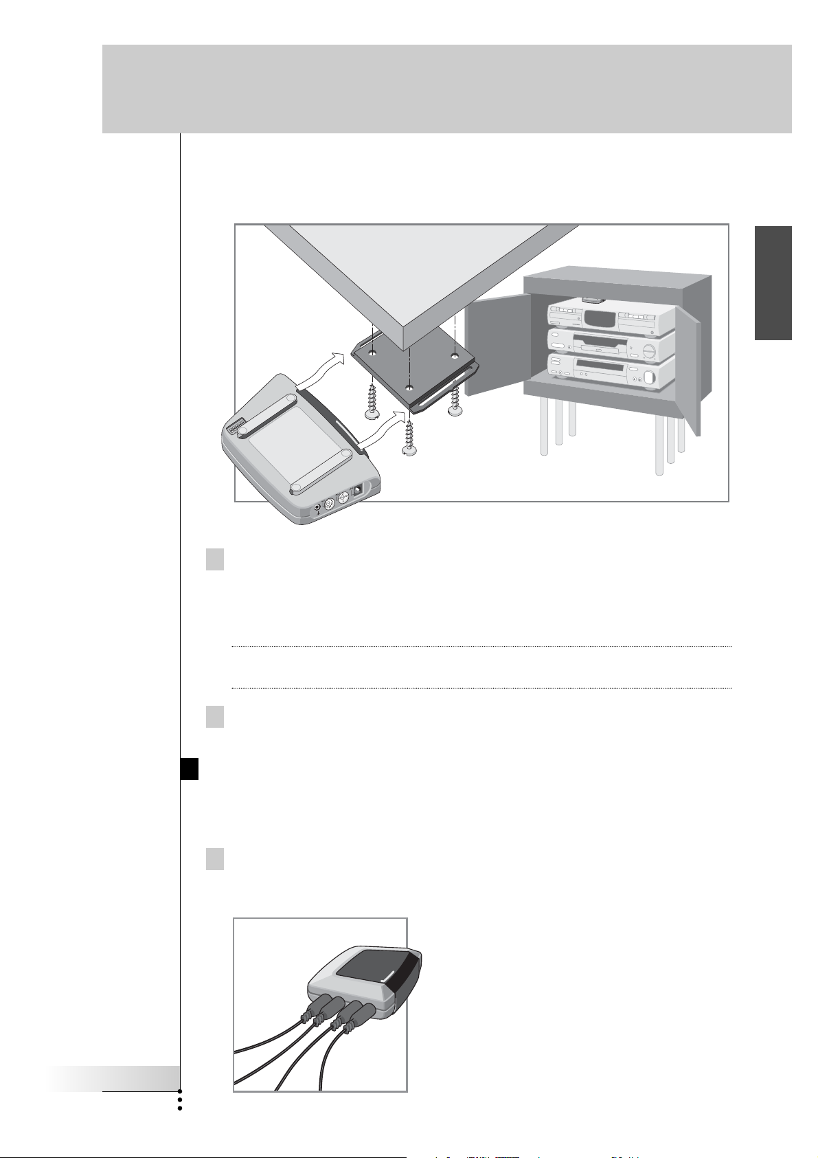
Once you have found the best position, you can optionally mount the Blaster unit
onto a piece of furniture using the mounting plate and screws, which are included.
EN
1 Screw the mounting plate to a rack, closet or another piece of
furniture.
Provide sufficient space to connect the power adapter and to slide the Blaster
unit back on.
Tip Depending on the surface, it may be possible to attach the mounting plate to
the furniture using a piece of 2-sided tape or velcro.
2 Slide the Blaster unit onto the mounting plate.
How to Install the Dual IR Emitters
The Dual IR emitters can be used in combination with, or as an alternative for the
Blaster unit.
1 Plug the Dual IR emitters into the Blaster unit.
User Guide
7
How to Install the RF Extender
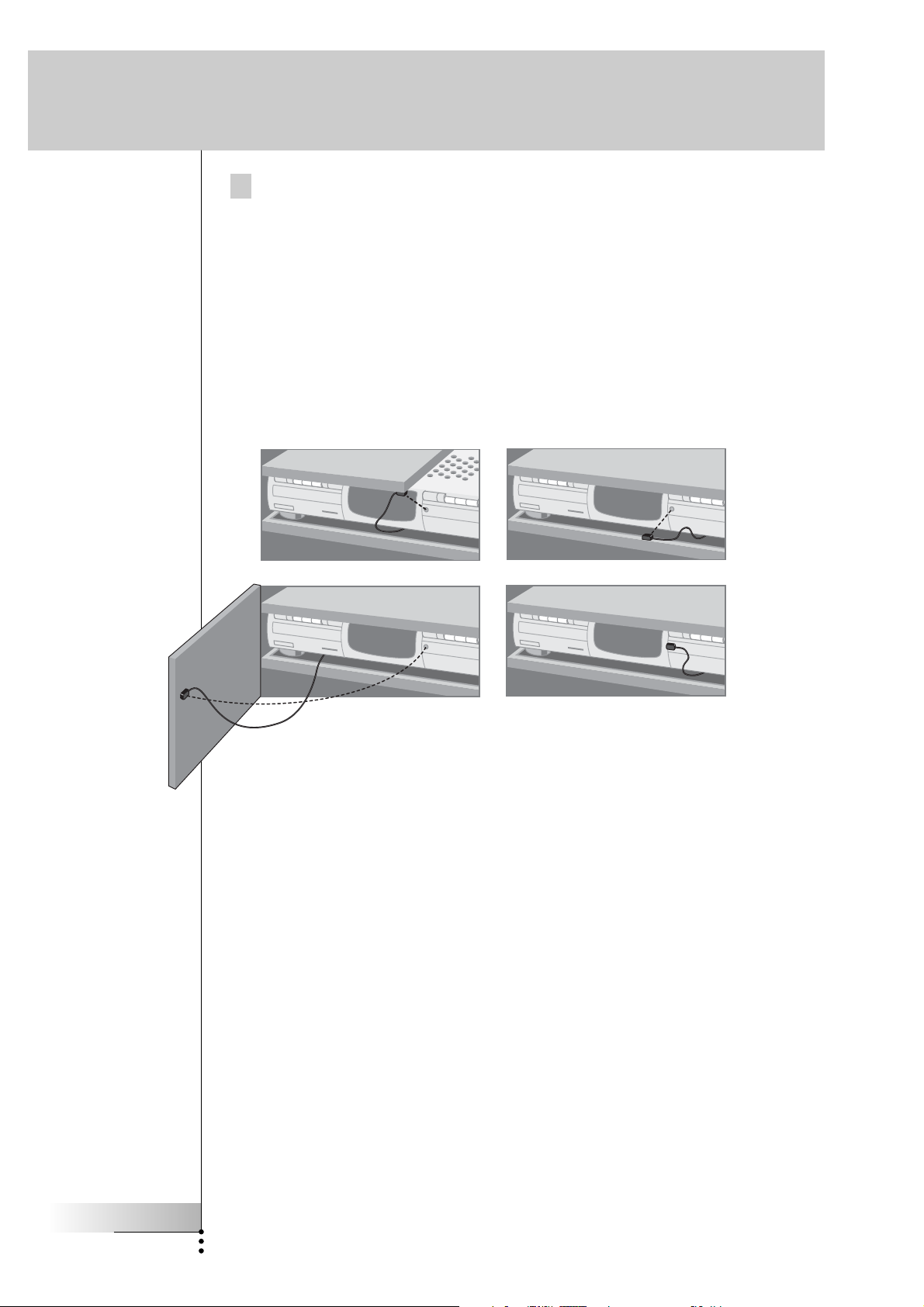
2 Attach the Dual IR emitters to a neighboring surface facing the
IR receiver (for aesthetic purposes or when it is difficult to locate the
IR receiver).
– OR –
Attach the Dual IR emitters directly to the IR receivers of the
audio/video devices.
Make sure the Dual IR emitters are connected properly and that they are placed
within range of the IR receivers.
User Guide
8
How to Install the RF Extender
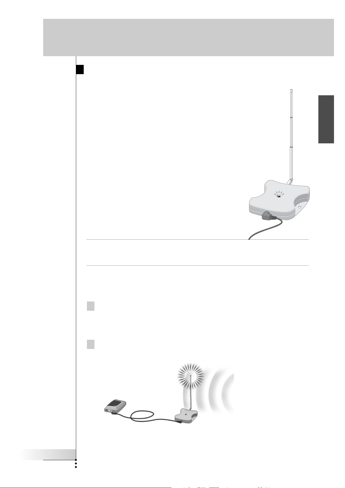
How to Position the Receiver Unit
For optimal performance, the Receiver unit should be placed
in a location where there is little or no RF interference.
In most cases, however, you will notice no RF interference.
There may be RF interference when other appliances
(such as WiFi base stations, audio/video devices, microwave
ovens, or wireless telephones) are operated nearby.
The LED on the Receiver unit indicates the
amount of RF interference.
The amount of RF interference present is indicated by the
rate at which the LED blinks and the brightness of the LED
when blinking (a higher rate of blinking and a brighter
light means more RF interference).
To avoid interference, place the Receiver unit in a
position in which the Receiver unit LED blinks and burns
as little as possible.
EN
Remark Do not operate the Marantz touch screen remote control while positioning the
Receiver unit, since both RF interference and operation of the Marantz touch
screen remote control will cause the LED of the Receiver unit to blink.
To find the position with the least amount of RF interference, try out the
following steps:
1 Try to create the worst-case scenario, by turning on all devices that
may cause RF interference. If the RF Extender and the Marantz touch
screen remote control works properly in this scenario, they will
certainly work in other situations.
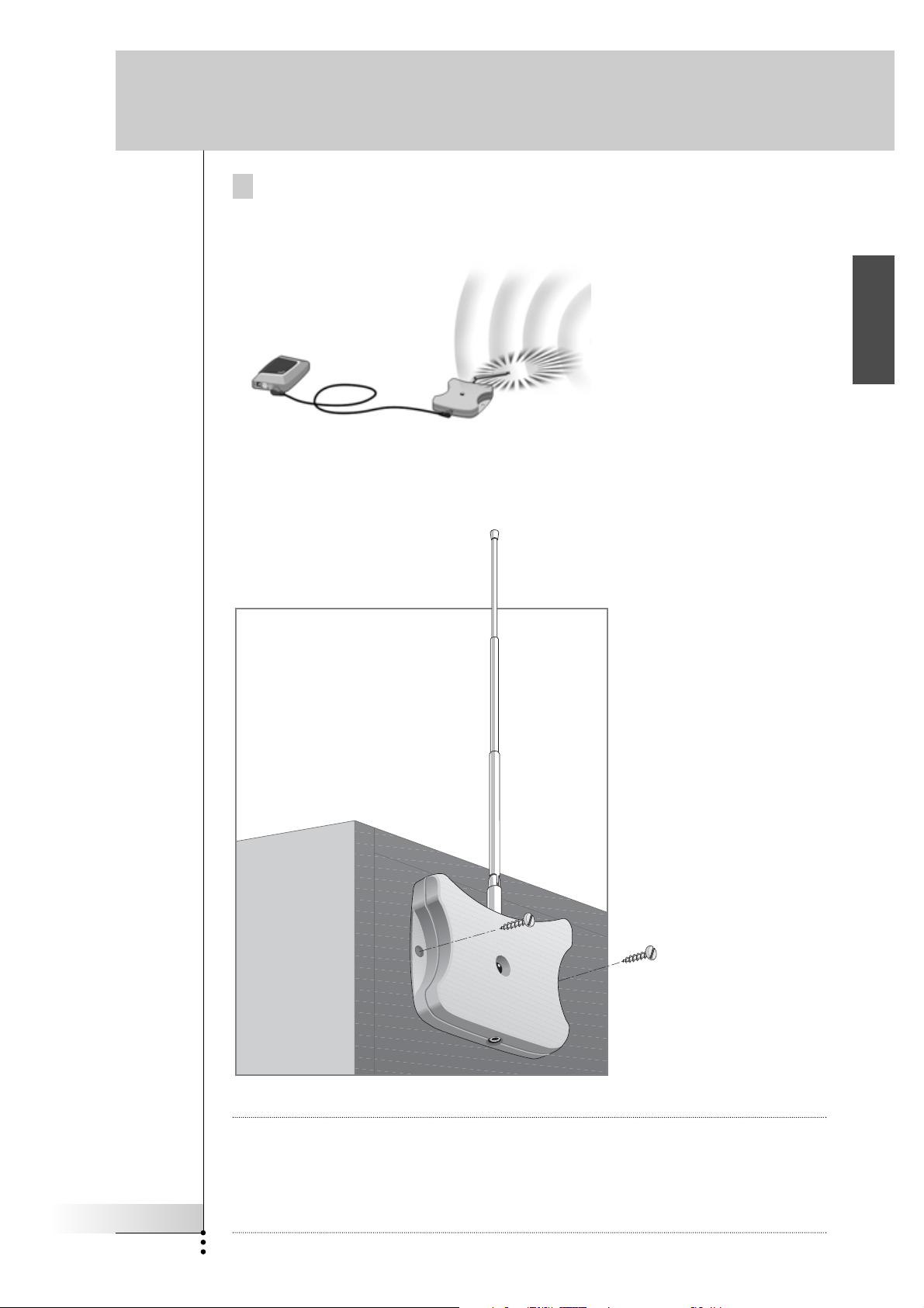
2 Extend the antenna of the Receiver unit, and direct it upwards.
User Guide
9
How to Install the RF Extender
3 Check the LED on the Receiver unit for RF interference.
If the LED does not blink, or blinks only sporadically, position the Receiver unit
there, and continue with step 7. If the LED still blinks, continue with the next
step.
Note When the LED blinks only sporadically, with low light intensity, there are no
problems with RF interference.
4 Try out other positions moving the Receiver unit around, and check the
LED for RF interference.
If the LED does not blink, or blinks only sporadically, mount the Receiver unit in
that place, and continue with step 7. If the LED still blinks, continue with the
next step.
Tip Do not position the Receiver unit:
■ Near audio/video devices, since these devices may cause RF interference.
In particular, keep the Receiver unit away from optical audio/video devices,
such as a DVD player.
■ Near microwave ovens or wireless access points.
■ Inside a metal closet, since metal objects can disturb RF signals.
5 Retract the antenna, keeping it directed upwards.
Retracting in the antenna will cause the Receiver unit to be less sensitive to
interference. It will also decrease the working range of the Marantz touch
screen remote control.
6 Try out other positions moving the Receiver unit around, and check the
LED for RF interference.
If the LED does not blink, or blinks only sporadically, mount the Receiver unit in
that place.
7 Try out your Marantz touch screen remote control.
When sending commands with the Marantz touch screen remote control, the
LEDs of both the Receiver unit and the Blaster unit should blink.
User Guide
10
How to Install the RF Extender
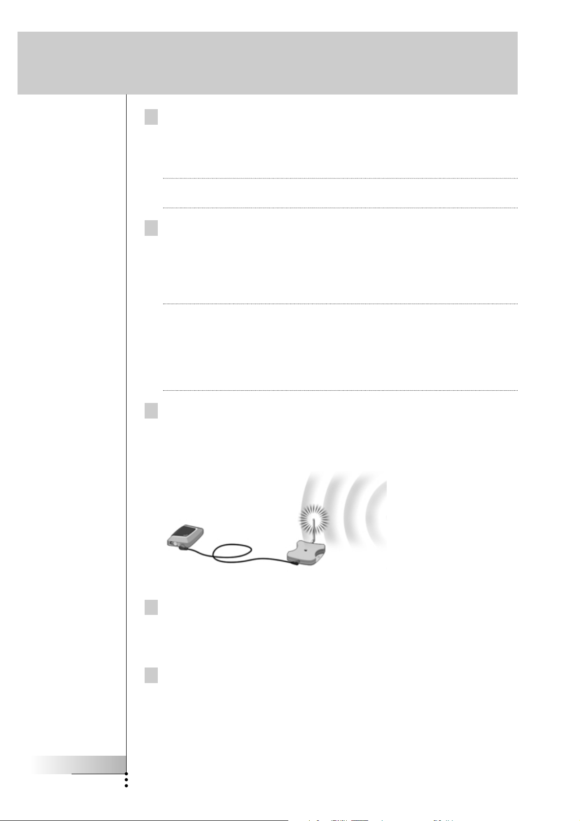
8 If necessary, aim the antenna in the direction where the Marantz touch
screen remote control will be used, to improve the performance in that
direction.
Once you have found the best position you can optionally mount the Receiver
unit onto a piece of furniture using 2 screws.
EN
User Guide
11
Tip Depending on the surface, it may be possible to attach the Receiver unit to the
furniture using a piece of 2-sided tape or velcro. Find the right position and make
sure there is sufficient space.
When the cable for connecting the Receiver unit and the Blaster unit is too short,
you can use a longer cable (see How to Use a Longer Connection Cable p. 13).
How to Do More
How to Set the Extender IDs
The RF Extender can be used in several situations as illustrated in the picture on
p. 4: out of sight, in an adjacent room, or inside a closet.
Since the RF Extender ‘communicates’ with the Marantz touch screen remote
control, you must set the same Extender ID (identity) on both appliances. The
settings depend on whether you have a single RF Extender or multiple RF Extenders.
Single RF Extender
When you use only one RF Extender, you can accept the default setting for the
Extender ID (ID=0).
■ On the Marantz touch screen remote control, choose the same Extender ID for
each device controlled by the RF Extender.
Refer to the User Guide of Marantz remote control for more information.
Multiple RF Extenders
If you want to operate several of your devices independently, e.g. grouped in
different locations, you need multiple RF Extenders. When using several
RF Extenders, it is important to assign a unique Extender ID to each Blaster unit.
You can assign 16 Extender IDs (from 0 to 9 and from A to F).
For the three RF Extenders in the picture on p. 4, you can set the Extender IDs as
described below:
■ For situation A, set the Extender ID to 0;
■ For situation B, set the Extender ID to 1;
■ For situation C, set the Extender ID to 2.
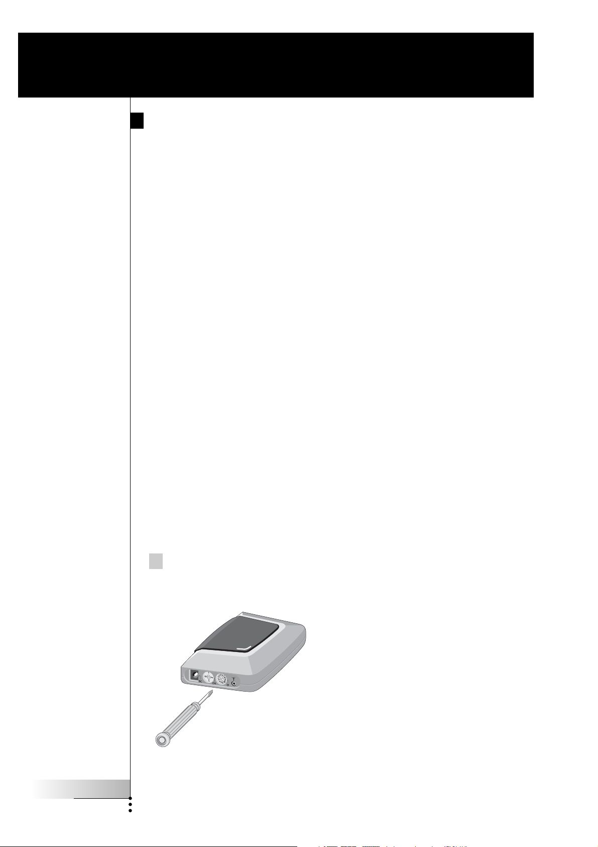
1 Choose an Extender ID for the Blaster unit by turning the ID dial with a
small screwdriver.
User Guide
12

How to Do More
2 On the Marantz touch screen remote control, choose the same
Extender ID for each device controlled by the RF Extender.
Refer to the User Guide of Marantz remote control for more information.
3
Try to operate the devices with the Marantz touch screen remote control.
The red LED on the Blaster unit will blink when the RF Extender receives a
correct command.
Note The LED of the Receiver unit will always blink when RF signals are being
received, even when the extender ID of the Marantz touch screen remote
control and the Extender ID of the blaster do not match.
The LED of the Blaster unit will blink only when the configuration of the
Marantz touch screen remote control matches the Extender ID on the Blaster unit.
4 Repeat this procedure for every RF Extender.
How to Avoid Interference from Other Marantz remote
controls
EN
If the red LED on the Blaster unit is blinking without the Marantz touch screen
remote control sending commands, the Receiver unit picks up signals from another
Marantz touch screen remote control on the same channel. You can solve this
problem by changing the channel.
You configure the channel on the Marantz touch screen remote control and on the
Blaster unit. Both channels must be the same. Four channels (CH from 0 to 3) can be
assigned.
1 Choose a channel on the Blaster unit by turning the CH dial with a
small screwdriver.
2 On the Marantz touch screen remote control, choose the same
channel.
Refer to the User Guide of Marantz remote control for more information.
3 Try to operate your devices with the Remote Control.
How to Use a Longer Connection Cable
When the connection cable included is not long enough to connect the Receiver
unit to the Blaster unit, you can use a longer cable (up to 20 ft / 6 m). You can
connect the Receiver unit to the Blaster unit with a standard shielded stereo audio
cable with 2.5 mm male jacks on both sides.
User Guide
13

How to Do More
How to Fine-Tune the Installation Using the Dip Switches
At the bottom of the Blaster unit, you find 5 dip switches (numbered 1-5). When
you use Dual IR emitters to send the IR signals to the audio/video devices,
configure the dip switches to:
■ Turn the IR blaster on or off (independently from the Dual IR emitters);
■ Configure the power levels of the Dual IR emitters, e.g.:
■ When you configure the Dual IR emitters in wired IR solutions using a
connecting block.
In this case, you can adjust the power levels of the Dual IR emitters.
■ When you use a device that interferes with IR signals, such as a plasma
TV set.
In this case, you can raise the power levels of the Dual IR emitters, since
plasma technology might cause IR interference.
■ When you want to operate 2 identical devices that are placed next to each
other using 2 RF Extenders.
In this case, you can lower the power levels of the Dual IR emitters, in
order to prevent the devices from receiving IR signals intended for another
device.
Switch Switches 1 + 2 Switches 3 + 4 Switch 5
Function Dual IR emitters 1 - 2 Dual IR emitters 3 - 4 IR blaster
Power level Power level On/Off
By default, all dip switches are set to 1 (On).
How to Turn Off the IR Blaster
When you decide to control the audio/video devices with Dual IR emitters only,
you can turn off the IR blaster of the Blaster unit.
■ To turn off the IR blaster, set switch 5 to 0 (Off).
How to Set the Dual IR Emitter Power Levels
You can use dip switches 1 to 4 to set the power level of the Dual IR emitters.
To set the power level:
■ For Dual IR emitters 1 and 2, use switches 1 and 2;
■ For Dual IR emitters 3 and 4, use switches 3 and 4.
You can choose between 4 power levels (0, 1, 2 and 3). By default, power
level 3 is selected for each group of Dual IR emitters.
User Guide
14

How to Do More
You can set the power level as indicated below:
Power level Switch 1 Switch 2 Switch 3 Switch 4
(Operating distance)
0 (0.7 m) 0 (Off) 0 (Off) 0 (Off) 0 (Off)
1 (1.5 m) 0 (Off) 1 (On) 0 (Off) 1 (On)
2 (2.0 m) 1 (On) 0 (Off) 1 (On) 0 (Off)
3 (2.5 m - default setting) 1 (On) 1 (On) 1 (On) 1 (On)
Remark The Dual IR emitters still send out IR signals when the power level is set to zero.
The emission is never completely turned off.
EN
User Guide
15

Troubleshooting
The red LED on the Receiver unit blinks when the Marantz touch
screen remote control is not being used
■ This indicates RF interference. See p. 9.
The red LED on the Blaster unit blinks when the Marantz touch
screen remote control is not being used
■ This indicates that another Marantz touch screen remote control is being used
in the proximity of the Receiver unit. See p. 13.
There is no red LED on my Blaster unit
■ Make sure the power adapter is connected properly. See p. 5.
The red LED on the Receiver unit does not blink when connecting
it to the Blaster unit
■ Make sure the power adapter is connected properly to the Blaster unit.
See p. 5.
■ Make sure the connection cable between the Receiver unit and the Blaster
unit is connected properly. See p. 5.
The Dual IR emitters are no longer adhesive
■ Replace the adhesive with a fresh piece of transparent 2-sided tape.
I cannot find the exact location of the device’s IR receiver
■ Set the Dual IR emitters to the minimal power level, and hold one of the
emitters 0.4 - 0.8 inch / 1 - 2 cm in front of the device.
Move the emitter across the front panel, and take note of when the device
reacts to the IR signals of the emitter.
When the device reacts, position the emitter in that place.
■ Check the manual for the device.
If you are still in doubt, contact your supplier or the manufacturer.
User Guide
16

Specifications
The specifications and design of this product are subject to change without notice.
Hardware Blaster unit Red LED (continuously on when powered, blinking
during IR emission)
16 IDs and 4 CHs
4 outputs for IR emitters
Input for Receiver unit
Possibility of having multiple RF extenders in one
home not interfering
Positioning: freestanding, mounted horizontally or
hanging up side down
Hardware Receiver unit Red LED (blinking when receiving RF commands and
RF interference)
Output for Blaster unit
RF antenna
Dimensions Blaster unit 4.5 x 3.2 x 1.1 inch (112.9 x 81.2 x 26.8 mm)
EN
Dimensions Receiver unit 3.0 x 2.9 x 0.9 inch (77 x 73 x 23.5 mm)
Dimensions antenna Extended: 0.7 inch (17.7 mm)
Retracted: 0.4 inch (9.7 mm)
Fully rotatable (360°)
Operating temperature 32°F to 122°F (0°C to 50°C)
Infrared (IR) Operating distance: 16.4 ft – 22.9 ft (5-7 meters)
IR frequency range: DC/flash codes, 25kHz-100kHz
Radio Frequency (RF) Operating distance: 147.6 ft (45 m) outdoor
Dual IR emitters Number of IR emitters : up to 8 (4x2), emitters wired in
series
3.5 mm mono mini-plug
Cable length: 10 ft (2.5 meters)
Min. range: 3 ft (75 cm)
Power adapter 230V / 50 Hz AC Power adapter
(400mA/12V DC adapter, CE-approved)
Accessories Connection cable (standard shielded stereo audio
cable, 2.5 mm male jacks on both sides, up to
20 ft / 6 m)
Dual IR emitters
Power adapter
Mounting kit (plate and screws)
User Guide
17


Extensor de RF
Guía del usuario
ES
Guía del usuario
1
Extensor de RF Guía del usuario
© Copyright 2005 Marantz Europe B.V. P.O. Box 8744, 5605 LS Eindhoven, The
Netherlands
Observaciones:
Todos los derechos reservados. Queda prohibida la reproducción total o parcial sin
consentimiento previo del propietario del copyright.
Marantz Europe B.V. no se hace responsable de las omisiones o errores técnicos o
editoriales que pueda contener este manual, ni de los daños directa o
indirectamente resultantes del uso del extensor de RX7001.
La información de este manual del usuario puede estar sujeta a cambios sin previo
aviso. Todos los nombres de marcas y productos son marcas comerciales o marcas
registradas de sus respectivas compañías u organizaciones.

Índice de contenido
Índice de contenido 2
Cómo usar el extensor de RF 3
Introducción 3
Cómo instalar el extensor de RF 5
Cómo conectar el extensor de RF 5
Cómo colocar la unidad Transmisora 6
Cómo instalar los emisores de IR duales 7
Cómo colocar la unidad Receptora 9
Otras operaciones 12
Cómo establecer las identidades del extensor 12
Cómo evitar la interferencia de otros mandos a distancia Marantz 13
Cómo usar un cable de conexión más largo 13
Cómo poner a punto la instalación utilizando los conmutadores DIP 14
Cómo apagar el transmisor de IR 14
Cómo ajustar los niveles de potencia de los emisores de IR duales 15
Resolución de problemas 16
Especificaciones 17
Guía del usuario
2
Cómo usar el extensor de RF
Introducción
Los mandos a distancia por infrarrojos (IR) no funcionan correctamente si existen
obstáculos entre ellos y los dispositivos de audio/vídeo que alteran la señal operativa.
Este problema puede resolverse fácilmente utilizando las radiofrecuencias (RF) para
la transmisión de comandos de IR. Los mandos a distancia Marantz con pantalla táctil
(véase la nota siguiente), en combinación con el Extensor de RF, pueden utilizar
dispositivos de audio/vídeo desde prácticamente cualquier lugar.
El extensor de RF se compone de dos unidades: una unidad Receptora y una
unidad Transmisora. La unidad receptora recibe señales de RF enviadas por los
mandos a distancia Marantz de pantalla táctil. Esta unidad está conectada a la
unidad Transmisora, que convierte las señales en señales de IR. A continuación, la
unidad Transmisora transmite las señales de IR a los dispositivos de audio/vídeo.
Nota Aplicable solamente a los mandos a distancia Marantz de pantalla táctil RC5200,
RC5400, RC9200 y RC9500.
ES
Guía del usuario
Señales de RF Señales de IR
Marantz Unidad
Receptora
Unidad
Transmisora
Cuando la señal de la unidad Transmisora no llega a todos los dispositivos o se
transmite con excesiva potencia, se pueden utilizar los emisores de IR duales
incluidos. Los emisores de IR duales pueden configurarse de dos maneras
distintas:
■ Los emisores de IR duales en combinación con la unidad Transmisora.
Cuando existe poco espacio alrededor de los receptores IR de los dispositivos,
por ejemplo, en el interior de un armario pequeño.
■ Los emisores de IR duales en lugar de la unidad Transmisora.
Cuando se deseen transmitir señales de IR de gran precisión, deberá
desconectarse la unidad Transmisora y controlar los dispositivos utilizando
únicamente los emisores de IR duales.
3
 Loading...