

Page 1
Service
RC9001
RC9001 /
A1S/F S/N1S/T1S/U1S
Manual
Touch Screen Remote Control
RC9001
DS9001
TAB LE OF CO NT EN TS
SECTION PAGE
1. TECH NI CAL SPEC I FI CA TI ONS ........................................................................................... 1
2. EXPLODED VIEW ................................................................................................................ 2
3. MECHANICAL INSTRUCTIONS & SET DISASSEMBLY ..................................................... 3
4. MECHANICAL INSTRUCTIONS & SET RE-ASSEMBLY....................................................12
5. PARTS LIST ........................................................................................................................ 20
Please use this service manual with referring to the user guide ( D.F.U. ) without fail.
RC9001
Part no. 90M28CW855010
First Issue 2007.07
MZ
Page 2
MARANTZ DESIGN AND SERVICE
注意
Using superior design and selected high grade components,
Only original
MARANTZ
parts can insure that your
MARANTZ
MARANTZ
product will continue to perform to the specifi cations for which
company has created the ultimate in stereo sound.
it is famous.
Parts for your
MARANTZ
ORDERING PARTS :
equipment are generally available to our National Marantz Subsidiary or Agent.
Parts can be ordered either by mail or by Fax.. In both cases, the correct part number has to be specifi ed.
The following information must be supplied to eliminate delays in processing your order :
1. Complete address
2. Complete part numbers and quantities required
3. Description of parts
4. Model number for which part is required
5. Way of shipment
6. Signature : any order form or Fax. must be signed, otherwise such part order will be considered as null and void.
USA
MARANTZ AMERICA, INC
100 CORPORATE DRIVE
MAHWAH, NEW JERSEY 07430
USA
JAPAN
D&M Holdings Inc.
D&M BUILDING, 2-1 NISSHIN-CHO,
KAWASAKI-KU, KAWASAKI-SHI,
KANAGAWA, 210-8569 JAPAN
EUROPE / TRADING
MARANTZ EUROPE B.V.
P. O. BOX 8744, BUILDING SILVERPOINT
BEEMDSTRAAT 11, 5653 MA EINDHOVEN
THE NETHERLANDS
PHONE : +31 - 40 - 2507844
FAX : +31 - 40 - 2507860
CANADA
D&M CANADA INC.
5-505 APPLE CREEK BLVD.
MARKHAM, ONTARIO L3R 5B1
CANADA
KOREA
D&M SALES AND MARKETING KOREA LTD.
CHUNG JIN B/D., #1001,
53-5, WONHYORO 3 GA, YONGSAN-GU,
SEOUL, 140-719, KOREA
PHONE : +82 - 2 - 323 - 2155
FAX : +82 - 2 - 323 - 2154
CHINA
MARANTZ SHANGHAI TRADING LTD.
ROOM.506 SHANGHAI LIGHT INDUSTRY MANSION
1578 NANJING (WEST) ROAD SHANGHAI
CHINA
TEL : 021 - 6248 - 1064
FAX : 021 - 6248 - 3565
The exchange of the Rechargeable Lithium Polymer
battery (Pos. No. : 251).
CAUTION
Danger of explosion if battery is incorrectly replaced.
Replace only with the same or equivalent type.
充電式リチウムイオン電池(リチウムポリマー電
池)(Pos. No. : 251) の交換について
注意
電池を誤って交換すると爆発する危険があります。
同一又は同等の型のものにのみ交換してください。
NOTE ON SAFETY :
Symbol Fire or electrical shock hazard. Only original parts should be used to replaced any part marked with symbol .
Any other component substitution (other than original type), may increase risk of fi re or electrical shock hazard.
安全上の注意:
がついている部品は、安全上重要な部品です。必ず指定されている部品番号のものを使用して下さい。
SHOCK, FIRE HAZARD SERVICE TEST :
CAUTION : After servicing this appliance and prior to returning to customer, measure the resistance between either primary AC
cord connector pins ( with unit NOT connected to AC mains and its Power switch ON ), and the face or Front Panel of product
and controls and chassis bottom.
Any resistance measurement less than 1 Megohms should cause unit to be repaired or corrected before AC power is applied,
and verifi ed before it is return to the user/customer.
Ref. UL Standard No. 60065.
In case of diffi culties, do not hesitate to contact the Technical
Department at above mentioned address.
070719MZ
Page 3
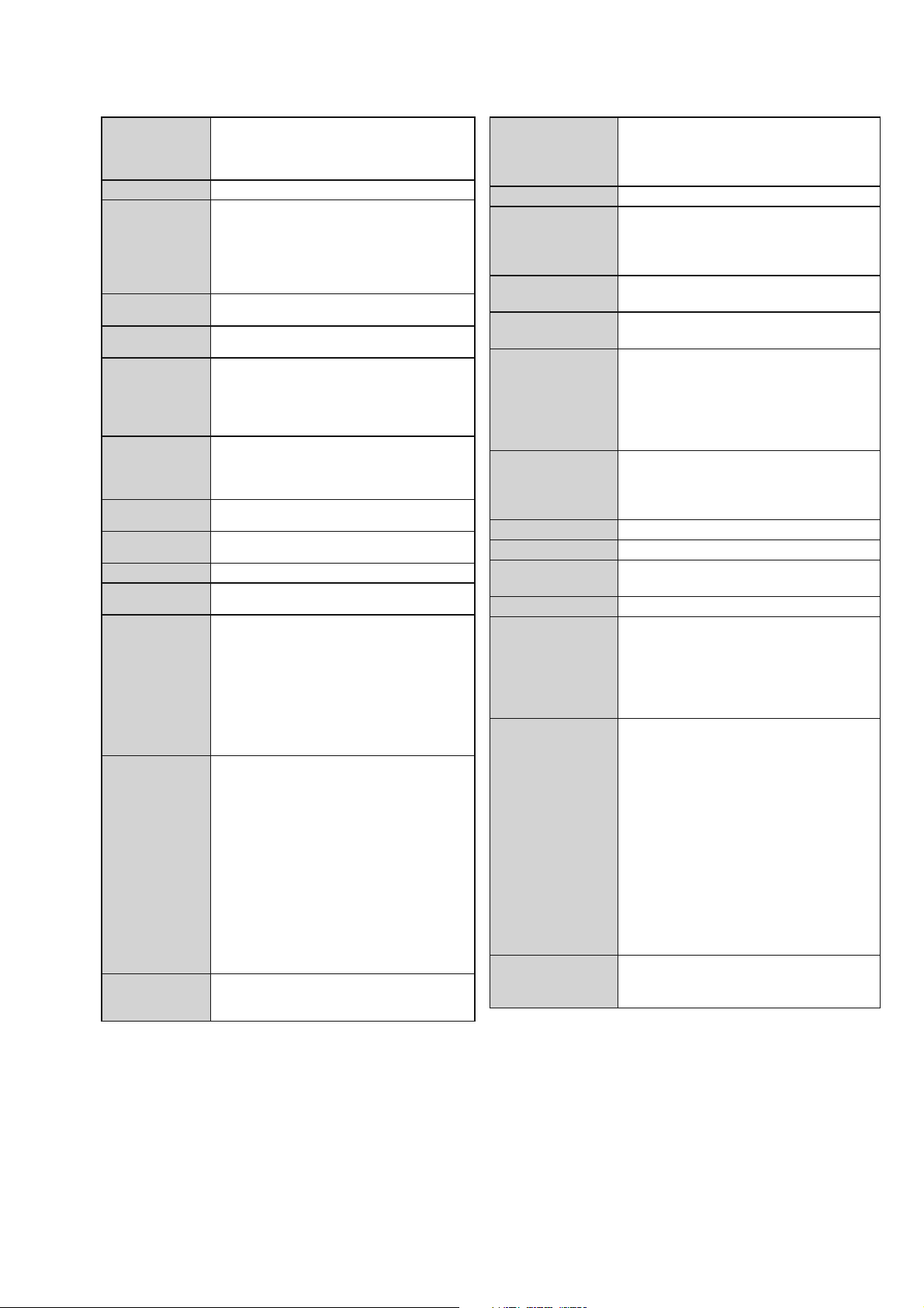
1. TECHNICAL SPECIFICATIONS
Display
3.7 inch TFT color display with touch screen
VGA (640 x 480 pixels) resolution landscape
LCD
65,536 colors
Interface
USB 2.0 port connector
Infrared (IR) • Operating distance = max 12 m (36 ft)
• Learning distance = 100-150 mm (3,9 −
5,9 inch) at 0-40 degrees
• Operating angle= 45° at max 5 m (15 ft)
• Operating/ learning frequency range =
17 kHz − 1 MHz carrier freq
Wireless System WiFi based technology operating at 2.4
GHz
Memory 64 MB SDRAM
64 MB NAND Flash
Power
Management
• Power on by tilting, tapping the screen,
pressing the backlight button or tapping
the keys
• Power off automatically by time out
• Battery status indication
Dimensions Control Panel: 166,4 x 100 x 32 mm (6.6
x 3.9 x 1.3 inch)
Docking Station: 130.5 x 98.7 x 61.3 mm
(5.1 x 3.9 x 2.4 inch)
Operating
Temperature
Storage
temperature
Battery
5° C − 45° C (41° F − 113° F)
-25° C − 70° C (-13° F − 158° F)
Lithium Polymer battery, 2100 mAh
Power Adapter 100 V-240 V AC / 50-60 Hz Power adapter
(5 V DC/2A output)
Accessories • USB cable . Power adapter
• Docking station
• CD-ROM with Wizz.it Ex, User Guides
for the Control Panel and Extenders
(PDF), Acrobat Reader
• 1 User Guide, "Installing and
Configuring"
• Warranty certificate (For USA/Canada
only)
Wizz.it Ex Supported operating systems :
• Windows 2000
• Windows XP
• Windows Vista
Minimum requirements:
• 500 MHz Intel Pentium III workstation or
equivalent
• 256 MB physical memory
• 250 MB of free disk space
Recommended requirements:
• 1.2 GHz Intel Pentium IV workstation or
equivalent
• 512 MB physical memory
• 500 MB of free disk space
IR code
database
information
Designed with UEI Technology
Licensed under U.S. Patent 5,689,353
Portions © UEI 1999
ディスプレイ 3.7インチ TFTカラー・タッチスクリーン・
液晶ディスプレイ
解像度:
640 x 480ピクセル横画面(VGA)、
65536色
インターフェイス
赤外線(
IR) 到達可能距離:12m(最大)
ワイヤレスシステム 使用周波数:2.4GHz WiFi(IEEE802.11b/g
内蔵メモリ
パワーマネージメント
USB2.0ポートコネクター
学習可能距離:
到達可能角度:
学習可能キャリア周波数:
準拠)
100〜150mm(0〜40°時)
45°(5m時)
64MB SDRAM
64MB NAND
フラッシュメモリ
• バッテリーセーブ
17kHz〜1MHz
チルト(傾き)センサー、スクリーンへの
タッチ、バックライトボタンまたはボタ
ン入力による電源オン。設定経過時間後
の自動電源オフ
• 充電池の残量表示
外径寸法 リモートコントローラー:
166.4 x 100 x
32mm
ドッキングステーション:130.5 x 98.7 x
61.3mm
動作温度 5°C〜45°C
保管温度 -25°C〜70°C
電池 リチウムイオン電池(リチウムポリマー電
2100mAh
池)、
電源アダプター 100V AC/50 〜 60Hz(5V DC / 2A出力)
付属品
• USBケーブル
• ACアダプター
• ドッキングステーション
• CD-ROM
取扱説明書
•
• 保証書
Wizz.it Ex サポートするオペレーティングシステム:
• Windows 2000
• Windows XP
• Windows Vista
最小システム要件:
• 500MHzのIntel Pentium IIIワークステー
ションまたは同等品
• 256MBの物理メモリ
• 250MBの空き容量
推奨システム要件:
• 1.2GHzのIntel Pentium IVワークステー
ションまたは同等品
• 512MBの物理メモリ
• 500MBの空き容量
IRコード
データベース情報
UEI Technology
ライセンス取得:米国特許 5,689,353
© UEI 1999
Reset (The Control Panel behaves erratically)
Normally, resetting the Control Panel is not necessary.
However, if the touch screen freezes or if you notice unusual
behavior, you need to perform a reset to get it running again.
You reset the Control Panel by switching the Power switch
to 0, waiting a few seconds and switching the Power switch
back to 1.
リセットの方法
通常、本機のリセットは必要ありません。ただし、タッチスクリ
ーンがフリーズした場合や、異常な挙動がみられる場合は、リセ
ットしてください。
本機のリセットは、電源スイッチを「
電源スイッチを「
」表示が消えるまで、何もしないでください。
wait ...
1」に戻します。再起動後、画面の「please
0」に切り替え、数秒後に、
1
Page 4
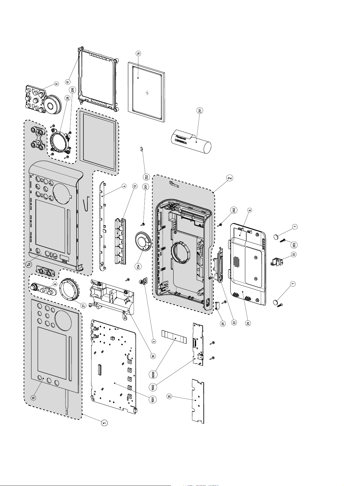
2. EXPLODED VIEW
2
Page 5
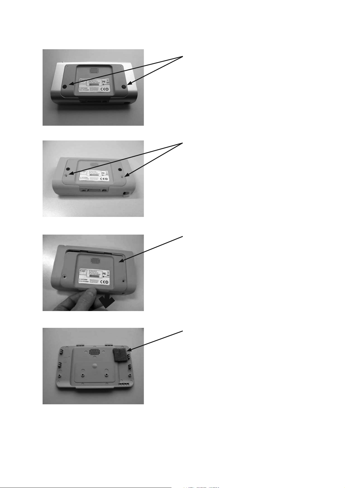
3. MECHANICAL INSTRUCTIONS & SET DISASSEMBLY
Remove rubber feet ITEM 7 to make the screw accessible.
1
Remove screw ITEM 203 (Torx screw M2x10).
2
3
Remove the bottompart cover assy ITEM 20 by sliding it
open
Location of adhesive damper ITEM 6 to prevent rattling of
battery pack
4
3
Page 6
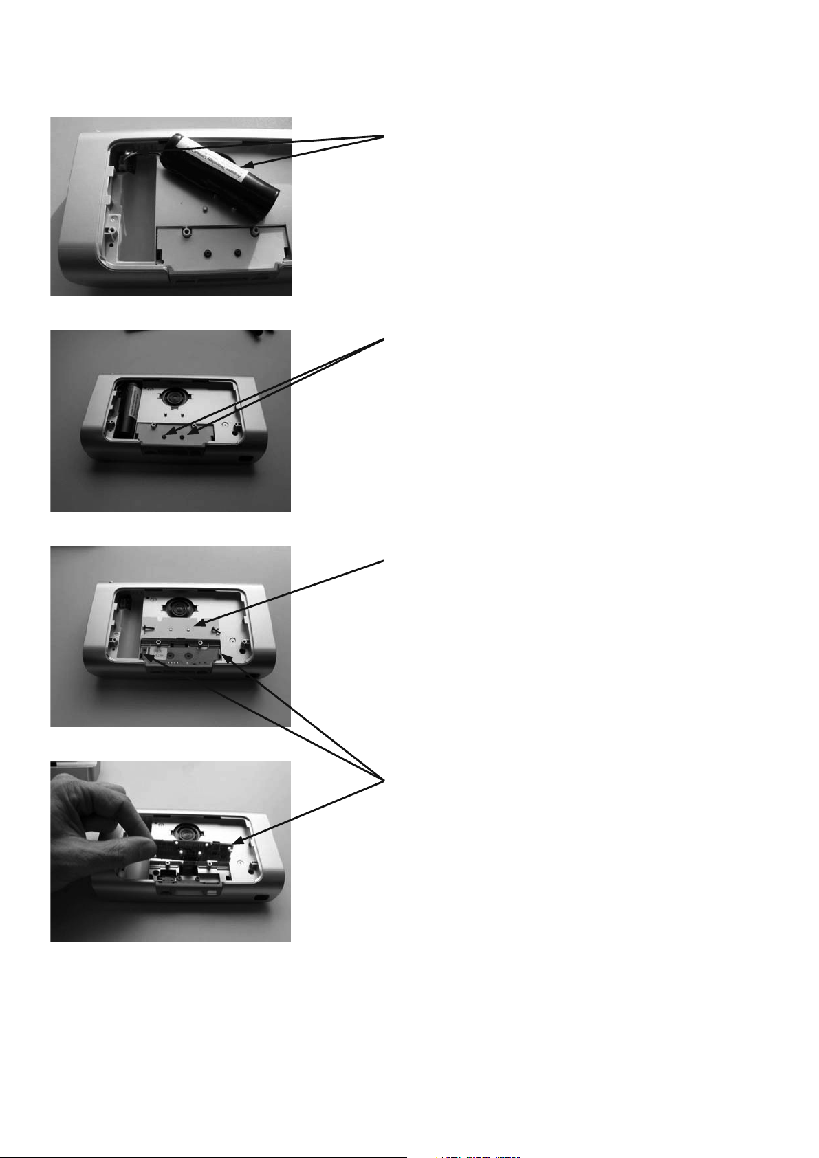
5
6
Take the battery out, ITEM 251, disconnect battery
connector
NOTE: To close the unit go to P….
Battery replacement set:
ITEM 251 (1x) battery
ITEM 7 (2x) rubber feets
Remove screw M2x8 ITEM 202
7
8
Take away 2 screw M2x8 ITEM 202 and pwb cover ITEM 35
Release two snaphooks and take the SUB PWB ITEM 1002
4
Page 7
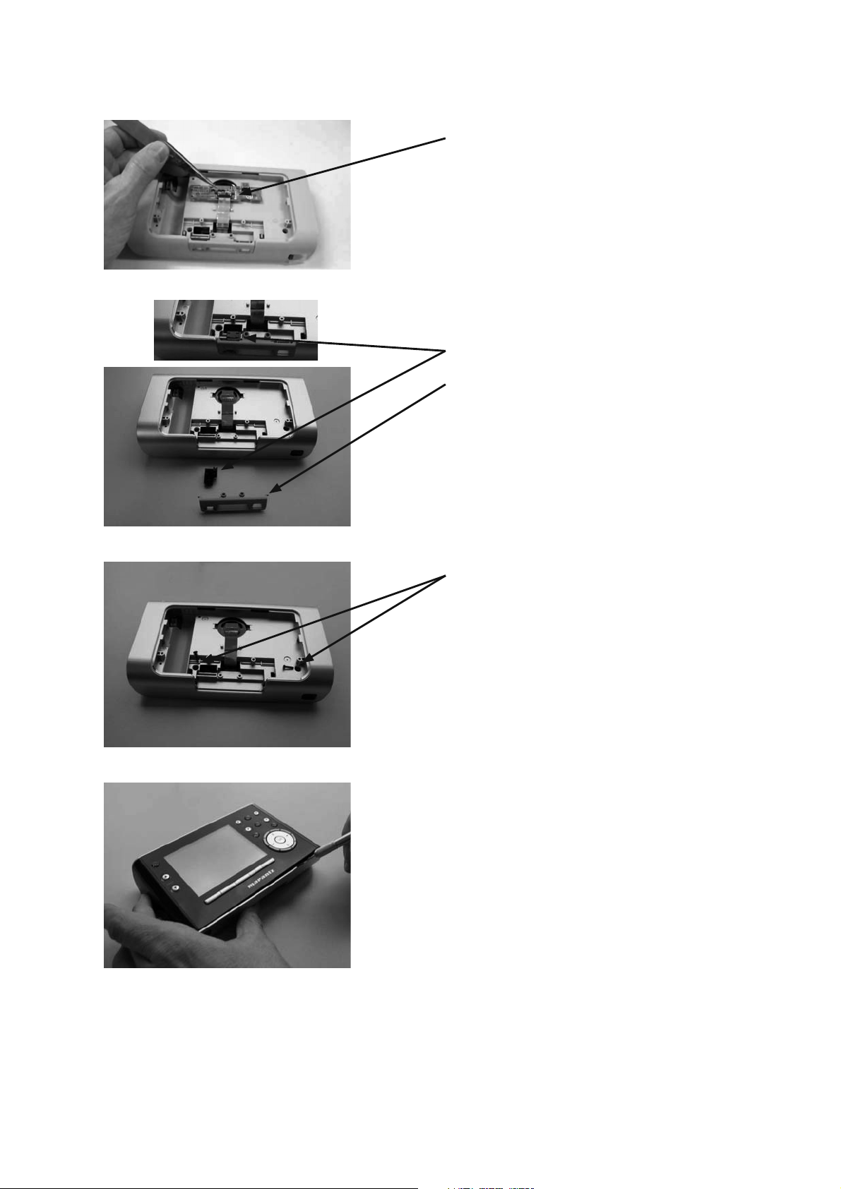
9
10
Disconnect SUB PWB ASSY ITEM 1002 to release the flex-
cable (unlock connector 1003 with the help of a pincet).
On-off switch ITEM 33 take out of the bottom
Docking insert assy ITEM 22 take out of the bottom
11
12
Remove 2 screw ITEM 202 (Torx screw M2X8) on the
position as shown in the picture
Release bottompart (item 02) from toppart (item 01) and
goes from the rightside to the leftside.
Very important is to start up with one of the "sides" as
shown in the picture (Photo 13-15).
- Put a sharp knife between toppart and bottompart and
use this as a lever to separate the two parts.
- Important: push up the bottompart compared with
the toppart to unlock the plastic snaps in the holes
(bottompart).
5
Page 8
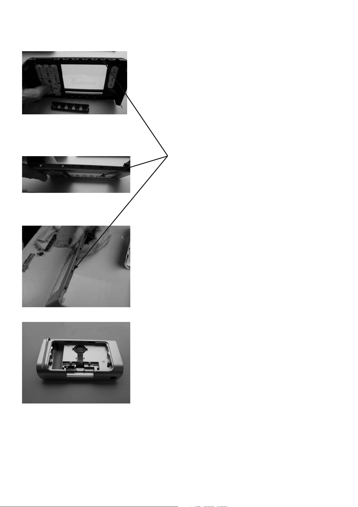
13
14
Overview of different snapholes in toppart assy (for
information only)
15
16
Take the toppart assy and place it on the table
6
Page 9
17
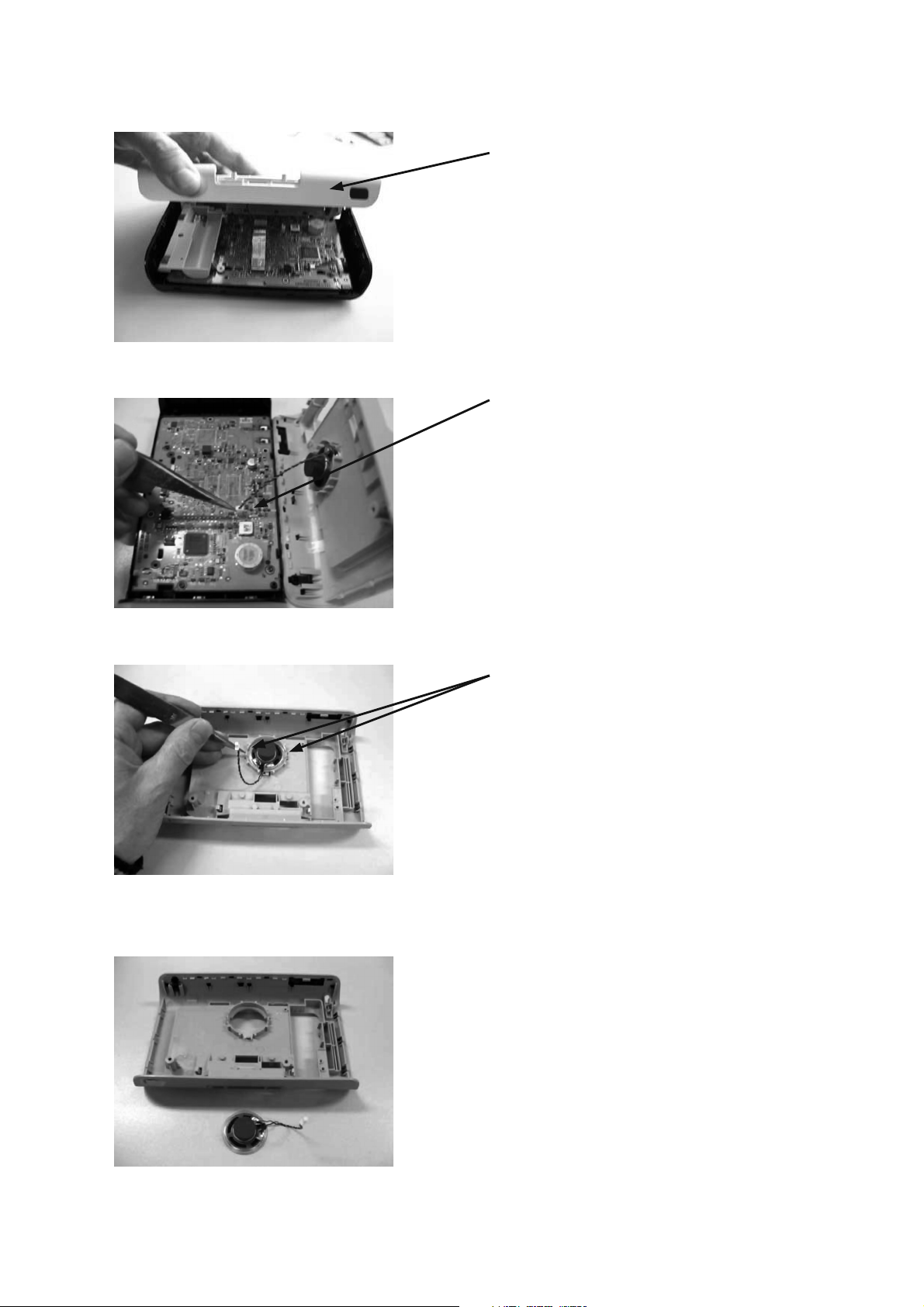
Open the bottompart assy from the toppart and place it also
on the table, see next picture
Disconnect the speaker plug (connector 1601)
18
19
Lift the 2 snaphooks fom the speaker
20
7
Page 10

21
22
IR-WINDOW
Remove IR- Window
BACKLIGHT BUTTON
Remove backlight button
23
24
Remove 2 screw M2X8 ITEM 202
Touchpad connector ITEM 10 to release the flexcable
(unlock connector …. with the help of a pincet
Click two times from left side to right side
25
8
Page 11

26
27
Remove 3 screw M2X8 ITEM 202
Remove MAIN PWB assy ITEM 1001
28
Remove the following components from the
toppart sub assy ITEM 1
Keymat stand by assy ITEM 8
Keymat cursor assy ITEM 9
Lower keyhinge assy ITEM 13
9
Page 12

29
Be carefully: ITEM 1a + ITEM 10
Toppart sub assy + tochscreen preserve this subsam assy
for the rest untouched !! Don’t remove anything else as
mentioned in this list
Remove cursor ring assy ITEM 27
Remove cursor holder ITEM 28
Remove screw M2x4 ITEM 200
Overview mechanical toppart components
30
10
Page 13

Overview mechanical components
11
31
Page 14

4. MECHANICAL INSTRUCTIONS & SET RE-ASSEMBLY
ITEM 17 LCD bezel + ITEM 16 LCD module
32
Release the LCD bezel ITEM 17 from PB 1001, push
downwards to unlock the 4 plastic snaps in the snap holes
33
34
Release the flex cable from LCD ITEM 16 to unlock the
connector 1401 by till up the lid from connector 1401 (90
degrees), and take the LCD module out the LCD bezel ITEM
17
For LCD re-assembling use the opposite sequence order
and finally lock connector 1401 by pushing the lid from
connector 1401 down again
LCD module ITEM 16
35
LCD bezel ITEM 17
12
Page 15

SUBSAM TOUCHSCREEN SERVICE
For service people, the toppart (item 01) same with the
touchscreen (item 10) is already prepared as “subsam part”
an can be ordered under the codenumber 3104 207 15770
In case of replacement follow the instructions Set Re-
assembly on page 3-1
36
37
ASSEMBLE INSTRUCTIONS
Toppart
1. Cursor placement
1. Take toppart assy ITEM 01
2. Mount Cursor ring ITEM 27
3. Mount Cursor holder ITEM 28
4. Add 2 screw (Torx M2X4) on the position as shown on
the picture
Cursor ring assy ITEM 27
38
Cursor holder ITEM 28
2 screw M2X4 ITEM 200
13
Page 16

39
2. Key placement
Keymat cursor ITEM 9
Keymat stby ITEM 8
Lower key hinge ITEM 8
(Spring cursor ring)
3. LCD + Bezel placement
ITEM 16 LCD module
ITEM 17 LCD bezel
40
41
4. LCD flex placement
Place the flex of the LCD perfectly into the connector and
close them
5. LCD placement
Mount the 4 snaphooks of the LCD on the hole of the MAIN
PWB ASSY
42
43
14
Page 17

44
Push with your finger the left and the right snaphooks into
the pwb assy
Mount 3 screw M2x8 ITEM 202
45
6. Flex placement
Place the flex into the connector and close them with a pincet
46 47
2. Bottompart
48 49
Mount speaker into the bottom and click on the two snaphooks
Backlight key ITEM 5
15
Page 18

50
3. Toppart + Bottompart
Click the connector of the speaker on the MAIN PWB assy
Place the bottom on the top don’t forget the flex
Place the 2 screw M2X8 ITEM 202
51
52
Place the flexcable into the hole of the bottom
Click the bottom on the top
53
16
Page 19

54
55
Place the On-off switch
Place the docking insert assy
56
Place the flex into the connector and close them with a
pincet
Place the pwb into the bottom Push the flex into the hole
Click the SUB PWB ASSY into the two snaphooks
57
17
Page 20

58
Place the SUB PWB cover ITEM 35
Place screws M2x8 ITEM 202
Place the connector on the MAIN PWB ASSY and put
batterypack into the hole
59
60
Place the Bottom cover assy
Place the screw M2x10 ITEM 203
61
18
Page 21

62
63
Place the new rubber foots ITEM 7
Place IR-window assy ITEM 4 and push it into the different
clickhooks
64
Place pen assy ITEM 93 into the hole
19
Page 22

5. PARTS LIST
(
)
(MZ)
(
p
/
p
p
/
/
/
p
/
M
/
p
p
/
/
/
p
P.C.B.
NAME
PACKING
POS. NO.
VERS.
COLOR
PART NO.
FOR EUR
PART NO.
PART NAME DESCRIPTION
1 00M28CW064510 00M28CW064510 CASE ASSY SUBSAM TOUCHSCREEN SERV_RC9001 310420715771
2 00M28CW064520 00M28CW064520 CASE ASSY BOTTOMPART ASSY_RC9001 310420782302
4 00M28CW158020 00M28CW158020 WINDOW IR WINDOW ASSY_RC9001 310420782392
5 00M28CW270060 00M28CW270060 BUTTON BACKLIGHT KEY ASSY_RC9001 310420782310
6 00M28CW056410 00M28CW056410 BUFFER DAMPER 310420412561
7 00M28CW057410 00M28CW057410 LEG RUBBER FEET 313922420711
8 00M28CW270510 00M28CW270510 BUTTON KEYMAT STDBY ASSY_RC9001 310420782322
9 00M28CW270520 00M28CW270520 BUTTON KEYMAT CURSOR ASSY_RC9001 310420782332
13 00M28CW270050 00M28CW270050 BUTTON LOWER KEY HINGE ASSY_RC9001 310420782351
16 90M-KZ000080R 90M-KZ000080R LCD KIT LCD MODULE LS037V3DX01
SRPJ)Y 932223258682
17 00M28CW271420 00M28CW271420 HOLDER LCD BEZEL 310420421944
20 00M28CW257010 00M28CW257010 LID BOTTOMPART COVER ASSY_RC9001 310420782362
22 00M28CW053010 00M28CW053010 COVER DOCKING INSERT ASSY_RC9001 310420782371
27 00M28CW355410 00M28CW355410 RING CURSOR RING ASSY_RC9001 310420782381
28 00M28CW271410 00M28CW271410 HOLDER CURSOR HOLDER 310420421934
29 00M28CW158030 00M28CW158030 WINDOW IR WINDOW_RC9001 310420422481
30 00M28CW271010 00M28CW271010 HOLDER BATTERY PACK HOLDER_RC9001 310420422501
33 00M28CW154010 00M28CW154010 KNOB ON-OFF SWITCH_RC9001 310420422461
35 00M28CW120010 00M28CW120010 INSULATOR PWB COVER_RC9001 310420422271
93 00M28CW254010 00M28CW254010 STYLUS PEN PEN ASSY_RC9001 310420782412
251 90M-ZF000050R 90M-ZF000050R BATTERY BAT PACK LIP 3V7 2200MAH Y 242252600183
254 90M-QK000300R 90M-QK000300R SPEAKER LSP 8R 0W5 OPN FULR R32 Y 242226400594
676 00M28CW861410 00M28CW861410 LABEL APPROB. STICKER_RC9001 310420007201
999 90M-ZK000730R 90M-ZK000730R UNIT KIT DOCKING STAT. MAR SERV_DS9001 310420715801
1001 90M-ZZ004680R 90M-ZZ004680R PWB ASSY PWB ASSY MAR MAIN SERV_RC9001 310420715781
1002 90M-ZZ004690R 90M-ZZ004690R PWB ASSY PWB ASSY MAR SUB SERV_RC9001 310420715791
8000 ns
001T
A1S ns
001T F S ns
001T
001T
001T
005T
N1S 00M28CW851250 00M28CW851250 USER GUIDE USER GUIDE RC9001 U A 310420534381
T1S 00M28CW851250 00M28CW851250 USER GUIDE USER GUIDE RC9001 U A 310420534381
U1S ns
N1S 00M28CW851310 00M28CW851310 USER GUIDE USER GUIDE RC9001 N T 310420534391
00M28CW851010 00M28CW851010 USER GUIDE MULTI LANGUAGE USER GUIDE CD-RO
A1S ns
F S ns
90M-YU003040R FPC FFC20P/50/20P/0.5 B 310420052601
00M28CW851250 USER GUIDE USER GUIDE RC9001 U A 310420534381
00M28CW851110 USER GUIDE USER GUIDE RC9001 F -
00M28CW851250 USER GUIDE USER GUIDE RC9001 U A 310420534381
310420910331
90M-AA000160R AC ADAPTOR AC/DC ADAPTOR AY3192/10 A1S 314017830062
90M-AA000150R AC ADAPTOR AC/DC ADAPTOR AY3192/17 JAPAN & US 272201200635
N1S 90M-AA000130R 90M-AA000130R AC ADAPTOR AC/DC ADAPTOR AY3192/00 N1S 314011833803
T1S 90M-AA000140R 90M-AA000140R AC ADAPTOR AC/DC ADAPTOR AY3192/05 T1S 314011833812
U1S ns
90M-AA000150R AC ADAPTOR AC/DC ADAPTOR AY3192/17 JAPAN & US 272201200635
NOTE : "nsp" PART IS LISTED FOR REFERENCE ONLY, MARANTZ WILL NOT SUPPLY THESE PARTS.
20
Page 23

For reference only
DS9001
Docking Station
POS. NO. 999 PART NO. 90M-ZK000730R UNIT KIT
21
Page 24

EXPLODED VIEW
The following parts are not supplied as service parts.
下記部品のサービス部品供給はありません。
22
Page 25

MECHANICAL INSTRUCTIONS & SET DISASSEMBLY
Docking station
ITEM 34: Push on the left side to the standplate and remove
it
Remove rubber foot to make the screws accesible ITEM 7
Remove screw ITEM 201
23
Page 26

ITEM 36 Go with a pincet to the rubberstrip and the plastic
and remove them
Remove screw ITEM 201 and take away the rubber strip
Remove screw ITEM 201 and take away the rubber strip
Release bottompart from the toppart
24
Page 27

Remove the lightguide ITEM 21
Remove srew ITEM 0201
PWB ASSY ITEM 1001
FLEXCABLE ITEM 8000
PWB ASSY ITEM 1002
25
 Loading...