

Page 1

S
al
UNIVERSAL HOME THEATER Remote control
RC3200
RC3200/U1S
RC3200/M1S
ervice Manu
/A
TABLE OF CONTENTS
Chapter
Specification / Service hints ...................................................... 1
Dismantling hints ..................................................................... 2
Circuit description ..................................................................... 3
Troubleshooting ....................................................................... 4
Electrical diagram .................................................................... 5
Assembly diagram ..................................................................... 6
Exploded view ........................................................................... 7
Partslist ................................................................................... 8
© Royal Philips Electronics NV
All rights are reserved. Reproduction in whole or in part is prohibited
without the prior written consent of the copyright owner.
Published by MD 0312 RCS Service Subject to modification 3104 205 5002.3
marantz
Page 2

1-1
SPECIFICATIONS
Display Monochrome touch screen LCD with 4 gray levels and
digital contrast control.
Resolution: 160 x 100 pixels
Blue EL backlighting for LCD and hard buttons
Interface 3-wire (RS232) serial port connector
Software Built-in Marantz RC codes
Total number of devices limited only by memory
Infrared (IR) Infrared sending LED and learning eye
Operating distance of 33 feet (10 meters)
Learning frequency up to 56 kHz and 455 kHz
Learning distance 1 inch (2 cm) up to 4 inch (10 cm)
2-way communication with specific marantz equipment
Memory 1 MB non-volatile flash memory
Batteries 3 AA-batteries (3 x 1,5V): primary or rechargeable
Power management Power on by tapping the LCD touch screen or by pressing
the Backlight button
Power off automatically
Dimensions 7.8 inch x 3 inch x 1.3 inch (177mm x 74mm x 33mm)
Operating temperature 41°F to 1 13°F (5°C to 45°C)
Accessories only for RC3200/U1S/M1S only RS3200/A
RS232 cable for PC connection None
IFU RC3200
3 AA-batteries
SERVICE HINTS
-RC3200 information
Press and hold the Mode button for 3 seconds -Tap SETUP - go to page3/3 with page up or page down button.
This page contains following information:
Free memory :
Boot version :
System version :
Application version :
Configuration file :
-Cleaning RC3200
Use a soft, damp cloth to clean the RC3200
If the LCD touch screen is dirty, clean it with a soft cloth moistened with a diluted window-cleaning solution.
After a repair please make the LCD touch screen always clean !
-Update the RC3200
Please check after each repair the RC300 application version.
Check the version on the website. Is the version higher on the website, please download the new version from
the Firmware.
You can find this on the Marantz website http://www.marantz.com
Page 3
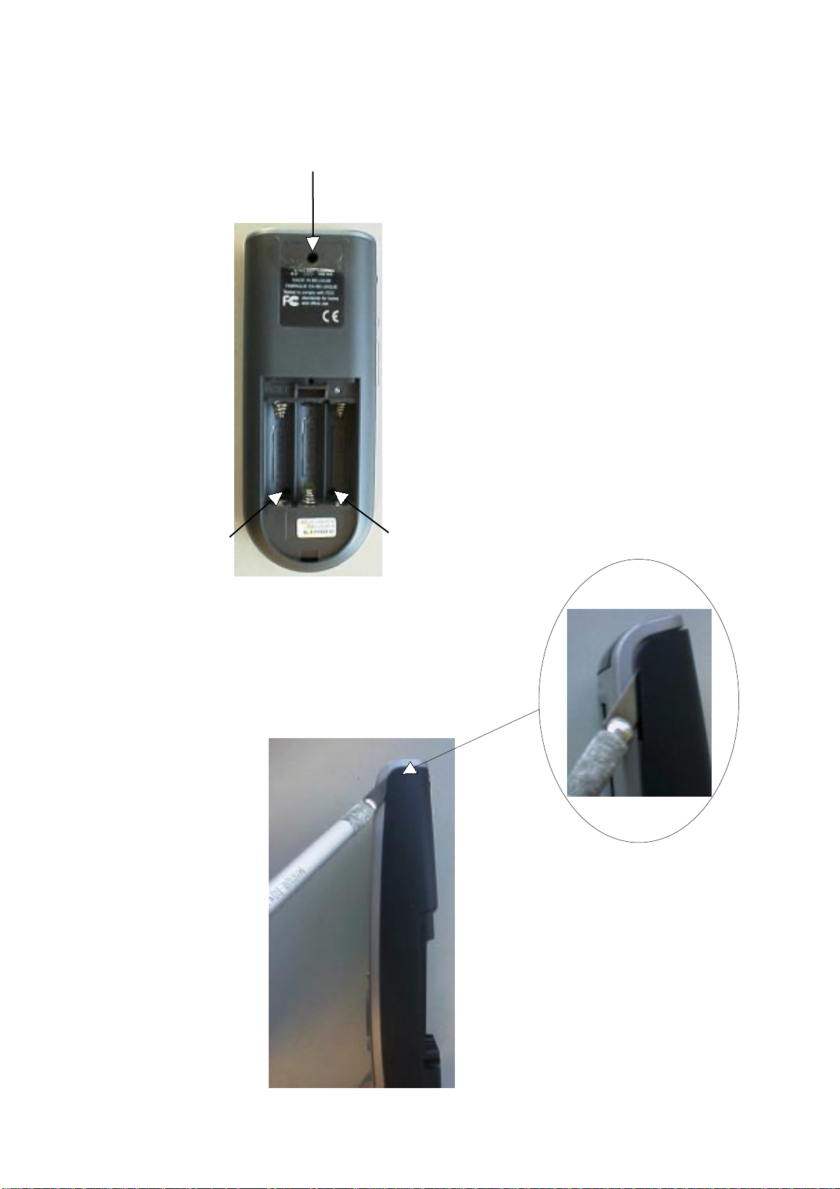
DISMANTLING HINTS
1. Remove battery lid
2. Remove label a little. see picture1
3. Remove 3 x screw as shown in picture 1
2 x 8mm
2-1
2 x 8mm
2 x 8mm
picture 1
4. Put a sharp knife between toppart and bottompart
and use this as lever to separate the two parts. see picture 2
picture 2
Page 4

3-1
CIRCUIT DESCRIPTION
1 Power supply
Components: 7201
The power supply makes use of the LT1761 low drop linear regulator of Linear Technologies. The output voltage is 3.3V.
2 Reset & delayed reset.
Components: -reset: 7202
-delayed reset: around 7203, 7204
The S-809 (Panasonic) detects the hardware reset level of the batteries. Below this level (2.8V) reset is passed to the
“delayed reset” circuit.
The “delayed reset circuit” is activated by the S-809 or the reset switch 1203. It will delay the reset signal by approx. 80ms and
has a hysteresis of 200mV
3 Battery level measurement
Components: around 7206, 7207
The battery voltage is measured via a 1:2 divider by the master microcontroller. This divider is switched on/off by the master
by means of 7206 and 7207.
4 EL-foil driver
Components: around 7205
The EL-sheet is driven by the D371 (Durel). This component generates a high-voltage semi sinewave by switching a coil of
2.2mH. It contains 2 oscillators: a high-frequency oscillator switching into the inductor at approx. 17kHz. A low-frequency
oscilator drives the EL-sheet at approx. 500Hz. The EL-sheet is driven with approx. 75Vpeak.
Zener diodes 6208 and 6209 limit the sinewave voltage when no sheet is attached (during repair of the unit).
5 +/- 17V generator
Components: around 7210
The + and - 17V are generated by the MC64063A, a DC-to-DC converter who is used in a step-up configuration.
The switching frequency ranges up to 150kHz (depending on the load) with ringing on the edges of approx. 3MHz.
The generator is switched on/off via 7208 and 7209 from the master microcontroller.
6 Master microcontroller & memories
Components: 7101, 7115, 7103, 7102
The master is the main microcontroller in the system (M30800, Mitsubishi). It uses external flash program memory
(AM29LV800BT, AMD) and SRAM (CY62256V, Cypress). Address selection is performed with 74LV139.
The master runs from two crystals: 7.3728MHz, onlu runing when active. The other crystal of 32.768kHz is always running,
even in sleep mode.
7 Buzzer
Components: around 1103
The sound function is made by a piezo-electric buzzer. The steering frequency range is 200Hz ~ 8kHz.
8 RS232 transmitter
Components: around 7105, 7106
This circuit converts the RS232 outgoing signal from the master between 0 and 3.3V to -15 and +15V levels.
RS232 communication is set at 115kBaud both directions.
9 RS232 receiver & detection.
Components: around 7107, 7108, 7109
Transistor 7107 converts the incoming RS232 signals between -/+15V into 0-3V levels towards the master.
Transistors 7108 and 7109 perform a RS232 incoming signal detection and interrupt the master during sleep mode when
communication starts from a connected PC.
10 Touchscreen.
Components: around 7111, 7112, 7113, 7114
A resistive touchscreen is used, composed of two layers of resistive material. Pressing the screen causes a short-circuit
between the two layers.
The touchscreen is operated in two steps:
1. detection of a touch
2. reading of the actual position of the touch
Detection is done by connecting one layer to ground and the second layer to 3.3V with a pull-up resistor. The voltage on the
second layer will change from 3.3V to 0V when touching.
Readout is performed in 2 phases, each determining one coordinate.
First, layer 1 is connected between 3V3 and ground. The potentiometric position of the touch location can be read by
measuring the voltage on the layer 2.
The other coordinate is read by interchanging the layers in previous procedure.
Page 5

3-2
CIRCUIT DESCRIPTION
11 LCD
Components: 1101
The LCD module (Wintek) is a STN type 100x160 pixel including the driver HD66421 of Hitachi. The touchscreen is glued on
top the the LCD module.
The LCD module uses a 8 bit bus directly iterfacing to the databus of the master.
It uses two voltages: 3.3V for the logic and 17V for the LCD glass drive.
The LCD driver uses a clock of approx. 190kHz to generate all timing.
12 Keyboard
Components: 0102, etc...
The keyboard is a matrix of 6 x 3 keys. It is static when no key is pressed, and scanned when a key is applied.
13 Slave microcontroller
Components: 7301
The slave microcontroller M37540M4 (Mitsubishi) takes most of the real-time functions: IR-sending, IR learning and steering
the database microcontroller.
Sending IR is performed via pins 28 and 29, combining envelope and carrier with AND-gate 7302.
Transistors 7303 and 7304 combine the IR-sending signals from slave uC and database uC towards the IR-transmitter circuit.
The salve uC also switches on/off the power of the learing circuit via 7305.
Bidirectional communication to the master uC goes via a UART at 57kBaud.
Communication to the database uC goes via a 3-line dedicated bus.
14 Infrared transmitter
Components: around 7307, 7308
The IR-transmitter transmits any IR-code coming from slave or database uC.
It steers two IR-transmission diodes with a peak current of approx. 300mA in each of them.
The IR-diodes transmit invisible infrared light at 940 nm in an angle of 2 x 25 degr.
An electrolytic capacitor of 100uF smoothen-out the carrier frequency in order to have only the average current flowing from
the batteries (envelope of the IR-code).
There are many many brands with each several IR-codes. Basically, all codes consist of a low bitrate burst (around 1kbit or
slower) modulated on a carrier of 30 - 60kHz, and repeated at a rate of 5 - 20Hz.
15 Learning circuit
Components: around 7309, 7310
This circuit is used for learning IR-codes. It uses signals captured by the IR-transmission LEDs 6301and 6302. Transistor
7309 amplifies the signal. Opamp LM393-B puts a minimum threshold and amplifies further. The output of LM393-B contains
the carrir frequency and is fed to the slave IC for carrier frequency measurement. The output is also fed onto a detector. This
has a time constant suitable to detect to the envelope signal of the IR-code. Opamp LM393-A cleans up and its output is fed
also into the slave uC for envelope recording.
16 IR - Receiver
Infrared receptor 6306 and surrounding components
17 Not impemented functions (in circuit diagram)
Some of the parts in the circuit diagram are actually not stuffed on the board.
RS transmitter module 1301
Overview of frequencies
EL-foil driver D371A: 17kHz, 500Hz (75Vpeak)
+/-17V generator: 150kHz, 3MHz ringing
crystals master uC: 7.3728MHz, 32.768kHz
resonator slave uC: 3.64MHz
resonator database uC: 4MHz
RS232 speed: 115kBaud
baudrate between master & slave uP: 57.6kBaud
LCD internal clock: 190kHz
IR-transmission: carrier frequencies: approx. 30 - 60kHz
List of EMC-critical components
Critical components for EMC are:
· The EL-foil generator (high voltage)
· All crystals
· The data & address busses of the master uC to the Flash, SRAM and LCD module
· The IR-transmitter (high current)
Page 6

4-1
TROUBLESHOOTING
General Problems
The display stays blank or becomes black
• Make sure the batteries are properly installed.
• Press the Backlight button to make sure RC3200 and the backlight are
turned on.See ‘Turning on the Display and the Backlight’
• Adjust the contrast using the Backlight button and the Page Up or Page Downbuttons on the left side of RC3200 See
‘Changing the LCD Contrast’
The display is too light or too dark
• Adjust the contrast using the Backlight button and the Page Up or Page Down buttons on the left side of RC3200. See
‘Changing the LCD Contrast’
RC3200 shuts off automatically
• This is a timeout feature of the RC3200 to save power. You can change the time RC3200 stays on in the Settings.See
‘Adjust the LCD Timeout’
Devices do not respond to commands from RC3200
• Make sure RC3200 is in Use mode. See ‘Working with Modes’
• Make sure RC3200’s sending LED is pointed towards the device you’re operating.
• Check if the battery level is low. If so, replace the batteries.
• Check that you have correctly learned the IR commands. See ‘Tricks for Remote Controls that are “Difficult”’
• If the button is programmed with a macro, and all other buttons are working correctly, reprogram the macro See‘Recording
Macros’
RC3200 does not learn commands from an existing remote control
• Do not learn commands directly under fluorescent lights.
• Do not learn commands on a reflecting table surface.
• Check if the battery level is low. If so, replace the batteries.
RC3200 is not recognized by the RC3200 Setup Programmimg Software software
• Make sure the serial cable is properly connected. See ‘RC3200 Setup Programming Software’
• Disconnect other equipment connected to the serial ports, e.g. PDA’s.
• Plug the serial cable in another serial port.
• Try to connect multiple times.
Programming Problems
Buttons are not sending the correct commands
• Check whether the button of the device is learned properly. See ‘Learning From Other Remotes’
• Check whether the macro is recorded properly. See ‘Recording Macros’
RC3200 will not switch modes
• Replace the batteries. When the batteries are low RC3200 prevents you from switching to customizing modes so that no
customization can get lost.
RC3200 is low on memory
• Revert the RC3200. See ‘Revert’
The configuration file is corrupted
• When this unlikely event occurs, you have to revert to the original configuration or use RC3200 Setup Programming
Software to download a new configuration file. All your customized commands and devices will be lost and you will have to
reprogram your RC3200. If you use RC3200 Setup Programming Software, it is advised to make backup copies of your
customized configurations. See ‘Revert’ and ‘RC3200 Setup Programming Software’
RC3200 error message
If the error message ‘Invalid CF version or corrupt Flash!’ occurs:
• Use the Reset button on the back of the RC3200. See ‘How do I reset the RC3200?’
• Try to recover the RC3200 Configuration File (NCF) by downloading a backup copy or the default file from RC3200 Setup
Programming Software. See ‘RC3200 Setup Programming Software’
• Go to the Marantz website http://www.marantz.com for more information.
- Turning on the Display and the Backlight
RC3200’s display can be activated in three different ways:
Tap the touch screen gently with your finger or a blunt, soft object like a pencil eraser.
The display is activated. Press any button on the RC3200.
The display is activated. Press the Backlight button on the left side of the RC3200.
The display and the backlight are activated.
If the LCD touch screen stays blank or becomes black when turning on the display, read the next section ‘Changing the LCD
Contrast’ to adjust the contrast of the LCD touch screen.
Note: RC3200 has a timeout feature: the LCD touch screen and the backlight
automatically turn off to save power. See ‘Adjusting the Settings’ to adjust the timeout for the LCD and the backlight.
Page 7

4-2
TROUBLESHOOTING
- Changing the LCD Contrast
To adjust the LCD contrast on the touch screen:
1 Press and hold the Backlight button.
The screen lights up.
2 While still holding the Backlight button, press the Page Up button once
to increase the LCD contrast one level.
The LCD contrast is adjusted one level up.
–or–
Press the Page Down button once to decrease the LCD contrast one
level.
The LCD contrast is adjusted one level down.
3 Release the Backlight button when the contrast is satisfactory.
The LCD contrast can be adjusted 16 levels.
Note: To adjust the contrast multiple levels, you have press the Page Up or Page Down button multiple times. When you press
and hold the Page Up or Page Down button, the LCD contrast will only change one level.
- Operating Devices
To operate devices on your RC3200 you have to switch to the Device overview. This screen displays the available devices like
TV, VCR, DVD, PreAmp and so on.
- Adjusting the Settings
The RC3200 settings can be adjusted in the Setup mode.
Press and hold the Mode button for 3 seconds.
- Adjust the LCD Timeout
The LCD timeout indicates how long the LCD touch screen stays active before it turns off. The LCD will only time out when
you don’t touch any buttons. You can set the timeout between 1 second and 120 seconds.
Press ‘+’ to increase or ‘-’ to decrease the time the LCD stays active.
Tap ‘+’ or ‘-’ once to adjust the timeout 1 second up or down.
Press and hold ‘+’ or ‘-’ to adjust the timeout per 10 seconds up or down.
- Working with Modes
RC3200 starts up in Use mode. In this mode you operate your devices. For customizing the RC3200 (adjusting the settings,
defining brands, learning buttons, labeling buttons and devices or recording macros) you have to switch to the appropriate
mode via the menu that appears when you press and hold the mode button.
The RC3200 can be put into 4 different modes. These modes are:
Use mode: Normal operating. See ‘Operating Devices’
Setup mode: For changing the RC3200 system settings. See ‘Adjusting the Settings’ for more details.
Learn mode: For learning commands from other remote controls. See ‘Learning Commands’ for more details.
Macro mode: For recording macros. You can assign multiple commands to one single button. See ‘Recording Macros’ for
more details.
Note :Learning commands and recording macros is not possible from either of the Home pages. You must select a device or
the Macro group first, then press and hold the Mode button perform.
- Learning From Other Remotes
If you own any non-Marantz components, you can program RC3200 to reproduce IR signals from your existing remote
controls via RC3200’s learning eye. To do this, place RC3200 and the device’s remote control on a flat surface, 1 to 4 inches
(2 to 10 cm) apart.
To learn commands from other remote controls, RC3200 has to be in Learn mode. Switching to Learn mode is only possible
from a specific device, not from the Home Page. See ‘Working with Modes’
Per device you can learn all soft and hard buttons on the RC3200, except for:
• the Backlight button;
• the Back and FWD buttons;
• the Page Up and Page Down buttons;
• the “S” (Status) button;
• the Home button.
The Learn Sequence
1 From the Home page, select the device, e.g. TV, with the buttons you want to teach new commands to.
2 Press and hold the Mode button for 3 seconds. The Mode screen appears.
3 Tap Learn on the Mode Menu. RC3200 is now in Learn Mode. ‘Learn’ and the label of the selected device appear at the top
of the touch screen.
4 Use, if necessary, the Page Up or Page Down button to go to the next button you want to learn.
5 Press the soft or hard button you want to learn on theRC3200. The Learn label changes to Learning, which means RC3200
is ready to receive commands from an existing remote control. The RC3200 will wait for 3 seconds to receive an IR code from
another remote control.
Note: When a hard button is pressed to learn, there is no on screen feedback to indicate which button is pressed.
Page 8

4-3
TROUBLESHOOTING
6 Press and hold the button on the existing remote control you want to learn to the RC3200.When the RC3200 receives an IR
code:
• You hear a confirmation beep;
• The label changes from Learning to OK. The Learn sequence has been successful. When the RC3200 does not receive an
IR code in 3 seconds:
• You will hear an error beep;
• The label changes from Learning to Failed. The Learn sequence has failed.
• RC3200 will return to Learn mode. Return to step 5 of the Learn sequence to relearn the button.
Tip You do not have to wait for the OK or Failed to disappear. If you press another button (soft or hard button), the RC3200
Learn sequence immediately goes back to step 5.
7 Go to other pages of the selected device with the Page Up and Page Down buttons. Repeat steps 6 and 7 until you have
copied all the commands of the existing remote control.
8 Press Done when you have finished learning commands to the buttons of your choice. RC3200 returns to Use Mode. You
can try out the new IR codes or select another device to learn.
- Recording Macros
A macro allows you to send a sequence of commands using one single button. You can for instance, switch on your TV, turn to
a movie channel and prepare your VCR for recording by rewinding the videotape. All this can be done be pressing a single
button on your RC3200.
To record macros, RC3200 has to be in Macro mode.
1 Set the RC3200 in Use Mode. See ‘Working with Modes’
2 Select the device, e.g. TV, with the buttons you want to program as a macro.
The device screen appears.
Note Basically, you can assign any button as a macro button. However, it is recommended to assign only the reserved macro
buttons on the last page of every device. Use the Page Up and Page Down buttons to go to the last page of the device.
3 Press and hold the Mode button for 3 seconds. The Mode screen appears.
4 Tap Macro on the Mode screen. A message screen appears. RC3200 is now in Macro Mode.
5 Tap Next. The device screen with the Macro label appears. With the Page Up and Page Down buttons you can go to other
screens of the selected device.
6 Tap the soft or hard button you want to select as a macro. A message screen appears.
7 Tap Start. The Device Overview appears with the ‘Recording’ label at the top of the screen. The buttons you tap on this
screen will not be recorded. From the Device Overview you can go to the different devices or you can press the Extra hard
button to go to the Extra screen with delays and beeps.
8 Tap the button of the device you want to go to.The device screen appears.
9 Tap the soft or hard buttons with the commands you want to record.
10 Press the Page Up and Page Down buttons to go to different screens of the same device. –or– Press the Device button to
go to the Device Overview again.
11 To add delays and beeps to the macro, press the Extra hard button on the Device Overview. The Extra screen appears.
— 1 To add a delay, tap one of the Delay buttons.By tapping several Delay buttons, the duration of the delay will be
increased.
— 2 To add a beep, tap the Beep button.
— 3 Press the Device button to go to the Device Overview again.
12 Press Stop to stop recording. A message screen appears.
13 Press OK to save the macro and return to the Mode screen.The existing command of the selected button is replaced by the
macro. –or– Press Cancel to return to the Mode screen without saving the macro.
The button retains its previous command.
14 Set the RC3200 in Use mode to test the recorded macro.
- Tricks for Remote Controles that are “Difficult”
• Replace the batteries in your original remote control. Poor battery charge in the original remote will still operate original
component from long range, but will corrupt carrier frequency learning
• Change distance. Try increasing distance up to 4 feet. Start in the normal 1” to 4” , then double the distance to 8” and so on.
• Use a short “Tap” instead of a press and hold. A press and hold is only really necessary when you are learning a button that
in actual operation you would sometimes press and hold (e.g. volume up and down, fast forward scan). If your system is large
and you are concerned about memory, try teaching most commands as taps rather then extended press and holds.
• The “Flicker” technique - rapidly tap the button while learning (7x per sercond or faster). This is very useful for difficult
volume up and volume down commands from some manufacturers.
• The “Swoop” - Start from 2’away and swoop the remote towards the learning remote. Use in absolute desperation, out of
sight from anyone who might see you. Reportedly works occasionally.
• The “Flasher” - Hold an opaque object in front of the remote and remove it then quickly replace it. This is especially useful
when you want to capture one part of a macro from another remote.
Page 9

4-4
TROUBLESHOOTING
- RC3200 Information
This page contains information that may be important to the dealer in case of a defect. The following information is displayed
on this screen:
• Free memory (in percentage), which gives you an indication on how much memory is left to (further) customize the RC3200;
• Boot version;
• Application version;
• Configuration file.
- Revert
Warning When you revert the RC3200, all customization is lost permanently. You loose all RC3200 settings, defined brands,
learned codes and recorded macros.
By tapping the Revert button the RC3200 will be reverted to the default configuration. Reverting to the original configuration
restores the RC3200 to its initial state. You might have to revert when you notice that scrolling through pages is slowing down.
This might be the case when you have added a lot of commands to the RC3200.
1 Tap the Revert button. A message screen appears to confirm or cancel the revert process.
2 Press OK or Cancel.
- RC3200 Setup Programming Software
If you want to personalize your RC3200 even more beyond its standard programming features,RC3200 Setup Programming
Software is the tool for you to use.
You can find more information and updates of the software on http://www.marantz.com.
RC3200 Setup Programming Software is the visual editor for creating and configuring RC3200 Configuration Files (windowes
file extention NCF) on your computer. An NCF is a file that is used to define the RC3200 behaviour and look for the LCD touch
screen.
Note It is advised to make backup copies of your own configurations. This can be done with RC3200 Setup Programming
Software.
With RC3200 Setup Programming Software you can:
• define the types and brands of your devices;
• generate the Home Page;
• design the page layout and the appearance of buttons;
• configure the behavior of the hard buttons and soft buttons;
• save, duplicate and share NCFs, devices, buttons, bitmaps or codes with another RC3200;
• preview the NCF on the RC3200 emulator;
• download the new configurations to your RC3200 by means of the included serial cable;
1 Plug one end of the serial cable in the serial port on your computer. see picture 1
2 Plug the other end of the serial cable in the serial port on the RC3200.
Note When the RC3200 is connected to the PC, the battery lifetime may be reduced.
Minimum System Requirements
• PC with a Pentium 166 MHz or higher
• Windows 95/98/ME/XP or NT 4.0/2000
• 32 MB of RAM
• 16 MB of free hard disk space
• Free serial port
Page 10

4-5
TROUBLESHOOTING
How do I reset the RC3200?
Under normal circumstances, you will never have to reset the RC3200.
However, on rare occasions, if the RC3200’s touch screen freezes or if you notice unusual behavior, you need to perform a
reset to get the RC3200 running again. All customized commands and devices are retained.
1 Slide the battery cover off the back of the RC3200.You will see the Reset button in the battery compartment.
2 Use an unfolded paperclip or a sharp pencil to carefully press the Reset button.
The RC3200 restarts and an Introduction screen appears.
The RC3200 beeps twice to indicate it is ready for use.
Reset button
Picture 1
•For more information go to the Marantz website http://www.marantz.com
Page 11

ELECTRICAL DIAGRAM - Power Supply
5-1 5-1
A
B
C
D
E
F
G
H
A
B
C
D
E
F
G
H
2203 B5
2204 B6
2205 C6
2206 C7
2207 E10
2208 E10
2209 D12
2210 C11
2211 H4
2212 G4
2213 G7
2214 H8
2215 G8
2216 G7
3201 B3
3202 B4
3203 B6
3204 C6
3205 C7
3206 C7
3207 C7
3208 B7
3209 C10
3210 C10
3211 B11
3212 B11
3213 B12
3214 G2
3215 H2
3216 G3
3217 G3
3218 F6
3219 G6
3220 F7
3221 G8
3222 E10
3223 G7
3224 G8
3225 C4
3921 C5
3922 F10
5201 E13
5202 F6
6201 C6
6205 F7
6206 G7
6207 H7
6208 G12
6209 G12
6210 G7
7201 B5
7202 C4
7203 C6
7204 C7
7205 E11
7206 B10
7207 B11
7208 G3
7209 G3
7210 G5
I
Power Supply
10n
2203
1203
RESET
8
4,35V
IS
7
4,45V
4,47V
6
5
3V3
3V3
2204
BAS16
SKHU
3218
180R
3219
2R2
3V3
4u7
3203
100K
47K
3204
2205
470n
3205
3206
6201
DELAYED RESET
5202
33u
2213
6207
3V3
7203
BC857B
47K
22K
4V
6205
BAS16
220n
1,25V
6206
BAS16
BAS16
3208
22K
3207
7204
BC847B
2216
BZX84-C6V8
-13,5V
2K2
3220
4n7
6210
3V3
3V3
RESET
To IC7302 pin 1 and pin 13
1n
2206
16V
120K
4u7
2215
1K2
3223
3221
10K
2214
3224
1R
4u7
VLCD
VPOS
VNEG
-9V
To D6113
To TR7105
To TR7106
From IC7116 pin 2
BACKLIGHT
3V3
3V3
2207
100p
4,5V
X 3222
82K
VBATT
2208
2n2
3922
3209
3210
3211
100K
7206
BC857B
10K
10K
7205
1DDD371AA
3E
2 CLF
1 CHF
4 DCH
LOW
FREQ OSC
HIGH
FREQ OSC
3212
22K
7207
BC847B
2210
DISCHARGE
LOGIC
100n
CONSTANT
CURRENT
DISCHARGE
NC
6
3213
22K
4,5V
VBATT
10
V+
GND
5
BATLEVEL_ON
To IC7101 pin 4
BATLEVEL
To IC7101 pin 94
2209
4u7
8VOUT
9L+
7L-
6208
BZX84-C75
6209
BZX84-C75
58V
5201
2,2mH
~
0201
EL-PAD
0202
EL-PAD
TOP
BOTTOM
1201
SPRING PLUS
3 x AA Batteries
1202
SPRING MINUS
4,5V
VBATT
2K2
3201
2202
7202
S-80928ALMP-DAR
2
VDD
3
VSS
100n
2201
4u7
X 3202
OUT
NC
5CD4
100K
1
3225
1K
7201
LT1761
IN1OUT
3
SHDN_
GND
2
BYP
5
4
X 3921
UNDERVOLTAGE
DETECTION
7210
MC34063AD
From IC7101 pin 7
LCD_RS232
3,28V
0,69V
3214
22K
3215
7208
BC847B
100K
3216
3K3
4,5V 4,5V
VBATTVBATT
3217
100K
3,79V
BC807-25
2211
7209
4,47V
10u
2212
100p
4V
SWC
1
SWE
2
TIMC
3
REFERENCE
REGULATOR
GND
4
QRS
IPK
OSC
DCOL
VCC
CIN-
X not stuffed
I
J
Eco pronto Marantz
3104 2071271
mdi 22-03-02
1 14
23456789
10 11 12 13
J
Page 12

ELECTRICAL DIAGRAM - Main Section
Main Section
14VSS2
14VSS2
9CNVSS
9CNVSS
AVSS 96
AVSS 96
PORT P2PORT P3PORT P4
PORT P2PORT P3PORT P4
FB
FB
SB
SB
VCT
VCT
SVP
SVP
P50
P50
EVQPS
1105
KEY_(5)
2
0105
1
0111
DATA(15)
P17
P17
A1
A0
A1
A0
PC
PC
SVF
SVF
MULTIPLIER
MULTIPLIER
CONTROLLER
CONTROLLER
PORT P5
PORT P5
P51
P51
WRH_|BHE_|CASH_45
WRL_|WR_|CASL_46
WRH_|BHE_|CASH_45
WRL_|WR_|CASL_46
KEY_(4)
B
X 7116
7101
M30800MC
C
ADDR(0)
D
E
F
G
H
ADDR(1)
ADDR(2)
ADDR(3)
ADDR(4)
ADDR(5)
ADDR(6)
ADDR(7)
ADDR(8)
ADDR(9)
ADDR(10)
ADDR(11)
ADDR(12)
ADDR(13)
ADDR(14)
ADDR(15)
ADDR(16)
ADDR(17)
ADDR(18)
ADDR(19)
ADDR(0:23)
ADDR(20)
ADDR(21)
ADDR(22)
ADDR(23)
I
M30800MC
A0-D0
A0-D0
72
72
A1-D1
A1-D1
71
71
A2-D2
A2-D2
70
70
A3-D3
A3-D3
69
69
A4-D4
A4-D4
68
68
A5-D5
A5-D5
67
67
A6-D6
A6-D6
66
66
A7-D7
A7-D7
65
65
A8-MA0-D8
A8-MA0-D8
63
63
A9-MA1-D9
A9-MA1-D9
61
61
A10-MA2-D10
A10-MA2-D10
60
60
A11-MA3-D11
A11-MA3-D11
59
59
A12-MA4-D12
A12-MA4-D12
58
58
A13-MA5-D13
A13-MA5-D13
57
57
A14-MA6-D14
A14-MA6-D14
56
56
A15-MA7-D15
A15-MA7-D15
5554
5554
A16-MA8
A16-MA8
A17-MA9
A17-MA9
53
53
A18-MA10
A18-MA10
52
52
A19-MA11
A19-MA11
51
51
CS3_|A20-MA12
CS3_|A20-MA12
50
50
CS2_|A21
CS2_|A21
49
49
CS1_|A22
CS1_|A22
48
48
CS0_|A23
CS0_|A23
47
47
3V3
3131
3130
VSS1 64
VSS1 64
P20
P20
P21
P21
P22
P22
P23
P23
P24
P24
P25
P25
P26
P26
P27
P27
P30
P30
P31
P31
P32
P32
P33
P33
P34
P34
P35
P35
P36
P36
P37
P37
P40
P40
P41
P41
P42
P42
P43
P43
P44
P44
P45
P45
P46
P46
P47
P47
2K2
2K2
J
3V3
3V3
K
KEY_IN(0:3)
L
KEY_IN(2)
KEY_IN(1)
KEY_IN(0)
KEY_IN(3)
3106
2110
47K
3107
1n
2111
3V3
3V3
47K
47K
47K
3108
3127
1n
1n
2112
M
1n
2125
N
X not stuffed
5-2 5-2
DATA(0:15)
DATA(4)
DATA(5)
DATA(6)
DATA(7)
DATA(8)
DATA(9)
DATA(10)
DATA(11)
DATA(12)
DATA(13)
DATA(14)
D8 80
D9 79
D8 80
D9 79
D10 78
D11 77
D12 76
D10 78
D11 77
D12 76
D13|INT3_ 75
D14|INT4_ 74
D15|INT5_ 73
D13|INT3_ 75
D14|INT4_ 74
D15|INT5_ 73
P10
P11
P12
P13
P14
P15
P16
P14
P15
P16
PORT P1
PORT P1
R1HR1L
R0HR0L
R1HR1L
R0HR0L
R3
R2
R3
R2
ISP
ISP
FLG
FLG
USP
USP
INTB
INTB
DRAM
DRAM
DRAM
DRAM
CONTROLLER
CONTROLLER
P54
P53
P52
P54
P53
P52
BCLK|ALE|CLKOUT43
BCLK|ALE|CLKOUT43
HLDA_|ALE42
HLDA_|ALE42
RD_|DW_44
RD_|DW_44
EVQPS EVQPS
1106
KEY_(3)
0106
0112 0101
P10
P11
P12
P13
REGISTERS
REGISTERS
( POLYNOMIAL : X16+X12+X6+1)
( POLYNOMIAL : X16+X12+X6+1)
CRC ARITHMETIC CIRCUIT (CCITT)
CRC ARITHMETIC CIRCUIT (CCITT)
( 8 BITS X
( 8 BITS X
2 CHANNELS )
2 CHANNELS )
D-A CONVERTER
D-A CONVERTER
RAM
RAM
ROM
ROM
MEMORY
MEMORY
M16C/80 SERIES 16-BIT CPU CORE
M16C/80 SERIES 16-BIT CPU CORE
P60
P57
P56
P55
P60
P57
P56
P55
HOLD_41
HOLD_41
RDY_39
RDY_39
CTS0_|RTS0_38
ALE|RAS_40
CTS0_|RTS0_38
ALE|RAS_40
1109
KEY_(2)
0102
0107
0108
0114
0113
0116
D6 82
D7 81
D6 82
D7 81
P06
P07
P06
P07
PORT P0
PORT P0
X-Y CONVERTER
X-Y CONVERTER
( 16 BITS X 16 BITS )
( 16 BITS X 16 BITS )
TIMER TB3(16 BITS)
TIMER TB4(16 BITS)
TIMER TB5(16 BITS)
TIMER TB3(16 BITS)
TIMER TB4(16 BITS)
TIMER TB5(16 BITS)
PORT P6
PORT P6
P63
P62
P61
P63
P62
P61
CLK037
CLK037
TXD035
TXD035
RXD036
RXD036
KEY_(1)
0103
0109
0115
0117
D5 83
D5 83
P04
P05
P04
P05
TIMER TB1(16 BITS)
TIMER TB2(16 BITS)
TIMER TB1(16 BITS)
TIMER TB2(16 BITS)
P65
P64
P65
P64
CTS1_|RTS1_|CTS0|CLKS134
CTS1_|RTS1_|CTS0|CLKS134
KEY_(0)
DATA(3)
D2 86
D3 85
D4 84
D2 86
D3 85
D4 84
P01
P02
P03
P01
P02
P03
( 8 BITS X 5 CHANNELS )
( 8 BITS X 5 CHANNELS )
EXPANDABLE UP TO 10 CHANNELS
EXPANDABLE UP TO 10 CHANNELS
UART/CLOCK SYNCHRONOUS SI/O
UART/CLOCK SYNCHRONOUS SI/O
TIMER TA2(16 BITS)
TIMER TA3(16 BITS)
TIMER TA4(16 BITS)
TIMER TB0(16 BITS)
TIMER TA2(16 BITS)
TIMER TA3(16 BITS)
TIMER TA4(16 BITS)
TIMER TB0(16 BITS)
P67
P66
P67
P66
CLK133
CLK133
TXD131
TXD131
RXD132
RXD132
To IC 7301 pin35
To IC 7301 pin36
MASTER_TO_SLAVE
SLAVE_TO_MASTER
0104
0110
1107
2101
7M3728
SMD-49
3125
1M
98VREF
98VREF
D0 88
D1 87
D0 88
D1 87
P00
P00
( 15 BITS )
( 15 BITS )
A-D CONVERTER
A-D CONVERTER
(10 BITS X 8 CHANNELS
(10 BITS X 8 CHANNELS
PORT P9
PORT P9
TIMER
TIMER
TIMER TA0(16 BITS)
TIMER TA0(16 BITS)
TIMER TA1(16 BITS)
TIMER TA1(16 BITS)
INTERNAL PERIPHERAL FUNCTIONS
INTERNAL PERIPHERAL FUNCTIONS
PORT P7
PORT P7
P73
P72
P71
P70
P73
P72
P71
P70
CLK2|TA1OUY|V28
CLK2|TA1OUY|V28
TXD2|SDA2|TA0OUT30
TXD2|SDA2|TA0OUT30
RXD2|SCL2|TA0IN|TB5IN29
CTS2_|RTS2_|TA1IN|V_27
RXD2|SCL2|TA0IN|TB5IN29
CTS2_|RTS2_|TA1IN|V_27
KEY_(0)
KEY_(1)
KEY_(2)
KEY_(0:5)
22p
DATA(0)
DATA(1)
DATA(2)
22p
2102
3V3
3101
2103
100n
3901
RES
XIN 15
XIN 15
BYTE 8
BYTE 8
XOUT 13
XOUT 13
RESET_ 12
RESET_ 12
XIN-XOUT
XIN-XOUT
XCIN-XCOUT
XCIN-XCOUT
WATCHDOG TIMER
WATCHDOG TIMER
SYSTEM CLOCK GEN
SYSTEM CLOCK GEN
ADTRG_|RXD4|SCL4|STXD4
ADTRG_|RXD4|SCL4|STXD4
P97
P97
ANEX1|TXD4|SDA4|SRXD4
ANEX1|TXD4|SDA4|SRXD4
P96
P96
P95
P95
DA1|TB4IN|CTS4_|RTS4_|SS4_
DA1|TB4IN|CTS4_|RTS4_|SS4_
P94
P94
DA0|TB3IN|CTS3_|RTS3_|SS3_
DA0|TB3IN|CTS3_|RTS3_|SS3_
P93
P93
TB2IN|TXD3|SDA3|SRXD3
TB2IN|TXD3|SDA3|SRXD3
P92
P92
TB1IN|RXD3|SCL3|STXD3
TB1IN|RXD3|SCL3|STXD3
P91
P91
P90
P90
P74
P77
P76
P75
P74
P77
P76
P75
TA2IN|W_25
TA2OUT|W26
TA3IN23
TA3OUT24
TA2IN|W_25
TA2OUT|W26
TA3IN23
TA3OUT24
KEY_(3)
KEY_(5)
KEY_(4)
3V3
3V3
10R
3902
X 5104
99AVCC
99AVCC
16VCC1
16VCC1
VCC2 62
VCC2 62
AN7|KL3_
AN7|KL3_
P107
P107
AN6|KL2_
AN6|KL2_
P106
P106
AN5|KL1_
AN5|KL1_
P105
P105
AN4|KL0_
AN4|KL0_
P104
P104
P103
P103
P102
P102
P101
P101
P100
P100
ANEX0|CLK4
ANEX0|CLK4
TB0IN|CLK3
TB0IN|CLK3
XCIN
XCIN
P87
P87
XCOUT
XCOUT
P86
P86
NMI_
NMI_
P85
P85
INT2_
INT2_
P84
P84
INT1_
INT1_
P83
P83
INT0_
INT0_
P82
P82
PORT P8 PORT P10
PORT P8 PORT P10
TA4IN|U_
TA4IN|U_
P81
P81
TA4OUT|U
TA4OUT|U
P80
P80
3V3
2113
3109
2K2
100n
2114
3110
2K2
100n
AN3
AN3
AN2
AN2
AN1
AN1
AN0
AN0
3129
2K2
3111
3112
2104
89
89
90
90
91
91
92
92
93
93
94
94
95
95
97
97
100
100
1
1
2
2
3
3
4
4
5
5
6
6
7
7
10
10
11
11
17
17
18
18
19
19
20
20
21
21
22
22
100n
KEY_IN(3)
KEY_IN(2)
KEY_IN(1)
KEY_IN(0)
RESET_SLAVE
To IC 7302-A pin2
BACKLIGHT
From IC 7205 pin3
BATLEVEL_ON
3102
1M
LCD_RS232
To R 3214
220K
6101
BAS16
220K
6102
BAS16
From D 6210
BATLEVEL
From R 3210
To R 3213
3104
22K
From D 6205
VPOS
3908
7105
BC857B
7106
BC847B
3909
VNEG
3124
From IC 7301 pin 19
VBATT
3105
6103
MMBZ20VAL
ADDR(0)
ADDR(1)
ADDR(2)
ADDR(3)
ADDR(4)
ADDR(5)
ADDR(6)
ADDR(7)
ADDR(8)
ADDR(9)
ADDR(10)
ADDR(11)
ADDR(12)
ADDR(13)
ADDR(14)
10M
3128
1K
7104
BC847B
CY62256V
21
23
24
25
26
1
2
3
4
5
6
7
8
9
10
47K
2115
X 5108
7115
28
VCC
A0
A1
A2
A3
A4
A5
A6
A7
A8
A9
A10
A11
A12
A13
A14
GND
23
1
4
RTS
3114
6K8
100p
6104
MMBZ15VAL
3V33V3
3903
I|O0
I|O1
I|O2
I|O3
I|O4
I|O5
I|O6
I|O7
CE_
OE_
WE_
14
2106
18p
32.768KHz
DMX-26S
1108
2107
22p
1103
PKM
6106
22K
3113
2116
6105
0111 L4
0112 L4
0113 L5
0114 L5
0115 L6
1101 D19
1102 J19
B
3V3 3V3
3904
7102-A
2
3
1
14
13
15
0
1
0
1
3116
100K
16
VCC
0
G
3
GND
8
74LVC139PW
16
VCC
0
G
3
GND
8
3117
2117
0
1
2
3
0
1
2
3
X 5105
2120
4
5
6
7
12
11
10
9
7109
BC847B
100K
100n
100n
3118
3V3
7108
BC857B
47K
100n
2122
11
DATA(0)
12
DATA(1)
13
DATA(2)
15
DATA(3)
16
DATA(4)
17
DATA(5)
18
DATA(6)
19
DATA(7)
20
22
27
BAS16
BAS16
100p
5101
5102
5103
3115
2K2
7107
BC847B
2
4
3
1
Serial Port
ADDR(20)
ADDR(21)
74LVC139PW
ADDR(22)
ADDR(23)
3V3
1104
7102-B
3V3
6107
BAS16
ADDR(1)
ADDR(2)
ADDR(3)
ADDR(4)
ADDR(5)
ADDR(6)
ADDR(7)
ADDR(8)
ADDR(9)
ADDR(10)
ADDR(11)
ADDR(12)
ADDR(13)
ADDR(14)
ADDR(15)
ADDR(16)
ADDR(17)
ADDR(18)
ADDR(19)
RES
3V3
X 5106
7103
AM29LV800BT
25
A0
24
A1
23
A2
22
A3
21
A4
20
A5
19
A6
18
A7
8
A8
7
A9
6
A10
5
A11
4
A12
3
A13
2
A14
1
A15
48
A16
17
A17
16
A18
26
CE_
28
OE_
11
WE_
12
RESET_
47
BYTE_
3119
4K7
3120
4K7
3121
4K7
3122
4K7
3V3
VCC
3905
37
2123
2108
100n
DQ0
DQ1
DQ2
DQ3
DQ4
DQ5
DQ6
DQ7
DQ8
DQ9
DQ10
DQ11
DQ12
DQ13
DQ14
DQ15|A-1
RY|BY_
VSS146VSS2
27
1n
NC
3V3
3V3
29
31
33
35
38
40
42
44
30
32
34
36
39
41
43
45
15
14
13
10
9
7111
BC857B
3126
1K
7112
BC857B
7113
BC847B
DATA(0)
DATA(1)
DATA(2)
DATA(3)
DATA(4)
DATA(5)
DATA(6)
DATA(7)
DATA(8)
DATA(9)
DATA(10)
DATA(11)
DATA(12)
DATA(13)
DATA(14)
DATA(15)
3123
33K
6108
DATA(0)
DATA(1)
DATA(2)
DATA(3)
DATA(4)
DATA(5)
DATA(6)
DATA(7)
7114
BC847B
BAS85
2118
2119
3V3
X 5107
ADDR(1)
3V3
2109
1n
6109
1n
6110
3906
BAS85
100n
RESET
From TR 7204
3V3
6111
BAS16
BAS16
BAS16
BAS16
From D 6205
VLCD
2121
6113
6112
2124
100n
TOUCH_X_LEFT
TOUCH_Y_TOP
TOUCH_X_RIGHT
TOUCH_Y_BOTT
100n
1
2
3
4
5
6
7
8
9
10
11
12
13
14
15
16
17
18
1
2
3
4
5
6
7
8
1101
1102
SFW..R
FLS
LCD MODULE
TOUCHSCREEN
3104 207 1271
mdi 28-03-02
1103 I11
1104 L12
1105 K4
1106 K4
1107 B8
1108 G11
1109 K5
2101 B7
C
2102 B8
2103 B8
2104 B9
2106 F11
2107 G11
2108 C15
2109 C17
2110 K2
2111 L3
D
2112 L7
2113 K9
2114 L9
2115 L11
2116 L11
2117 L13
2118 I17
2119 K17
E
2120 C14
2121 C18
2122 C12
2123 J15
2124 L18
3101 B8
3102 F9
3104 I10
3105 I10
F
3106 K2
3107 K3
3108 K3
3109 K9
3110 L9
3111 K9
3112 L9
3113 K11
3114 K11
G
3115 J12
3116 J13
3117 K13
3118 L14
3119 J15
3120 K15
3121 K15
3122 L15
H
3123 I16
3124 G10
3125 C7
3126 J16
3127 J3
3128 G11
3129 I9
3130 I4
3131 I4
I
3901 B8
3902 B9
3903 B11
3904 C13
3905 C15
3906 C17
3908 K10
3909 L10
J
5101 K12
5102 L12
5103 L12
5104 B9
5105 C14
5106 C15
5107 C17
5108 B11
6101 K9
K
6102 L9
6103 L10
6104 L11
6105 K12
6106 J12
6107 K13
6108 J16
6109 I17
L
6110 K17
6111 I17
6112 K17
6113 C17
7101 F6
7102-A D13
7102-B E13
7103 E15
7104 I10
M
7105 K10
7106 L10
7107 J12
7108 J14
7109 K13
7111 J15
7112 K15
7113 K16
7114 L16
N
7115 D11
7116 F6
123456
10 12 13 14 15
11
16789
17 18 19 20
Page 13

ELECTRICAL DIAGRAM - Slave Section
5-3 5-3
G
A
B
C
D
E
F
H
J
Slave Section
A
2305 G4
2306 H5
2307 H6
B
C
D
E
G
H
F
I
J
2308 H8
2309 H9
2310 G10
2311 H13
2312 B2
3301 B5
3303 D4
3304 C7
3305 C8
3306 C8
3307 C12
3308 G2
3309 H2
3310 G3
3311 G3
3312 H3
3313 H4
3314 G4
3315 H5
3316 G5
3317 G5
3318 H6
3319 G7
3320 H6
3321 G7
3322 G8
3324 H8
3325 G8
3326 G9
3327 H9
3328 G10
3329 G10
3330 G11
3331 G11
3332 F12
3333 G13
3334 E4
3335 E4
3336 B7
3337 B7
3338 B7
3339 C7
3340 C7
3341 D5
3342 E5
3931 B3
3934 B8
3935 B9
3936 D3
3937 E3
3938 F3
3939 H11
5301 B8
5302 B9
6301 H4
6302 H3
6303 H3
6304 H3
6306 G12
6307 H8
7301 D6
7302-A C3
7302-B C4
7302-C D3
7302-D C12
7303 F4
7304 F4
7305 C8
7306 D10
7307 H3
7308 G3
7309 H5
7310-A H10
2K2
3322
2301
X 5301
3934
100n
10K
6307
BAS16
3V3
3305
10K
3324
470R
3V3
3V33V3
3306
10K
3325
2308
3V3
47K
2n2
X 3935
X 5302
3326
3327
X 7306
MC68HC05RC18DW
IRO23
PC017
PC118
PC219
PC320
PA09
PA110
PA2
11
PA312
PA413
PA514
PA615
PA716
PB01
PB12
PB23
PB34
PB45
PB56
PB67
PB78
47K
47K
100n
2309
KEYSCANPULLUPS
3
2
26
VDD
CARR
MOD
TRANSM
PORT C
PORT A
PORT B
8
4
CORE
TIMER
SYSTEM
DATA DIRECT REG
ALU
M68HC05 CPU
CPU REGISTERS
ACCUMULATOR
INDEX REG
STACK POINTER
PROGRAM COUNTER
DATA DIRECTION REGISTER
CONDITION CODE REGISTER
1 1 1 H I N Z C
SRAM-352 BYTES
ROM-15,936 BYTES
BURN-IN ROM
64 BYTES
DATA DIRECTION REGISTER
VSS
22
3329
100R
2310
100n
10K
3328
7312
BC847B
1
7310-A
LM393D
IRQEN
+2
RTI
SYSTEM
CPU
CTRL
0 0 0 0 0 1 1
3330
X 3939
X 2302
100n
0 0
100K
OSC2 27
OSC
OSC1 28
COP
SYSTEM
RESET_ 24
LPRST_ 21
BC847B
IRQEN
IRQ_ 25
3331
7313
X 3307
1M
CSTCR 4M
From IC 7301
pin 20
VIR
TSOP1836
100K
GND
X1303
7302-D
14
74LV08PW
10K
1
7
7314
BC857B
VS
3
12
13
3V3
3333
2311
RESET
From TR 7204
100R
4u7
11
3332
6306
OUT
2
2312
100n
From TR 7204
RESET
RESET_SLAVE
From IC 7101
From IC 7101 pin 31
MASTER_TO_SLAVE
SLAVE_TO_MASTER
To IC 7101 pin 32
1301
RFTX-MOD 418MHz
RF TRANSMITTER MODULE
IN VCCGND
1
not stuffed
1K
3308
7307
BC847B
X 6303
3309
820R
X 6304
7302-A
74LV08PW
7302-C
74LV08PW
8
RF MODULE
23
BAS16
BAS16
1
2
14
3936
3937
3310
3311
3V3
10K
3341
47K
7301
M37540M4
16
XIN
17
XOUT
14
CNVSS
13
RESET_
12
VREF
27
P00|CNTR1
28
P01|TYOUT
29
P02|TZOUT
30
P03|TXOUT
31
P04
32
P05
33
P06
34
P07
2K2
35
P10|RXD1
36
P11|TXD1
1
P12|SCLK1|SCLK2
2
P13|SRDY1|SDATA2
3
P14|CNTR0
10K
3317
7309
BC847B
2306
15
VCC
P20|AN0
P21|AN1
P22|AN2
P23|AN3
P24|AN4
P25|AN5
P26|AN6
P27|AN7
P30-LED0
P31-LED1
P32-LED2
P33-LED3
P34-LED4
P35-LED5
P36-LED6|INT1
P37|INT0
VSS
18
1K
3318
2n2
2307
100n
3320
5
6
150K
4
5
6
7
8
9
10
11
19
20
21
22
23
24
25
26
3336
To IC 7101
pin 18
To R 3332
X 3319
7310-B
8
LM393D
4
2K2
2K2
1M
X 3337
3340
RTS
VIR
7
2K2
3339
3304
3321
BC847B
3338
2K2
7305
BC857B
10K
10K
7311
1302
3931
14
3
7
6
9
10
7
X 7303
BC857B
3V3
3938
VBATT
1K
7308
47R
BC807-25
6302
3312
13
CSTCC 3M64
7302-B
74LV08PW
14
4
5
7
10K
33032R2
X 3334
X 7304
BC857B
2303
100n
3314
2K7
6301
LTE-3271AL
LTE-3271AL
2R2
3313
2304
22K
2
3335
100u
2305
100n
22K
3342
3315
3301
2K2
3316
27K
I
X not stuffed
Eco pronto Marantz
3104 207 1271
mdi-22-03-02
2345678910111213
141
Page 14

ASSEMBLY DIAGRAM
6-1 6-1
3104 207 1271
mdi 26-03-02
Page 15

EXPLODED VIEW
0
7-1
8
10
2
6
5
11
15
7
PCB
Mother board
9
13
14
3
16
4
Exploded view RC320
Page 16

8-1
PARTSLIST - EXPLODED VIEW
2 3104 207 79200 TOPPART ASSY
3 3104 204 18820 BOTTOMPART ASSY
4 3104 204 18830 BATTERYLID
5 3104 207 79180 LCD BUTTON ASSY
6 3104 207 79190 SIDE BUTTON ASSY
7 3104 204 18740 EL-FOIL
8 3104 204 18780 IR-WINDOW
9 3104 204 18870 JACK COVER
11 3104 207 79170 KEYMAT ASSY
15 3104 200 51640 LCD DISPLAY
16 3104 200 04550 LABEL
3104 207 14360 PCB - MOTHER BOARD RC3200/A (3104 207 12710)
3104 207 14370 PCB - MOTHER BOARD RC3200/U1S/M1S (3104 207 13330)
Note: Only the parts mentioned in this list are normal service parts
For more information:
E-mail erik.gybels@philips.com
 Loading...