

Page 1
Service
PMD570 /F1B /N1B /U1B
/F1S /N1S /U1S
Manual
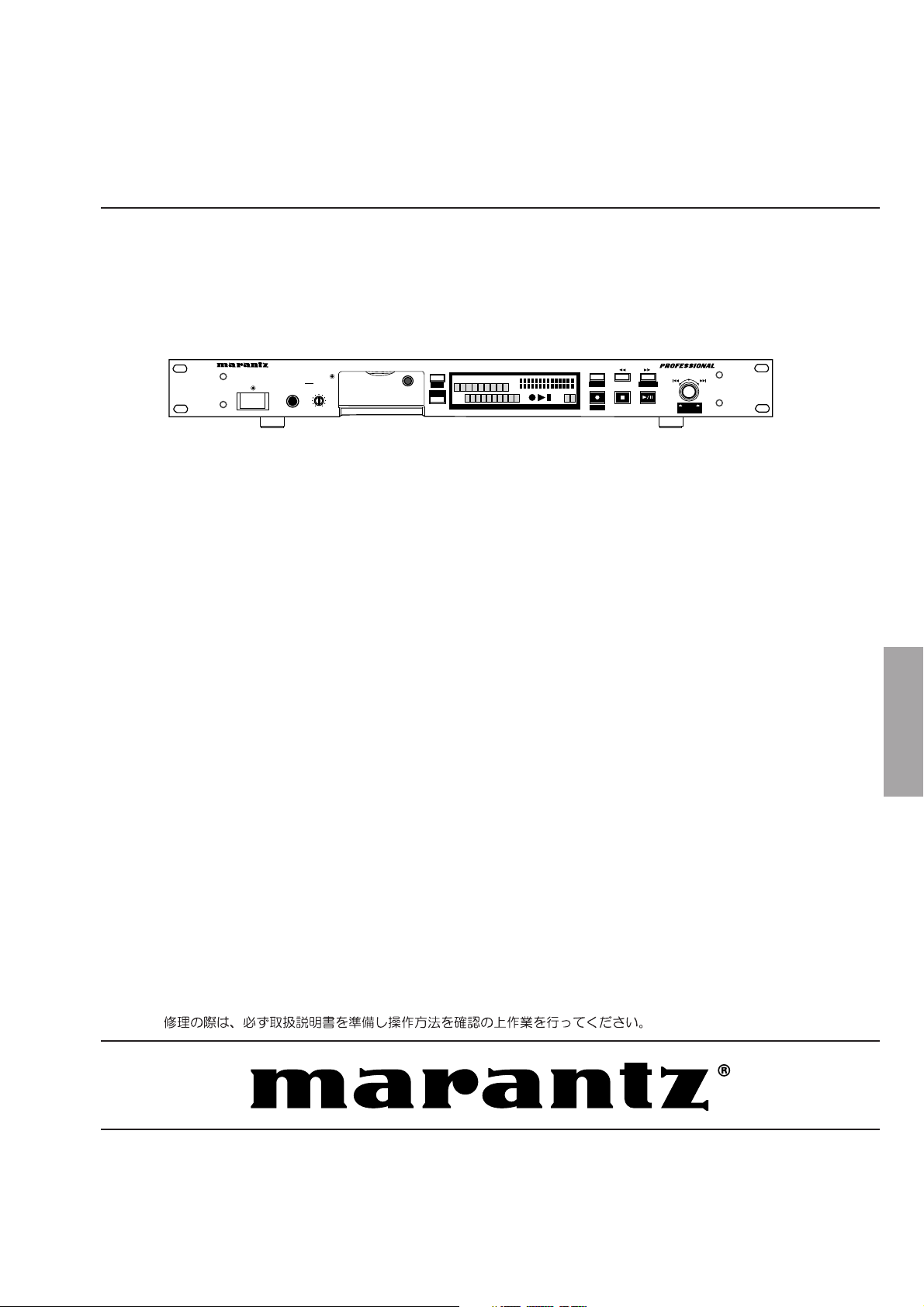
SOLID STATE RECORDER PMD570
HEADPHONE LEVELPOWER ON/OFF
SECTION PAGE
1. TECHNICAL SPECIFICATIONS ............................................................................................ 1
2. SERVICE MODE .................................................................................................................... 2
3. LCD CONTRAST ADJUSTMENT .......................................................................................... 3
4. MAIN MICROPROCESSOR (QU01) UPDATE PROCEDURE .............................................. 3
5. WIRING DIAGRAM .............................................................................................................. 19
6. BLOCK DIAGRAM ............................................................................................................... 21
7. SCHEMATIC DIAGRAM....................................................................................................... 23
8. PARTS LOCATION .............................................................................................................. 49
9. MICROPROCESSOR AND IC DATA ................................................................................... 55
10. EXPLODED VIEW AND PARTS LIST .................................................................................. 69
11. ELECTRICAL PARTS LIST .................................................................................................. 73
Solid State Recorder
DISPLAY
TOTALTRACKTIME
A-B
RECREMAIN kbps
LOCK
SHIFT
TRACK
0
10
MARK
L
00
20
40
-dB
kHz
R
AM
PM
LINE
TABLE OF CONTENTS
MENU/STORE
0261
over
2
EDIT
UNDO
-dB
S.SKIP
CANCEL
MARK
M. RESET
REC LEVEL/SELECT
MARK
REC BAL
ENTER
PUSH
PMD570
Please use this service manual with referring to the user guide (D.F.U) without fail.
PMD570
Part no. 49AS855010
First Issue 2004.04
ecm
Page 2
MARANTZ DESIGN AND SERVICE
Using superior design and selected high grade components, MARANTZ company has created the ultimate in stereo sound.
Only original
MARANTZ parts can insure that your MARANTZ product will continue to perform to the specifications for which
it is famous.
Parts for your
MARANTZ equipment are generally available to our National Marantz Subsidiary or Agent.
ORDERING PARTS :
Parts can be ordered either by mail or by Fax.. In both cases, the correct part number has to be specified.
The following information must be supplied to eliminate delays in processing your order :
1. Complete address
2. Complete part numbers and quantities required
3. Description of parts
4. Model number for which part is required
5. Way of shipment
6. Signature : any order form or Fax. must be signed, otherwise such part order will be considered as null and void.
USA
MARANTZ AMERICA, INC
1100 MAPLEWOOD DRIVE
ITASCA, IL. 60143
USA
PHONE : 630 - 741 - 0300
FAX : 630 - 741 - 0301
AMERICAS
SUPERSCOPE TECHNOLOGIES, INC.
MARANTZ PROFESSIONAL PRODUCTS
2640 WHITE OAK CIRCLE, SUITE A
AURORA, ILLINOIS 60504 USA
PHONE : 630 - 820 - 4800
FAX : 630 - 820 - 8103
AUSTRALIA
QualiFi Pty Ltd,
24 LIONEL ROAD,
MT. WAVERLEY VIC 3149
AUSTRALIA
PHONE : +61 - (0)3 - 9543 - 1522
FAX : +61 - (0)3 - 9543 - 3677
NEW ZEALAND
WILDASH AUDIO SYSTEMS NZ
14 MALVERN ROAD MT ALBERT
AUCKLAND NEW ZEALAND
PHONE : +64 - 9 - 8451958
FAX : +64 - 9 - 8463554
EUROPE / TRADING
MARANTZ EUROPE B.V.
P. O. BOX 8744, BUILDING SILVERPOINT
BEEMDSTRAAT 11, 5653 MA EINDHOVEN
THE NETHERLANDS
PHONE : +31 - 40 - 2507844
FAX : +31 - 40 - 2507860
AUSTRALIA
TECHNICAL AUDIO GROUP PTY, LTD
43-53 Bridge Rd.,
STANMORE NSW 2048
AUSTRALIA
PHONE : +61 - (0)2 - 9519 - 0900
FAX : +61 - (0)2 - 9519 - 0600
THAILAND
MRZ STANDARD CO., LTD
746 - 754 MAHACHAI ROAD.,
WANGBURAPAPIROM, PHRANAKORN,
BANGKOK, 10200 THAILAND
PHONE : +66 - 2 - 222 9181
FAX : +66 - 2 - 224 6795
TAIWAN
PAI- YUING CO., LTD.
6 TH FL NO, 148 SUNG KIANG ROAD,
TAIPEI, 10429, TAIWAN R.O.C.
PHONE : +886 - 2 - 25221304
FAX : +886 - 2 - 25630415
CANADA
MARANTZ CANADA INC.
5-505 APPLE CREEK BLVD.
MARKHAM, ONTARIO L3R 5B1
CANADA
PHONE : 905 - 415 - 9292
FAX : 905 - 475 - 4159
HONG KONG
Jolly ProAudio Broadcast Engineering Ltd.
UNIT 2, 10F, WAH HUNG CENTRE,
41 HUNG TO ROAD, KWUN TONG, KLN.,
HONG KONG
PHONE : 852 - 21913660
FAX : 852 - 21913990
SINGAPORE
WO KEE HONG DISTRIBUTION PTE LTD
No.1 JALAN KILANG TIMOR
#08-03 PACIFIC TECH CENTRE
SINGAPORE 159303
PHONE : +65 6376 0338
FAX : +65 6376 0166
MALAYSIA
WO KEE HONG ELECTRONICS SDN. BHD.
2ND FLOOR BANGUNAN INFINITE CENTRE
LOT 1, JALAN 13/6, 46200 PETALING JAYA
SELANGOR DARUL EHSAN, MALAYSIA
PHONE : +60 - 3 - 7954 8088
FAX : +60 - 3 - 7954 7088
JAPAN
MARANTZ JAPAN, INC.
35- 1, 7- CHOME, SAGAMIONO
SAGAMIHARA - SHI, KANAGAWA
JAPAN 228-8505
PHONE : +81 42 748 1013
FAX : +81 42 741 9190
Technical
KOREA
MK ENTERPRISES LTD.
ROOM 604/605, ELECTRO-OFFICETEL, 16-58,
3GA, HANGANG-RO, YONGSAN-KU, SEOUL
KOREA
PHONE : +822 - 3232 - 155
FAX : +822 - 3232 - 154
SHOCK, FIRE HAZARD SERVICE TEST :
CAUTION : After servicing this appliance and prior to returning to customer, measure the resistance between either primary AC
cord connector pins ( with unit NOT connected to AC mains and its Power switch ON ), and the face or Front Panel of product and
controls and chassis bottom.
Any resistance measurement less than 1 Megohms should cause unit to be repaired or corrected before AC power is applied, and
verified before it is return to the user/customer.
Ref. UL Standard No. 1492.
In case of difficulties, do not hesitate to contact the Technical
Department at above mentioned address.
040401ECM
Page 3

1. TECHNICAL SPECIFICATIONS
Digital audio system
System ................................................. Solid State Recorder
Usable Media ............................................ CF memory cards
(Microdrive) cards
Recording and media methods
.mp2 ................................. MPEG1 Layer II compression
.mp3 ................................ MPEG1 Layer III compression
.mp3 ............................... MPEG2 Layer III compression*
*for all half sample rates.
PCM ..................................................... 16 bit linear PCM
Recording bit rate (selectable)
MP2 mono ......................... 192, 128, 96, 64, 48, 32 kbps
MP2 stereo ...................... 384, 256,192,128, 96, 64 kbps
MP3 mono ......................... 160, 128, 80, 64, 40, 32 kbps
MP3 stereo ...................... 320, 256,160,128, 80, 64 kbps
Sampling frequency
Analog ........................ 48, 44.1, 32, 24*, 22.05*, 16* kHz
*except MP2
Digital .......................................................... 48, 44.1 kHz
Number of channels ...............................2 (stereo), 1 (mono)
Audio
Frequency response ............................... 20,000 Hz (-0.5dB)
Signal-to-Noise Ratio
IEC-A weighted ....................................................... 91 dB
Total Harmonic Distortion
at 0 VU (PCM) ....................................................... 0.01%
Dynamic Range............................................................ 94 dB
Inputs
BALANCED IN L/R
Type................................. XLR (1:GND, 2:HOT, 3:COLD)
Input Sensitivity ................................... +16dBu/@0dBFS
(+4dBu/@-12dBFS) / 24 kohms
Trim Control ...................................................... 0 to 24dB
LINE IN L/R
Type ................................................................. RCA jack
Input Sensitivity .......................... 500 mVrms/22 kohms
DIGITAL IN
Type...................................................................RCA jack
Input impedance ................................................. 75 ohms
Standard input level ............................................ 0.5 Vp-p
Sampling frequency ...................................... 44.1/48 kHz
Format ........................................ SPDIF (IEC 958 TypeII)
General
Power requirements
Japan model .........................................AC100V 50/60Hz
US model ................................................... AC120V 60Hz
European model ......................... AC100
Power consumption....................................................... 5.3W
Headphone Output power ........................... 20 mW/32 ohms
Dimensions
Width .................................................................. 483 mm
Height ................................................................... 52 mm
Depth .................................................................. 298 mm
Weight .................................................................... 3.0 kg
Included accessories
CF card* (64MB) ........................................................... 1
Power cord .................................................................... 1
I/O cable ........................................................................ 1
Stereo audio cables ....................................................... 2
Screw (ISO 3x10 mm) ................................................... 2
Plastic pin and retainer .................................................. 1
User Guide .................................................................... 1
* A CF card (Compact Flash™ memory card) or a
Microdrive™ is needed for the PMD570 to work. Also
used in digital cameras, removable flash memory media
are widely available at consumer electronics retailers and
computer resellers. Removable flash memory media
come in a variety of sizes and connection configurations.
The PMD570 accepts "Compact Flash" and "Microdrive"
media.
The recording time depends on the size of the CF card
and the recording parameters.
Optional Accessories
(See www.d-mpro.com for descriptions and/or ordering
information.)
Remote control
Model RC600 .............................................. wired remote
start recording, pause recording, add EDL marks
-
240V 50/60Hz
Outputs
LINE OUT L/R
Type................................................................... RCA jack
Standard level .............................2 Vrms max./300 ohms
DIGITAL OUT
Type................................................................... RCA jack
Output impedance .............................................. 75 ohms
Standard output level ......................................... 0.5 Vp-p
Sampling frequency ...................................... 44.1/48 kHz
Format .......................................SPDIF (IEC-958 Type II)
1
Page 4
2. SERVICE MODE
2.1. Micro Processor Version check
1. Keep inserting the CompactFlash, press the POWER but-
ton while pressing MENU/STORE and REC button.
(MENU/STORE and REC button are pushed 3 seconds or
more.)
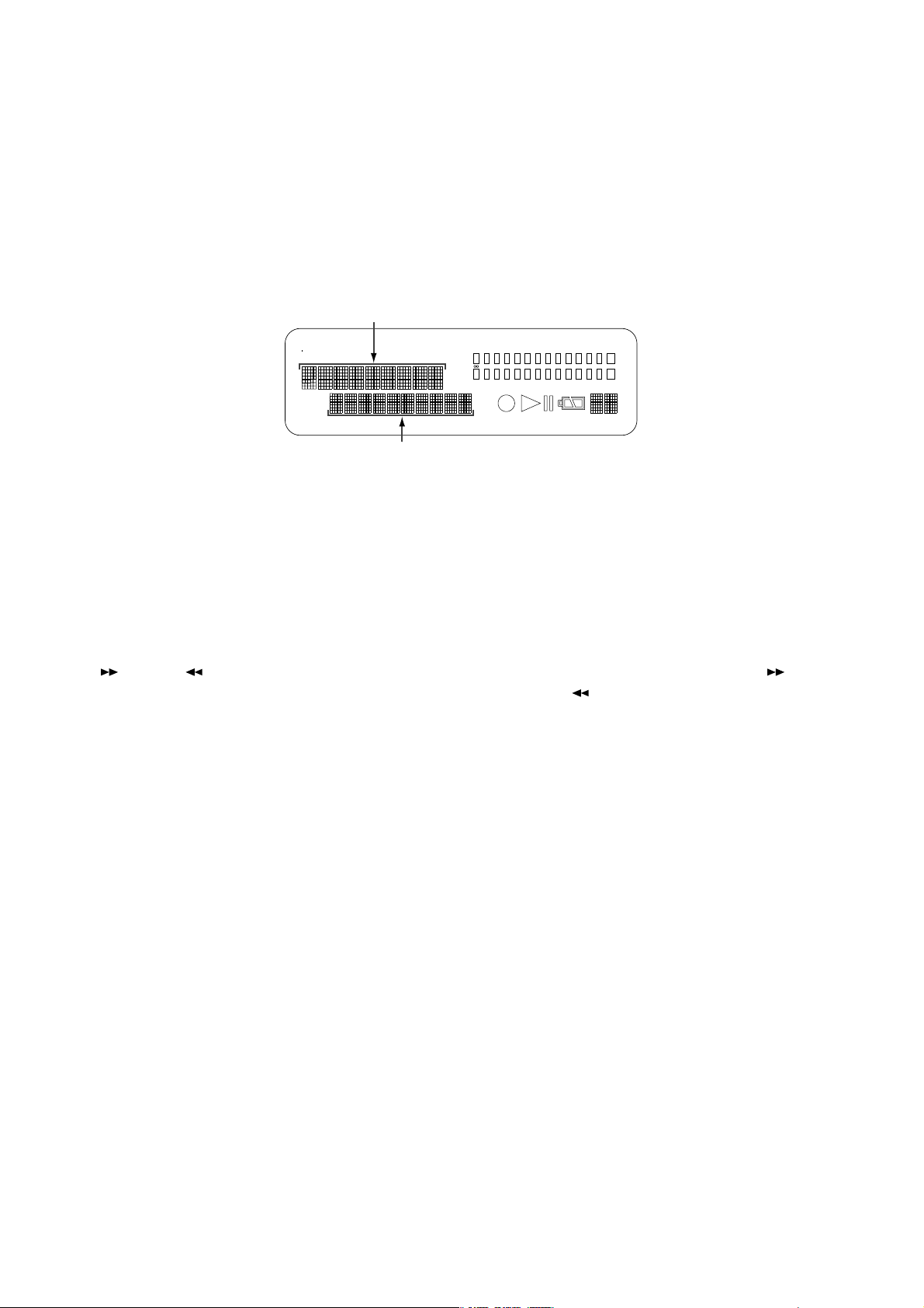
2. VERSION name is displayed on LCD with blink, then press
PLAY/PAUSE button, VERSION is displayed on LCD.
Example : DSP 01.20
MPU B0022
DSP XX.XX
2.SERVICEモード
2.1.VERSION 確認
1. CompactFlashが挿入されている状態で、MENU/STORE
ボタンとREC ボタンを押しながら POWERボタンを押し
ます。(3秒以上MENU/STOREボタンと REC ボタンを押
します。)
2. DISPLAYにVERSIONと点滅表示されたらPLAY/PAUSE
ボタンを押してバージョンを確認します。
表示例: DSP01.20
MPUB0022
TOTAL
RE
TRACK
M
A
RK
REMAIN
C
TRACK
kbps
TIME
A-B
L
-
40 20 12 6 2 0
dB
kHz
R
M
A
PM
INT
MIC
LINE
S.SKIP
OVER
-
dB
MPU XX.XX
3. Turn off power to quit Service mode. 3. SERVICE モード解除は、電源を切ります。
2.2. CompactFlash read/write speed check
1. Insert the CompactFlash, Press the POWER button while
pressing MENU/STORE and REC button. (MENU/STORE
and REC button are pushed 3 seconds or more.)
2. VERSION name is displayed on LCD with blink, then press
(FWD) or (REW) button. CARD CHECK name is
displayed on LCD.
3. Then press PLAY/PAUSE button. CARD CHECK name is
displayed on LCD. after Good or No Good is displayed on
LCD.
If “No good” is displayed, the CompactFlash is not correct.
Insert the correct CompactFlash.
Because read/write speed is slow, the unit has the possi-
bility that sound is interrupted and stop during recording.
4. Turn off power to quit Service mode.
2.2.CompactFlash 書換え速度確認
1. CompactFlashが挿入されている状態で、MENU/STORE
ボタンとREC ボタンを押しながら POWERボタンを押し
ます。(3 秒以上 MENU/STORE ボタンと REC ボタンを押
します。)
2. DISPLAYにVERSIONと点滅表示されたら、 (FWD)ボ
タンまたは (REW)ボタンを押すと、DISPLAY に
CARDCHECK と表示されます。
3. さらに、PLAY/PAUSE ボタンを押すと、DISPLAY に
Checkspeedと表示されたのち、GoodまたはNoGoodが
表示されます。
NoGood の場合:書き換え速度が遅い為、録音途中で止
まる、または音切れが発生する可能性があります。
CompactFlash を別の物に交換して下さい。
4. SERVICE モード解除は、電源を切ります。
2
Page 5
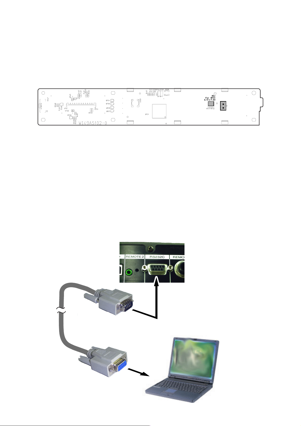
3. LCD CONTRAST ADJUSTMENT
1. Connect the TEST POINT (See below) with the tester.
2. Turn the variable resistor RF01 so that the reading of the
tester becomes 7.0 V ± 0.1 V and conferm the contrast of
the LCD becames maximum.
PF01 FRONT LCD
3.LCD輝度電圧調整
LCDモジュールとメイン基板(PF01)をペアーとして以下の調
整をおこなってください。
1.TESTPOINTJF02にテスターを接続し、輝度電圧を測
りながらボリューム RF01 の抵抗値を調整します。
2.LCDを正面から見て、コントラストが最大になることを確
認しながら輝度電圧を 7.0V±0.1V に調整します。
4. MAIN MICROPROCESSOR (QU01)
UPDATE PROCEDURE
Necessary Equipment
• Windows PC (Windows2000 or WindowsXP) with COM
port
• RS232C cable straight type (9pin female
• Update Disc (*PMD570CDR)
4.1. Connection
1. Connect COM port of Windows PC and PMD570 with
RS232C cable.
-
9Pin male )
RF01
JF02
TEST POINT
4. Mainmicroprocessor(QU01)
アップデート方法
必要機器
・ WindowsPC(OS:Windows2000または WindowsXP)
で COMport のあるもの
・ RS232C ストレートケーブル(9pin メス-9pin オス)
・ マイコンアップデートディスク(*PMD570CDR)
4.1.接続方法
1 PMD570とWindowsPCのCOMポートをRS232Cケー
ブルで接続します。
RC232C cable
PMD570 Rear Panel
RS232C Terminal
Windows PC
COM Port
3
Page 6
4.2. Installs of The software
(Flash Development Toolkit 3.0)
4.2.書き込みソフトウェアのインストール
(FlashDevelopmentToolkit3.0)
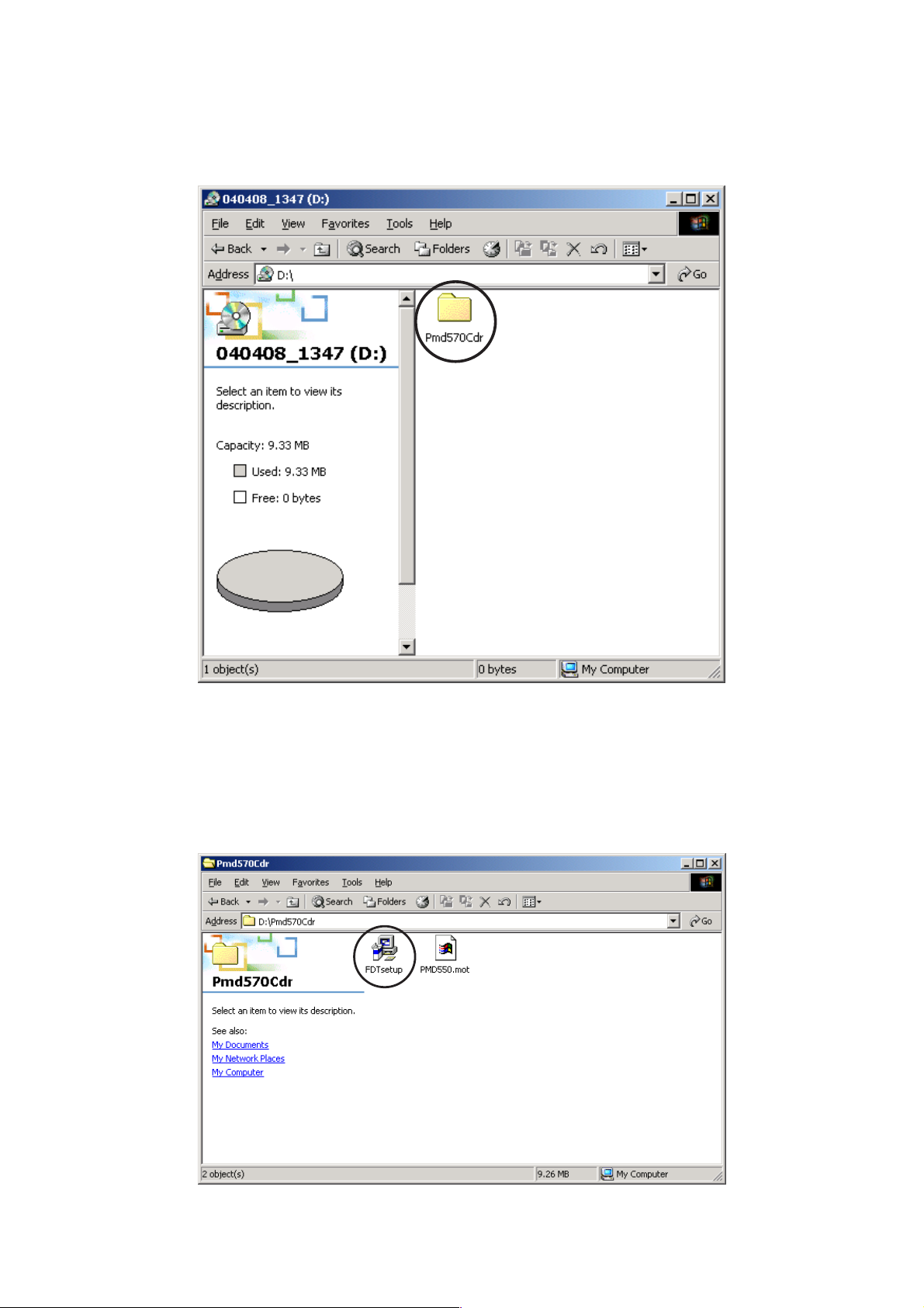
1. Open the CD-ROM (*PMD570CDR) Disc, and double click
soft folder.
1. CD-ROM(*PMD570CDR)のsoft フォルダをダブルク
リックします。
2. Double click the FDT setup.exe 2. FDTsetup.exe をダブルクリックします。
4
Page 7
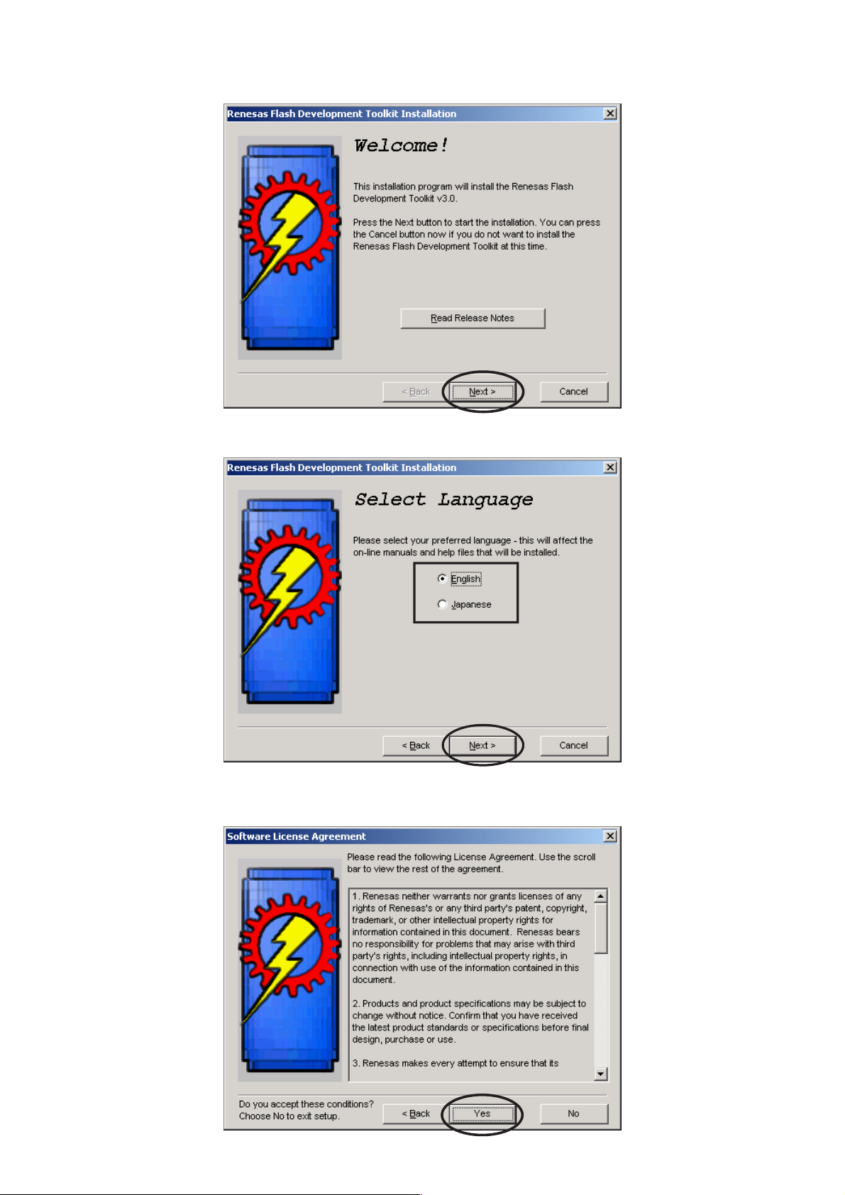
3. Click Next. 3. インストールウィザードが起動します。
Next をクリックします。
4. Choose the language. And click Next.
5. Click Yes .
4. 言語を選んで Next をクリックします。
5. Yes をクリックします。
5
Page 8
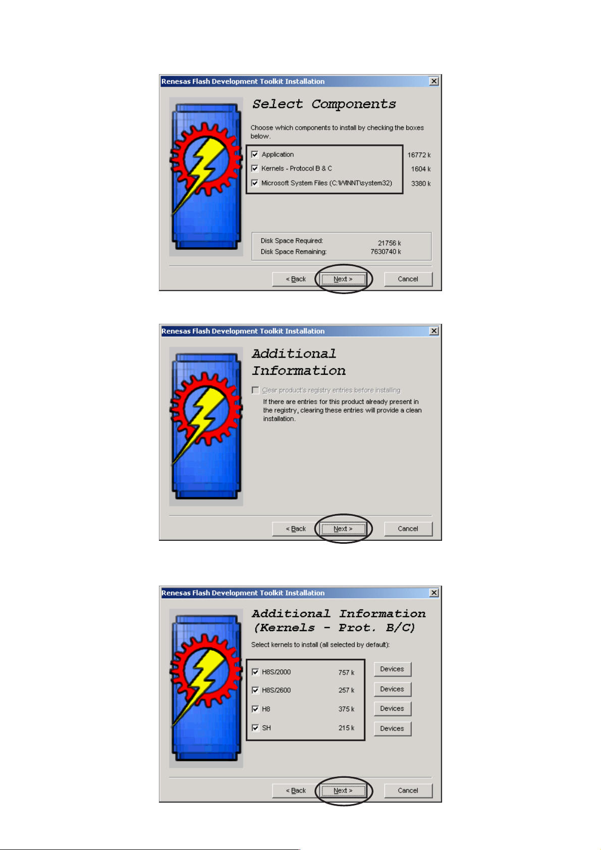
6. Check to the all check boxes. And click Next.
6. チェックボックス全てにチェックが入っていることを確
認して Next をクリックします。
7. Click Next.
8. Check to the all check boxes. And click Next.
7. Next をクリックします。
8. チェックボックス全てにチェックが入っていることを確
認して Next をクリックします。
6
Page 9

9. Click Next.
9. Next をクリックします。
10. Click Next.
11. Click Next.
10.Next をクリックします。
11.Next をクリックします。
7
Page 10
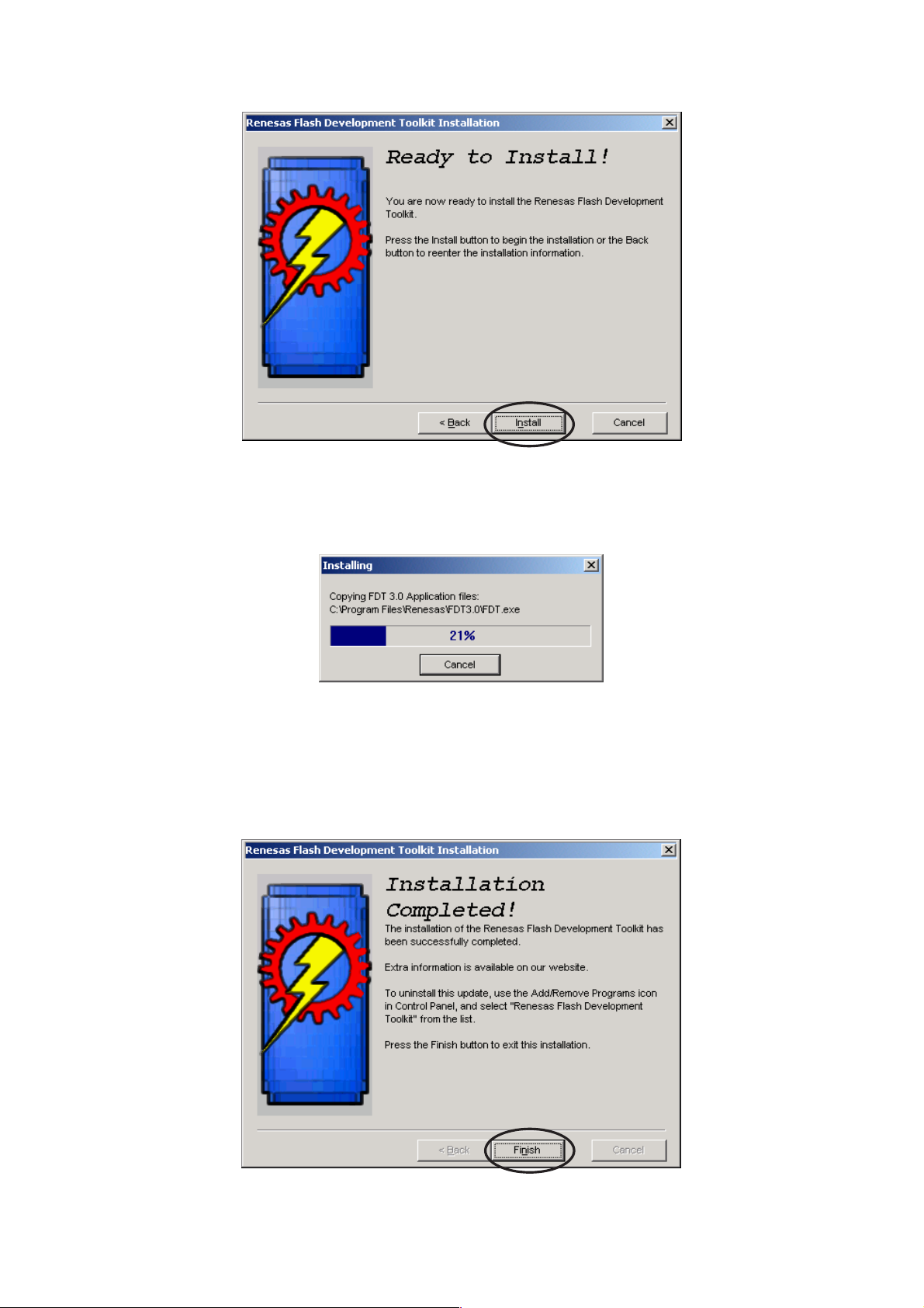
12. Click Install.
12.Install をクリックします。
13. The status bar appears.
14. Click Finish.
13.インストールを開始します。
14.Finishをクリックして書き込みソフトウェアのインストー
ルを完了します。
8
Page 11
4.3. The writing software setup procedure.
4.3.書き込みソフトウェアの設定
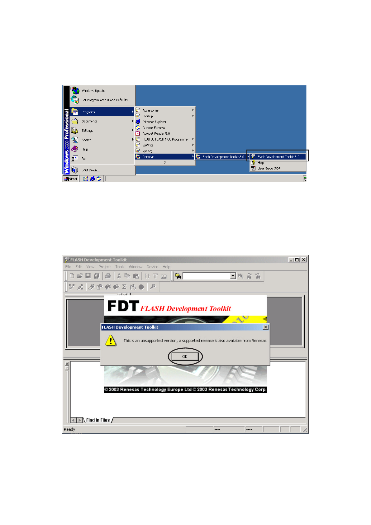
Launch up the writing software.
1. Click Start / Programs / Renesas / Flash Development
Toolkit 3.0 / Flash Development Toolkit 3.0.
ソフトウェアの起動
1. Start/Programs/Renesas/FlashDevelopmentToolkit
3.0/FlashDevelopmentToolkit3.0
をクリックします。
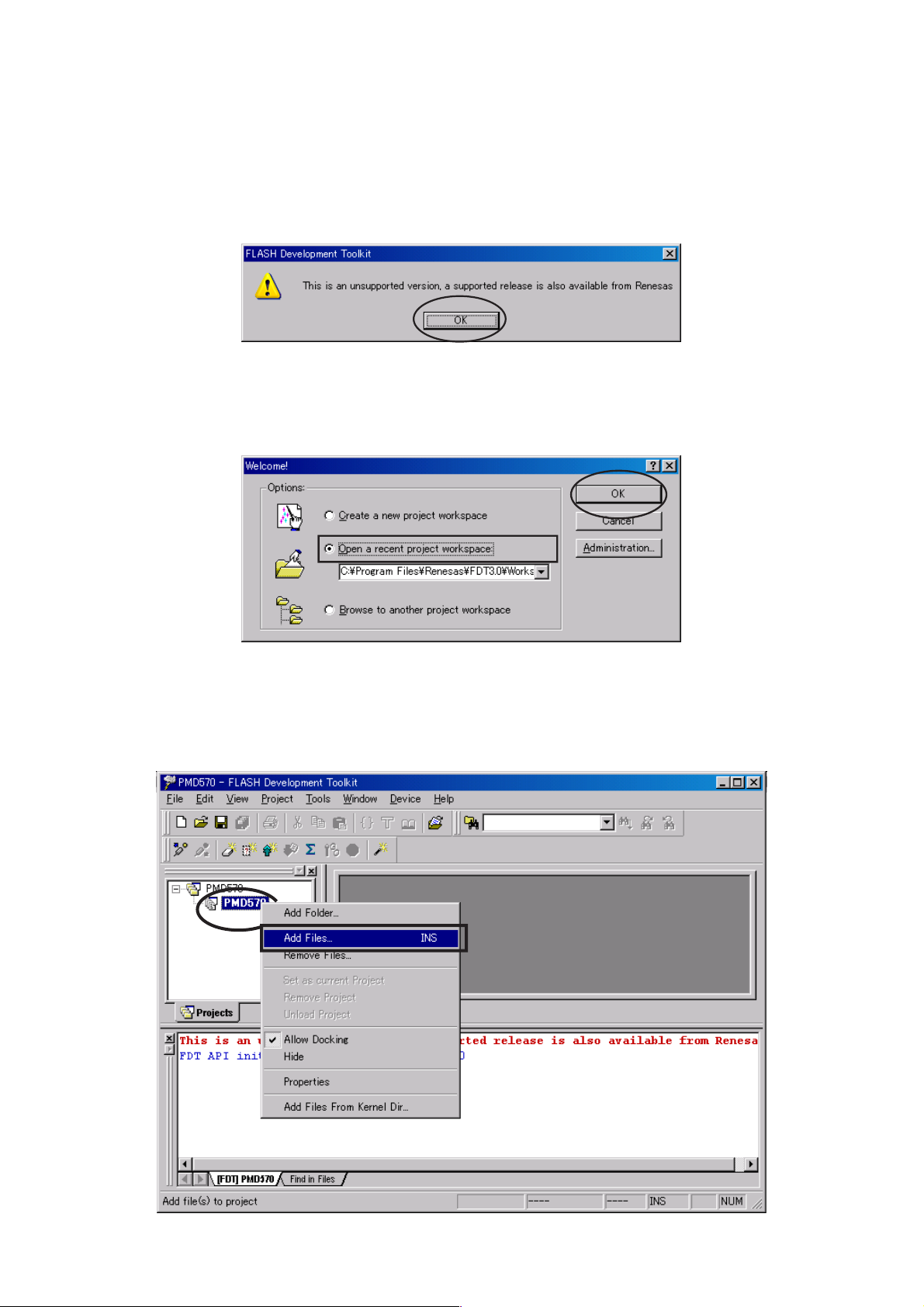
2. Click OK. (This window appears at every starting.)
2. OKをクリックします。(起動のたびに下記のコマンドが出
ますのでその都度 OK をクリックしてください。)
9
Page 12
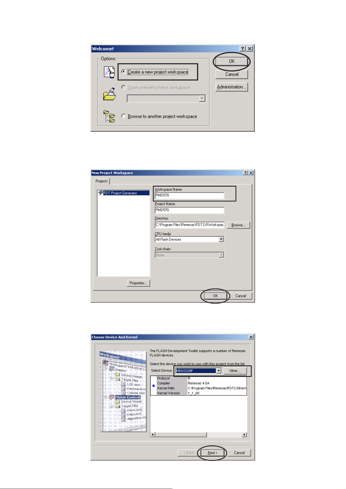
3. Check Create a new project workspace, and click OK.
3. Createanewprojectworkspace にチェックを入れ、OK
をクリックします。
4. PMD570 is inputted into the Workspace name.
(It is simultaneously inputted into Project Name.)
Click OK.
4. WorkspaceName に PMD570 と入力します。
(同時に ProjectName にも入力されます。)
OK をクリックします。
5. Choose the H8S/2328F in Select Device.
Click Next.
5. SelectDevice から H8S/2328F を選び、クリックします。
Next をクリックします。
10
Page 13
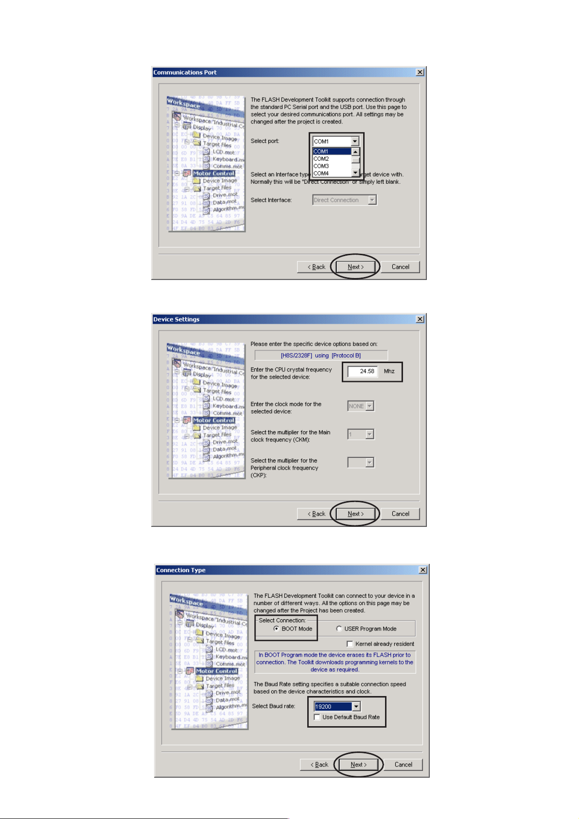
6. Choose the Serial port No. in the Select Port.
Click Next.
6. SelectPort から接続する SerialPort 番号を選び、クリッ
クします。Next をクリックします。
7. 24.58 is inputted into the "Enter the CPU crystal frequency
for the selected device:". Click Next.
8. Check the BOOT Mode in Select Connection.
Choose the 19200 in Select Baud rate. Click Next.
7. "EntertheCPUcrystalfrequencyfortheselected
device:" に 24.58 と入力します。Next をクリックします。
8. SelectConnection:からBOOTModeにチェックを入れます。
SelectBaudrate:から19200を選び、Nextをクリックします。
Remark:
Please remove check
mark, if it is contained
in Use Default Baud
Rate.
注意
UseDefaultBaudRate
にチェックが入ってい
ると BaudRate を変更
できませんのでチェッ
クを外してください。
11
Page 14
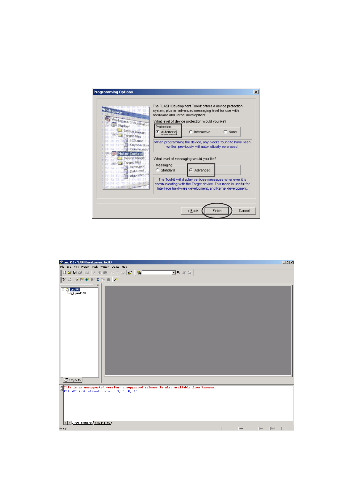
9. Check the Automatic in Protection.
Check the Advanced in Messaging.
Click Finish.
9. Protection から Automatic にチェックを入れます。
Messaging から Advanced にチェックを入れます。
Finish をクリックします。
以上で設定は完了です。
12
Page 15
4.4. Writing procedure
1. Click Start/Programs/Renesas/Flash Development
Toolkit3.0/Flash Development Toolkit3.0.
4.4. 書き込み方法
1. Start /Programs /Renesas/FlashDevelopment
Toolkit3.0/FlashDevelopmentToolkit3.0
をクリックします。
2. Click OK. (This window appears at every starting)
3. Check Open a recent project workspace, and click OK.
2. OK をクリックします。(起動のたびに下記のコマンドが
出ますのでその都度 OK をクリックしてください)
3. Openarecentprojectworkspaceをにチェックを入れて
OK をクリックします。
4. The right click PMD570, and Click Add Files....
4. 以下の画面が出ましたら、2階層目にあるPMD570のア
イコン上で右クリックをして、AddFiles をクリックし
ます。
13
Page 16
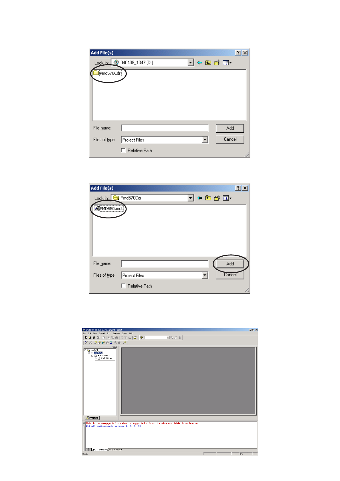
5. Open the CD-ROM (*PMD570CDR Disc) and double click
soft folder.
5. アップデートディスク(*PMD570CDR)の soft フォル
ダをダブルクリックします。
6. Select PMD550.mot, and Click Add.
7. The holder of PMD550.mot is made.
6. PMD550.mot を選択し、Add をクリックします。
7. PMD550.mot のホルダーが出来ます。
14
Page 17
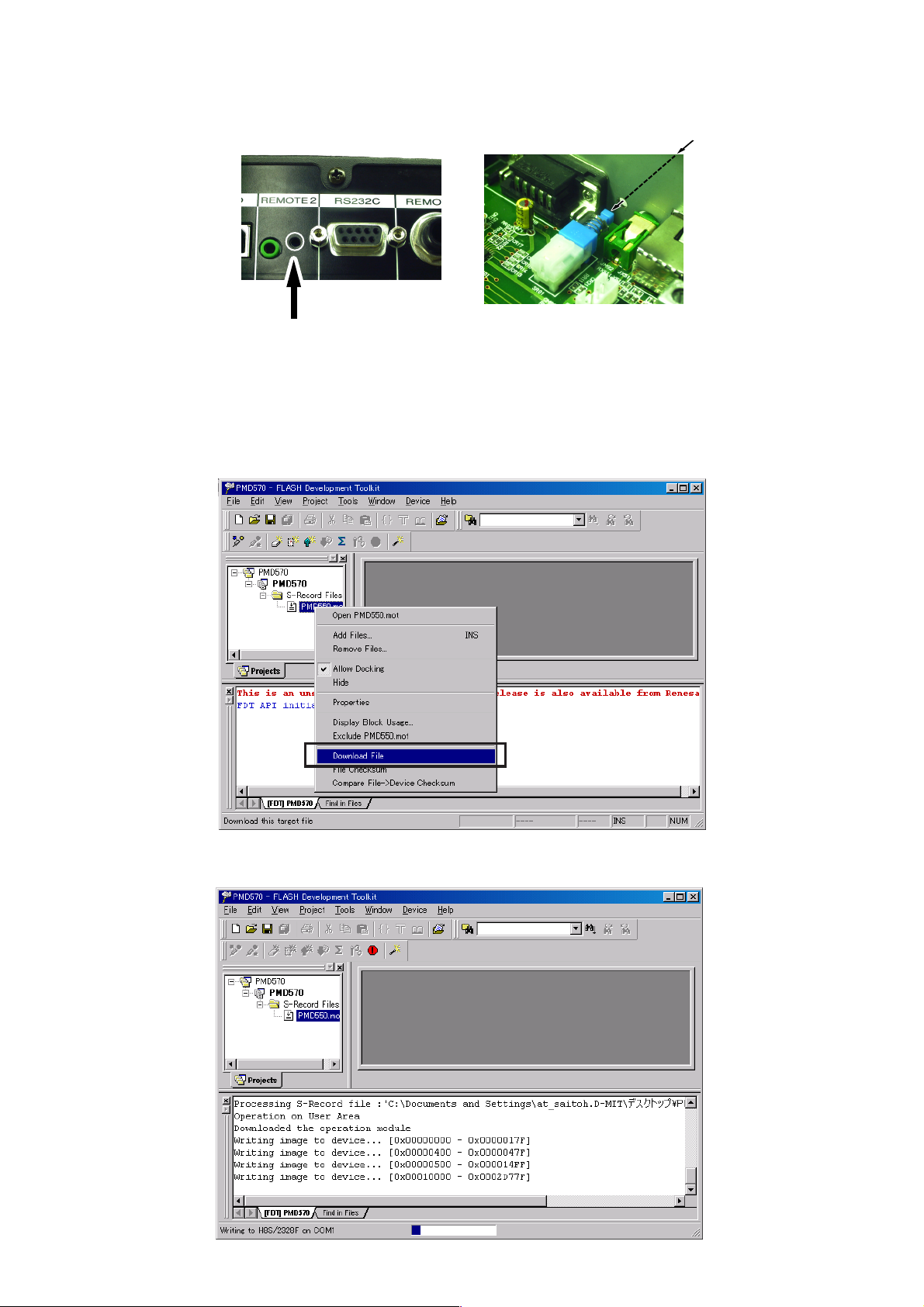
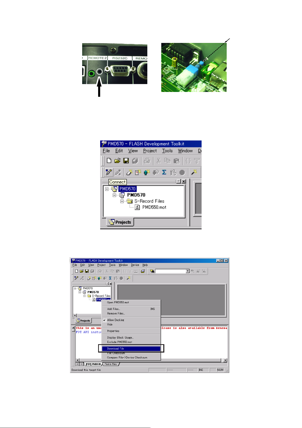
8. It checks that PMD570 and the COM port are connected
by RS232C cable.
9. Insert a thin rot to the hole and push the switch inside to
turn on the switch.
PMD570 Rear Panel PMD570 Inside
8. PMD570 とWindowsPC のCOM ポートの接続を確認し
ます。
9. リアパネルのREMOTE2端子の横にある内部スイッチを
ON します。
Push
Push
10. Press POWER Button to turn on the unit.
The unit is in the boot mode.( LED and LCD display on the
front panel disappear.)
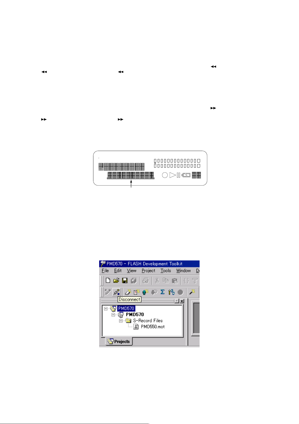
11. The right click PMD550.mot, and Click Download File.
Switch
10.POWERボタンを押し、PowerOn 状態にします。
(この状態より、書き込みモードですが、前面の LED 及び
LCD 表示は消えます。)
11.4階層目にあるPMD550.motのアイコン上で右クリック
をしてDownloadFileをクリックします。
12. The screen becomes the uploading condition.
When writing is finished, the below message appears on the screen.
12.
書き込みが始まると下のような画面が出て状態を表示します。
書き込みが終わると下のような画面が出ます。
15
Page 18
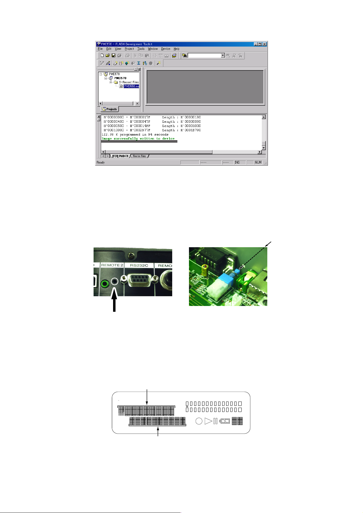
13. The Main microprocessor (QU01) has been Update.
13.以上で、書き込み作業は終了です。
14. Turn off the internal switch that has been turned on at
step 9.
NOTICE:
When the internal switch is not turned off, the set becomes
the mode of update of firmware every time to turn on the unit.
14.リアパネルのREMOTE2端子の横にある内部スイッチを
OFF します。
注意
この操作をしないと PMD570 の電源を入れた時、毎回書き
込みモードになります。
Push
PMD570 Rear Panel PMD570 Inside
Push
15. Turn off Power switch, then disconnect RS232C cable from
15.PMD570 の電源を切り、RS232C ケーブルを外します。
Switch
PMD570.
16.VERSION の確認をします。
16. Check the version number of the firmware
Refer to 2-page ”2. SERVICE MODE“ for “2.1. Micro-Pro-
cessor Version check“ confirmation.
2 ページ2.SERVICE モードの 2.1.VERSION 確認で
確認します。
書き込んだ、バージョンが正しければ書き換え完了です。
TOTAL
RE
TRACK
A
RK
M
REMAIN
C
TRACK
DSP XX.XX
A-B
TIME
kbps
MPU XX.XX
L
-
40 20 12 6 2 0
dB
kHz
R
M
A
PM
INT
MIC
LINE
S.SKIP
OVER
-
dB
16
Page 19
4.5. FACTORY MODE
4.5.FACTORYモード
After the completion of update of Main microprocessor (QU01),
to reset all setting to default status, follow the procedure below.
/N version
1. Press the POWER button while pressing MENU/STORE
and (REW) button. (MENU/STORE and (REW) but-
ton are pushed 3 seconds or more.)
2. FACTORY name is displayed on LCD. The unit becomes
the setup of default automatically.
/F and /U version
1. Press the POWER button while pressing MENU/STORE
and (FWD) button. (MENU/STORE and (FWD) but-
ton are pushed 3 seconds or more.)
2. FACTORY name is displayed on LCD. The unit becomes
the setup of default automatically.
TOTAL
RE
TRACK
A
RK
M
REMAIN
C
TRACK
kbps
TIME
A-B
kHz
A
PM
ソフトのバージョンアップをした際には、仕向け別に出荷設
定(EEPROM の初期化)を行ないます。
/N 仕向け
1. MENU/STORE ボタンと
POWER ボタンを押します。3 秒以上ボタンを押します。
2. FACTORY と表示がでます。自動的に出荷時の設定にな
ります。
(REW)
ボタンを押しながら
/F と /U 仕向け
1. MENU/STORE ボタンと (FWD)ボタンを押しながら
POWER ボタンを押します。3 秒以上ボタンを押します。
2. FACTORY と表示がでます。自動的に出荷時の設定にな
ります。
L
-
40 20 12 6 2 0
dB
R
M
INT
MIC
LINE
S.SKIP
OVER
-
dB
Factory
処理中は、Factory と表示されます。完了したら、通常表示となります。
Displayed as “Factory” during processing. And display returns after complete.
4.6. The procedure of upload firmware two or more Units continuously
1. Click Disconnect.
4.6.書き込みを複数台連続で行なうときは ...
1.
Disconnectをクリックして、未接続状態にします
2. Replace the unit with a new one and connect RS-232C
cable to the set.
2.
新しいセットに入れ替え、WindowsPC とケーブルにて
接続します。
17
Page 20
3. Insert a thin rot to the hole and push the switch inside to
turn on the switch.
PMD570 Rear Panel PMD570 Inside
3. リアパネルのREMOTE2端子の横にある内部スイッチを
ON します。
Push
Push
4. Press POWER Button to turn on the unit.
The unit is in the boot mode.( LED and LCD display on the
front panel disappear.)
5. Click Connect.
Switch
4. POWERボタンを押し、PowerOn 状態にします。
(この状態より、書き込みモードですが、前面の LED 及び
LCD 表示は消えます。)
5.
Connectをクリックして、接続状態にします
6. The right click PMD570, and Click Download File.
6. 4階層目にあるPMD550.motのアイコン上で右クリック
をしてDownloadFileをクリックします。
7. After this procedure, continues to step 12.
7.
以降は4.4.書き込み方法の手順12から引き続いてを行な
います。
18
Page 21
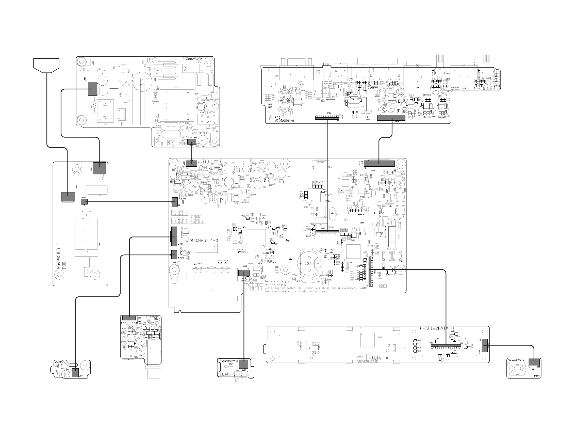
J951
J991
J992
J852
J851
J971
J351
JU09
JU10
JU81
JF01
JF03
JS01
JU08
JU06
J352
JA03
JM94
JC01
JF91
J993
PF01 FRONT LED
PU81
ACCESS LED/
DETECTOR
PC01
H/P VOL.
PF91 POWER LED
P901
POWER
P951 SUPPLY
AC INLET
PA01
REAR I / O
PM01
MAIN
PS01 JOG
5. WIRING DIAGRAM
19 20
Page 22
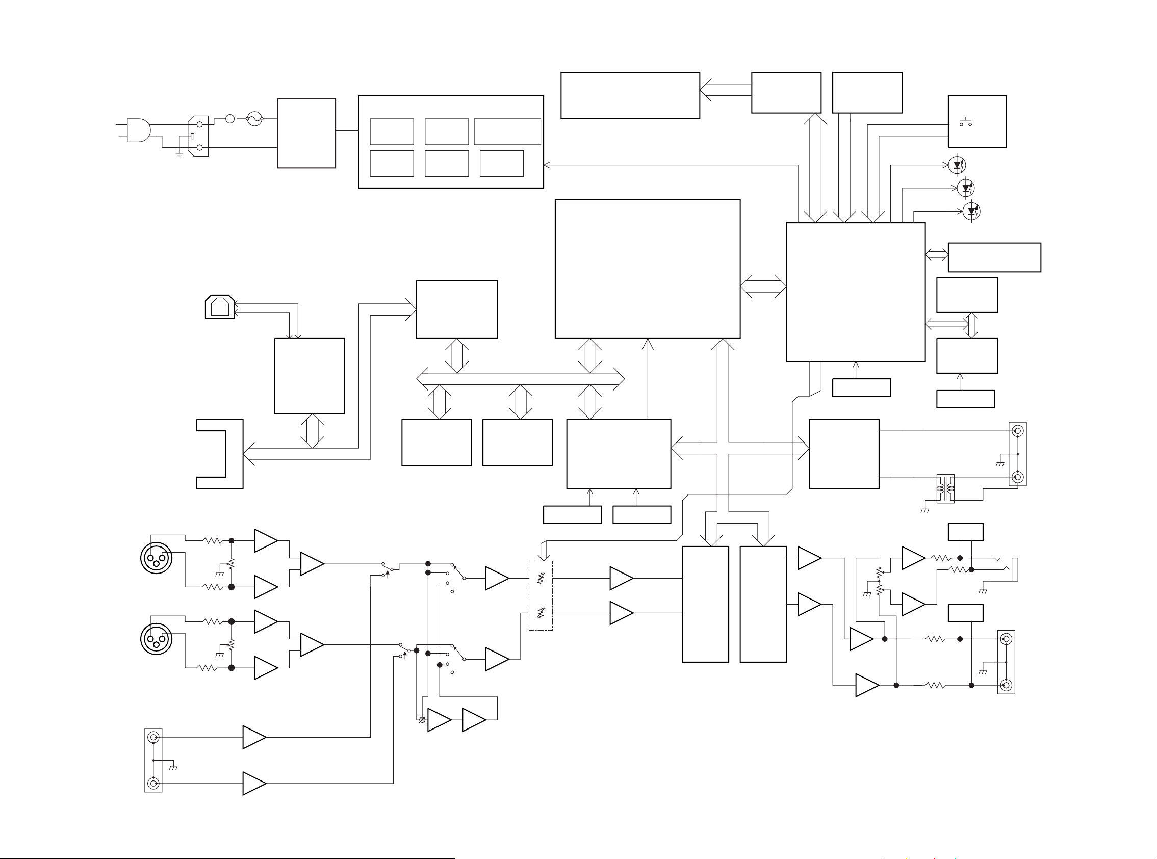
6. BLOCK DIAGRAM
1.6A
1
2
3
EARTH
DC-DC POWER SUPPLY
+3.3V
FOR up
FOR DSP
+1.6V
+3.3V
FOR DSP
+5V +-9V
LCD DISPLAY
VF01
NJU6469
LCD DRIVER
QF01
KEY SW
FRONT uP
H8S/2328F
QU01
24.576MHz
TIMMER
RS5C372A
EEPROM
AT24C01A
REC LED
STANDBY LED
DSP
TMS320VC5416-160
QD01
CPLD
XC9536XL-VQ64-10C
DIT/DIR
AK4114
Q401
QP01
SRAM
4Mbitx2
Cycle Time:80ns
QD03,QD04
Flash ROM
8Mbitx1
QD02
Cycle Time:90ns
BUS BUFFER
QX03
QX04
QX05
USB DRIVER
GL641USB
QX01
COMPACT FLASH
MICRODRIVE
USB CONNECTOR
ADC
AK5380
Q402
AK5380
Q402
ADC
MUTE
MUTE
LINE IN (XLR)
11.2896MHz 12.288MHz
32.768kHz
AC/DC
Converter
H/P OUT
DIGITAL IN
DIGITAL OUT
H/P VR
FRONT uP
HD0:HD7
CODEC DACONT
CODEC BCLK
CODEC WS
CODEC ADIN
CODEC MCLK
0dBu〜+24dBu
0dBu〜+24dBu
Input Sense VOL
EL POT
RS232C
DC 12.0v
ANALOG INPUT
SELECT
JOG
CLK112896MHzBUS I/F
Input Sense VOL
LINE IN
+5V +3.3v
FOR LCD LED
N
R
2221
Page 23

7. SCHEMATIC DIAGRAM
PM01-1/9
MAIN PCB
Q401
AK4114
DIT/DIR
ADC DAC
LRCK
MCKO2
DIF
BCIK
BICK
TTL
MCLK
VREF
SDTO
SCL
XTO
VDD
AVDD
XTI
LRCK
VSS
AK5380(ADC)
MCKO0
P/S
SDA
AK4380(DAC)
AOUTR
VCOM
LRCK
AVSS
AOUTL
VIN
TSTAINR
DAUX
AVSS
TVDD
VCOM
DGND
AINL
AVSS
SMUTE/CSN
TX1
PDN
AVSS
VD
MCLK
TX0
DFS/CCLK
XCTL0
INT1
AVSS
VA
DVSS
RX0
SCLK
XCTL1
INT0
SDTO DIFO/CDTI
DVDD
AVSS
AVSS
PDN
PDN
AGND
SDTI
VCOM
NC
DZF
INTERFACE FOR DSP
INTERFACE FOR CPLD
INTERFACE FOR CPU
INTERFACE FOR EXPANDER
L ch
R ch
Digital
2.5
2.5
2.5
5.0
3.2
1.2
1.6
1.7
1.6
3.3
0
2.5
2.5
2.5
5.0
-7.2
6.8
3.2
3.2
3.2
3.2
DM:Dummy
4.96v
3.23v
5.23v
AK5380
ANALOG_OUT_L
TO PM01 9/9
GND
GND
GND
GND
+5VA
NJM2068V
GND
ANALOG_OUT_R
NJM2068V
GND
AK4380
+5VA
GND
+5VD
GND
-9V
ANALOG_L
ANALOG_R
GND
GND
GND
GND
GND
GND
+9V
GND
GND
GND
GND
GND
+3VD
GND
GND
+3VD
GND
GND
CODEC_ADIN
CODEC_WS
CODEC_BCLK
CODEC_DACOUT
CODEC_WS
CODEC_MCLK
CODEC_BCLK
PDN
CS
DAI_IN
DAI_MCKO
DAI_MCLK
DAI_INT0
DAI_INT1
XCTL0
XCTL1
VIN
+3VD
GND
SDA
SCL
+3VD
+3VD
GND
GND
GND
GND
DIG_IN
DIG_OUT
DM
DM
+3VD
GND
DVSW
22k
10/16V
10/16V
10/10V
10/16V
0
100n
100k
10/16V
100n
47p 100
39k 47p
100n
10/16V
100n
0
100n
10/10V
10
100n
10k
0
10/16V 100n
10/10V
100k
100k
10/16V
10/16V
0
39k
47p
47p
100
100k
22k
10/16V
100n
10/10V
100n
BLM11B601
10/10V
100n
18k%
470n
DM
1u
10k
10k
10k
0
10k
100
10k
1k
BLM11B601
BLM11B601
BLM11B601
BLM11B601
BLM11B601
0
10
161514
13
1211109
87654321
1
2
3
4
7
6
5
8
161514131211109
87654321
13 14 15 16 17 18 19 20 21 22 23 24
12
11
10
9
8
7
6
5
4
3
2
1
48 47 46 45 44 43 42 41 40 39 38 37
36
35
34
33
32
31
30
29
28
27
26
25
2
3
1
2
3
1
R409
Q402
C425
C422
C420
C421
Q405
Q405
R406
Q403
C401
R417
C408
C406
C403 R405
R401 C405
C418
C423
C419
R412
C417
C429
R434
C409
R415
R414
C431 C412
C428
R410
R407
C426
C407
R411
R402
C402
C404
R408
R418
R404
C430 C415
C427
C410
TP42
TP41
L404
C424
C414
R425
C416
C411
C413
R428
R429
R430
R422
R427
R435
R437
R438
R433
R413
R432
R436
R403
Q421
Q422
R421
R416
CODEC_ADIN
PDN
CODEC_DACOUT
CS
VIN
XCTL1
XCTL0
CODEC_WS
CODEC_BCLK
CODEC_DACOUT
CODEC_ADIN
CODEC_WS
CODEC_BCLK
CODEC_DACOUT
DAI_IN
CODEC_WS
CODEC_MCLK
CODEC_BCLK
DAI_MCKO
DAI_MCLK
CS
PDN
DAI_INT0
DAI_INT1
XCTL0
XCTL1
VIN
SDA
SCL
SDA
SCL
DAI_INT1
DAI_MCLK
DAI_MCKO
PDN
DAI_INT0
CODEC_WS
CODEC_MCLK
CODEC_BCLK
DAI_IN
23 24
Page 24

QU01
64F3048BVF25
FRONT uP
TO PA01 JM94
N.C.
TO PF01 JF01
TO PF91 JF91
C
B
E
C
B
E
C
B
E
C
B
E
C
B
E
AUP
PCB SYM PM01
4LAYER
3.3
CTS
TXD
RTS
RXD
SCK
RXD
TXD
COVER DECECTOR
ACCESS LED
REMOTE
CTS
RTS
RXD
TXD
USB_IN
PU81
ACCESS LED
/DETECTOR PCB
PM01-2/9
MAIN PCB
ZU01
CR2032 (SANYO)
WA08
WA13
WA14
WA07
/INTRB
SCL
SDA
VSS
VDD
OSCIN
OSC OUT
/INTRA
4.49v
WRITE=1.95v
3.23v
GND
+3VU
GND
GND
GND
+3VU
GND
+3VU
GND
GND
GND
AT24C04N
GND
GND
+3VD
RS5C372A
GND
1SS301
+5VD
+3VD
GND
+3VU
GND
+3VU
AVSW
DVSW
HP_MUTE
LINE_MUTE
HBIL
HDS1Z
HRDY
HR/WZ
HCSZ
(L+R)/2
ST_MONO
HCNTL0
DSP_RSTZ
SDA
SCL
HD6
HD5
HCNTL1
HD4
HD0
HD3
HD1
HD2
HD7
CS
PDN
DAI_INT0
DAI_INT1
DSP_INT0
+3VD
GND
GND
CF_INSZ
GNDGNDGND
1SS301
CM200S
32.768kHz
GND
GND
+3VU
USB_SW
CF_BUS_ENB
XCTL0
XCTL1
VIN
DSP_INT0
GND GND
GND
GND
GND
+3VU
GND
+3VU
+3VU
GND
GND
GND
DB_STB
DB_CK
DB_DATA
BAL_UNBAL
DTC144EU
GND
POWER_IN
+3VU
+3VU
+3VU
GND
GND
+3VU
+3VD
GND
DIG_IN
DIG_OUT
U1
-D
+D
+3VU
GND
GND
DTC114EU
+3VU
2SA1576
2SC4116
GNDGNDGND
+B
+B
GND
GREEN
A1576
GND
+3VU
GND
ACCESS
1SS301
2SC4116
GNDGND
+5VH
+3.3VH
DSP_SW
+5VH
+3VU
+3VU
+3VU
+3VU
+3VU
2.4V
+3VU+3VU
DTC114EU
GND
DTA114EU
+3VU
+3VU+3VU
+3VU
2SC4116
GND
ACCESS2
STANDBY_SUPPLY
DTC114EU
DTC114EU
GND
GND
+3VD
+3VD
+3VU
GND
1SS301
DTC114EU
1SS301
1SS301
+3VD
GND
+3VU
GND
POWER_SW
+5VD
+5VD +3VD
DTA114EU
CU07
RU18
CU03
CU04
RU08
RU16
CU15
CU14
RU23
6.8K
CU12
CU13
QU03
QU04
CU05
DU01
RU05
QU02
CU16
RU17
RU10
RU13
RU14
XU01
RU48
RU49
RU51
RU50
RU81
RU52
RU83
RU82
LU04
CU27
LU05
LU06
LU07
LU08
LU09
LU10
LU11
LU12
CU18
CU19
CU20
CU21
CU22
CU23
CU24
CU25
RU61
RU62
RU63
RU64
RU65
RU66
DU03
RU68
RU69
XU02
RU54
RU55
RU53
LU02
CU17
LU30
LU43
LU42
LU41
LU24
LU23
LU25
LU26
LU29
LU28
LU27
LU36
LU34
LU37
LU33
LU39
LU38
LU40
RU79
RU72
RU71
RU73
RU74
RU75
CU32
CU31
CU37
CU26
QU11
RU32
RU31
RU34
RU33
RU36
RU35
RU38
RU37
RU39
T2
CU08
T5
RU99
RU76
RU77
RU78
JU06
QU51
RU02
JU09
QU12
RU91
RU92
RU93
QU14
RU97
RU96
RU95
RU94
RU98
CU91
JU07
RU89
DU81
JU81
JU10
RU42
QU21
RU41
QU22
RU43
RU44
JU11
DU04
RU19
SU81
QU13
JU08
RU15
RU06
RU07
RU09
RU22
RU24
RU26
RU56
RU57
DU02
RU21
QU24
QU23
RU25
RU03
RU04
RU12
QU06
RU46
QU26
RU28
RU29
RU27
QU28
QU29
RU20
QU45
RU45
RU47
DU11
QU10
DU12
DU13
RU40
RU30
RU60
RU84
RU85
RU86
RU87
QU27
8765
1234
8765
1234
31
2
54
123
21
3
31
2
1
4
2
3
123456789
101112131415161718192021222324252627282930
120
119
118
117
116
115
114
113
112
111
110
109
108
107
106
105
104
103
102
101
100
99
98
97
96
95
94
93
92
91
31
32
33
34
35
36
37
38
39
40
41
42
43
44
45
46
47
48
49
50
51
52
53
54
55
56
57
58
59
60
9089888786858483828180797877767574737271706968676665646362
61
2
3
1
1
2
3
4
5
6
7
8
9
10
11
12
13
14
15
16
17
18
19
2
3
1
1
2
2
3
1
2
3
1
1
2
3
4
5
6
7
8
9
10
11
12
13
14
1
2
3
1
2
3
2
3
1
2
3
1
1
2
31
2
2
1
4
3
2
3
1
1
2
3
4
5
6
7
8
9
10
11
12
13
25
14
15
16
17
18
19
20
21
22
23
24
31
2
2
3
1
2
3
1
2
3
1
2
3
1
2
3
1
2
3
1
2
3
1
31
2
2
3
1
31
2
31
2
2
3
1
100n
DM
10p
10p
2k2
2k2
4P
4P
100n
10/10V
100n
10K
BD4719G
1u
100k
10
10
2k2
24.576MHz
10k
10k
10k
10k
10k
10k
10k
10k
BLM11B102
100n
BLM11B102
BLM11B102
BLM11B102
BLM11B102
BLM11B102
BLM11B102
BLM11B102
BLM11B102
470p
470p
470p
470p
470p
470p
470p
470p
1k
1k
1k1k1k
1k
100
100
10k
10k
10k
BLM11B102
100p
1k
1k
1k
1k
BLM11B102
BLM11B102
BLM11B102
BLM11B102
1k
1k
1k
1k
1k
1k
1k
1k
1k
1k
0
10k
10k
10k
10k
10k
100n
100n
100n
1u
10k
10k
10k
10k
10k
10k
10k
10k
DM
10/10V
10k
10k
10k
DM
10k
10k
10k
47k
10k
10k
47k
47k
1.5k
0.1u
47
10k
10k
DTC114EU
10k
DM
DM
10k
10k
10k
10k
10
10
DM
560(1W)
47(1W)
10k
10k
10k
10k
10k
4.7k
DTC114EU
10k
4.7k
68
DM
DM
DM
0
10k
4.7k
33k
DM
0
DM
0
DVSW
AVSW
ST_MONO
(L+R)/2
LINE_MUTE
HP_MUTE
HBIL
HDS1Z
HR/WZ
HCSZ
HRDY
DSP_RSTZ
HCNTL0
HCNTL1
HD0
HD1
HD2
HD3
HD4
HD5
HD6
HD7
CS
PDN
DAI_INT0
DAI_INT1
DSP_INT0
CF_INSZ
HD0
HD1
HD5
HD7
HCNTL1
HCSZ
HR/WZ
HDS1Z
HBIL
SCL
SDA
SDA
SCL
PDN
BACKLIGHT
SCL
SDA
DB4
DB5
DB6
DB7
E
RS
RW
LRESET
DVSW
DAI_INT1
DAI_INT0
DSP_INT0
CF_BUS_ENB
USB_SW
XCTL0
XCTL1
VIN
DSP_INT0
USB_SW
CF_BUS_ENB
VIN
XCTL0
XCTL1
(L+R)/2
ST_MONO
HP_MUTE
LINE_MUTE
HRDY
USB_IN
DSP_RSTZ
DB7
DB6
DB5
DB4
LRESET
E
RW
RS
JOG_ENTER
ENCORDER_B
ENCORDER_A
STOP
PLAY_PAUSE
REC_P
FF
RWD
MODE
TRSTn
TMS
TCK
TDI
TDO
PLAY_LED
DB_DATA
DB_STB
DB_CK
POWER_SW
DB_CK
DB_STB
DB_DATA
BAL_UNBAL
REC_LED
PLAY_PAUSE
STOP
REC_P
MODE
FF
RWD
CF_INSZ
BACKLIGHT
PLAY_LED
DISPLAY
TDI
BAL_UNBAL
TRSTn
TCK
TDO
TMS
DISPLAY
MENU
MENU
USB_IN
CS
AVSW
HD6
HCNTL0
HD2
HD3
HD4
JOG_ENTER
REMOTE
ENCORDER_B
ENCORDER_A
REC_LED
REMOTE
WRITE
WRITE
POWER_SW
2625
Page 25

PM01-3/9
MAIN PCB
COMPACT
FLASH
BUS BUFFER
BUS BUFFER
BUS BUFFER
QX01
GL641USB
USB DRIVER
DATA 3
DATA14
DATA 0
GND
/ATA_SEL
VCC
/PDIAG
INTRQ
/REG
ADDR6
DATA 2
/CD2
/CD1
/VS2
/IORD
DATA10
/WE
ADDR9
ADDR10
ADDR4
/CSEL
IORDY
VCC
DATA 5
/INPACK
/RESET
DATA 8
ADDR0
DATA11
ADDR8
/DASP
GND
ADDR7
DATA 1
/CS1
DATA12
DATA 7
ADDR5
DATA15
ADDR1
DATA13
DATA 6
-IOCS16
/VS1
DATA 4
ADDR3
ADDR2
/CS0
/IOWR
DATA 9
AUB
4LAYER
PCB SYM PM01
3.1
3.2
3.1
H:USB Online
DM:Dummy
3.22v
A1
A2
A3
A4
A5
A6
A7
A8
DIR
G
B1
B2
B3
B4
B5
B6
B7
B8
VCC
GND
A8
A7
A6
A5
A4
A3
A2
A1
VDD
GND
Y8
Y7
Y6
Y5
Y4
Y3
Y2
Y1
G1
G2
A1
A2
A3
A4
A5
A6
A7
A8
DIR
G
B1
B2
B3
B4
B5
B6
B7
B8
VCC
GND
C
B
E
C
B
E
A1
A2
A3
A4
A5
A6
A7
A8
DIR
G
B1
B2
B3
B4
B5
B6
B7
B8
VCC
GND
+5VD
USB_SW
ADDR10
ADDR11
ADDR12
CF_RESET
CF_BUS_ENB
DATA 0
DATA 1
DATA 2
DATA 3
DATA 4
DATA 5
DATA 6
DATA 7
DATA 8
DATA 9
DATA10
DATA11
DATA12
DATA13
DATA14
DATA15
+3VD
CF_CD2Z
CF_CD1Z
CF_CS1Z
CF_CS0Z
CF_IOWRZ
CF_IORDZ
DSP_INT3
+3VD
+3VD
+3VD
+3VD
+3VD
+3VD
VIO
2SA1797
DTC114EU
2SA1797
+3VD
VIO
+3VD
DTC114EU
1SS301
+3VU
+3VU
+3VD
U1
-D
+D
+3VD
TC74HC123AF
+3VD
+3VD
ACCESS
GND
GND
GND
GND
GND
GND
GND
GND
GND
GND
GND
GND
GND
GND
GND
GND
GND
GND
GND
GND
GND
GND
GND
GND
GND
GND
GND
GND
TC74VHC00FT
1SS301
ACCESS2
123456789101112
48
47
46
45
44
43
42
41
40
39
38
37
363534333231302928272625
24
23
22
21
20
19
18
17
16
15
14
13
2
3
4
5
6
7
8
9
1
19
18
17
16
15
14
13
12
11
20
10
9
8
7
6
5
4
3
2
10
20
11
12
13
14
15
16
17
18
1
19
2
3
4
5
6
7
8
9
1
19
18
17
16
15
14
13
12
11
20
10
2
3
1
231
2
3
1
231
1
3
2
1
2
3
4
5
6
7
8
37
29
50
21
42
13
34
26
47
18
39
10
31
23
44
15
36
28
49
20
41
12
33
25
46
17
38
30
22
43
14
35
27
9
48
19
40
11
32
24
45
16
2
3
1
2
3
4
5
6
7
8
9
1
19
18
17
16
15
14
13
12
11
20
10
31
2
16 15 14 13 12 11 10 9
87654321
1234567
14 13 12 11 10 9 8
31
2
RX03
CX03
QX01
CX05
RX01
RX06
CX09
RX05
CX14
RX02
CX04
CX13
CX10
RX04
CX22
CX07
LX01
QX05
QX03
QX04
RX18
QX07
RX16
CX20
CX16
CX21
RX19
CX19
RX17
RX20
RX21
CX17
QX06
QX09
RX12
RX13
RX11
QX08
RX14
RX15
CX15
LX02
CX18
CX02
XX01
JX01
QX10
QX02
DX01
CX25
RX24
RX07
CX01
U1
-D
+D
CX26
QX12
CX51
RX51
CX52
RX52
RX53
QX11
CX28
RX54
RX55
CX27
CX53
DX61
RX62
RX61
10k
100n
GL641USB
10n
1M
100k
DM
1K5
100n
100k
100n
100n
100n
100k
10/10V
100n
DM
74LCX245
74LCX541
74LCX245
10k
DTC114EU
10k
100n
100n
100n
100k
100n
100k
4.7k
4.7k
100n
1k
DM
1k
10k
100k
10/10V
BLM11B102
100n
100n
12MHz
CON50_CF
74LCX245
DM
100n
22k
4k7
DM
0.1u
0.22
100k
0.1u
0
DM
DM
680k
100k
0.47u
1u
100
100
CF_IOWRZ
CF_IORDZ
CF_CS0Z
CF_CS1Z
CF_CD1Z
CF_CD2Z
CF_INTRQ
CF_ADDR0
CF_ADDR1
CF_ADDR2
CF_RESETZ
CF_DATA0
CF_DATA1
CF_DATA2
CF_DATA3
CF_DATA4
CF_DATA5
CF_DATA6
CF_DATA7
CF_DATA8
CF_DATA9
CF_DATA10
CF_DATA11
CF_DATA12
CF_DATA13
CF_DATA14
CF_DATA15
CF_INTRQ
CF_IORDZ
CF_IOWRZ
CF_CS0Z
CF_CS1Z
CF_DATA3
CF_DATA4
CF_DATA5
CF_DATA6
CF_DATA7
CF_ADDR2
CF_ADDR1
CF_ADDR0
CF_DATA0
CF_DATA1
CF_DATA2
CF_DATA11
CF_DATA12
CF_DATA13
CF_DATA14
CF_DATA15
CF_DATA10
CF_DATA9
CF_DATA8
CF_RESETZ
CF_DATA8
CF_DATA9
CF_DATA10
CF_DATA11
CF_DATA12
CF_DATA13
CF_DATA14
CF_DATA15
CF_INTRQ
CF_CS0Z
CF_CS1Z
CF_ADDR0
CF_ADDR1
CF_ADDR2
CF_DATA0
CF_DATA1
CF_DATA2
CF_DATA3
CF_DATA5
CF_DATA6
CF_DATA4
CF_DATA7
CF_CD2Z
CF_IORDZ
CF_IOWRZ
CF_CD2Z
CF_CD1Z
27 28
Page 26

QP01
XC9536XL-VQ64
CPLD
PM01-4/9
MAIN PCB
GND GND GNDGND
+3VD
GND
GND
DTC114EU DTC114EU
+3VD
GND
+3VD
GND
+3VD
GND
+3VD
GND
GND
+3VD
GND
GND
ADDR13
ADDR14
ADDR19
ADDR15
ISZ
PSZ
ADDR20
CF_CS0Z
MSTRBZ
CF_IOWRZ
CF_IORDZ
CF_CS1Z
IOSTRBZ
DSP_RSTZ
R/WZ
FL_CEZ
SRAM2_CEZ
CLK11289kHz
CF_INSZ
RDZ
SRAM1_CEZ
DSP_INT1
CODEC_BCLK
CODEC_WS
DATA 0
DATA 1
DATA 2
CF_CD1Z
CF_CD2Z
CF_INSZ
DATA 3
CODEC_MCLK
DAI_MCLK
DAI_MCKO
CF_BUS_ENB
GND
3.2v
3.2
Within MEDIA:2.1V
Without MEDIA:0V
3.2
3.2
3.2
DM:Dummy
11.2896MHz
74HCU04
74HCU04
74HCU04
1M
22p 22p
74HCU04
1M
22p22p
74HCU04
12.288MHz
74HCU04
100n
47
100k
DM
100n
100n
100n
47
47
47
BLM601
BLM11B601 BLM11B601
BLM11B601
BLM11B601
BLM11B601
BLM11B601
BLM11B601
BLM601
BLM601
BLM601
BLM601
BLM601
BLM601
BLM601
XP01
QP02
QP02
QP02
RP02
CP02 CP04
QP02
RP01
CP03CP01
QP02
XP02
QP02
CP07
RP06
QP04 QP03
RP03
TPP1
TPP2
TPP3
TPP4
TPP5
JP01
CP08
CP05
CP06
RP10
RP11
RP12
RP18
RP04 RP05
RP13
RP17
RP15
RP16
RP14
RP22
RP23
RP24
RP25
RP21
RP20
RP19
34
56
14
7
1 2 11 1013 12
98
2
3
1
2
3
1
1
2
3
4
5
6
1 48
49 32
31
30
29
28
27
26
25
24
23
22
21
20
19
18
17
50
51
52
53
54
55
56
57
58
59
60
61
62
63
64
2
3
4
5
6
7
8
9
10
11
12
13
14
15
16
47
46
45
44
43
42
41
40
39
38
37
36
35
34
33
CF_CD2Z
CF_INSZ
ADDR13
ADDR14
ADDR15
ADDR19
ADDR20
PSZ
ISZ
R/WZ
MSTRBZ
CLK11289kHz
CLK12288kHz
DSP_RSTZ
DATA 0
DATA 1
DATA 2
ADDR13
ADDR14
ADDR15
ADDR19
ADDR20
PSZ
ISZ
R/WZ
MSTRBZ
IOSTRBZ
CF_IORDZ
CF_IOWRZ
CF_CS0Z
CF_CS1Z
DSP_RSTZ
CLK11289kHz
FL_CEZ
SRAM1_CEZ
SRAM2_CEZ
RDZ
CF_INSZ
DSP_INT1
CODEC_BCLK
CODEC_WS
DATA 0
DATA 2
CF_CD1Z
CF_CD2Z
CF_INSZ
DATA 1
DATA 3
CODEC_MCLK
DAI_MCLK
DAI_MCKO
CF_BUS_ENB
CF_BUS_ENB
IOSTRBZ
CF_IORDZ
DSP_INT1
CF_INSZ
DATA 3
CF_CD1Z
CLK11289kHz
CLK12288kHz
DAI_MCKO
DAI_MCLK
CODEC_BCLK
CODEC_WS
CODEC_MCLK
RDZ
SRAM2_CEZ
SRAM1_CEZ
FL_CEZ
CF_CS1Z
CF_CS0Z
CF_IOWRZ
3029
Page 27

DATA1
DATA0
DATA15
DATA14
DATA13
DATA12
DATA11
DATA10
DATA9
DATA8
DATA7
DATA6
DATA5
DATA4
DATA3
DATA2
ADDR0
ADDR1
ADDR2
ADDR3
ADDR4
ADDR5
ADDR6
ADDR7
ADDR8
ADDR9
ADDR10
ADDR11
ADDR12
ADDR13
ADDR14
ADDR16
ADDR17
ADDR18
RDZ
FL_CEZ
R/WZ
ADDR0 DATA0
ADDR1 DATA1
ADDR2 DATA2
ADDR3 DATA3
ADDR4 DATA4
ADDR5 DATA5
ADDR6 DATA6
ADDR7 DATA7
ADDR8 DATA8
ADDR9 DATA9
ADDR10 DATA10
ADDR11 DATA11
ADDR12 DATA12
ADDR13
ADDR14
ADDR16
ADDR17
ADDR18
DATA15
DATA14
DATA13
R/WZ
RDZ
SRAM1_CEZ
ADDR0 DATA0
ADDR1 DATA1
ADDR2 DATA2
ADDR3 DATA3
ADDR4 DATA4
ADDR5 DATA5
ADDR6 DATA6
DATA7
DATA8
DATA9
DATA10
DATA11
DATA12
DATA13
DATA14
DATA15
ADDR7
ADDR8
ADDR9
ADDR10
ADDR11
ADDR12
ADDR18
ADDR17
ADDR16
ADDR14
ADDR13
ADDR19
ADDR20
SRAM2_CEZ
RDZ
R/WZ
ADDR10
HD7
ADDR11
ADDR12
ADDR13
ADDR14
ADDR15
HCSZ
HR/WZ
PSZ
ISZ
MSTRBZ
IOSTRBZ
HCNTL0
CF_RESET
HCNTL1
CF_INSZ
CODEC_ADIN
HRDY
HD0
CODEC_DACOUT
HBIL
HD1
HD2
DATA0
DATA1
DATA2
DATA3
DATA4
DATA5
ADDR17
ADDR18
ADDR19
DATA6
DATA7
DATA8
DATA9
DATA10
DATA11
DATA12
HD4
DATA13
DATA14
DATA15
HD5
HDS1Z
ADDR0
ADDR9
ADDR8
ADDR7
ADDR6
ADDR5
ADDR4
HD6
ADDR3
ADDR2
ADDR1
DSP_INT3
DSP_INT0
ADDR16
HBIL
HDS1Z
HR/WZ
HCSZ
HRDY
DSP_RSTZ
HCNTL0
HCNTL1
HD0
HD1
HD2
HD3
HD4
HD5
HD6
HD7
DAI_IN
CODEC_WS
CODEC_DACOUT
CODEC_ADIN
DATA0
DATA1
DATA2
DATA3
DATA4
DATA5
DATA6
DATA7
DATA8
DATA9
DATA10
DATA11
DATA12
DATA13
DATA14
DATA15
ADDR10
ADDR11
ADDR12
CF_RESET
DSP_INT1
CF_INSZ
DATA0
DATA1
DATA2
ADDR13
ADDR14
ADDR15
ADDR19
ADDR20
PSZ
ISZ
R/WZ
MSTRBZ
IOSTRBZ
DSP_RSTZ
CLK11289kHz
FL_CEZ
SRAM1_CEZ
SRAM2_CEZ
PSZ
DSP_INT3
ADDR20
CODEC_BCLK
CODEC_WS
DSP_RSTZ
DSP_RSTZ
DSP_INT0
CODEC_BCLK
CODEC_WS
DSP_INT1
DATA3
RDZ
R/WZ
HD3
DAI_IN
CLK11289kHz
123456789101112131415161718192021222324252627282930313233343536
3738394041424344454647484950515253545556575859606162636465666768697071
72
73 74 75 76 77 78 79 80 81 82 83 84 85 86 87 88 89 90 91 92 93 94 95 96 97 98 99 100 101 102 103 104 105 106 107 108
109
110
111
112
113
114
115
116
117
118
119
120
121
122
123
124
125
126
127
128
129
130
131
132
133
134
135
136
137
138
139
140
141
142
143
144
1
2
3
4
5
6
7
8
9
10
11
12
13
14
15
16
17
18
19
20
21
22
23
24
48
47
46
45
44
43
42
41
40
39
38
37
36
35
34
33
32
31
30
29
28
27
26
25
18
19
20
21
24
25
26
27
11
33
6
17
12
34
23
42
43
44
1
2
3
4
22
39
16
38
15
37
14
36
13
32
10
31
9
30
8
29
7
40
41
5
28
35
18
19
20
21
24
25
26
27
11
33
6
17
12
34
23
42
43
44
1
2
3
4
22
39
16
38
15
37
14
36
13
32
10
31
9
30
8
29
7
40
41
5
28
35
100n
100n
100n
100n
100n
DM
DM
DM
DM
DM
100n
0
10k
10k
10k
10k
10k
100n
33
100n
100n
100n
100n
100n
100n
100n
100n
100n
100n
100n
0
0
0
4k7
4k7
1u
1u
0
0
0
0
DM
0
BLM
BLM
BLM
BLM
1k
BLM
BLM
BLM
BLM
BLM
BLM BLM
QD01
QD02
QD04
QD03
CD02
CD03
CD05
CD09
CD01
RD26
RD02
RD27
RD25
RD28
CD04
RD09
RD18
TP08
RD32
RD13
RD12
RD11
TP12
TP07
TP06
TP05
TP04
TP03
TP02
TP01
CD14
RD10
CD20
CD06
CD19
CD18
CD07
CD17
CD16
CD15
CD08
CD13
CD12
TP13
TP14
TP09
TP10
TP11
RD04
RD06
RD01
RD03
RD08
CD11
CD10
RD14
RD15
RD31
RD17
RD30
RD33
RD34
LD01
LD02
RD16
RD07
RD05
RD23
RD24
RD22
RD21
RD20
RD19
1.6
3.2
TP12 REC
STOP
PLAY
28.223MHz
28.223MHz
19.756MHz
DM:Dummy
TMS320VC5416
M29W800AB
M68AW256M70M68AW256M70
+3VD
+3VD
+3VD
+3VD
GND
GND
GND
GND
GND
+3VD
GND
+3VD
+3VD +1.6VD
GNDGND
HDS1Z
HBIL
HR/WZ
HCSZ
HRDY
DSP_RSTZ
HCNTL0
HCNTL1
HD4
HD5
HD0
HD2
HD6
HD3
HD7
HD1
CODEC_DACOUT
CODEC_WS
DAI_IN
CODEC_ADIN
ADDR20
DATA0
DATA1
DSP_INT1
MSTRBZ
ISZ
R/WZ
ADDR14
DATA2
CF_INSZ
PSZ
ADDR15
IOSTRBZ
ADDR19
ADDR13
DSP_RSTZ
PSZ
SRAM2_CEZ
SRAM1_CEZ
FL_CEZ
CLK11289kHz
ADDR10
DATA8
DATA7
DATA6
DATA14
DATA13
ADDR11
ADDR12
CF_RESET
DATA12
DATA11
DATA10
DATA0
DATA3
DATA4
DATA9
DATA5
DATA1
DATA15
DATA2
DSP_INT3
CODEC_BCLK
CODEC_WS
+3VD
DSP_INT0
DATA3
RDZ
GND
GND
DSP
Flash
ROM
SRAM SRAM
PM01-5/9
MAIN PCB
31 32
Page 28

PM01-6/9
MAIN PCB
"NOTE ON SAFETY: The parts marked with are
IMPORTANT PARTS on the safety. Please use the parts having
the designated parts number without fail.
OVER VOLTAGE PROTECTION
&
VOLTAGE REGULATOR
H:ANALOG POWER ON
H:DIGITAL POWER ON
3.23v
1.6v
3.23v
5.0v
SHORT PROTECTION
DM:Dummy
1.7
1.0
1.3
1.3
1.9
1.7
13.1
13.8
13.1
1.7
2.0
1.3
1.3
0.1
2.5
1.3
1.3
1.3
1.3
1.3
1.3
2.9
WA05
WA04
DM
12v
3.1v
4.98v
3.2v
0.6v
11.2v
11.1v
3.15v
5.23v
9.6v
-9.6v
10.9v
FROM
P951 J971
FROM
P951 J992
74VHC14
GND
NFL3225
2SC4116
GND
+5VD
GND
2SC4116
1SS301
1SS301
GND
2SC4672
RB160L
+1.25V
2SA1797
GND
CDRH5D28
+3VSTB
GND
02CZ15Z
A921CY
GND
GND
DM
CDRH5D28
2SC4762
+1.25V
GND
2SC4116
GND
GND
+3VU
GND
GND
GND
GND
+1.6VD
NLF3225
2SC4116
GND
2SC4116
GND
A921CY
GND
GND
74VHC14
RB160L-40
GND
74VHC14
+3VD
GND
GND
GND GND
NFL3225
GND GND
NFL3525
+3VSTB
GND
GND
02CZ20Z
+5VD
AVSW
CDR5D28
2SA1797
2SC4116
GND
GND
GND
74VHC14
GND
+9V
GND
GND
GND
DTA114EU
GND
NJM2094
2SC4116
GND
+3VD
2SC4116
74VHC14
GND
2SC4762
GND
+3VU
1SS301
RB160L
GND
GND
DTA114EU
GND
GND
GND
2SC4116
+1.6VD
GND
2SA1797
+1.25V
GND
CDRH8D43
GND
GND
DVSW
GND
GND
GND
2SA1797
2SC4116
RB160L
74VHC14
GND
PD_MUTE
RB160L
GND
-9V
DM
GND
+3VSTB
CDRH5D28
GND
+3VD
GND
GND
NLF3225
2SC4116
GND
2SA1797
+1.25V
GND
GND
GNDGND
GND
2SC4116
GND
2SA1797
GND
02CZ6.8Z
GND
GND
2SA1797
+B
+B
+B
GND
RB160L-40
GND
GND
GND
2SA1797
+A
GND
GND
GND
GND
GND GND
GND
+5VA
+B
GND
GND
POWER_IN
2SC4116
GND
GND
NJM2094
GND
GND
74VHC14
74VHC14
GND GNDGND
GND
GND
GND
RN91A3377Z
GND
GND
GND
+5VH
+3.3VH
GND
DSP_SW
AVSW
1SS301
GND
2SA1576
GND
GND
STANDBY_SUPPLY
1SS301
02CZ4.7Z
S-875045C
GND
GND
GND
GNDGND
1SS301
27k
GND
GND
POWER_SW
C
B
E
C
B
E
C
B
E
GND
OUTIN
G
D
S
54
123
98
2
3
1
1
2
14
12
14
2
3
1
31
2
31
2
2
3
1
2
3
1
31
2
1
2
3
8
2
3
1
2
3
1
2
3
1
13
7
12
2
3
1
2
3
1
11
10
34
54
123
31
2
2
3
1
12345678
161514131211109
1
2
3
8
2
3
1
56
2
3
1
7
6
5
4
2
3
1
2
3
1
3
4
2
3
1
31
2
2
3
1
2
3
1
2
3
1
2
3
1
231
5
6
2
3
1
2
3
1
2
3
1
2
3
1
31
2
2
3
1
2
3
1
2
3
1
2
31
31
2
31
2
2
3
1
7
6
5
4
11
10
98
13
7
12
12345
123
54
1
2
31
2
2
3
1
1
2
3
13
2
31
2
54
123
2
3
1
13
2
2
3
1
3
2
1
S-8521D33MC
10uH
18k
22k
100n
100n
470
100k
100n
74VHC14
10k
74VHC14
470/25V
100n
10/10V
100p
10/10V
18k%
100k
47k
10k%
10k%
4.7/25V
10k%
68uH
100/16V
10k
47uH
NJM2094
100n 47/4V
220p
68uH
39k
100p
4k7
220
10/16V
1k%
DM
74VHC14
1.8k%
100k
10n
10n
10k
47k
10uH
100/10V
1k5
100/16V
10k%
10p
1k5%
47uH
10k%
100k
100k
47/6.3V
15k%
NJM2373AF
100n
47k
100k
10uH
10k%
4k7
10uH
220
DM
10k
100n
2n2
1k5%
10k%
100k
100uH
1M
BA9741FS
NJM2094
100k
10n
1k
220
47/6.3V
100k
100k
100p
10k
100/10V
1k
1k
100k
100k
10n
100n
100n
470/10V
470
10p
0
100k
10p
10k
100n
100uH
470
DM
100n
100k
100n
10k
220k
22k%
100k
4k7
100n
2k2%
1k
10k%
10uH
100k
10uH
2n2
10k
39k
10k
100k
4k7
10n
10/16V
100k
18k
33/25V
68k%
100k
DM
1M
1M
1M
10k%
220
100n
100n
0
1k
10k
100n
100n
4k7
100n
100n
DTC114EU
NJM78L05
1SS300
DM
DM
22k
1k
100k
100k
100k
74VHC14
0.1u
10u/16v
0
DM
0.1u
0.1u
0.1u
0
1 (1/4)
47/16V
0
0
100/16V
100/16V
0
0
DM
DM
DM
DM
0
DM
DM
22/16V
DTC114EU
47k
2SJ360
22k
DM
0
Q816
Q808
L805
R878
R868
C818
Q848
C817
R915
R818
C816
Q809
R883
Q808
C801
Q839
C820
C814
C819
D801
D802
C808
Q831
R904
R896
R879
R864
R861
D807
C813
Q811
R854
L809
D814
C812
R817
L811
Q805
C844
Q827
C815
C849
L807
Q847
R872
C850
R923
Q832
R821
C807
R911
C851
Q808
R898
R895
C845
C854
R890
R887
L806
C810
R880
Q836
C806
R873
C853
Q838
R863
L813
R855
R853
Q808
D808
R850
Q808
C856
R846
Q820
C848
R844
R843
L810
R840
R838
L808
R837
C847
R833
C833
D816
C821
R829
R826
R825
L804
Q806
R823
Q819
Q803
R820
Q841
C822
R918
R819
C855
Q808
R816
R822
C842
R917
C804
Q817
Q803
Q845
Q840
Q809
R835
R827
R828
R830
Q843
D803
D813
C839
Q823
C838
C837
C803
R845
C836
Q844
R848
R849
C835
Q807
R852
C834
L812
R856
R857
C832
R860
C829
R865
R866
R869
Q810
R871
Q833
R875
D810
C828
Q809
D806
R884
R885
R886
D812
L803
R893
L801
Q829
C826
R897
Q813
R900
R901
R902
R903
C825
Q846
C809
R907
R910
Q812
C811
D815
R914
R916
Q801
F801
R920
R921
R922
R836
R832
D817
C805
C857
R924
Q852
R925
R926
C859
C858
R894
C827
C831
Q849
Q822
D820
D818
C830
R805
Q824
R876
R801
R889
R881
Q805
Q809
Q809
Q809
T4
CU64
CU65
RU11
RU01
QU15
QU16
CU61
CU63
CU62
J852
R841
R802
D804
C802
R859
Q802
RU88
C861
C862
R851
J851
R858
R882
C865
C864
R812
R811
D861
D862
R813
R814
C863
Q861
Q825
D805
R803
R804
Q814
Q804
R806
R807
R808
PD_MUTE
AVSW
DVSW
AVSW
DVSW
PD_MUTE
3433
Page 29

PM01-7/9
MAIN PCB
BALANCE/UNBALANCE
ST_MONO_(L+R)/2
(CPU)
(CPU)
(CPU)
L ch
R ch
480mVrms
480mVrms
620mVrms
620mVrms
9.57v
8.18v
-8.23v
-9.57v
0v
0v
XLR_L
XLR_R
L_CH
R_CH
+8.2V
-8.2V
GND
GND
-8.2V
GND
GND
+8.2V
GND
NJM2068V
GND
NJM2068V
GND
GND
-9V
+9V
GND
GND
(L+R)/2
GND
ST_MONO
BAL_UNBAL
GND
GND
+9V
GND
GND
GND
GND
-9V
DTC114EU
DTC114EU
DTC114EU
+8.2V
GND
GND
GND
AL_IN
AR_IN
74HC4052
74HC4053A
GND
-9V
+9V
GND
NJM2068V
NJM2068V
GND
GND
GND
GND
+9V
8.2v
-9V
8.2v
+8.2V-8.2V
GND
GND
GND
GND
GND
GND
A
Y
Y3
Y2
Y1
X
Y0
X1
X0
X3
X2
B
GND
Vcc
VEE
INH
X0
X1
Y0
Y1
Z0
Z1
INH
A
C
B
VEE
GND
VCC
X
Y
Z
7
6
5
8
1
2
3
4
7
658
1
2
3
4
2
3
1
2
3
1
2
3
1
10
3
4
2
5
13
1
14
12
11
15
9
8
16
7
6
12
13
2
1
5
3
6
11
9
10
7
8
16
14
15
4
1
2
3
4
7
658
31
2
31
2
100n
100n
100n
100n
10k
10k
3k3
100p
4k7
10k
10/16V
100k
100p
100n
10k
3k3
100n
10/16V
100k
100k
10/16V
DM
100k
DM
10/16V
DM
100k
DM
DM
10/16V
DM
100
100
220k
220k220k
10/16V
10/16V
100k
100k
100k
100k
100n
100n
10/16V
10/16V
220(1W)
220(1W)
33k
33k
10k
10k
47p
47p
100u/16v
100u/16v
0
0
DM
DM
CB28
CB29
CB06
CB07
RB04RB01
RB03
CB03
RB06
QB07
QB07
RB05
CB05
RB08
CB01
CB02
RB02
RB07
CB04
CB36
RB36
RB34
CB34
RB32
RB37
CB33
CB37
CB30
RB35
QB01
RB29
CB35
QB01
RB28
RB31
QB12
QB11
QB10
RB24
RB25RB26
QB08
QB06
CB24
CB41
QB05
QB05
RB33
RB42
RB30
RB41
CB32
CB31
CB25
CB42
DB01
RB39
RB40
DB02
RB53
RB54
RB51
RB52
CB52
CB51
CB39
CB40
RB61
RB62
RB63
RB64
35 36
Page 30

PM01-8/9
MAIN PCB
620mVrms
900mVrms
900mVrms
620mVrms
5.23v
15k
15k
6.8k
47p
6.8k
100n
47p
10/16V
10/16V
100n
47K
47K
100k
100k
10/16V
10/16V
100u/16V
100u/16V
47K
GND
GND
GND
GND GNDGND
GND GND
GND
-9V
-9V
+9V
+9V
+5VD
GND GND
GND
GND
GND
GND
GND
GND
GNDGNDGND
GND
GND
GND
10/16V
47K
10/16V
100
100
100n
10
10
10
1000p
1000p
1000p
QL01
NJM2068V
RL04
RL03
RL06
CL04
RL05
CL06
CL03
QL01
NJM2068V
CL10
CL09
CL05
RL01
RL02
RL07
RL08
CL37
CL38
QL02
TC9413AP
CL11
CL12
RL42
CL42
R ch
L ch
RL41
CL41
RL09
DL03
4.7V
DL01
4.7V
RL10
DL02
4.7V
DL04
4.7V
QL03
HD74LVC08
CL07
RL21
DB_CK
DB_DATA
DB_STB
RL22
RL23
CL21
CL22
CL23
ANALOG_R
ANALOG_L
1
2
3
8
7
6
5
4
12345678
16 15 14 13 12 11 10 9
31
2
31
2
31
2
31
2
1234567
14 13 12 11 10 9 8
L ch
R ch
3837
Page 31

(CPU)
(CPU)
(POWER)
(POWER)
L ch
R ch
DM:Dummy
WA06
WA09
MUTE ON/OFF 2.67v/0v
MUTE ON/OFF 2.5v/-7.9v
MUTE ON/OFF 2.5v/-7.7v
PM01-9/9
MAIN PCB
TO PC01 JC01
TO PA01 JA03
NJM2068V
GND
NJM2068V
+9V
GND
GND
DTC323TU
DTC323TU
GND
GND
GND
-9V
GND
GND
GND
GND
GND
LINE_MUTE
PD_MUTE
DTA114EU
GND
GND
DTA114EU
GND
1SS301
+3VU
PD_MUTE
HP_MUTE
DTC323TU
GND
GND
DTC323TU
GND
GND
GND
GND
NJM2068V
NJM2068V
+9V
-9V
GND
GND
AL_IN
-9V
-9V
AR_IN
ANALOG_OUT_L
ANALOG_OUT_R
FROM PM01 9/9
GND
GND
+9V
-9V
GND
+9V -9V
GND
XLR_L
XLR_R
B7B-PH-SM3-TB
MA1S121
MA1S121
+9V
GND
GND
7
6
5
4
1
2
3
8
2
3
1
2
3
1
2
3
1
2
3
1
2
3
1
31
2
2
3
1
2
3
1
2
3
1
1
2
3
4
7
6
5
8
1
2
3
4
5
6
7
8
9
10
11
12
1
2
3
4
5
6
7
123
456
123
456
13
2
2
3
1
12k
100n
4k7
33p
33p
12k
4k7
100
100
10/16V
10/16V
10k
10k
100n
10k
10k
100k
100k
10/16V
10/16V
1k
1k
DTC114EU
470/10V
DTC114EU
BLM11B102
BLM11B102
100
100 100
100
100p
100p
100k
100k
22k
22k
100n
100n
220k
220k
22k
22k
10k
10k
0
2.2k
6.8v
DTC114EU
4.7k
0
Q301
R354
C344
R356
C341
Q301
C342
R353
R355
R359
R360
C347
C348
R357
R358
Q322
Q321
C343
R351
R352
R367
R368
C351
C352
R369
R370
Q327
Q332
C340
Q330
D302
Q328
L302
L301
Q314
Q323
R362
R361 R363
R364
C345
C346
R332
R331
Q302
Q302
R327
R328
C321
C322
R379
R380
R329
C353
C354
R330
R334
R333
J352
C355
J351
J354
R381
D382
D383
D381
Q381
R382
R365
39 40
Page 32

QF01
NJU6469
LCD DRIVER
PF01
FRONT PCB
PS01 JOG
PF91 POWER LED
TO PM01 JU08
TO PM01 JU09
DB7
FF
MODE
RECLED
BLIGHT
PLAY_PAUSE
REW
DB6
REC
REW
DB5
RW
PLAY_PAUSE
FF
DB4
+3VD
BackLight LED
E
STOP
REC LED
REC
+5VD
LRESET
RS
STOP
4LAYER
ADJ. MEASURE
ADJUSTING
POINT
SPEC. DC7V ±0.1V
5.0
3.2
3.3
0.3
0.3
0.1
0.1
0.1
0.2
0.2
3.1
3.1
3.3
3.3
3.1
3.3
H:REC LED ON
L:REC LED OFF
DM:Dummy
MODE
L:BACK LIGHT OFF
H:BACK LIGHT ON
PLAY LED
JOG_ENTER
ENCORDER_A
ENCORDER_B
PLAY_LED
DIDPLAY
DISPLAY
+3VU
MENU
MENU
WA01
WA13
WA07
GND
DTC123JE
+5VD
DTC123JE
GND
NSCW215T
GND
DTC123JE
+5VD
NSCW215T
GND
+3VF
GNDGND
LCD UNIT
B2B-PH-SM3
GNDGNDGNDGND
GND
GND
GND
GNDGND
GND
GNDGNDGND
GND
+5VD
+3VF
GND
GND
GND
GND
GNDGND
GND
GND
DTC123JE
GND
GND
GND
GND GND
LED LED
+5VD +5VD
NSCW215T
NSCW215T
+5VD +5VD
DTC123JE
DTC123JE
GND
GND
150 DM
100 100
15k
4.7/16V
4.7/16V
10/16V
47/16V
100n
20k
1u1n1n1n
470p
470p
470p
470p470p
470p
470p470p470p
470p
DM
DM
0
DM
150
470
100 100
RF05 RF06
QF03
QF04
RF12
DF03
RF11
QF05
DF05
RF02
CF04
CF05
CF06
CF07
CF08
RF01
VF01
JF02CF09CF10CF11CF12
CF17
CF19
CF22
CF20CF21
CF18
CF13CF14CF15
CF16
RF07
CF23
LF01
SS01
SS01
SS01
DF91
QF02
RF09
RF10
RF91
JS01
JF91
JF01
SF01 SF02 SF03
SF04 SF05 SF06
SF07 SF08
SF04
SF05
JF03
DF06
DF04
RF04
RF03
QF06
QF07
12345678910111213141516171819202122232425
26
27
28
29
30
31
32
33
34
35
36
37
38
39
40
41
42
43
44
45
46
47
48
49
50
51525354555657585960616263646566676869707172737475
76
77
78
79
80
81
82
83
84
85
86
87
88
89
90
91
92
93
94
95
96
97
98
99
100
2
3
1
2
3
1
2
3
1
23
1
123456789101112131415161718192021222324252627282930313233343536373839404142434445464748495051525354555657585960616263646566676869 70 71 72 73 74 75
1
2
54
232
1
2
3
1
1
2
3
4
1
2
1
2
3
4
5
6
7
8
9
10
11
12
13
25
14
15
16
17
18
19
20
21
22
23
24
12 12 12
12 12 12
12 12
43
4
3
123
4
2
3
1
2
3
1
SEG42
SEG43
SEG44
SEG45
SEG46
SEG47
SEG48
SEG49
SEG50
SEG51
SEG52
SEG53
SEG54
SEG55
SEG56
SEG57
SEG58
SEG59
SEG60
SEG17
SEG18
SEG19
SEG20
SEG21
SEG22
SEG23
SEG24
SEG25
SEG26
SEG27
SEG28
SEG29
SEG30
SEG31
SEG32
SEG33
SEG34
SEG35
SEG36
SEG37
SEG38
SEG39
SEG40
SEG41
SEG1
SEG2
SEG3
SEG4
SEG5
SEG6
SEG7
SEG8
SEG9
SEG10
SEG12
SEG13
SEG14
SEG15
SEG16
SEG1
SEG2
SEG3
SEG4
SEG5
SEG6
SEG7
SEG8
SEG9
SEG10
SEG11
SEG12
SEG13
SEG14
SEG15
SEG16
SEG17
SEG18
SEG19
SEG20
SEG21
SEG22
SEG23
SEG24
SEG25
SEG26
SEG27
SEG28
SEG29
SEG30
SEG31
SEG32
SEG33
SEG34
SEG35
SEG36
SEG37
SEG38
SEG39
SEG40
SEG41
SEG42
SEG43
SEG44
SEG45
SEG46
SEG47
SEG48
SEG49
SEG50
SEG51
SEG52
SEG53
SEG54
SEG55
SEG56
SEG57
SEG58
SEG59
SEG60
COM1
COM2
COM3
COM4
COM5
COM6
COM7
COM9
COM10
COM11
COM12
COM13
COM14
COM15
COM9
COM10
COM11
COM12
COM13
COM14
COM15
COM1
COM2
COM3
COM4
COM5
COM6
COM7
DB4
DB5
DB6
DB7
SEG11
DB4
DB5
DB6
DB7
41
42
Page 33

P901 POWER PCB
AC INLET
P951 SUPPLY PCB
TO
PM01 J851
NEC 2501 HE140
CDRH5D28
GND
MiP2E5DMY
470NR-07D
EARTH
S1WB(A)60
1431C
DTC144EU
ST03D-170
983mH
21.4mH
9.5uH
Control
SOURCE
DRAIN
NOTE NO SAFETY;
The parts marked with are
IMPORTANT PARTS on the Safety.
Please use the parts having the designated parts number without fail.
DM;Dummy
WA02
WA03
WA05
WA04
TO PM01 J852
12.0v
(STANDBY 7.8v)
(STANDBY 0.2v)
2.23v
33mH
100uH COM.MODE
1M
0.22u
1.6A
120u/400v
47u
15(1/4W)
0.47
1000p
1000p
33(1/2W)
470u/35v
DM
DM
33k
0.1u
10uH
FMB26L
15
680p
470p
0.1u
112p
47u/35v
56
56
0.47
5.6k
18k
DM
DM
DM
DM
22k
800mA
DM
DM
0.1u
DM
0.01
Q952
L951
L972
R951
C951
F951
C953
C955
R953
C956
C971
C972
R971
C973
D973
R976
R973
C974
L971
D971
R972
C957
C958
C954
Q951
G951
J091
D953
C975
Q972
T951
J951
J992
WA01
D959
R955
R954
C952
R975
R974
D972
J971
C961
C962
J952
Q953
R977
F971
R978
R979
D957
J972
C976
D954
J991J993
C991
S991
2
1
3
4
1
2
3
4
12
43
1
32
2
13
21
N
R
24
13
1
2
34
3
2
1
1
2
3
4
5
67
8
9
10
11
12
1
2
1
2
13
2
13
2
1
2
3
2
3
1
1
2
1
2
65
1
2
43 44
Page 34

PA01 REAR I/O PCB
♀
♀
3
12
G
3
12
G
LINE IN
LINE OUT
DIGITAL IN
DIGITAL OUT
USB
RXD
TXD
RTS
CTS
STNDBY
REMOTE
STNDBY
CTS
RTS
TXD
RXD
RXD
TXD
RTS
CTS
REMOTE
REC LED
TO PM01 J352
WA09 WA14
TO PM01 JU06
NC3FAH2 4P CANON
A-GND
20KB
A-GND
NC3FAH2 4P CANON
A-GND
A-GND
20KB
47P
47K47K
47P
BLM11B102
BLM11B102
BLM11B102
BLM11B102
47P 47P
A-GND
A-GND
A-GND
BLM11B10210100
0.01
0
0
D-GND
1K
DM
D-GND
DM
DM
75
DM
BLM11B102
1K
1U
D-GND
0.1
D-GND
D-GND
0.1
D-GND
0
DM
DM
DM
D-GND
DM
0
47
BLM11B102
DM
0
220
220P
+3VD
D-GND
DM
0.1
75
DM
K7-H5
74HCU04
BLM11B601
BLM11B601
D-GND
D-GNDD-GND D-GNDD-GND D-GND
B12B-PH-SM3-TB
A-GND
22K
D-GND
22K
4.7U/35V
0.01U
0.01
4.7U/35V
D-GND
D-GND
+3VU
D-GND
100P
100P
100P
100P
D-GND
D-GND
D-GND
D-GND
A-GND
A-GND
A-GND
A-GND
A-GND
+9V
+9V
+9V
-9V
-9V
-9V
+9V-9V
A-GND
A-GND
A-GND
A-GND
A-GND
A-GND
A-GND
A-GND
A-GND
D-GND
D-GND
+3VU
+3VD
D-GND
19FMN-BMTTN-A-TFT
CMS1410
+3VU
0
22p
100
D-GND D-GND
47k
220p
+3VU
D-GND
D-GND
D-GND
A-GND
A-GND
A-GND
A-GND
A-GND
-9V
+9V
A-GND
22k
22k
22k
3
1
2
4
4
5
6
7
1
2
3
1
2
3
3
1
2
3
1
2
4
3
1
2
1
3
2
4
5
1
34
2
6
1234567
891011121314
123456789
101112
12345678910
11 12 13 14 15 16 17 18 19 20
12
98
3
7
4
6
5
6
5
7
8
2
3
1
4
2
3
1
4
6
5
7
8
19
18
17
16
15
14
13
12
11
10
9
8
7
6
5
4
3
2
1
1
2
3
4
6
5
7
8
2
3
1
4
123
456
1
2
3
4
1
4
3
2
6
5
7
8
2
3
1
4
JA01
J201
JM91
CA31
CA11
CA13
RA01RA03
RA17
RA15
RA19
CA01
CA03
CA05CA07
LA01
LA03
CA09
JA02
LA04
CA02
CA04
LA02
CA06
CA08
CA10
CA14
RA02
CA12
RA20
RA18
RA16
RA04
CA32
C251
R251R252
C252
L251
L252
C254
C253
L253
L254
C256 C255
LM91
RM91RM92
CM91
RM94
RM95
RM93
C406
L402
R404
R402
C408
L404
R409
C412
C411
C402
R405
C404
C409
C407
J401
R407
R401
R410
L401
C401
R412
R408
C410
R406
C405
R411
C403
L403
Q401
RX81
LX81
LX82
CX84
CX83
CX82
CX81
RX82
JA03
QR01
RR02
RR01
CR12
CR11
CR09
CR10
CR01
CR02
CR03
CR04
CR05
CR06
CR08
CR07
JR01
CR13
CR14
CR16
CR15
QA01
RA33
CA15
RA29
RA25
RA21
RA35
CA17
RA40
CA28
RA42
RA38
CA24
CA30
RA46
RA44
QA01
RA27
RA31
RA23
RA34
RA36
RA26
QA02
QA02
CA18
CA16
RA28
RA30
RA32
RA22
RA24
RA39
RA41
RA45
CA27
CA23
RA43
RA37
CA29
CA34
CA33
CA19
CA21
CA20
CA22
CA26
CA25
CR18
CR17
JM94
JX81
RR03
QA03
QA03
SR01
CR21
RR11
JM93
RM96CM92
JM92
RA51RA53
RA56
RA52
RA54
RA57
R259
R253
Q251
C259
C262
R257
R256
R260
C260
R254
R258
C261
R255
Q251
C257
C258
RA61
RA63
RA62
RA64
RA66
DM
RA68
RA65RA67
DMDM
RM99
RM98
0
47U/25V
47U/25V
100k100k
33k
33k
47p
47p
47p47p
FERRITE
FERRITE
47p
FERRITE
47p
47p
FERRITE
47p47p
47p
47U/25V
100k
47U/25V
33k
33k
100k
0
47U/25V
47U/25V
DM
100k
47p
47p
47p
47p
0.01u
4.7u/35
0.01u
4.7u/35
0.01u
4.7u/35
4.7u/35
0.01u
4.7k
47p
4.7k
100k
100
4.7k
47p
4.7k
47U/25V
4.7k
4.7k
47p
100k
4.7k
100k
3.9k
100
4.7k
4.7k
100k
47p
4.7k
100k
4.7k3.9k
100
100
4.7k
4.7k
100k
47U/25V
47p
4.7k
4.7k
100U/16V
100U/16V
0.1
0.1
0.1
0.1
0.1
0.1
10u/16V
0.01u
330150
330
150
47k
47k
0.1
DM
0
DM
47k
0.1
47k
0
DM
DM
47U/25V
47U/25V
22k
DM
0
DM
4645
Page 35

PC01 H/P VOL. PCB
2Vrms
2Vrms
5Vrms
5Vrms
0.8Vrms/32ohm
WA06
FROM PM01 J351
NJM4556M(1/2)
NJM4556M(2/2)
BLM11B102
BLM11B102
DTC323TU
A-GND
DTC323TU
A-GND
A-GND
A-GND
A-GND
A-GND A-GND
A-GND
BLM11B102
BLM11B102
A-GND
A-GND
A-GND
+9V
-9V
A-GND
A-GND
A-GND
A-GND
A-GND
A-GND
-9V
+9V
DTC323TU
DTC323TU
A-GND
A-GND
A-GND
A-GND
S7B-PH-K-S
→2→
2
3
1
8
6
5
7
4
1
2
3
1
2
3
1
2
3
1
2
3
1
2
3
1
2
3
4
5
6
7
34
47k
47k
22p
22p
0.1
0.1
68
82
0
2200P
68
82
0
2200P
DM
DMDM
DM
47P
47P
15k
15k
22K
22K
47u/16v
47u/16v
47u/16v
47u/16v
220u/16v
220u/16v
47k
47k
BLM11B102
0.1u
0.1u
10kA
QC01
RC05
RC06
CC03
CC04
CC15
CC16
LC01
RC09
RC11
RC13
CC07
JC02
LC02
RC10
RC12
RC14
CC08
QC03
QC04
RC15CC05RC16CC06
LC03
LC04
CC09
CC10
RC07
RC08
RC03
RC04
QC05
QC06
CC02
CC01
CC13
CC14
CC11
CC12
RC17
RC18
JC01
LC21
CC21
CC22
RC01RC01
47 48
Page 36

PM01 A
QU21 QU27 QU28 QU29 QU12 QU51 QU14 QU01
Q823
QU13
Q849 Q806 Q852 QP01 Q401 Q403 QB08 QB10 QB06
Q816Q831
Q831
Q807 Q332
Q804 Q810 Q402 Q327
QD01
QX11
QX12
QU11 QP02
QU02 QL02QL03
QU23QU45
Q827
Q824
Q825
Q861
8. PARTS LOCATION
鉛フリー半田
半田付けには、鉛フリー半田(Sn-Ag-Cu)を使用してください。
Lead-freeSolder
Whensoldering,usetheLead-freeSolder(Sn-Ag-Cu).
5049
Page 37

PM01 B
QU15 QU16 QU26
QU10
QU22 QX04 QX01 QX05 QX03 QX08QX10 QX09QX07QX06 QX02
QB07 QB05 QB11 QB12 Q405
QU06
QP03 QP04
Q812
Q844
Q840
Q814
Q811
Q817 Q802 Q801
Q820
Q838
Q839
Q838
Q841 Q845 Q846
QL01 QU24QU04 QU03
QD03 QD04QD02
Q323 Q302Q314 Q322 Q321
Q301 Q422
Q822 Q805
Q819
Q843 Q813 Q847 Q808 Q803 Q833 Q832Q809Q829Q836
Q848
Q836
Q848
Q421QB01Q381
Q328
Q330
鉛フリー半田
半田付けには、鉛フリー半田(Sn-Ag-Cu)を使用してください。
Lead-freeSolder
Whensoldering,usetheLead-freeSolder(Sn-Ag-Cu).
51 52
Page 38

P901
P951
Q951
Q952Q972
Q953
PC01
QC06 QC04
QC05 QC03 QC01
PF01 A
PF01 B
QF03QF02 QF05 QF07
QF04 QF06
PF91
PS01
PU81
PA01
QR01 Q401
Q251
QA03 QA01 QA02
鉛フリー半田
半田付けには、鉛フリー半田(Sn-Ag-Cu)を使用してください。
Lead-freeSolder
Whensoldering,usetheLead-freeSolder(Sn-Ag-Cu).
5453
Page 39

9. MICROPROCESSOR AND IC DATA
QU01 : H8S/2328 (FRONT uP)
No portname I/O USE Sig.Name ACT INI RST PUP Description
1 Vcc - 2 PC0 I/O O HPIHD0 - - Z DSP(HIP)
3 PC1 I/O O HPIHD1 - - Z DSP(HIP)
4 PC2 I/O O HPIHD2 - - Z DSP(HIP)
5 PC3 I/O O HPIHD3 - - Z DSP(HIP)
6 VSS - - Ground
7 PC4 I/O O HPIHD4 - - Z DSP(HIP)
8 PC5 I/O O HPIHD5 - - Z DSP(HIP)
9 PC6 I/O O HPIHD6 - - Z DSP(HIP)
10 PC7 I/O O HPIHD7 - - Z DSP(HIP)
11 PB0 I/O O I2CBusSCL - H Z OFF PullUp22kohm
12 PB1 I/O I/O I2CBusSDA - H Z OFF PullUp22kohm
13 PB2 I/O O USBSW CADR/USB
14 PB3 I/O O CFENABLESW CADR/USB
15 VSS I
16 PB4 I/O O
17 PB5 I/O O
18 PB6 I/O
19 PB7 I/O
20 PA0 I/O O SMUTE H L Z OFF forDAC
21 PA1 I/O O PDN L H Z OFF forDI,DAC,ADC
22 PA2 I/O O DIRINT0 - L Z OFF forDIT/DIR
23 PA3 I/O O DIRINT1 - L Z OFF forDIT/DIR
24 VSS I 25 PA4 I/O O DITVIN forDIT/DIR
26 PA5 I/O O XCTL0 forDIT/DIR
27 PA6 I/O O XCTL1 forDIT/DIR
28 PA7/IRQ7 I/O O BACKLIGHT OFF forLCD
29 P67 I/O O PWLED LED
30 P66 I/O I RTCINT RTC
31 P65/IRQ1 I/O I P OWER_SW L H Z ON KEY&SW
32 P64/IRQ0 I/O I REMOTEIN L H Z PullUp
33 Vcc - 34 PE0 I/O O DB4 H L Z OFF forLCD
35 PE1 I/O O DB5 H L Z OFF forLCD
36 PE2 I/O O DB6 H L Z OFF forLCD
37 PE3 I/O O DB7 H L Z OFF forLCD
38 VSS I
39 PE4 I/O O LRESET H L Z OFF forLCD
40 PE5 I/O O RW H L Z OFF forLCD
41 PE6 I/O O RS H L Z OFF forLCD
42 PE7 I/O O E H L Z OFF forLCD
43 PD0 I/O O (L+R)/2 H L Z OFF Audio
44 PD1 I/O O STMONO H L Z OFF Audio
45 PD2 I/O O BALANCE L H Z Audio
46 PD3 I/O O MENU L H Z KEY&SW
47 VSS I - - - - - 48 PD4 I/O O DISPLAY L H Z KEY&SW
49 PD5 I/O
50 PD6 I/O I RTS RS232C
51 PD7 I/O O CTS RS232C
52 Vcc - 53 P30/TXD0 I/O
54 P31/TXD1 I/O O TXD RS232C
55 P32/RXD0 I/O
56 P33/RXD1 I I RXD RS232C
57 P34/SCK0 I/O I TRSTn E10A(UDI2)
58 P35/SCK1 I/O I SCK RS232C
59 VSS I - - - Ground
60 P60 I/O I TMS E10A(UDI5)
DVSW(DC/DC+3.3V/5VSW)
AVSW(DC/DC+-8VSW)
H L Z OFF PowerSupply
H L Z OFF PowerSupply
55
Page 40

QU01 : H8S/2328 (FRONT uP)
No. portname I/O USE Sig.Name ACT INI RST PUP Description
61 P61 I/O I TCK E10A(UDI1)
62 P62 I/O I TDI E10A(UDI6)
63 P63 I/O O TDO E10A(UDI3)
64 P27 I/O
65 P26 I/O
66 P25 I/O
67 P24 I/O
68 P23 I/O O PLAYLED LED
69 P22 I/O O DBCK Audio
70 P21 I/O O DBSTB Audio
71 P20 I/O O DBDATA Audio
72  ̄ WDTOVF
73  ̄ RES I I - I PullUp
74 NMI I I - I PullUp
75  ̄ STBY I I - I PullUp
76 Vcc - - +3.3V 77 XTAL O O 24.576MHz O
78 EXTAL I I 24.576MHz I
79 VSS I - - - Ground
80 PF7 I I CARDEJECT L H Z PullUp
81 Vcc - - +3.3V' 82 PF6 I/O I PLAY L H Z PullUp
83 PF5 I/O I STOP L H Z PullUp
84 PF4 I/O I RECP L H Z PullUp
85 PF3 I/O I MODE L H Z PullUp
86 PF2 I/O I FF L H Z PullUp
87 PF1 I/O I RWD L H Z PullUp
88 PF0 I/O I JOGENTER L H Z KEY&SW
89 P50 I/O O LINE-MUTE H L Z Audio
90 P51 I/O O HP-MUTE H L Z Audio
91 P52 I/O
92 P53 I/O
93 ACVV I - +5V 94 Vref
95 P40 I ADC
96 P41 I ADC
97 P42 I I
98 P43 I I HRDY - - Z forDSP
99 P44 I I CARDIN L H Z PullUp
100 P45 I I USBIN H L Z CD1&CD2&USB1
101 P46 I I
102 P47 I I
103 AVSS I - Ground - - - Ground
104 VSS I - - - Ground
105 P17 I/O O DSPPW forDSP
106 P16 I/O O HCNTL1 H H Z forDSP
107 P15 I/O O HCNTL0 H H Z forDSP
108 P14 I/O I Reserve
109 P13/TIOCD0 I/O I ENCORDERB
110 P12/TIOCC0 I/O I ENCORDERA
111 P11/TIOCB0 I/O O RECLED H L Z REDLED
112 P10/TIOCA0 I/O O HRESET# L H Z forDSP
113 MD0 I I Mode7 I PullUp
114 MD1 I I Mode7 I PullUp
115 MD2 I I Mode7 I PullUp
116 PG0 I/O O HBIL H L Z forDSP
117 PG1 I/O O HDS# L H Z forDSP
118 PG2 I/O O HRW# L H Z forDSP
119 PG3 I/O O HCS# L H Z forDSP
120 PG4 I/O O DSPINT forDSP
56
Page 41

QX01 : GL641USB (USB DRIVER)
Pin No. Name I/O Description
1 PVDD PWR Power supplier for storage device interface
2 D8 I/O Storage device data bus bit 8*
3 D9 I/O Storage device data bus bit 9*
4 D10 I/O Storage device data bus bit 10*
5 D11 I/O Storage device data bus bit 11*
6 PGND PWR Ground for storage device interface
7 D12 I/O Storage device data bus bit 12*
8 D13 I/O Storage device data bus bit 13*
9 D14 I/O Storage device data bus bit 14*
10 D15 I/O Storage device data bus bit 15*
11 DIOR# O Storage device read strobe signal*
12 DIOW# O Storage device write strobe signal*
13 INTRQ I Storage device interrupt request signal*
14 DVDD PWR 5V power supplier for internal logic
15 DGND PWR Ground for internal logic
16 Crystal out CLK Crystal clock output
17 Crystal in CLK Crystal clock input
18 GPIO1 I/O General purpose I/O 1
19 GPIO2 I/O General purpose I/O 2
20 V3.3 USB 3.3v power supplier for USB bus
21 D+ USB D+ signal for USB
22 D- USB D- signal for USB
23 AVDD PWR 5V power supplier for USB interface
24 AGND PWR Ground for USB interface
25 GPIO3 I/O General purpose I/O 3
26 GPIO4 I/O General purpose I/O 4
27 TSTMODE I Used at test mode only
28 EXTRST# I Used at test mode only
29 GPIO8 I/O General purpose I/O 8
30 GPIO7 I/O General purpose I/O 7
31 GPIO6 I/O General purpose I/O 6
32 GPIO5 I/O General purpose I/O 5
33 DGND PWR Ground for internal logic
34 DVDD PWR 5V power supplier for internal logic
35 CS3FX# O Storage device register bank 3 selector*
36 CS1FX# O Storage device register bank 1 selector*
37 A0 O Storage device address bus bit 0*
38 A1 O Storage device address bus bit 1*
39 A2 O Storage device address bus bit 2*
40 D0 I/O Storage device data bus bit 0*
41 D1 I/O Storage device data bus bit 1*
42 D2 I/O Storage device data bus bit 2*
43 D3 I/O Storage device data bus bit 3*
44 PGND PWR Ground for storage device interface
45 D4 I/O Storage device data bus bit 4*
46 D5 I/O Storage device data bus bit 5*
47 D6 I/O Storage device data bus bit 6*
48 D7 I/O Storage device data bus bit 7*
* Output voltage of this pin is equivalent to voltage supplied by PVDD.
Input voltage of this pin can be from 0v to 5v, and it threshold is 1v ~ 2v.
Therefore, these pins can support 3v/5v interface according to voltage of
PVDD.
57
ATA
ATA
ATAPI
CF
Interface
Micro-
controll er
USB
Registers
&
FIFO
Control
Endpoint 0
Control
8 Bytes FIFO
Endpoint 1
Bulk IN
64 Bytes FIFO
Endpoint 2
Bulk OUT
64 Bytes FIFO
Endpoint 3
Interrupt IN
8 Bytes FIFO
USB
Interface
D+
D-
Page 42

Q401 : AK4114 DIT
No. Pin Name I/O Function
IPS0 I Input Channel Select 0 Pin in Parallel Mode
1
RX4 I Receiver Channel 4 Pin in Serial Mode (Internal biased pin)
2 NC(AVSS) I
DIF0 I Audio Data Interface Format 0 Pin in Parallel Mode
3
RX5 I Receiver Channel 5 Pin in Serial Mode (Internal biased pin)
4 TEST2 I
DIF1 I Audio Data Interface Format 1 Pin in Parallel Mode
5
RX6 I Receiver Channel 6 Pin in Serial Mode (Internal biased pin)
6 NC(AVSS) I
DIF2 I Audio Data Interface Format 2 Pin in Parallel Mode
7
RX7 I Receiver Channel 7 Pin in Serial Mode (Internal biased pin)
No Connect
No internal bonding. This pin should be connected to AVSS.
TEST 2 pin
This pin should be connect to AVSS.
No Connect
No internal bonding. This pin should be connected to AVSS.
IPS1 I Input Channel Select 1 Pin in Parallel Mode
8
IIC I
9 P/SN I
IIC Select Pin in Serial Mode.
L : 4-wire Serial, H : IIC
Parallel/Serial Select Pin
L : Serial Mode, H : Parallel Mode
10 XTL0 I X tal Frequency Select 0 Pin
11 XTL1 I X tal Frequency Select 1 Pin
12 VIN I V-bit Input Pin for Transmitter Output
13 TVDD I Input Buffer Power Supply Pin, 3.3V or 5V
14 NC I
No Connect
No internal bonding. This pin should be open or connected to DVSS.
15 TX0 O Transmit Channel (Through Data) Output 0 Pin
16 TX1 O
17 BOUT O
When TX bit = 0 , Transmit Channel (Through Data) Output 1 Pin.
When TX bit = 1 , Transmit Channel (DAUX Data) Output Pin (Default).
Block-Start Output Pin for Receiver Input
H during first 40 flames.
18 COUT O C-bit Output Pin for Receiver Input
19 UOUT O U-bit Output Pin for Receiver Input
20 VOUT O V-bit Output Pin for Receiver Input
21 DVDD I Digital Power Supply Pin, 3.3V
22 DVSS I Digital Ground Pin
23 MCKO1 O Master Clock Output 1 Pin
24 LRCK I/O Channel Clock Pin
25 SDTO O Audio Serial Data Output Pin
26 BICK I/O Audio Serial Data Clock Pin
27 MCKO2 O Master Clock Output 2 Pin
28 DAUX I Auxiliary Audio Data Input Pin
29 XTO O X’tal Output Pin
30 XTI I X’tal Input Pin
58
Page 43

Q401 : AK4114 DIT
No. Pin Name I/O Function
31 PDN I
Power-Down Mode Pin
When L , the AK4114 is powered-down and reset.
CM0 I Master Clock Operation Mode 0 Pin in Parallel Mode
CDTO O Control Data Output Pin in Serial Mode, IIC= L .32
CAD1 I Chip Address 1 Pin in Serial Mode, IIC= H .
CM1 I Master Clock Operation Mode 1 Pin in Parallel Mode
CDTI I Control Data Input Pin in Serial Mode, IIC= L .33
SDA I/O Control Data Pin in Serial Mode, IIC= H .
OCKS1 I Output Clock Select 1 Pin in Parallel Mode
CCLK I Control Data Clock Pin in Serial Mode, IIC= L34
SCL I Control Data Clock Pin in Serial Mode, IIC= H
OCKS0 I Output Clock Select 0 Pin in Parallel Mode
CSN I Chip Select Pin in Serial Mode, IIC= L .35
CAD0 I Chip Address 0 Pin in Serial Mode, IIC= H .
36 INT0 O Interrupt 0 Pin
37 INT1 O Interrupt 1 Pin
38 AVDD I Analog Power Supply Pin, 3.3V
39 R -
40 VCOM -
External Resistor Pin
18k +/-1% resistor should be connected to AVSS externally.
Common Voltage Output Pin
0.47 F capacitor should be connected to AVSS externally.
41 AVSS I Analog Ground Pin
42 RX0 I
43 NC(AVSS) I
Receiver Channel 0 Pin (Internal biased pin)
This channel is default in serial mode.
No Connect
No internal bonding. This pin should be connected to AVSS.
44 RX1 I Receiver Channel 1 Pin (Internal biased pin)
45 TEST1 I
TEST 1 pin.
This pin should be connected to AVSS.
46 RX2 I Receiver Channel 2 Pin (Internal biased pin)
47 NC(AVSS) I
No Connect
No internal bonding. This pin should be connected to AVSS.
48 RX3 I Receiver Channel 3 Pin (Internal biased pin)
Note 1. All input pins except internal biased pins should not be left floating.
TX0
TX1
DVDD
DVSS
TVDD
RAVDDAVSS
RX0
RX1
RX2
RX3
RX4
RX5
RX6
RX7
8 to 3
Input
Selector
DIT
VIN
Clock
Recovery
DAIF
Decoder
B,C,U,VOUT
AC-3/MPEG
Detect
DEM
INT0 P/S=”L”
X'tal
Oscillator
Error &
STATUS
Detect
INT1
XTOXTI
Q-subcode
buffer
Clock
Generator
Audio
I/F
µP I/F
RX0
TX0
TX1
DVDD
DVSS
TVDD
IPS0
DIF0
DIF1
DIF2
RX1
RX2
RX3
MCKO1
MCKO2
LRCK
BICK
SDTO
DAUX
PDN
CSN
CCLK
CDTO
CDTI
IIC
4 to 2
Input
Selector
DIT
VIN
Serial Control Mode
RAVDDAVSS
Clock
Recovery
AC-3/MPEG
Detect
DEM
Error &
STATUS
Detect
INT0 P/S=”H”
DAIF
Decoder
B,C,U,VOUT
Parallel Control Mode
X'tal
Oscillator
INT1
XTOXTI
IPS1
MCKO1
MCKO2
LRCK
BICK
SDTO
DAUX
PDN
OCKS0
OCKS1
CM0
CM1
Clock
Generator
Audio
I/F
59
Page 44

Q402 : AK5380 VT
AINL
AINR
VCOM
AGNDVA
∆∑
Modulator
∆∑
Modulator
Voltage Reference
TST
DGNDVD
Clock Divider
Decimation
Filter
Decimation
Filter
Serial I/O
Interface
PDN
No. Pin Name I/O Description
1 AINR I Rch Analog Input Pin
2 AINL I Lch Analog Input Pin
3 NC - NC Pin
No internal bonding.
4 VCOM O Common Voltage Output Pin
Normally connected to AGND with a 0.1µF ceramic capacitor in parallel with an
electrolytic capacitor less than 2.2µF.
5 AGND - Analog Ground Pin, 0V
6VA 7VD -
Analog Power Supply Pin, +4.5 to +5.5V
Digital Power Supply Pin, +2.7 to +5.5V(fs=48kHz), +4.5 to +5.5V(fs=96kHz)
8 DGND - Digital Ground Pin, 0V
9 SDTO O Serial Data Output Pin
Data bits are presented MSB first, in 2 s complement format.
This pin is L in the power-down mode.
10 LRCK I Left/Right Channel Select Pin
The fs clock is input to this pin.
11 MCLK I Master Clock Input Pin
SCLK I Serial Data Input Pin
12
Output data is clocked out on the falling edge of SCLK.
13 PDN I Power-Down Pin
When L , the circuit is in power-down mode.
The AK5380 should always be reset upon power-up.
14 DIF I Serial Interface Format Pin
L : MSB justified, H : I
2
S
15 TTL I Digital Input Level Select Pin
L : CMOS level (VD=2.7 to 5.5V), H : TTL level (VD=4.5 to 5.5V)
16 TST I Test Pin (Internal pull-down pin)
This pin should be left open.
MCLK
DIF
LRCK
SCLK
SDTO
TTL
Note: All input pins except pull-down pins should not be left floating.
60
Page 45

Q403 : AK4380 VT - E2
SMUTE/CSN
DFS/CCLK
DIF0/CDTI
LRCK
BICK
SDTI
P/S
µP
Interface
Audio
Data
Interface
PDN
De-emphasis
Control
8X
Interpolator
8X
Interpolator
MCLK
Clock
Divider
DS
Modulator
DS
Modulator
LPF
LPF
VREF
VDD
VSS
VCOM
DZF
AOUTL
AOUTR
61
Page 46

QP01 : XC9536XL-VQ64-10C
JTAG Port
3
1
JTAG
Controller
In-System Programming Controller
QD02 : M29W800AB80N5
V
CC
A0-A18
RP
19
W
E
G
M29W800AT
M29W800AB
15
I/O
I/O
I/O
I/O
I/O
I/O
I/O
I/O
I/O/GCK
I/O/GSR
I/O/GTS
DQ0-DQ14
DQ15A±1
BYTE
RB
I/O
Blocks
3
1
2
QD03/QD04 : M68AW256M70ND1
V
CC
A0-A17
UB
18
W
E
M68AW256M
G
LB
16
DQ0-DQ15
54
18
54
18
Fast CONNECT II Switch Matrix
A0-A17 Address Inputs
DQ0-DQ15 Data Inpu t/Output
E
G
W
UB
LB
V
CC
V
SS
NC Not Connected Internally
DU Don’t Use as In ternally Connec ted
Chip Enable
Output Enable
Write Enable
Upper Byte Enable Input
Lower Byte Enable Input
Supply Voltage
Ground
Function
Block 1
Macrocells
1 to 18
Function
Block 2
Macrocells
1 to 18
Vss
Q808/Q809 : MC74VHC14DT
10
12
2
Y1A1
4
Y2
6
Y3
8
Y4
Y5
Y6
A2
A3
A4
A5
A6
1
3
5
9
11
13
Y = A
V
SS
A6 Y6 A5 Y5 A4 Y4
V
CC
1314 12 11 10 9 8
21 34567
A1 Y1 A2 Y2 A3 Y3 GND
Inputs Outputs
A
L
H
Y
H
L
62
Page 47

QX03/QX04/QX05 : MC74LVX541DT
LOGIC DIAGRAM
DATA
INPUTS
OUTPUT
ENABLES
PIN ASSIGNMENT
1
OE1
A1
2
A2
3
A3
4
A4 5
6
A5
A6
7
8
A7
9
A8
10
GND
A1
A2
A3
A4
A5
A6
A7
A8
OE1
OE2
20
19
18
17
16
15
14
13
12
11
2
3
4
5
6
7
8
9
1
19
V
CC
OE2
Y1
Y2
Y3
Y4
Y5
Y6
Y7
Y8
18
Y1
17
Y2
16
Y3
15
Y4
14
Y5
13
Y6
12
Y7
11
Y8
FUNCTION TABLE
Inputs
OE1 OE2 A
L
L
L
L
H
X
X
H
NONINVERTING
OUTPUTS
Output Y
L
H
X
X
L
H
Z
Z
IEC LOGIC DIAGRAM
1
QE1
19
QE2
2
A1
3
A2
4
A3
5
A4
6
A5
7
A6
8
A7
9
A8
&
63
EN
1
18
17
16
15
14
13
12
11
Y1
Y2
Y3
Y4
Y5
Y6
Y7
Y8
Page 48

QB06 : BU4053BCV
Block diagram
Y
1
INH
1
0
Y
2
Y
1
Y
1
Z
Z
Z
0
0
3
Z
1
4
Z
Z
0
5
INH
6
EE
V
EE
V
7
SS
V
8
C
16
15
Y
14
X
13
X
1
X
0
12
A
11
B
10
9
Logic circuit diagram Truth table
INH A B C ON SWITCH
VDD (16)
INH (6)
A (11)
B (10)
C (9)
V
SS
V
EE
0
X
X
1
0
Y
Y
1
0
Z
Z
1
(8)
(7)
(12)
(13)
LEVEL
CONVERTER
(2)
(1)
(5)
(3)
BINARY TO 1of 2
DECODER WITH INH
(14) X
(15) Y
(4) Z
L LLL
LHLL
L LHL
LHHL
LLLH
L HLH
LLHH
L HHH
H X X X NONE
X: Irrelevant
DD
V
Y
X
1
X
X
0
A
B
C
0Y0Z0
X
X1Y0Z
0
X0Y1Z
0
X1Y1Z
0
X0Y0Z
1
X1Y0Z
1
X0Y1Z
1
X1Y1Z
1
QB08 : BU4052BCF
Block diagram
Y
0
COMMON
Y
INH
V
V
1
2
Y
2
3
Y
3
4
Y
1
5
6
EE
7
SS
8
Y
2
Y
OUT / IN
Y
3
Y
1
INH
V
EE
0
Y
OUT / IN
B
16
15
X
2
14
X
1
X
13
X
0
12
X
3
11
A
10
9
Logic circuit diagram Truth table
INH A B ON SWITCH
VDD (16)
INH (6)
A (10)
B (9)
SS
(8)
V
V
EE
(7)
X
0
(12)
X
1
(14)
X
2
(15)
X
3
(11)
Y
0
(1)
Y
1
(5)
2
(2)
Y
3
(4)
Y
LEVEL
CONVERTER
BINARY TO 1of 4
DECODER WITH INH
(13) X
(3) Y
LL LX
LH LX
LL HX
LH HX
H X X NONE
X: Irrelevant
DD
V
X
2
X
1
COMMON
X
X
0
X
3
A
B
0Y0
1Y1
2Y2
3Y3
64
Page 49

QR01 : µPD4721GS-GJG
+3.3V
or
+5V
Q819 : BA9741FS-E2
+10V
1
V
+
C
3
+
C
1
+
C
5
DD
+
C
1
2
3
V
CC
-
4
C
1
+
C
5
5
-
6
C
5
Note 4
C
4
GND
C
4
V
SS
+
20
19
-
18
+
C
4
+
C
2
17
-
10V
STBY
16
15
V
CHA
300Ω
D
INT1
7
14
D
OUT1
300Ω
D
R
R
INT2
8
OUT1
9
OUT2
10 11
5.5kΩ
5.5kΩ
13
12
D
R
R
OUT2
IN1
IN2
65
Page 50

Q820 : NJM2373-AF
CATHORD
REFERENCR
V
QF01 : NJU6469LFG1
OSC1
OSC2
RS
R/W
E
DB4
DB7
DB0
DB3
VSS
VDD
VLCD
V5
CR OSC
4
4
R
B
RB
RB
RB
RB
I/O Buffer
REF
8
7
8
+
-
8
)
7
1R
Instruction Reg.
(
8
8
)
1R
DATA Reg.
(
Character
Generator
(CG RAM)
32x5 bits
Busy
Flag
V1
V2
V3
V5OUT VC1
V4
V5
NC 1
ANODE 2
NC 3
(
NJM2327F/73AF
ANODE
Instruction
Decorder (ID)
7
Address
Counter
Display Data Ram (DD RAM)
24x 8bits
8
88
Character
Generator
(CG RoM)
9600 bits
55
Parallel to serial
Converter
Voltage
Converter
C1
C1 C2 C2
RESET
RESET
5 CATHORD
4 REFERENCR
)
Timing
Gen.
7
7
18bit
Shift Reg.
Cursor Blink
Cont.
60bit Latch
60
60bit
Shift Reg.
17
60
17
Common
Driver
60
Segment
Driver
1
COM
COM16
/ COMMK
SEG1
SEG60
66
Page 51

QD01 : TMS320VC5416PGE-160
CV
HDS1
A18
A17
DV
SS
A16
D5
D4
D3
D2
D1
D0
RS
X2/CLKIN
X1
HD3
CLKOUT
DV
SS
HPIENA
CV
DD
CV
SS
TMS
TCK
TRST
TDI
TDO
EMU1/OFF
EMU0
TOUT
HD2
HPI16
CLKMD3
CLKMD2
CLKMD1
DV
SS
DV
DD
BDX1
BFSX1
CV
SS
A22
CV
SS
DV
DD
A10
HD7
A11
A12
A13
A14
A15
CV
DD
HAS
DV
SS
CV
SS
CV
DD
HCS
HR/W
READY
PS
DS
IS
R/W
MSTRB
IOSTRB
MSC
XF
HOLDA
IAQ
HOLD
BIO
MP/MC
DV
DD
CV
SS
BDR1
BFSR1
SS
DV
144
A21
CV
143
142
141A8140A7139A6138A5137A4136
HD6
135A3134A2133A1132A0131DV130
129
128
127CV126
125
HD5
124
D15
123
D14
122
D13
121
HD4
120
D12
119
D11
118
117D9116D8115D7114D6113
112
373839404142434445464748495051525354555657585960616263646566676869
1
2
3
4
5
6
7
8
9
10
11
12
13
14
15
16
17
18
19
20
21
22
23
24
25
26
27
28
29
30
31
32
33
34
35
36
108
107
106
105
104
103
102
101
100
99
98
97
96
95
94
93
92
91
90
89
88
87
86
85
84
83
82
81
80
79
78
77
76
75
74
73
SS
CV
BCLKR1
HCNTL0
SS
BCLKR0
BCLKR2
BFSR0
BFSR2
BDR0
HCNTL1
BDR2
BCLKX0
BCLKX2
SS
DD
SS
HD0
BDX0
BDX2
IACK
HBIL
NMI
INT0
INT1
INT2
INT3
DD
HD1
SS
HRDY
HINT
111
CV
110
A19
109
707172
BCLKX1
SS
DV
D10
BFSX2
SS
A20
DV
DD
CV HDS2
SS
DV
DV
CV
DV
DV
CV
CV
DD
DD
DD
DD
SS
BFSX0
A9
The TMS320VC5416PGE 144-pin low-profile quad flatpack (LQFP) pin assignments
are shown in Figure 2-2.
I/O/Z‡§Parallel data bus D15 (MSB) through D0 (LSB). D15–D0 is multiplexed to transfer data between the core CPU
and external data/program memory or I/O devices or HPI in HPI16 mode (when HPI16 pin is high). D15–D0 is
placed in the high-impedance state when not outputting data or when RS
or HOLD is asserted. D15–D0 also goes
into the high-impedance state when OFF
is low. These pins also have Schmitt trigger inputs.
The data bus has a bus holder feature that eliminates passive components and the power dissipation associated
with them. The bus holder keeps the data bus at the previous logic level when the bus goes into the
high-impedance state. The bus holders on the data bus can be enabled/disabled under software control.
D15 (MSB)
D14
D13
D12
D11
D10
D9
D8
D7
D6
D5
D4
D3
D2
D1
D0 (LSB)
A22 (MSB)
A21
A20
A19
A18
A17
A16
A15
A14
A13
A12
A11
A10
A9
A8
A7
A6
A5
A4
A3
A2
A1
A0 (LSB)
I/O/Z‡§Parallel address bus A22 [most significant bit (MSB)] through A0 [least significant bit (LSB)]. The sixteen LSB
lines, A0 to A15, are multiplexed to address external memory (program, data) or I/O. The seven MSB lines, A16
to A22, address external program space memory. A22–A0 is placed in the high-impedance state in the hold
mode. A22–A0 also goes into the high-impedance state when OFF
is low.
A17–A0 are inputs in HPI16 mode. These pins can be used to address internal memory via the host-port interface
(HPI) when the HPI16 pin is high. These pins also have Schmitt trigger inputs.
The address bus has a bus holder feature that eliminates passive components and the power dissipation
associated with them. The bus holder keeps the address bus at the previous logic level when the bus goes into
a high-impedance state.
Signal Descriptions
pin locations based on package type.
Signal Descriptions
TERMINAL
I/O
†
DESCRIPTION
TERMINAL
NAME
I/O
†
DESCRIPTION
DATA SIGNALS
Table 11-1
Table 11-1 lists each signal, function, and operating mode(s) grouped by function. See Section 2.2 for exact
pin locations based on package type.
TERMINAL
NAME
DESCRIPTIONI/O
†
TERMINAL
NAME
DESCRIPTIONI/O
†
INITIALIZATION, INTERRUPT AND RESET OPERATIONS
IACK
O/Z
Interrupt acknowledge signal. IACK indicates receipt of an interrupt and that the program counter is fetching the
interrupt vector location designated by A15–A0. IACK
also goes into the high-impedance state when OFF is low.
INT0
‡
INT1
‡
INT2
‡
INT3
‡
I
External user interrupt inputs. INT0–INT3 are maskable and are prioritized by the interrupt mask register (IMR)
and the interrupt mode bit. INT0
–INT3 can be polled and reset by way of the interrupt flag register (IFR).
NMI
‡
I
Nonmaskable interrupt. NMI is an external interrupt that cannot be masked by way of the INTM or the IMR. When
NMI
is activated, the processor traps to the appropriate vector location.
RS
‡
I
Reset. RS causes the digital signal processor (DSP) to terminate execution and forces the program counter to
0FF80h. When RS
is brought to a high level, execution begins at location 0FF80h of program memory. RS affects
various registers and status bits.
MP/MC I
Microprocessor/microcomputer mode select. If active low at reset, microcomputer mode is selected, and the
internal program ROM is mapped into the upper 16K words of program memory space. If the pin is driven high
during reset, microprocessor mode is selected, and the on-chip ROM is removed from program space. This pin
is only sampled at reset, and the MP/MC
bit of the processor mode status (PMST) register can override the mode
that is selected at reset.
MULTIPROCESSING SIGNALS
BIO
‡
I
Branch control. A branch can be conditionally executed when BIO is active. If low, the processor executes the
conditional instruction. The BIO
condition is sampled during the decode phase of the pipeline for the XC
instruction, and all other instructions sample BIO
during the read phase of the pipeline.
XF O/Z
External flag output (latched software-programmable signal). XF is set high by the SSBX XF instruction, set low
by RSBX XF instruction or by loading ST1. XF is used for signaling other processors in multiprocessor
configurations or used as a general-purpose output pin. XF goes into the high-impedance state when OFF
is low,
and is set high at reset.
MEMORY CONTROL SIGNALS
DS
PS
IS
O/Z
Data, program, and I/O space select signals. DS, PS, and IS are always high unless driven low for
communicating to a particular external space. Active period corresponds to valid address information. DS
, PS,
and IS
are placed into the high-impedance state in the hold mode; these signals also go into the high-impedance
state when OFF
is low.
MSTRB O/Z
Memory strobe signal. MSTRB is always high unless low-level asserted to indicate an external bus access to
data or program memory. MSTRB
is placed in the high-impedance state in the hold mode; it also goes into the
high-impedance state when OFF
is low.
READY I
Data ready. READY indicates that an external device is prepared for a bus transaction to be completed. If the
device is not ready (READY is low), the processor waits one cycle and checks READY again. Note that the
processor performs ready detection if at least two software wait states are programmed. The READY signal is
not sampled until the completion of the software wait states.
R/W O/Z
Read/write signal. R/W indicates transfer direction during communication to an external device. R/W is normally
in the read mode (high), unless it is asserted low when the DSP performs a write operation. R/W
is placed in the
high-impedance state in the hold mode; and it also goes into the high-impedance state when OFF
is low.
IOSTRB O/Z
I/O strobe signal. IOSTRB is always high unless low-level asserted to indicate an external bus access to an I/O
device. IOSTRB
is placed in the high-impedance state in the hold mode; it also goes into the high-impedance
state when OFF
is low.
HOLD I
Hold input. HOLD is asserted to request control of the address, data, and control lines. When acknowledged by
the 5416, these lines go into the high-impedance state.
TERMINAL
NAME
DESCRIPTIONI/O
†
TERMINAL
NAME
DESCRIPTIONI/O
†
MEMORY CONTROL SIGNALS (CONTINUED)
HOLDA O/Z
Hold acknowledge. HOLDA indicates to the external circuitry that the processor is in a hold state and that the
address, data, and control lines are in the high-impedance state, allowing them to be available to the external
circuitry. HOLDA
also goes into the high-impedance state when OFF is low.
MSC O/Z
Microstate complete. MSC indicates completion of all software wait states. When two or more software wait
states are enabled, the MSC
pin goes active at the beginning of the first software wait state and goes inactive
high at the beginning of the last software wait state. If connected to the READY input, MSC
forces one external
wait state after the last internal wait state is completed. MSC
also goes into the high-impedance state when OFF
is low.
IAQ O/Z
Instruction acquisition signal. IAQ is asserted (active low) when there is an instruction address on the address
bus and goes into the high-impedance state when OFF
is low.
TIMER SIGNALS
CLKOUT O/Z
Clock output signal. CLKOUT can represent the machine-cycle rate of the CPU divided by 1, 2, 3, or 4 as
configured in the bank-switching control register (BSCR). Following reset, CLKOUT represents the
machine-cycle rate divided by 4.
CLKMD1
‡
CLKMD2
‡
CLKMD3
‡
I
Clock mode select signals. CLKMD1–CLKMD3 allow the selection and configuration of different clock modes
such as crystal, external clock, and PLL mode. The external CLKMD1–CLKMD3 pins are sampled to determine
the desired clock generation mode while RS
is low. Following reset, the clock generation mode can be
reconfigured by writing to the internal clock mode register in software.
X2/CLKIN
‡
I
Clock/oscillator input. If the internal oscillator is not being used, X2/CLKIN functions as the clock input. (This is
revision-dependent, see Section 3.10 for additional information.)
X1 O
Output pin from the internal oscillator for the crystal. If the internal oscillator is not used, X1 should be left
unconnected. X1 does not go into the high-impedance state when OFF
is low. (This is revision-dependent, see
Section 3.10 for additional information.)
TOUT O/Z
Timer output. TOUT signals a pulse when the on-chip timer counts down past zero. The pulse is one CLKOUT
cycle wide. TOUT also goes into the high-impedance state when OFF
is low.
MULTICHANNEL BUFFERED SERIAL PORT 0 (McBSP #0), MULTICHANNEL BUFFERED SERIAL PORT 1 (McBSP #1),
AND MULTICHANNEL BUFFERED SERIAL PORT 2 (McBSP #2) SIGNALS
BCLKR0
‡
BCLKR1
‡
BCLKR2
‡
I/O/Z
Receive clock input. BCLKR can be configured as an input or an output; it is configured as an input following
reset. BCLKR serves as the serial shift clock for the buffered serial port receiver.
BDR0
BDR1
BDR2
I Serial data receive input
BFSR0
BFSR1
BFSR2
I/O/Z
Frame synchronization pulse for receive input. BFSR can be configured as an input or an output; it is configured
as an input following reset. The BFSR pulse initiates the receive data process over BDR.
BCLKX0
‡
BCLKX1
‡
BCLKX2
‡
I/O/Z
Transmit clock. BCLKX serves as the serial shift clock for the McBSP transmitter. BCLKX can be configured as
an input or an output, and is configured as an input following reset. BCLKX enters the high-impedance state when
OFF
goes low.
BDX0
BDX1
BDX2
O/Z
Serial data transmit output. BDX is placed in the high-impedance state when not transmitting, when RS is
asserted, or when OFF
is low.
BFSX0
BFSX1
BFSX2
I/O/Z
Frame synchronization pulse for transmit input/output. The BFSX pulse initiates the data transmit process over
BDX. BFSX can be configured as an input or an output, and is configured as an input following reset. BFSX goes
into the high-impedance state when OFF
is low.
TERMINAL
NAME
DESCRIPTIONI/O
†
TERMINAL
NAME
DESCRIPTIONI/O
†
HOST-PORT INTERFACE SIGNALS
HD0–HD7
‡§
I/O/Z
Parallel bidirectional data bus. The HPI data bus is used by a host device bus to exchange information with the
HPI registers. These pins can also be used as general-purpose I/O pins. HD0–HD7 is placed in the
high-impedance state when not outputting data or when OFF
is low. The HPI data bus includes bus holders to
reduce the static power dissipation caused by floating, unused pins. When the HPI data bus is not being driven
by the 5416, the bus holders keep the pins at the previous logic level. The HPI data bus holders are disabled
at reset and can be enabled/disabled via the HBH bit of the BSCR. These pins also have Schmitt trigger inputs.
HCNTL0
¶
HCNTL1
¶
I
Control inputs. HCNTL0 and HCNTL1 select a host access to one of the three HPI registers. The control inputs
have internal pullups that are only enabled when HPIENA = 0. These pins are not used when HPI16 = 1.
HBIL
¶
I
Byte identification. HBIL identifies the first or second byte of transfer. The HPIL input has an internal pullup
resistor that is only enabled when HPIENA = 0. This pin is not used when HPI16 = 1.
HCS
‡¶
I
Chip select. HCS is the select input for the HPI and must be driven low during accesses. The chip select input
has an internal pullup resistor that is only enabled when HPIENA = 0.
HDS1
‡¶
HDS2
‡¶
I
Data strobe. HDS1 and HDS2 are driven by the host read and write strobes to control the transfer. The strobe
inputs have internal pullup resistors that are only enabled when HPIENA = 0.
HAS
‡¶
I
Address strobe. Host with multiplexed address and data pins requires HAS to latch the address in the HPIA
register. HAS
input has an internal pullup resistor that is only enabled when HPIENA = 0.
HR/W
¶
I
Read/write. HR/W controls the direction of the HPI transfer. HR/W has an internal pullup resistor that is only
enabled when HPIENA = 0.
HRDY O/Z
Ready output. HRDY goes into the high-impedance state when OFF is low. The ready output informs the host
when the HPI is ready for the next transfer.
HINT O/Z
Interrupt output. This output is used to interrupt the host. When the DSP is in reset, HINT is driven high. HINT
goes into the high-impedance state when OFF is low. This pin is not used when HPI16 = 1.
HPIENA
#
I
HPI module select. HPIENA must be tied to DVDD to have HPI selected. If HPIENA is left open or connected to
ground, the HPI module is not selected, internal pullup for the HPI input pins are enabled, and the HPI data bus
has holders set. HPIENA is provided with an internal pulldown resistor that is always active. HPIENA is sampled
when RS
goes high and is ignored until RS goes low again.
HPI16
#
I HPI16 mode selection
SUPPLY PINS
CV
SS
S Ground. Dedicated ground for the core CPU
CV
DD
S +VDD. Dedicated power supply for the core CPU
DV
SS
S Ground. Dedicated ground for I/O pins
DV
DD
S +VDD. Dedicated power supply for I/O pins
TERMINAL
NAME
DESCRIPTIONI/O
†
TERMINAL
NAME
DESCRIPTIONI/O
†
TEST PINS
TCK
‡¶
I
IEEE standard 1149.1 test clock. TCK is normally a free-running clock signal with a 50% duty cycle. The changes
on test access port (TAP) of input signals TMS and TDI are clocked into the TAP controller, instruction register,
or selected test data register on the rising edge of TCK. Changes at the TAP output signal (TDO) occur on the
falling edge of TCK.
TDI
¶
I
IEEE standard 1149.1 test data input. Pin with internal pullup device. TDI is clocked into the selected register
(instruction or data) on a rising edge of TCK.
TDO O/Z
IEEE standard 1149.1 test data output. The contents of the selected register (instruction or data) are shifted out
of TDO on the falling edge of TCK. TDO is in the high-impedance state except when the scanning of data is in
progress. TDO also goes into the high-impedance state when OFF
is low.
TMS
¶
I
IEEE standard 1149.1 test mode select. Pin with internal pullup device. This serial control input is clocked into
the TAP controller on the rising edge of TCK.
TRST
#
I
IEEE standard 1149.1 test reset. TRST, when high, gives the IEEE standard 1149.1 scan system control of the
operations of the device. If TRST
is not connected or driven low, the device operates in its functional mode, and
the IEEE standard 1149.1 signals are ignored. Pin with internal pulldown device.
EMU0 I/O/Z
Emulator 0 pin. When TRST is driven low, EMU0 must be high for activation of the OFF condition. When TRST
is driven high, EMU0 is used as an interrupt to or from the emulator system and is defined as input/output by way
of the IEEE standard 1149.1 scan system.
EMU1/OFF I/O/Z
Emulator 1 pin/disable all outputs. When TRST is driven high, EMU1/OFF is used as an interrupt to or from the
emulator system and is defined as input/output by way of IEEE standard 1149.1 scan system. When TRST
is
driven low, EMU1/OFF
is configured as OFF. The EMU1/OFF signal, when active low, puts all output drivers into
the high-impedance state. Note that OFF
is used exclusively for testing and emulation purposes (not for
multiprocessing applications). Therefore, for the OFF
condition, the following apply:
TRST
= low,
EMU0 = high
EMU1/OFF
= low
†
I = Input, O = Output, Z = High-impedance, S = Supply
‡
These pins have Schmitt trigger inputs.
§
This pin has an internal bus holder controlled by way of the BSCR register.
¶
This pin has an internal pullup resistor.
#
This pin has an internal pulldown resistor.
GPIO
MBus
64K RAM
Dual Access
Program/Data
McBSP1
McBSP2
McBSP3
RHEA Bus
APLL
TIMER
JTAG
Clocks
RHEAbus
RHEA
Bridge
TI BUS
xDMA
logic
16K Program
ROM
Pbus
Cbus
Dbus
Ebus
RHEA bus
MBus
64K RAM
Single Access
Program
Cbus
Dbus
Ebus
Pbus
Cbus
Dbus
Ebus
Pbus
Enhanced XIO
P, C, D, E Buses and Control Signals
XIO
16HPI
54X cLEAD
16 HPI
TMS320VC5416 Functional Block Diagram
67 68
Page 52

10. EXPLODED VIEW AND PARTS LIST
7069
Page 53

P.C.B.
NAME
PACKING
POS. NO.
VERS.
COLOR
PART NO.
(
FOR EUR
)
PART NO.
(
)
MJI
PART NAME DESCRIPTION
001B /F1B nsp 49AS248010 FRONT PANEL FRONT PANEL BLACK
001B /F1S nsp 49AS248020 FRONT PANEL FRONT PANEL SILVER
001B /N1B 49AS248010 49AS248010 FRONT PANEL FRONT PANEL BLACK
001B /N1S 49AS248020 49AS248020 FRONT PANEL FRONT PANEL SILVER
001B /U1B nsp 49AS248010 FRONT PANEL FRONT PANEL BLACK
001B /U1S nsp 49AS248020 FRONT PANEL FRONT PANEL SILVER
003B 49AS259010 49AS259010 BUSHING POWER BUTTON BUSH
004B 238H355020 238H355020 LENS LENS
008B 49AS259020 49AS259020 BUSHING BUTTON BUSH A(6PIECE)
010B 49AS158010 49AS158010 WINDOW WINDOW
013B 49AS280500 49AS280500 HOUSING CF HOUSING ASSY
016B
/F1B nsp 04AS162010 DOOR CF CARD DOOR BLACK
016B /F1S nsp 04AS162110 DOOR CF CARD DOOR SILVER
016B /N1B 04AS162010 04AS162010 DOOR CF CARD DOOR BLACK
016B /N1S 04AS162110 04AS162110 DOOR CF CARD DOOR SILVER
016B /U1B nsp 04AS162010 DOOR CF CARD DOOR BLACK
016B /U1S nsp 04AS162110 DOOR CF CARD DOOR SILVER
017B 2912259020 2912259020 BUSHING DOOR BUSH
018B 49AS112010 49AS112010 SHAFT DOOR SHAFT
022B 49AS270010 49AS270010 BUTTON TACT KEY
024B 49AS270110 49AS270110 BUTTON PLAY BUTTON
026B 49AS270210 49AS270210 BUTTON STOP BUTTON
028B 49AS270310 49AS270310 BUTTON REC BUTTON
033B 409S355300 409S355300 LENS LCD LENS
044B
/F1B nsp 284T154310 KNOB H.P VOL. KNOB BLACK
044B /F1S nsp 284T154350 KNOB H.P VOL. KNOB SILVER
044B /N1B 284T154310 284T154310 KNOB H.P VOL. KNOB BLACK
044B /N1S 284T154350 284T154350 KNOB H.P VOL. KNOB SILVER
044B /U1B nsp 284T154310 KNOB H.P VOL. KNOB BLACK
044B /U1S nsp 284T154350 KNOB H.P VOL. KNOB
048B 388K154120 388K154120 KNOB JOG
050B
/F1S nsp 02AS010010 SCREW HEXA SOCKET HEAD SCREW SIL
050B /N1S 02AS010010 02AS010010 SCREW HEXA SOCKET HEAD SCREW SIL
050B /U1S nsp 02AS010010 SCREW HEXA SOCKET HEAD SCREW SIL
004G 416H057010 416H057010 LEG LEG
008G /F1B nsp 023J270020 BUTTON POWER BUTTON BLACK
008G
/F1S nsp 023J270120 BUTTON POWER BUTTON SILVER
008G /N1B 023J270020 023J270020 BUTTON POWER BUTTON BLACK
008G
/N1S 023J270120 023J270120 BUTTON POWER BUTTON SILVER
008G /U1B nsp 023J270020 BUTTON POWER BUTTON BLACK
008G
/U1S nsp 023J270120 BUTTON POWER BUTTON SILVER
010G 416T121010 416T121010 LINK LINK
J092
/F1B nsp YJ04002450 JACK ! 3P MAINS INLET M1910-D EMUDEN
J092 /F1S nsp YJ04002450 JACK ! 3P MAINS INLET M1910-D EMUDEN
J092
/N1B YJ04002450 YJ04002450 JACK ! 3P MAINS INLET M1910-D EMUDEN
J092 /N1S YJ04002450 YJ04002450 JACK ! 3P MAINS INLET M1910-D EMUDEN
J092 /U1B nsp YJ04002450 JACK ! 3P MAINS INLET M1910-D EMUDEN
J092 /U1S nsp YJ04002450 JACK ! 3P MAINS INLET M1910-D EMUDEN
WA13 nsp YU25110520 JUMPER LEAD JU08-JF01 MAIN-LCD PCB
WA14 nsp YU19190520 JUMPER LEAD JU06-JU09 MAIN-REAR(PA01)
001T
/F1B nsp 49AS851110 USER GUIDE USER GUIDE JAPANESE
001T /F1S nsp 49AS851110 USER GUIDE USER GUIDE JAPANESE
001T /N1B 49AS851250 49AS851250 USER GUIDE USER GUIDE U,N 4LANGUAGE
001T /N1S 49AS851250 49AS851250 USER GUIDE USER GUIDE U,N 4LANGUAGE
001T /U1B nsp 49AS851250 USER GUIDE USER GUIDE U,N 4LANGUAGE
001T /U1S nsp 49AS851250 USER GUIDE USER GUIDE U,N 4LANGUAGE
002T /N1B 49AS851020 49AS851020 USER GUIDE CD-ROM USER GUIDE
002T /N1S 49AS851020 49AS851020 USER GUIDE CD-ROM USER GUIDE
002T
/U1B nsp 49AS851020 USER GUIDE CD-ROM USER GUIDE
002T /U1S nsp 49AS851020 USER GUIDE CD-ROM USER GUIDE
W001
/F1B nsp ZC01801070 MAINS CORD ! MAINS POWER CABLE 125V 7A
W001 /F1S nsp ZC01801070 MAINS CORD ! MAINS POWER CABLE 125V 7A
W001
/N1B ZC02003190 ZC02003190 MAINS CORD # MAINS CORD 3P FOR N 10A 250V AC
W001 /N1S ZC02003190 ZC02003190 MAINS CORD # MAINS CORD 3P FOR N 10A 250V AC
W001
/U1B nsp ZC02002180 MAINS CORD # MAINS CORD 3P 10A 125V NM U KAW
W001 /U1S nsp ZC02002180 MAINS CORD # MAINS CORD 3P 10A 125V NM U KAW
017Z 2912259020 2912259020 BUSHING DOOR HOLE BUSH
NOTE : “nsp” PARTS IS LISTED FOR REFERENCE ONLY, MARANTZ WILL NOT SUPPLY THESE PARTS.
71
Page 54

P.C.B.
NAME
POS. NO.
VERS.
COLOR
NOT STANDARD SPARE PARTS
002S nsp 49AS801010 PACKING CASE PKG
004S nsp 49AS809010 CUSHION CUSHION
002D nsp 14AS257030 LID LID
008D
/F1B nsp 49AS253010 HANDLE HANDLE BLACK
008D /F1S nsp 49AS253010 HANDLE HANDLE BLACK
008D /N1B nsp 49AS253010 HANDLE HANDLE BLACK
008D /N1S nsp 49AS253010 HANDLE HANDLE BLACK
008D /U1B nsp 49AS253010 HANDLE HANDLE BLACK
008D /U1S nsp 49AS253010 HANDLE HANDLE BLACK
PART NO.
(
FOR EUR
)
PART NO.
(
)
MJI
PART NAME DESCRIPTION
NOTE : “nsp” PARTS IS LISTED FOR REFERENCE ONLY, MARANTZ WILL NOT SUPPLY THESE PARTS.
72
Page 55

11. ELECTRICAL PARTS LIST
ASSIGNMENT OF COMMON PARTS CODES.
RESISTORS
R : 1) GD05 × × × 140, Carbon film fixed resistor, ±5% 1/4W
R : 2) GD05 × × × 160, Carbon film fixed resistor, ±5% 1/6W
Examples ;
Resistance value
➀
0.1 Ω.... 001 10 Ω .... 100 1 kΩ .... 102 100 kΩ .... 104
0.5 Ω.... 005 18 Ω .... 180 2.7 kΩ .... 272 680 kΩ .... 684
1 Ω .... 010 100 Ω .... 101 10 kΩ .... 103 1 MΩ .... 105
6.8 Ω.... 068 390 Ω .... 391 22 kΩ .... 223 4.7 MΩ .... 475
Note : Please distinguish 1/4W from 1/6W by the shape of parts
used actually.
CAPACITORS
C : CERAMIC CAP.
3) DD1 × × × × 370, Ceramic capacitor
Examples ;
Tolerance (Capacity deviation)
➁
±0.25 pF .... 0
Tolerance of COMMON PARTS handled here are as follows :
C : CERAMIC CAP.
Examples ;
C : 5) ELECTROLY CAP. ( ), 6) FILM CAP. ( )
Examples ;
0.5 pF 5 pF .... ±0.25 pF
Capacity value
➂
0.5 pF .... 005 3 pF .... 030 100 pF .... 101
1.5 pF .... 015 47 pF .... 470 560 pF .... 561
4) DK16 × × × 300, High dielectric constant ceramic
Capacity value
➃
100 pF .... 101 1000 pF .... 102 10000 pF .... 103
470 pF .... 471 2200 pF .... 222
5) EA × × × × × × 10, Electrolytic capacitor
Capacity value
➄
0.1 µF.... 104 4.7 µF .... 475 100 µF....107
0.33 µF.... 334 10 µF .... 106 330 µF ....337
Working voltage
➅
{
➂
{
{
➅
Resistance value
Disc type
Temp.coeff.P350 N1000, 50V
Capacity value
Tolerance
capacitor
Disc type
Temp.chara. 2B4, 50V
Capacity value
One-way lead type, Tolerance ±20%
Working voltage
Capacity value
2200 µF ....228
➀
{
➁
±0.5 pF .... 1
±5% .... 5
6 pF 10 pF .... ±0.5 pF
12 pF 560 pF .... ±5%
1 pF .... 010 10 pF .... 100 220 pF .... 221
➃
{
➄
1 µF .... 105 22 µF ....226 1100 µF ....118
6.3V .... 006 25V .... 025
10V .... 010 35V .... 035
16V .... 016 50V .... 050
NOTE ON SAFETY FOR FUSIBLE RESISTOR :
The suppliers and their type numbers of fusible resistors
are as follows;
1. KOA Corporation
Part No. (MJI) Type No. (KOA) Description
NH05 × × × 140 RF25S × × × × ΩJ(±5% 1/4W)
NH05 × × × 120 RF50S × × × × ΩJ(±5% 1/2W)
NH85 × × × 110 RF73B2A × × × × ΩJ(±5% 1/10W)
NH95 × × × 140 RF73B2E × × × × ΩJ(±5% 1/4W)
2. Matsushita Electronic Components Co., Ltd
Part No. (MJI) Type No. (MEC) Description
NF05 × × × 140 ERD-2FCJ × × × (±5% 1/4W)
RF05 × × × 140
NF02 × × × 140
RF02 × × × 140
Examples ;
{
Resistance value
ERD-2FCG
{
Resistance value
Resistance value
0.1 Ω.... 001 10 Ω .... 100 1 kΩ .... 102 100 kΩ .... 104
0.5 Ω.... 005 18 Ω .... 180 2.7 kΩ .... 272 680 kΩ .... 684
1 Ω .... 010 100 Ω .... 101 10 kΩ .... 103 1 MΩ .... 105
6.8 Ω.... 068 390 Ω .... 391 22 kΩ .... 223 4.7 MΩ .... 475
{
Resistance value
(0.1 Ω − 10 kΩ)
× × × (±2% 1/4W)
{
Resistance value
ABBREVIATION AND MARKS
ANT. : ANTENNA BATT. : BATTERY
CAP. : CAPACITOR CER. : CERAMIC
CONN. : CONNECTING DIG. : DIGITAL
HP : HEADPHONE MIC. : MICROPHONE
µ-PRO : MICROPROCESSOR REC. : RECORDING
RES. : RESISTOR SPK : SPEAKER
SW : SWITCH TRANSF. : TRANSFORMER
TRIM. : TRIMMING TRS. : TRANSISTOR
VAR. : VARIABLE X’TAL : CRYSTAL
NOTE ON FUSE :
Regarding to all parts of parts code FS20xxx2xx, replace
only with Wickmann-Werke GmbH, Type 372 non glass type
fuse.
6) DF15 × × × 350 Plastic film capacitor
DF15 × × × 310 One-way type, Mylar ±5% 50V
DF16 × × × 310 Plastic film capacitor
Examples ;
Capacity value
➆
0.001 µF (1000 pF) ....... 102 0.1 µF ....104
0.0018 µF ........................ 182 0.56 µF .... 564
0.01 µF........................ 103 1 µF ....105
0.015 µF ........................ 153
: 1) The above CODES ( R , R , C , C and
NOTE
C ) are omitted on the schematic diagram in some
case.
2) On the occasion, be confirmed the common parts on
the parts list.
3) Refer to “Common Parts List” for the other common
parts (RI05, DD4, DK4).
➆
{
One-way type, Mylar ±10% 50V
Capacity value
NOTE ON SAFETY :
Symbol Fire or electrical shock hazard. Only original
parts should be used to replaced any part marked with
symbol . Any other component substitution (other
than original type), may increase risk of fire or electrical
shock hazard.
73
010728MIT
Page 56

P.C.B.
NAME
VERS.
COLOR
PART NO.
(
FOR EUR
)
PART NO.
(
)
MJI
PART NAMEPOS. NO. DESCRIPTION
P901 C991 nsp DK17103910 CERAMIC CAP. # DE1607-1F 103M-KH
P901 S991 SP02012310 SP02012310 PUSH SWITCH # SDDFE10100 POWER SWITCH
P951 C951 DF17224570 DF17224570 FILM CAP. # ECQU2A224ML 0.22µF/250V
P951 C953 EA12740080 EA12740080 ELECT CAP. 120µF/400V YOKOOKI TYPE
P951 C954 nsp DK96104300 CERAMIC CAP. C1608X7R1H104K
P951 C955 nsp OA47602520 ELECT. CAP. 47 µF M 25V RA-2
P951 C957 nsp DK17681520 CERAMIC CAP. DE0910 B 681K -KX 680PF 250V
P951 C958 nsp DK17471520 CERAMIC CAP. DE0910 B 471K -KX 470PF 250V
P951 C973 EA47703510 EA47703510 ELECT CAP. 470µF/ 35V
P951 C974 nsp DK96104300 CERAMIC CAP. C1608X7R1H104K
P951 C975 nsp OA47603520 ELECT. CAP. 47µF M 35V RA-2
P951 C976 nsp DK96104300 CERAMIC CAP. C1608X7R1H104K
P951 D953 nsp HD20031290 DIODE S1WB(A)60 30A 600V
P951 D957 HV00001290 HV00001290 VARISTOR ST03D-170 TRANKILLER
P951 D959 HZ21005000 HZ21005000 CHIP DIODE 1SS301,DAN202U UMT TYPE
P951 D971 HE10010080 HE10010080 DIODE FMB-26L
P951 F951 FS20160200 FS20160200 FUSE # FUSE 1.6A 250V SEMKO VDE
P951 F971 FS20080200 FS20080200 FUSE # FUSE 0.8A 250V SEMKO VDE
P951 G951 HV00033020 HV00033020 VARISTOR # ERZV07D471
P951 L951 LC22260130 LC22260130 CHOKE COIL # 22MH X2 LINE FILTER
P951 L971 LU83103030 LU83103030 CHIP CDRH5D28 10µH +- 30%
P951 L972 LC11040190 LC11040190 CHOKE COIL 100µH COM.MODE COIL
P951 Q951 HC10177020 HC10177020 IC MIP2E5DMY
P951 Q952 HW10032320 HW10032320 PHOTO UNIT PC-123F2 PHOTO CUPLER
P951 Q953 BA20021210 BA20021210 SEMICON.COMP DTC144EC (ROHM)
P951 Q972 HC33036590 HC33036590 IC REG. TL431CZ PROG.VOLTAGE REFERENCE
P951 R951 RC05105010 RC05105010 RESISTOR 1M OHM +-5% 1W RCR60 L15
P951 R953 RI05150140 RI05150140 CHIP RESISTOR 15 OHM +- 5% 1/4W
P951 R954 nsp NN05560610 CHIP RESISTOR 56 OHM +- 5% 1/16W
P951 R955 nsp NN05560610 CHIP RESISTOR 56 OHM +- 5% 1/16W
P951 R971 RI05330120 RI05330120 CHIP RESISTOR 33 OHM +- 5% 1/2W
P951 R972 nsp NN05150610 CHIP RESISTOR 15 OHM +- 5% 1/16W
P951 R973 nsp NN05333610 CHIP RESISTOR 33K OHM +- 5% 1/16W
P951 R974 nsp NN05183610 CHIP RESISTOR 18K OHM +- 5% 1/16W
P951 R975 nsp NN05562610 CHIP RESISTOR 5.6K OHM +- 5% 1/16W
P951 R977 nsp NN05223610 CHIP RESISTOR 22K OHM +- 5% 1/16W
P951 T951 TS12900090 TS12900090 TRANSF. ER28 SW TRANS
PA01 C251 nsp DD95470300 CERAMIC CAP. 47 PF +- 5% CG 50V GR39
PA01 C252 nsp DD95470300 CERAMIC CAP. 47 PF +- 5% CG 50V GR39
PA01 C253 nsp OA47602520 ELECT. CAP. 47 µF M 25V RA-2
PA01 C254 nsp OA47602520 ELECT. CAP. 47 µF M 25V RA-2
PA01 C255 nsp DD95470300 CERAMIC CAP. 47 PF +- 5% CG 50V GR39
PA01 C256 nsp DD95470300 CERAMIC CAP. 47 PF +- 5% CG 50V GR39
PA01 C257 nsp OA47602520 ELECT. CAP. 47 µF M 25V RA-2
PA01 C258 nsp OA47602520 ELECT. CAP. 47 µF M 25V RA-2
PA01 C259 nsp DK96104300 CERAMIC CAP. C1608X7R1H104K
PA01 C260 nsp DK96104300 CERAMIC CAP. C1608X7R1H104K
PA01 C402 nsp DK96104300 CERAMIC CAP. C1608X7R1H104K
PA01 C405 nsp DK96104300 CERAMIC CAP. C1608X7R1H104K
PA01 C410 nsp DD95221300 CERAMIC CAP. 220 PF +- 5% CG 50V GR39
PA01 C411 nsp DK96104300 CERAMIC CAP. C1608X7R1H104K
PA01 C412 nsp DK98105200 CERAMIC CAP. 1µF 10V F
PA01 CA01 nsp DD95470300 CERAMIC CAP. 47 PF +- 5% CG 50V GR39
PA01 CA02 nsp DD95470300 CERAMIC CAP. 47 PF +- 5% CG 50V GR39
PA01 CA03 nsp DD95470300 CERAMIC CAP. 47 PF +- 5% CG 50V GR39
PA01 CA04 nsp DD95470300 CERAMIC CAP. 47 PF +- 5% CG 50V GR39
PA01 CA05 nsp DD95470300 CERAMIC CAP. 47 PF +- 5% CG 50V GR39
PA01 CA06 nsp DD95470300 CERAMIC CAP. 47 PF +- 5% CG 50V GR39
PA01 CA07 nsp DD95470300 CERAMIC CAP. 47 PF +- 5% CG 50V GR39
PA01 CA08 nsp DD95470300 CERAMIC CAP. 47 PF +- 5% CG 50V GR39
PA01 CA09 nsp DD95470300 CERAMIC CAP. 47 PF +- 5% CG 50V GR39
PA01 CA10 nsp DD95470300 CERAMIC CAP. 47 PF +- 5% CG 50V GR39
PA01 CA11 nsp OA47602520 ELECT. CAP. 47 µF M 25V RA-2
PA01 CA12 nsp OA47602520 ELECT. CAP. 47 µF M 25V RA-2
PA01 CA13 nsp OA47602520 ELECT. CAP. 47 µF M 25V RA-2
PA01 CA14 nsp OA47602520 ELECT. CAP. 47 µF M 25V RA-2
PA01 CA15 nsp DD95470300 CERAMIC CAP. 47 PF +- 5% CG 50V GR39
PA01 CA16 nsp DD95470300 CERAMIC CAP. 47 PF +- 5% CG 50V GR39
PA01 CA17 nsp DD95470300 CERAMIC CAP. 47 PF +- 5% CG 50V GR39
PA01 CA18 nsp DD95470300 CERAMIC CAP. 47 PF +- 5% CG 50V GR39
NOTE : “nsp” PARTS IS LISTED FOR REFERENCE ONLY, MARANTZ WILL NOT SUPPLY THESE PARTS.
74
Page 57

P.C.B.
NAME
POS. NO.
VERS.
COLOR
PART NO.
(
FOR EUR
)
PART NO.
(
)
MJI
PART NAME DESCRIPTION
PA01 CA19 nsp DK96104300 CERAMIC CAP. C1608X7R1H104K
PA01 CA20 nsp DK96104300 CERAMIC CAP. C1608X7R1H104K
PA01 CA21 nsp DK96104300 CERAMIC CAP. C1608X7R1H104K
PA01 CA22 nsp DK96104300 CERAMIC CAP. C1608X7R1H104K
PA01 CA23 nsp DD95470300 CERAMIC CAP. 47 PF +- 5% CG 50V GR39
PA01 CA24 nsp DD95470300 CERAMIC CAP. 47 PF +- 5% CG 50V GR39
PA01 CA25 nsp DK96104300 CERAMIC CAP. C1608X7R1H104K
PA01 CA26 nsp DK96104300 CERAMIC CAP. C1608X7R1H104K
PA01 CA27 nsp OA47602520 ELECT. CAP. 47 µF M 25V RA-2
PA01 CA28 nsp OA47602520 ELECT. CAP. 47 µF M 25V RA-2
PA01 CA31 nsp NN05000610 CHIP RESISTOR 0 OHM +- 5% 1/16W
PA01 CA32 nsp NN05000610 CHIP RESISTOR 0 OHM +- 5% 1/16W
PA01 CA33 nsp OA10701620 ELECT. CAP. 100 µF M 16V RA-2
PA01 CA34 nsp OA10701620 ELECT. CAP. 100 µF M 16V RA-2
PA01 CM91 nsp DK96103300 CERAMIC CAP. 0.01µF +-10% 50V C1608JB1H103K
PA01 CM92 nsp DD95221300 CERAMIC CAP. 220 PF +- 5% CG 50V GR39
PA01 CR01 nsp DK96103300 CERAMIC CAP. 0.01µF +-10% 50V C1608JB1H103K
PA01 CR03 nsp DK96103300 CERAMIC CAP. 0.01µF +-10% 50V C1608JB1H103K
PA01 CR05 nsp DK96103300 CERAMIC CAP. 0.01µF +-10% 50V C1608JB1H103K
PA01 CR07 nsp DK96103300 CERAMIC CAP. 0.01µF +-10% 50V C1608JB1H103K
PA01 CR09 nsp DK96103300 CERAMIC CAP. 0.01µF +-10% 50V C1608JB1H103K
PA01 CR11 nsp DK96103300 CERAMIC CAP. 0.01µF +-10% 50V C1608JB1H103K
PA01 CR13 nsp DD95101300 CERAMIC CAP. 100 PF +- 5% CG 50V GR39
PA01 CR14 nsp DD95101300 CERAMIC CAP. 100 PF +- 5% CG 50V GR39
PA01 CR15 nsp DD95101300 CERAMIC CAP. 100 PF +- 5% CG 50V GR39
PA01 CR16 nsp DD95101300 CERAMIC CAP. 100 PF +- 5% CG 50V GR39
PA01 CR17 nsp DK96103300 CERAMIC CAP. 0.01µF +-10% 50V C1608JB1H103K
PA01 CR21 nsp DD95220300 CERAMIC CAP. 22 PF +- 5% CG 50V GR39
PA01 CX81 nsp DD95470300 CERAMIC CAP. 47 PF +- 5% CG 50V GR39
PA01 CX82 nsp DD95470300 CERAMIC CAP. 47 PF +- 5% CG 50V GR39
PA01 CX83 nsp DD95470300 CERAMIC CAP. 47 PF +- 5% CG 50V GR39
PA01 CX84 nsp DD95470300 CERAMIC CAP. 47 PF +- 5% CG 50V GR39
PA01 J201 YT02041040 YT02041040 TERMINAL 14X14 RA 2L4P W/R NI FRNT-GND
PA01 J401 YT02021230 YT02021230 TERMINAL 14X14 RA 2L2P BLK NI FLM-GND
PA01 JA01 YJ01004340 YJ01004340 JACK NC3FAH2 4P CANON TYPE HOLZ
PA01 JA02 YJ01004340 YJ01004340 JACK NC3FAH2 4P CANON TYPE HOLZ
PA01 JM91 YJ01003050 YJ01003050 JACK O3.5 HEAD PHONE JACK HLJ0521
PA01 JM92 YJ01004520 YJ01004520 JACK 4P MINI JACK HSJ 1637-010512
PA01 JR01 YT02090160 YT02090160 TERMINAL D-SUB 9PIN F
PA01 JX81 YJ90014590 YJ90014590 JACK USB CONNECTOR CMS1410
PA01 L251 FN31010030 FN31010030 EMI FILTER BLM11B102S 1608 EMIFILTER
PA01 L252 FN31010030 FN31010030 EMI FILTER BLM11B102S 1608 EMIFILTER
PA01 L253 FN31010030 FN31010030 EMI FILTER BLM11B102S 1608 EMIFILTER
PA01 L254 FN31010030 FN31010030 EMI FILTER BLM11B102S 1608 EMIFILTER
PA01 L401 FN31010030 FN31010030 EMI FILTER BLM11B102S 1608 EMIFILTER
PA01 L403 TP41042010 TP41042010 TRANSF. PULS TRANS FOR CD
PA01 L404 FN31010030 FN31010030 EMI FILTER BLM11B102S 1608 EMIFILTER
PA01 LA01 FC90020110 FC90020110 FERRITE CORE 47 PF +- 5% CG 50V GR39
PA01 LA02 FC90020110 FC90020110 FERRITE CORE 47 PF +- 5% CG 50V GR39
PA01 LA03 FC90020110 FC90020110 FERRITE CORE 47 PF +- 5% CG 50V GR39
PA01 LA04 FC90020110 FC90020110 FERRITE CORE 47 PF +- 5% CG 50V GR39
PA01 LM91 FN31010030 FN31010030 EMI FILTER BLM11B102S 1608 EMIFILTER
PA01 LX81 FC90020110 FC90020110 FERRITE CORE BLM11B601S CHIP FERRITE
PA01 LX82 FC90020110 FC90020110 FERRITE CORE BLM11B601S CHIP FERRITE
PA01 Q251 HC10102090 HC10102090 IC NJM2068M TAPING
PA01 QA01 HC10102090 HC10102090 IC NJM2068M TAPING
PA01 QA02 HC10102090 HC10102090 IC NJM2068M TAPING
PA01 QA03 HC10102090 HC10102090 IC NJM2068M TAPING
PA01 QR01 HC10292060 HC10292060 IC UPD4721GS-GJG IC RS232C
PA01 R251 nsp NN05473610 CHIP RESISTOR 47K OHM +- 5% 1/16W
PA01 R252 nsp NN05473610 CHIP RESISTOR 47K OHM +- 5% 1/16W
PA01 R253 nsp NN05473610 CHIP RESISTOR 47K OHM +- 5% 1/16W
PA01 R254 nsp NN05473610 CHIP RESISTOR 47K OHM +- 5% 1/16W
PA01 R257 nsp NN05000610 CHIP RESISTOR 0 OHM +- 5% 1/16W
PA01 R258 nsp NN05000610 CHIP RESISTOR 0 OHM +- 5% 1/16W
PA01 R259 nsp NN05473610 CHIP RESISTOR 47K OHM +- 5% 1/16W
PA01 R260 nsp NN05473610 CHIP RESISTOR 47K OHM +- 5% 1/16W
PA01 R401 nsp NN05000610 CHIP RESISTOR 0 OHM +- 5% 1/16W
PA01 R402 nsp NN05750610 CHIP RESISTOR 75 OHM +-5% 1/16W
PA01 R405 nsp NN05000610 CHIP RESISTOR 0 OHM +- 5% 1/16W
NOTE : “nsp” PARTS IS LISTED FOR REFERENCE ONLY, MARANTZ WILL NOT SUPPLY THESE PARTS.
75
Page 58

P.C.B.
NAME
POS. NO.
VERS.
COLOR
PART NO.
(
FOR EUR
)
PART NO.
(
)
MJI
PART NAME DESCRIPTION
PA01 R408 nsp NN05221610 CHIP RESISTOR 220 OHM +- 5% 1/16W
PA01 R409 nsp NN05102610 CHIP RESISTOR 1K OHM +- 5% 1/16W
PA01 R410 nsp NN05470610 CHIP RESISTOR 47 OHM +- 5% 1/16W
PA01 R411 nsp NN05750610 CHIP RESISTOR 75 OHM +-5% 1/16W
PA01 R412 nsp NN05000610 CHIP RESISTOR 0 OHM +- 5% 1/16W
PA01 RA01 nsp NN05104610 CHIP RESISTOR 100K OHM +- 5% 1/16W
PA01 RA02 nsp NN05104610 CHIP RESISTOR 100K OHM +- 5% 1/16W
PA01 RA03 nsp NN05104610 CHIP RESISTOR 100K OHM +- 5% 1/16W
PA01 RA04 nsp NN05104610 CHIP RESISTOR 100K OHM +- 5% 1/16W
PA01 RA15 nsp NN05333610 CHIP RESISTOR 33K OHM +- 5% 1/16W
PA01 RA16 nsp NN05333610 CHIP RESISTOR 33K OHM +- 5% 1/16W
PA01 RA17 nsp NN05333610 CHIP RESISTOR 33K OHM +- 5% 1/16W
PA01 RA18 nsp NN05333610 CHIP RESISTOR 33K OHM +- 5% 1/16W
PA01 RA19 RK02031120 RK02031120 VARIABLE RESIST RK09K111 LM1=9.5MM
PA01 RA20 RK02031120 RK02031120 VARIABLE RESIST RK09K111 LM1=9.5MM
PA01 RA21 nsp NN05101610 CHIP RESISTOR 100 OHM +- 5% 1/16W
PA01 RA22 nsp NN05101610 CHIP RESISTOR 100 OHM +- 5% 1/16W
PA01 RA23 nsp NN05101610 CHIP RESISTOR 100 OHM +- 5% 1/16W
PA01 RA24 nsp NN05101610 CHIP RESISTOR 100 OHM +- 5% 1/16W
PA01 RA25 nsp NN05104610 CHIP RESISTOR 100K OHM +- 5% 1/16W
PA01 RA26 nsp NN05104610 CHIP RESISTOR 100K OHM +- 5% 1/16W
PA01 RA27 nsp NN05104610 CHIP RESISTOR 100K OHM +- 5% 1/16W
PA01 RA28 nsp NN05104610 CHIP RESISTOR 100K OHM +- 5% 1/16W
PA01 RA29 nsp NN05472610 CHIP RESISTOR 4.7K OHM +- 5% 1/16W
PA01 RA30 nsp NN05472610 CHIP RESISTOR 4.7K OHM +- 5% 1/16W
PA01 RA31 nsp NN05392610 CHIP RESISTOR 3.9K OHM +- 5% 1/16W
PA01 RA32 nsp NN05392610 CHIP RESISTOR 3.9K OHM +- 5% 1/16W
PA01 RA33 nsp NN05472610 CHIP RESISTOR 4.7K OHM +- 5% 1/16W
PA01 RA34 nsp NN05472610 CHIP RESISTOR 4.7K OHM +- 5% 1/16W
PA01 RA35 nsp NN05472610 CHIP RESISTOR 4.7K OHM +- 5% 1/16W
PA01 RA36 nsp NN05472610 CHIP RESISTOR 4.7K OHM +- 5% 1/16W
PA01 RA37 nsp NN05472610 CHIP RESISTOR 4.7K OHM +- 5% 1/16W
PA01 RA38 nsp NN05472610 CHIP RESISTOR 4.7K OHM +- 5% 1/16W
PA01 RA39 nsp NN05472610 CHIP RESISTOR 4.7K OHM +- 5% 1/16W
PA01 RA40 nsp NN05472610 CHIP RESISTOR 4.7K OHM +- 5% 1/16W
PA01 RA41 nsp NN05472610 CHIP RESISTOR 4.7K OHM +- 5% 1/16W
PA01 RA42 nsp NN05472610 CHIP RESISTOR 4.7K OHM +- 5% 1/16W
PA01 RA43 nsp NN05472610 CHIP RESISTOR 4.7K OHM +- 5% 1/16W
PA01 RA44 nsp NN05472610 CHIP RESISTOR 4.7K OHM +- 5% 1/16W
PA01 RA45 nsp NN05104610 CHIP RESISTOR 100K OHM +- 5% 1/16W
PA01 RA46 nsp NN05104610 CHIP RESISTOR 100K OHM +- 5% 1/16W
PA01 RA51 nsp NN05331610 CHIP RESISTOR 330 OHM +- 5% 1/16W
PA01 RA52 nsp NN05331610 CHIP RESISTOR 330 OHM +- 5% 1/16W
PA01 RA53 nsp NN05151610 CHIP RESISTOR 150 OHM +- 5% 1/16W
PA01 RA54 nsp NN05151610 CHIP RESISTOR 150 OHM +- 5% 1/16W
PA01 RA61 nsp NN05223610 CHIP RESISTOR 22K OHM +- 5% 1/16W
PA01 RA62 nsp NN05223610 CHIP RESISTOR 22K OHM +- 5% 1/16W
PA01 RA63 nsp NN05223610 CHIP RESISTOR 22K OHM +- 5% 1/16W
PA01 RA64 nsp NN05223610 CHIP RESISTOR 22K OHM +- 5% 1/16W
PA01 RM91 nsp NN05100610 CHIP RESISTOR 10 OHM +- 5% 1/16W
PA01 RM92 nsp NN05101610 CHIP RESISTOR 100 OHM +- 5% 1/16W
PA01 RM93 nsp NN05102610 CHIP RESISTOR 1K OHM +- 5% 1/16W
PA01 RM94 nsp NN05000610 CHIP RESISTOR 0 OHM +- 5% 1/16W
PA01 RM95 nsp NN05000610 CHIP RESISTOR 0 OHM +- 5% 1/16W
PA01 RM96 nsp NN05473610 CHIP RESISTOR 47K OHM +- 5% 1/16W
PA01 RM99 NI05000110 NI05000110 CHIP RESISTOR 0 OHM +- 5% 1/10W
PA01 RM99 NI05000110 NI05000110 CHIP RESISTOR 0 OHM +- 5% 1/10W
PA01 RR01 nsp NN05223610 CHIP RESISTOR 22K OHM +- 5% 1/16W
PA01 RR02 nsp NN05223610 CHIP RESISTOR 22K OHM +- 5% 1/16W
PA01 RR03 nsp NN05000610 CHIP RESISTOR 0 OHM +- 5% 1/16W
PA01 RR11 nsp NN05101610 CHIP RESISTOR 100 OHM +- 5% 1/16W
PA01 RX81 nsp NN05104610 CHIP RESISTOR 100K OHM +- 5% 1/16W
PA01 RX82 nsp NN05154610 CHIP RESISTOR 150K OHM +- 5% 1/16W
PA01 SR01 SP02022320 SP02022320 PUSH SWITCH PUSH SW (SPUJ191000) W/KNOB
PC01 CC01 nsp OA47602520 ELECT. CAP. 47 µF M 25V RA-2
PC01 CC02 nsp OA47602520 ELECT. CAP. 47 µF M 25V RA-2
PC01 CC03 nsp DD95220300 CERAMIC CAP. 22 PF +- 5% CG 50V GR39
PC01 CC04 nsp DD95220300 CERAMIC CAP. 22 PF +- 5% CG 50V GR39
PC01 CC07 nsp DK96222300 CERAMIC CAP. 2200PF (GR39)
PC01 CC08 nsp DK96222300 CERAMIC CAP. 2200PF (GR39)
NOTE : “nsp” PARTS IS LISTED FOR REFERENCE ONLY, MARANTZ WILL NOT SUPPLY THESE PARTS.
76
Page 59

P.C.B.
NAME
POS. NO.
VERS.
COLOR
PART NO.
(
FOR EUR
)
PART NO.
(
)
MJI
PART NAME DESCRIPTION
PC01 CC09 nsp DD95470300 CERAMIC CAP. 47 PF +- 5% CG 50V GR39
PC01 CC10 nsp DD95470300 CERAMIC CAP. 47 PF +- 5% CG 50V GR39
PC01 CC11 nsp OA22701620 ELECT. CAP. 220 µF M 16V RA-2
PC01 CC12 nsp OA22701620 ELECT. CAP. 220 µF M 16V RA-2
PC01 CC13 nsp OA47602520 ELECT. CAP. 47 µF M 25V RA-2
PC01 CC14 nsp OA47602520 ELECT. CAP. 47 µF M 25V RA-2
PC01 CC15 nsp DK96104300 CERAMIC CAP. C1608X7R1H104K
PC01 CC16 nsp DK96104300 CERAMIC CAP. C1608X7R1H104K
PC01 CC21 nsp DK96104300 CERAMIC CAP. C1608X7R1H104K
PC01 CC22 nsp DK96104300 CERAMIC CAP. C1608X7R1H104K
PC01 JC02 YJ01003280 YJ01003280 JACK YKB21-5009 6.3MM ST PHONE JACK
PC01 LC01 FN31010030 FN31010030 EMI FILTER BLM11B102S 1608 EMIFILTER
PC01 LC02 FN31010030 FN31010030 EMI FILTER BLM11B102S 1608 EMIFILTER
PC01 LC03 FN31010030 FN31010030 EMI FILTER BLM11B102S 1608 EMIFILTER
PC01 LC04 FN31010030 FN31010030 EMI FILTER BLM11B102S 1608 EMIFILTER
PC01 LC21 FN31010030 FN31010030 EMI FILTER BLM11B102S 1608 EMIFILTER
PC01 QC01 HC10045090 HC10045090 IC NJM-4556MB
PC01 QC03 BA20080210 BA20080210 SEMICON.COMP DTC323TU
PC01 QC04 BA20080210 BA20080210 SEMICON.COMP DTC323TU
PC01 QC05 BA20080210 BA20080210 SEMICON.COMP DTC323TU
PC01 QC06 BA20080210 BA20080210 SEMICON.COMP DTC323TU
PC01 RC01 RM01031250 RM01031250 VARIABLE RESIST RK0971220 10K A (D-CUT REV)
PC01 RC03 nsp NN05223610 CHIP RESISTOR 22K OHM +- 5% 1/16W
PC01 RC04 nsp NN05223610 CHIP RESISTOR 22K OHM +- 5% 1/16W
PC01 RC05 nsp NN05473610 CHIP RESISTOR 47K OHM +- 5% 1/16W
PC01 RC06 nsp NN05473610 CHIP RESISTOR 47K OHM +- 5% 1/16W
PC01 RC07 nsp NN05153610 CHIP RESISTOR 15K OHM +- 5% 1/16W
PC01 RC08 nsp NN05153610 CHIP RESISTOR 15K OHM +- 5% 1/16W
PC01 RC09 nsp NN05680610 CHIP RESISTOR 68 OHM +- 5% 1/16W
PC01 RC10 nsp NN05680610 CHIP RESISTOR 68 OHM +- 5% 1/16W
PC01 RC11 nsp NN05820610 CHIP RESISTOR 82 OHM +- 5% 1/16W
PC01 RC12 nsp NN05820610 CHIP RESISTOR 82 OHM +- 5% 1/16W
PC01 RC13 nsp NN05000610 CHIP RESISTOR 0 OHM +- 5% 1/16W
PC01 RC14 nsp NN05000610 CHIP RESISTOR 0 OHM +- 5% 1/16W
PC01 RC17 nsp NN05473610 CHIP RESISTOR 47K OHM +- 5% 1/16W
PC01 RC18 nsp NN05473610 CHIP RESISTOR 47K OHM +- 5% 1/16W
PF01 CF03 nsp DK96104300 CERAMIC CAP. C1608X7R1H104K
PF01 CF04 EY47501670 EY47501670 TANTL.CAP CHIP 4.7µF/ 16V
PF01 CF05 EY47501670 EY47501670 TANTL.CAP CHIP 4.7µF/ 16V
PF01 CF06 EY10601620 EY10601620 TANTL.CAP CHIP 10µF/ 16V
PF01 CF07 EY47601620 EY47601620 TANTL.CAP CHIP 47µF/ 16V
PF01 CF08 nsp DK96104300 CERAMIC CAP. C1608X7R1H104K
PF01 CF09 nsp DK98105200 CERAMIC CAP. 1µF 10V F
PF01 CF10 nsp DK96102300 CERAMIC CAP. 1000 PF +- 10% B 50V GR36
PF01 CF11 nsp DK96102300 CERAMIC CAP. 1000 PF +- 10% B 50V GR36
PF01 CF12 nsp DK96102300 CERAMIC CAP. 1000 PF +- 10% B 50V GR36
PF01 CF13 nsp DK96471300 CERAMIC CAP. 470PF (GR39)
PF01 CF14 nsp DK96471300 CERAMIC CAP. 470PF (GR39)
PF01 CF15 nsp DK96471300 CERAMIC CAP. 470PF (GR39)
PF01 CF16 nsp DK96471300 CERAMIC CAP. 470PF (GR39)
PF01 CF17 nsp DK96471300 CERAMIC CAP. 470PF (GR39)
PF01 CF18 nsp DK96471300 CERAMIC CAP. 470PF (GR39)
PF01 CF19 nsp DK96471300 CERAMIC CAP. 470PF (GR39)
PF01 CF20 nsp DK96471300 CERAMIC CAP. 470PF (GR39)
PF01 CF21 nsp DK96471300 CERAMIC CAP. 470PF (GR39)
PF01 CF22 nsp DK96471300 CERAMIC CAP. 470PF (GR39)
PF01 DF03 HI10003980 HI10003980 L.E.D. NSCW215
PF01 DF04 HI10003980 HI10003980 L.E.D. NSCW215
PF01 DF05 HI10003980 HI10003980 L.E.D. NSCW215
PF01 DF06 HI10003980 HI10003980 L.E.D. NSCW215
PF01 LF01 nsp NN05000610 CHIP RESISTOR 0 OHM +- 5% 1/16W
PF01 QF01 HC12243090 HC12243090 IC NJU6469LFG1
PF01 QF02 BA21105000 BA21105000 SEMICON.COMP DTC123JE,RN1105
PF01 QF03 BA21105000 BA21105000 SEMICON.COMP DTC123JE,RN1105
PF01 QF04 BA21105000 BA21105000 SEMICON.COMP DTC123JE,RN1105
PF01 QF05 BA21105000 BA21105000 SEMICON.COMP DTC123JE,RN1105
PF01 QF06 BA21105000 BA21105000 SEMICON.COMP DTC123JE,RN1105
PF01 QF07 BA21105000 BA21105000 SEMICON.COMP DTC123JE,RN1105
PF01 RF01 NY02030160 NY02030160 TRIMM.RESISTOR EVM1S/TMC3KE/RH03AD 20K OHM
PF01 RF02 nsp NN05153610 CHIP RESISTOR 15K OHM +- 5% 1/16W
NOTE : “nsp” PARTS IS LISTED FOR REFERENCE ONLY, MARANTZ WILL NOT SUPPLY THESE PARTS.
77
Page 60

P.C.B.
NAME
POS. NO.
VERS.
COLOR
PART NO.
(
FOR EUR
)
PART NO.
(
)
MJI
PART NAME DESCRIPTION
PF01 RF03 nsp NN05101610 CHIP RESISTOR 100 OHM +- 5% 1/16W
PF01 RF04 nsp NN05101610 CHIP RESISTOR 100 OHM +- 5% 1/16W
PF01 RF05 nsp NN05151610 CHIP RESISTOR 150 OHM +- 5% 1/16W
PF01 RF10 nsp NN05151610 CHIP RESISTOR 150 OHM +- 5% 1/16W
PF01 RF11 nsp NN05101610 CHIP RESISTOR 100 OHM +- 5% 1/16W
PF01 RF12 nsp NN05101610 CHIP RESISTOR 100 OHM +- 5% 1/16W
PF01 SF01 SP01013950 SP01013950 PUSH SWITCH SKECAFA010
PF01 SF02 SP01013950 SP01013950 PUSH SWITCH SKECAFA010
PF01 SF03 SP01013950 SP01013950 PUSH SWITCH SKECAFA010
PF01 SF04 SP01013960 SP01013960 PUSH SWITCH SKECFKA010 (RED)
PF01 SF05 SP01013970 SP01013970 PUSH SWITCH SKECFLA010 (PURE GREEN)
PF01 SF06 SP01013950 SP01013950 PUSH SWITCH SKECAFA010
PF01 SF07 SP01013950 SP01013950 PUSH SWITCH SKECAFA010
PF01 SF08 SP01013950 SP01013950 PUSH SWITCH SKECAFA010
PF01 VF01 HQ21902980 HQ21902980 DISPLAY UNIT LCD STN 1/18DUTY 1/5BIAS
PF91 DF91 HI10042080 HI10042080 L.E.D. SECU1E01C
PF91 RF91 nsp NN05471610 CHIP RESISTOR 470 OHM +- 5% 1/16W
PM01 C321 nsp DK96104300 CERAMIC CAP. C1608X7R1H104K
PM01 C322 nsp DK96104300 CERAMIC CAP. C1608X7R1H104K
PM01 C340 EA47701010 EA47701010 ELECT CAP. 470µF/ 10V
PM01 C341 nsp DD95330300 CERAMIC CAP. 33 PF +- 5% CG 50V
PM01 C342 nsp DD95330300 CERAMIC CAP. 33 PF +- 5% CG 50V
PM01 C343 nsp DK96104300 CERAMIC CAP. C1608X7R1H104K
PM01 C344 nsp DK96104300 CERAMIC CAP. C1608X7R1H104K
PM01 C345 nsp DD95101300 CERAMIC CAP. 100 PF +- 5% CG 50V GR39
PM01 C346 nsp DD95101300 CERAMIC CAP. 100 PF +- 5% CG 50V GR39
PM01 C347 EY10601670 EY10601670 TANTL.CAP CHIP MSVB21C 10µF/16V
PM01 C348 EY10601670 EY10601670 TANTL.CAP CHIP MSVB21C 10µF/16V
PM01 C351 EY10601670 EY10601670 TANTL.CAP CHIP MSVB21C 10µF/16V
PM01 C352 EY10601670 EY10601670 TANTL.CAP CHIP MSVB21C 10µF/16V
PM01 C353 nsp DD95220300 CERAMIC CAP. 22 PF +- 5% CG 50V GR39
PM01 C354 nsp DD95220300 CERAMIC CAP. 22 PF +- 5% CG 50V GR39
PM01 C355 nsp NN05000610 CHIP RESISTOR 0 OHM +- 5% 1/16W
PM01 C401 nsp DK96104300 CERAMIC CAP. C1608X7R1H104K
PM01 C402 nsp DD95470300 CERAMIC CAP. 47 PF +- 5% CG 50V GR39
PM01 C403 nsp DD95470300 CERAMIC CAP. 47 PF +- 5% CG 50V GR39
PM01 C404 nsp DD95470300 CERAMIC CAP. 47 PF +- 5% CG 50V GR39
PM01 C405 nsp DD95470300 CERAMIC CAP. 47 PF +- 5% CG 50V GR39
PM01 C406 nsp DK96104300 CERAMIC CAP. C1608X7R1H104K
PM01 C407 EY10601670 EY10601670 TANTL.CAP CHIP MSVB21C 10µF/16V
PM01 C408 EY10601670 EY10601670 TANTL.CAP CHIP MSVB21C 10µF/16V
PM01 C409 nsp DK96104300 CERAMIC CAP. C1608X7R1H104K
PM01 C410 nsp DK96104300 CERAMIC CAP. C1608X7R1H104K
PM01 C412 nsp DK96104300 CERAMIC CAP. C1608X7R1H104K
PM01 C413 nsp DK98105200 CERAMIC CAP. 1µF 10V F
PM01 C414 nsp DK96104300 CERAMIC CAP. C1608X7R1H104K
PM01 C415 nsp DK96104300 CERAMIC CAP. C1608X7R1H104K
PM01 C416 nsp DK96474200 CERAMIC CAP. 0.47µF/10V B(BJ) +-10%
PM01 C417 nsp DK96104300 CERAMIC CAP. C1608X7R1H104K
PM01 C418 nsp DK96104300 CERAMIC CAP. C1608X7R1H104K
PM01 C419 nsp DK96104300 CERAMIC CAP. C1608X7R1H104K
PM01 C420 EY10601070 EY10601070 TANTL.CAP CHIP 10µF/ 10V
PM01 C421 EY10601670 EY10601670 TANTL.CAP CHIP MSVB21C 10µF/16V
PM01 C422 EY10601670 EY10601670 TANTL.CAP CHIP MSVB21C 10µF/16V
PM01 C423 EY10601670 EY10601670 TANTL.CAP CHIP MSVB21C 10µF/16V
PM01 C424 EY10601070 EY10601070 TANTL.CAP CHIP 10µF/ 10V
PM01 C425 EY10601670 EY10601670 TANTL.CAP CHIP MSVB21C 10µF/16V
PM01 C426 EY10601670 EY10601670 TANTL.CAP CHIP MSVB21C 10µF/16V
PM01 C427 EY10601070 EY10601070 TANTL.CAP CHIP 10µF/ 10V
PM01 C428 EY10601070 EY10601070 TANTL.CAP CHIP 10µF/ 10V
PM01 C429 EY10601070 EY10601070 TANTL.CAP CHIP 10µF/ 10V
PM01 C430 EY10601670 EY10601670 TANTL.CAP CHIP MSVB21C 10µF/16V
PM01 C431 EY10601670 EY10601670 TANTL.CAP CHIP MSVB21C 10µF/16V
PM01 C801 EA47702510 EA47702510 ELECT CAP. 470µF/ 25V
PM01 C802 EY47601620 EY47601620 TANTL.CAP CHIP 47µF/ 16V
PM01 C803 EY47701020 EY47701020 TANTL.CAP CHIP 470µF/ 10V
PM01 C804 EY10701020 EY10701020 TANTL.CAP CHIP 100µF/ 10V
PM01 C805 nsp DK96104300 CERAMIC CAP. C1608X7R1H104K
PM01 C806 EY10701620 EY10701620 TANTL.CAP CHIP 100µF/ 16V
PM01 C807 EY10601620 EY10601620 TANTL.CAP CHIP 10µF/ 16V
NOTE : “nsp” PARTS IS LISTED FOR REFERENCE ONLY, MARANTZ WILL NOT SUPPLY THESE PARTS.
78
Page 61

P.C.B.
NAME
POS. NO.
VERS.
COLOR
PART NO.
(
FOR EUR
)
PART NO.
(
)
MJI
PART NAME DESCRIPTION
PM01 C808 EY10601620 EY10601620 TANTL.CAP CHIP 10µF/ 16V
PM01 C809 EY10601620 EY10601620 TANTL.CAP CHIP 10µF/ 16V
PM01 C810 EY10701020 EY10701020 TANTL.CAP CHIP 100µF/ 10V
PM01 C811 EY33602520 EY33602520 TANTL.CAP CHIP 33µF/ 25V
PM01 C812 EY10701620 EY10701620 TANTL.CAP CHIP 100µF/ 16V
PM01 C813 EY47502520 EY47502520 TANTL.CAP CHIP 4.7µF/ 25V
PM01 C814 EY10601620 EY10601620 TANTL.CAP CHIP 10µF/ 16V
PM01 C815 EY47600620 EY47600620 TANTL.CAP CHIP 47µF/6.3V
PM01 C816 nsp DK96104300 CERAMIC CAP. C1608X7R1H104K
PM01 C817 nsp DK96104300 CERAMIC CAP. C1608X7R1H104K
PM01 C818 nsp DK96104300 CERAMIC CAP. C1608X7R1H104K
PM01 C819 nsp DD95101300 CERAMIC CAP. 100 PF +- 5% CG 50V GR39
PM01 C820 nsp DK96104300 CERAMIC CAP. C1608X7R1H104K
PM01 C821 nsp DK96222300 CERAMIC CAP. 2200PF (GR39)
PM01 C822 nsp DK96103300 CERAMIC CAP. 0.01µF +-10% 50V C1608JB1H103K
PM01 C825 nsp DK96103300 CERAMIC CAP. 0.01µF +-10% 50V C1608JB1H103K
PM01 C826 nsp DK96222300 CERAMIC CAP. 2200PF (GR39)
PM01 C827 nsp DK96104300 CERAMIC CAP. C1608X7R1H104K
PM01 C828 nsp DK96104300 CERAMIC CAP. C1608X7R1H104K
PM01 C829 nsp DK96104300 CERAMIC CAP. C1608X7R1H104K
PM01 C831 nsp DK96104300 CERAMIC CAP. C1608X7R1H104K
PM01 C832 nsp DK96104300 CERAMIC CAP. C1608X7R1H104K
PM01 C833 nsp DK96104300 CERAMIC CAP. C1608X7R1H104K
PM01 C834 nsp DK96104300 CERAMIC CAP. C1608X7R1H104K
PM01 C835 nsp DD91100300 CERAMIC CAP. 10 PF +- 0.5 PF CH 50V GR39
PM01 C836 nsp DD91100300 CERAMIC CAP. 10 PF +- 0.5 PF CH 50V GR39
PM01 C837 nsp DK96104300 CERAMIC CAP. C1608X7R1H104K
PM01 C838 nsp DK96104300 CERAMIC CAP. C1608X7R1H104K
PM01 C839 nsp DK96103300 CERAMIC CAP. 0.01µF +-10% 50V C1608JB1H103K
PM01 C842 nsp DD95101300 CERAMIC CAP. 100 PF +- 5% CG 50V GR39
PM01 C844 nsp DK96104300 CERAMIC CAP. C1608X7R1H104K
PM01 C845 nsp DK96103300 CERAMIC CAP. 0.01µF +-10% 50V C1608JB1H103K
PM01 C848 nsp DK96104300 CERAMIC CAP. C1608X7R1H104K
PM01 C849 nsp DK96221300 CERAMIC CAP. 220PF (GR39)
PM01 C850 nsp DD95101300 CERAMIC CAP. 100 PF +- 5% CG 50V GR39
PM01 C853 nsp DD91100300 CERAMIC CAP. 10 PF +- 0.5 PF CH 50V GR39
PM01 C854 nsp DK96103300 CERAMIC CAP. 0.01µF +-10% 50V C1608JB1H103K
PM01 C855 EY47600620 EY47600620 TANTL.CAP CHIP 47µF/6.3V
PM01 C856 EY47600620 EY47600620 TANTL.CAP CHIP 47µF/6.3V
PM01 C857 nsp DK96104300 CERAMIC CAP. C1608X7R1H104K
PM01 C858 nsp DK96104300 CERAMIC CAP. C1608X7R1H104K
PM01 C859 nsp DK96104300 CERAMIC CAP. C1608X7R1H104K
PM01 C861 EY10701620 EY10701620 TANTL.CAP CHIP 100µF/ 16V
PM01 C862 EY10701620 EY10701620 TANTL.CAP CHIP 100µF/ 16V
PM01 C863 EY22601620 EY22601620 TANTL.CAP CHIP 22µF/ 16V
PM01 CB01 nsp DD95101300 CERAMIC CAP. 100 PF +- 5% CG 50V GR39
PM01 CB02 nsp DK96104300 CERAMIC CAP. C1608X7R1H104K
PM01 CB03 nsp DD95101300 CERAMIC CAP. 100 PF +- 5% CG 50V GR39
PM01 CB04 nsp DK96104300 CERAMIC CAP. C1608X7R1H104K
PM01 CB05 EY10601670 EY10601670 TANTL.CAP CHIP MSVB21C 10µF/16V
PM01 CB06 nsp DK96104300 CERAMIC CAP. C1608X7R1H104K
PM01 CB07 nsp DK96104300 CERAMIC CAP. C1608X7R1H104K
PM01 CB24 EY10601670 EY10601670 TANTL.CAP CHIP MSVB21C 10µF/16V
PM01 CB25 EY10601670 EY10601670 TANTL.CAP CHIP MSVB21C 10µF/16V
PM01 CB28 nsp DK96104300 CERAMIC CAP. C1608X7R1H104K
PM01 CB29 nsp DK96104300 CERAMIC CAP. C1608X7R1H104K
PM01 CB31 nsp DK96104300 CERAMIC CAP. C1608X7R1H104K
PM01 CB32 nsp DK96104300 CERAMIC CAP. C1608X7R1H104K
PM01 CB34 EY10601670 EY10601670 TANTL.CAP CHIP MSVB21C 10µF/16V
PM01 CB35 EY10601670 EY10601670 TANTL.CAP CHIP MSVB21C 10µF/16V
PM01 CB36 EY10601670 EY10601670 TANTL.CAP CHIP 10µF/ 10V
PM01 CB37 EY10601670 EY10601670 TANTL.CAP CHIP 10µF/ 10V
PM01 CB39 EY10701620 EY10701620 TANTL.CAP CHIP 100µF/ 16V
PM01 CB40 EY10701620 EY10701620 TANTL.CAP CHIP 100µF/ 16V
PM01 CB41 EY10601670 EY10601670 TANTL.CAP CHIP MSVB21C 10µF/16V
PM01 CB42 EY10601670 EY10601670 TANTL.CAP CHIP MSVB21C 10µF/16V
PM01 CB51 nsp DD95470300 CERAMIC CAP. 47 PF +- 5% CG 50V GR39
PM01 CB52 nsp DD95470300 CERAMIC CAP. 47 PF +- 5% CG 50V GR39
PM01 CD01 nsp DK96104300 CERAMIC CAP. C1608X7R1H104K
PM01 CD02 nsp DK96104300 CERAMIC CAP. C1608X7R1H104K
NOTE : “nsp” PARTS IS LISTED FOR REFERENCE ONLY, MARANTZ WILL NOT SUPPLY THESE PARTS.
79
Page 62

P.C.B.
NAME
POS. NO.
VERS.
COLOR
PART NO.
(
FOR EUR
)
PART NO.
(
)
MJI
PART NAME DESCRIPTION
PM01 CD03 nsp DK96104300 CERAMIC CAP. C1608X7R1H104K
PM01 CD04 nsp DK96104300 CERAMIC CAP. C1608X7R1H104K
PM01 CD05 nsp DK96104300 CERAMIC CAP. C1608X7R1H104K
PM01 CD06 nsp DK96104300 CERAMIC CAP. C1608X7R1H104K
PM01 CD07 nsp DK96104300 CERAMIC CAP. C1608X7R1H104K
PM01 CD08 nsp DK96104300 CERAMIC CAP. C1608X7R1H104K
PM01 CD09 nsp DK96104300 CERAMIC CAP. C1608X7R1H104K
PM01 CD10 nsp DK98105200 CERAMIC CAP. 1µF 10V F
PM01 CD11 nsp DK98105200 CERAMIC CAP. 1µF 10V F
PM01 CD12 nsp DK96104300 CERAMIC CAP. C1608X7R1H104K
PM01 CD13 nsp DK96104300 CERAMIC CAP. C1608X7R1H104K
PM01 CD14 nsp DK96104300 CERAMIC CAP. C1608X7R1H104K
PM01 CD15 nsp DK96104300 CERAMIC CAP. C1608X7R1H104K
PM01 CD16 nsp DK96104300 CERAMIC CAP. C1608X7R1H104K
PM01 CD17 nsp DK96104300 CERAMIC CAP. C1608X7R1H104K
PM01 CD18 nsp DK96104300 CERAMIC CAP. C1608X7R1H104K
PM01 CD19 nsp DK96104300 CERAMIC CAP. C1608X7R1H104K
PM01 CD20 nsp DK96104300 CERAMIC CAP. C1608X7R1H104K
PM01 CL03 nsp DD95470300 CERAMIC CAP. 47 PF +- 5% CG 50V GR39
PM01 CL04 nsp DD95470300 CERAMIC CAP. 47 PF +- 5% CG 50V GR39
PM01 CL05 nsp DK96104300 CERAMIC CAP. C1608X7R1H104K
PM01 CL06 nsp DK96104300 CERAMIC CAP. C1608X7R1H104K
PM01 CL07 nsp DK96104300 CERAMIC CAP. C1608X7R1H104K
PM01 CL09 EY10601670 EY10601670 TANTL.CAP CHIP MSVB21C 10µF/16V
PM01 CL10 EY10601670 EY10601670 TANTL.CAP CHIP MSVB21C 10µF/16V
PM01 CL11 EY10701620 EY10701620 TANTL.CAP CHIP 100µF/ 16V
PM01 CL12 EY10701620 EY10701620 TANTL.CAP CHIP 100µF/ 16V
PM01 CL21 nsp DD95221300 CERAMIC CAP. 220 PF +- 5% CG 50V GR39
PM01 CL22 nsp DD95221300 CERAMIC CAP. 220 PF +- 5% CG 50V GR39
PM01 CL23 nsp DD95221300 CERAMIC CAP. 220 PF +- 5% CG 50V GR39
PM01 CL37 EY10601670 EY10601670 TANTL.CAP CHIP MSVB21C 10µF/16V
PM01 CL38 EY10601670 EY10601670 TANTL.CAP CHIP MSVB21C 10µF/16V
PM01 CL41 EY10601670 EY10601670 TANTL.CAP CHIP MSVB21C 10µF/16V
PM01 CL42 EY10601670 EY10601670 TANTL.CAP CHIP MSVB21C 10µF/16V
PM01 CP01 nsp DD95220300 CERAMIC CAP. 22 PF +- 5% CG 50V GR39
PM01 CP02 nsp DD95220300 CERAMIC CAP. 22 PF +- 5% CG 50V GR39
PM01 CP03 nsp DD95220300 CERAMIC CAP. 22 PF +- 5% CG 50V GR39
PM01 CP04 nsp DD95220300 CERAMIC CAP. 22 PF +- 5% CG 50V GR39
PM01 CP05 nsp DK96104300 CERAMIC CAP. C1608X7R1H104K
PM01 CP06 nsp DK96104300 CERAMIC CAP. C1608X7R1H104K
PM01 CP07 nsp DK96104300 CERAMIC CAP. C1608X7R1H104K
PM01 CP08 nsp DK96104300 CERAMIC CAP. C1608X7R1H104K
PM01 CU03 nsp DD91100300 CERAMIC CAP. 10 PF +- 0.5 PF CH 50V GR39
PM01 CU04 nsp DD91100300 CERAMIC CAP. 10 PF +- 0.5 PF CH 50V GR39
PM01 CU05 nsp DK96104300 CERAMIC CAP. C1608X7R1H104K
PM01 CU07 nsp DK96104300 CERAMIC CAP. 10K OHM +- 5% 1/16W
PM01 CU08 EY10601070 EY10601070 TANTL.CAP CHIP 10µF/ 10V
PM01 CU12 nsp DK96104300 CERAMIC CAP. 10K OHM +- 5% 1/16W
PM01 CU13 EY10601070 EY10601070 TANTL.CAP CHIP 10µF/ 10V
PM01 CU14 nsp DD90040300 CERAMIC CAP. 4 PF +- 0.25 PF CH 50V GR39
PM01 CU15 nsp DD90040300 CERAMIC CAP. 4 PF +- 0.25 PF CH 50V GR39
PM01 CU16 nsp DK98105200 CERAMIC CAP. 1µF 10V F
PM01 CU17 nsp DD95101300 CERAMIC CAP. 100 PF +- 5% CG 50V GR39
PM01 CU18 nsp DK96471300 CERAMIC CAP. 470PF (GR39)
PM01 CU19 nsp DK96471300 CERAMIC CAP. 470PF (GR39)
PM01 CU20 nsp DK96471300 CERAMIC CAP. 470PF (GR39)
PM01 CU21 nsp DK96471300 CERAMIC CAP. 470PF (GR39)
PM01 CU22 nsp DK96471300 CERAMIC CAP. 470PF (GR39)
PM01 CU23 nsp DK96471300 CERAMIC CAP. 470PF (GR39)
PM01 CU24 nsp DK96471300 CERAMIC CAP. 470PF (GR39)
PM01 CU25 nsp DK96471300 CERAMIC CAP. 470PF (GR39)
PM01 CU26 nsp DK98105200 CERAMIC CAP. 1µF 10V F
PM01 CU27 nsp DK96104300 CERAMIC CAP. C1608X7R1H104K
PM01 CU31 nsp DK96104300 CERAMIC CAP. C1608X7R1H104K
PM01 CU32 nsp DK96104300 CERAMIC CAP. C1608X7R1H104K
PM01 CU37 nsp DK96104300 CERAMIC CAP. C1608X7R1H104K
PM01 CU61 nsp DK96104300 CERAMIC CAP. C1608X7R1H104K
PM01 CU62 nsp DK96104300 CERAMIC CAP. C1608X7R1H104K
PM01 CU63 nsp DK96104300 CERAMIC CAP. C1608X7R1H104K
PM01 CU64 nsp DK96104300 CERAMIC CAP. C1608X7R1H104K
NOTE : “nsp” PARTS IS LISTED FOR REFERENCE ONLY, MARANTZ WILL NOT SUPPLY THESE PARTS.
80
Page 63

P.C.B.
NAME
POS. NO.
VERS.
COLOR
PART NO.
(
FOR EUR
)
PART NO.
(
)
MJI
PART NAME DESCRIPTION
PM01 CU65 EY10601620 EY10601620 TANTL.CAP CHIP 10µF/ 16V
PM01 CU91 nsp DK96104300 CERAMIC CAP. C1608X7R1H104K
PM01 CX02 nsp DK96104300 CERAMIC CAP. C1608X7R1H104K
PM01 CX03 nsp DK96104300 CERAMIC CAP. C1608X7R1H104K
PM01 CX04 nsp DK96104300 CERAMIC CAP. C1608X7R1H104K
PM01 CX05 nsp DK96103300 CERAMIC CAP. 0.01µF +-10% 50V C1608JB1H103K
PM01 CX07 nsp DK96104300 CERAMIC CAP. C1608X7R1H104K
PM01 CX10 nsp DK96104300 CERAMIC CAP. C1608X7R1H104K
PM01 CX13 nsp DK96104300 CERAMIC CAP. C1608X7R1H104K
PM01 CX14 nsp DK96104300 CERAMIC CAP. C1608X7R1H104K
PM01 CX15 EY10601070 EY10601070 TANTL.CAP CHIP 10µF/ 10V
PM01 CX16 nsp DK96104300 CERAMIC CAP. C1608X7R1H104K
PM01 CX17 nsp DK96104300 CERAMIC CAP. C1608X7R1H104K
PM01 CX18 nsp DK96104300 CERAMIC CAP. C1608X7R1H104K
PM01 CX19 nsp DK96104300 CERAMIC CAP. C1608X7R1H104K
PM01 CX20 nsp DK96104300 CERAMIC CAP. C1608X7R1H104K
PM01 CX21 nsp DK96104300 CERAMIC CAP. C1608X7R1H104K
PM01 CX22 EY10601070 EY10601070 TANTL.CAP CHIP 10µF/ 10V
PM01 CX25 nsp DK96104300 CERAMIC CAP. C1608X7R1H104K
PM01 CX26 nsp DK96104300 CERAMIC CAP. C1608X7R1H104K
PM01 CX27 nsp DK96474200 CERAMIC CAP. 0.47µF/10V B(BJ) +-10%
PM01 CX51 nsp DK96224200 CERAMIC CAP. 0.22µF +- 10% B 10V
PM01 CX52 nsp DK96104300 CERAMIC CAP. C1608X7R1H104K
PM01 CX53 nsp DK96105200 CERAMIC CAP. 1µF B 6.3V
PM01 D302 HZ21005000 HZ21005000 CHIP DIODE 1SS301,DAN202U UMT TYPE
PM01 D381 HZ30015050 HZ30015050 CHIP DIODE 02CZ6.8Z ZENER DIODE
PM01 D382 HZ20045020 HZ20045020 CHIP DIODE MA1S121 DIODE
PM01 D383 HZ20045020 HZ20045020 CHIP DIODE MA1S121 DIODE
PM01 D801 HZ21005000 HZ21005000 CHIP DIODE 1SS301,DAN202U UMT TYPE
PM01 D802 HZ21005000 HZ21005000 CHIP DIODE 1SS301,DAN202U UMT TYPE
PM01 D803 HZ21005000 HZ21005000 CHIP DIODE 1SS301,DAN202U UMT TYPE
PM01 D804 HZ21005000 HZ21005000 CHIP DIODE 1SS301,DAN202U UMT TYPE
PM01 D805 HZ21005000 HZ21005000 CHIP DIODE 1SS301,DAN202U UMT TYPE
PM01 D806 HZ20061210 HZ20061210 CHIP DIODE RB160L-40 TE25 SBD 40V 1A PMDS
PM01 D807 HZ20061210 HZ20061210 CHIP DIODE RB160L-40 TE25 SBD 40V 1A PMDS
PM01 D808 HZ20061210 HZ20061210 CHIP DIODE RB160L-40 TE25 SBD 40V 1A PMDS
PM01 D810 HZ20061210 HZ20061210 CHIP DIODE RB160L-40 TE25 SBD 40V 1A PMDS
PM01 D813 HZ20061210 HZ20061210 CHIP DIODE RB160L-40 TE25 SBD 40V 1A PMDS
PM01 D814 HZ30021050 HZ30021050 CHIP DIODE 02CZ15Y
PM01 D815 HZ30015050 HZ30015050 CHIP DIODE 02CZ6.8Z ZENER DIODE
PM01 D816 HZ30010050 HZ30010050 CHIP DIODE 02CZ20Z
PM01 D817 HZ20061210 HZ20061210 CHIP DIODE RB160L-40 TE25 SBD 40V 1A PMDS
PM01 D820 HZ21006000 HZ21006000 CHIP DIODE 1SS300,DAP202U UMT TYPE
PM01 D861 HZ21005000 HZ21005000 CHIP DIODE 1SS301,DAN202U UMT TYPE
PM01 D862 HZ30017050 HZ30017050 CHIP DIODE DIODE 02CZ4.7Z
PM01 DB01 HZ30004050 HZ30004050 CHIP DIODE 02SZ8.2-Y TE85L
PM01 DB02 HZ30004050 HZ30004050 CHIP DIODE 02SZ8.2-Y TE85L
PM01 DL01 HZ30017050 HZ30017050 CHIP DIODE DIODE 02CZ4.7Z
PM01 DL02 HZ30017050 HZ30017050 CHIP DIODE DIODE 02CZ4.7Z
PM01 DL03 HZ30017050 HZ30017050 CHIP DIODE DIODE 02CZ4.7Z
PM01 DL04 HZ30017050 HZ30017050 CHIP DIODE DIODE 02CZ4.7Z
PM01 DU01 HZ21005000 HZ21005000 CHIP DIODE 1SS301,DAN202U UMT TYPE
PM01 DU02 HZ30023050 HZ30023050 CHIP DIODE 02CZ2.4X TOSHIBA
PM01 DU03 HZ21005000 HZ21005000 CHIP DIODE 1SS301,DAN202U UMT TYPE
PM01 DU04 HZ21005000 HZ21005000 CHIP DIODE 1SS301,DAN202U UMT TYPE
PM01 DU11 HZ21005000 HZ21005000 CHIP DIODE 1SS301,DAN202U UMT TYPE
PM01 DU12 HZ21005000 HZ21005000 CHIP DIODE 1SS301,DAN202U UMT TYPE
PM01 DU13 HZ21005000 HZ21005000 CHIP DIODE 1SS301,DAN202U UMT TYPE
PM01 DX01 HZ21005000 HZ21005000 CHIP DIODE 1SS301,DAN202U UMT TYPE
PM01 DX61 HZ21005000 HZ21005000 CHIP DIODE 1SS301,DAN202U UMT TYPE
PM01 JU11 YJ14000080 YJ14000080 BATTERY CASE 20H-1T (CR2032 HOLDER) SANYO
PM01 JX01 YJ90014570 YJ90014570 JACK 55358-5021 C/F CARD HEADER
PM01 JX03 ZK04AS0010 ZK04AS0010 UNIT KIT 55364-0011 C/F CARD EJECTOR
PM01 L301 FN31010030 FN31010030 EMI FILTER BLM11B102S 1608 EMIFILTER
PM01 L302 FN31010030 FN31010030 EMI FILTER BLM11B102S 1608 EMIFILTER
PM01 L404 FC90020110 FC90020110 FERRITE CORE BLM11B601S CHIP FERRITE
PM01 L801 LU12103010 LU12103010 CHIP NL322522-100K
PM01 L803 LU83103030 LU83103030 CHIP CDRH5D28 10µH +- 30%
PM01 L804 LU80104030 LU80104030 CHIP CDRH5D28-101
PM01 L805 LU12103010 LU12103010 CHIP NL322522-100K
NOTE : “nsp” PARTS IS LISTED FOR REFERENCE ONLY, MARANTZ WILL NOT SUPPLY THESE PARTS.
81
Page 64

P.C.B.
NAME
POS. NO.
VERS.
COLOR
PART NO.
(
FOR EUR
)
PART NO.
(
)
MJI
PART NAME DESCRIPTION
PM01 L806 LU12103010 LU12103010 CHIP NL322522-100K
PM01 L807 LU83683030 LU83683030 CHIP CDRH5D28 680 68µH +- 30% 520MA
PM01 L808 LU12103010 LU12103010 CHIP NL322522-100K
PM01 L809 LU83683030 LU83683030 CHIP CDRH5D28 680 68µH +- 30% 520MA
PM01 L810 LU12103010 LU12103010 CHIP NL322522-100K
PM01 L811 LU80473060 LU80473060 CHIP D63LCB A921CY-470M
PM01 L812 LU80104020 LU80104020 CHIP CDRH8D43-101NC
PM01 L813 LU80473060 LU80473060 CHIP D63LCB A921CY-470M
PM01 LD01 FC90020110 FC90020110 FERRITE CORE BLM11B601S CHIP FERRITE
PM01 LD02 FC90020110 FC90020110 FERRITE CORE BLM11B601S CHIP FERRITE
PM01 LU02 FN31010030 FN31010030 EMI FILTER BLM11B102S 1608 EMIFILTER
PM01 LU04 FN31010030 FN31010030 EMI FILTER BLM11B102S 1608 EMIFILTER
PM01 LU05 FN31010030 FN31010030 EMI FILTER BLM11B102S 1608 EMIFILTER
PM01 LU06 FN31010030 FN31010030 EMI FILTER BLM11B102S 1608 EMIFILTER
PM01 LU07 FN31010030 FN31010030 EMI FILTER BLM11B102S 1608 EMIFILTER
PM01 LU08 FN31010030 FN31010030 EMI FILTER BLM11B102S 1608 EMIFILTER
PM01 LU09 FN31010030 FN31010030 EMI FILTER BLM11B102S 1608 EMIFILTER
PM01 LU10 FN31010030 FN31010030 EMI FILTER BLM11B102S 1608 EMIFILTER
PM01 LU11 FN31010030 FN31010030 EMI FILTER BLM11B102S 1608 EMIFILTER
PM01 LU12 FN31010030 FN31010030 EMI FILTER BLM11B102S 1608 EMIFILTER
PM01 LU23 FN31010030 FN31010030 EMI FILTER BLM11B102S 1608 EMIFILTER
PM01 LU24 FN31010030 FN31010030 EMI FILTER BLM11B102S 1608 EMIFILTER
PM01 LU25 FN31010030 FN31010030 EMI FILTER BLM11B102S 1608 EMIFILTER
PM01 LU26 FN31010030 FN31010030 EMI FILTER BLM11B102S 1608 EMIFILTER
PM01 LU27 nsp NN05102610 CHIP RESISTOR 1K OHM +- 5% 1/16W
PM01 LU28 nsp NN05102610 CHIP RESISTOR 1K OHM +- 5% 1/16W
PM01 LU29 nsp NN05102610 CHIP RESISTOR 1K OHM +- 5% 1/16W
PM01 LU30 nsp NN05102610 CHIP RESISTOR 1K OHM +- 5% 1/16W
PM01 LU33 nsp NN05102610 CHIP RESISTOR 1K OHM +- 5% 1/16W
PM01 LU34 nsp NN05102610 CHIP RESISTOR 1K OHM +- 5% 1/16W
PM01 LU36 nsp NN05102610 CHIP RESISTOR 1K OHM +- 5% 1/16W
PM01 LU37 nsp NN05102610 CHIP RESISTOR 1K OHM +- 5% 1/16W
PM01 LU38 nsp NN05102610 CHIP RESISTOR 1K OHM +- 5% 1/16W
PM01 LU39 nsp NN05102610 CHIP RESISTOR 1K OHM +- 5% 1/16W
PM01 LU40 nsp NN05102610 CHIP RESISTOR 1K OHM +- 5% 1/16W
PM01 LU41 nsp NN05102610 CHIP RESISTOR 1K OHM +- 5% 1/16W
PM01 LU42 nsp NN05102610 CHIP RESISTOR 1K OHM +- 5% 1/16W
PM01 LU43 nsp NN05102610 CHIP RESISTOR 1K OHM +- 5% 1/16W
PM01 LX02 FN31010030 FN31010030 EMI FILTER BLM11B102S 1608 EMIFILTER
PM01 Q301 HC10168090 HC10168090 IC NJM2068V (OP-AMP)
PM01 Q302 HC10168090 HC10168090 IC NJM2068V (OP-AMP)
PM01 Q314 BA20080210 BA20080210 SEMICON.COMP DTC323TU
PM01 Q321 BA20080210 BA20080210 SEMICON.COMP DTC323TU
PM01 Q322 BA20080210 BA20080210 SEMICON.COMP DTC323TU
PM01 Q323 BA20080210 BA20080210 SEMICON.COMP DTC323TU
PM01 Q327 BA10026210 BA10026210 SEMICON.COMP DTA114EU
PM01 Q328 BA20035210 BA20035210 SEMICON.COMP DTC114EU
PM01 Q330 BA10026210 BA10026210 SEMICON.COMP DTA114EU
PM01 Q332 BA20035210 BA20035210 SEMICON.COMP DTC114EU
PM01 Q381 BA20035210 BA20035210 SEMICON.COMP DTC114EU
PM01 Q401 HC10037480 HC10037480 IC AK4114 DIT
PM01 Q402 HC10035480 HC10035480 IC ADC AK5380VT 24BIT DR=105DB
PM01 Q403 HC10036480 HC10036480 IC AK4380VT-E2 DAC
PM01 Q405 HC10168090 HC10168090 IC NJM2068V (OP-AMP)
PM01 Q801 HX117971A0 HX117971A0 CHIP TR. 2SA1797
PM01 Q802 HX115762A0 HX115762A0 CHIP TR. 2SA1576(FQ,FR)
PM01 Q803 HC10036090 HC10036090 IC NJM2904M
PM01 Q804 HY10360000 HY10360000 CHIP FET 2SJ360
PM01 Q805 HC10036090 HC10036090 IC NJM2904M
PM01 Q806 HX117971A0 HX117971A0 CHIP TR. 2SA1797
PM01 Q807 HX117971A0 HX117971A0 CHIP TR. 2SA1797
PM01 Q808 HC011017K0 HC011017K0 IC MC74VHC14DT
PM01 Q809 HC011017K0 HC011017K0 IC MC74VHC14DT
PM01 Q810 HX117971A0 HX117971A0 CHIP TR. 2SA1797
PM01 Q811 HX117971A0 HX117971A0 CHIP TR. 2SA1797
PM01 Q812 HX117971A0 HX117971A0 CHIP TR. 2SA1797
PM01 Q813 HX117971A0 HX117971A0 CHIP TR. 2SA1797
PM01 Q814 BA20021210 BA20021210 SEMICON.COMP DTC144EC (ROHM)
PM01 Q816 HC10106530 HC10106530 IC S-8521D33MC-BXS
PM01 Q817 BA10026210 BA10026210 SEMICON.COMP DTA114EU
NOTE : “nsp” PARTS IS LISTED FOR REFERENCE ONLY, MARANTZ WILL NOT SUPPLY THESE PARTS.
82
Page 65

P.C.B.
NAME
POS. NO.
VERS.
COLOR
PART NO.
(
FOR EUR
)
PART NO.
(
)
MJI
PART NAME DESCRIPTION
PM01 Q819 HC10226210 HC10226210 IC BA9741FS-E2 2CH DC-DC
PM01 Q820 HC12241090 HC12241090 IC NJM2373AF
PM01 Q822 HC90005090 HC90005090 IC NJM78L05UA CHIP REG (JRC)
PM01 Q823 BA10026210 BA10026210 SEMICON.COMP DTA114EU
PM01 Q824 HX300012A0 HX300012A0 CHIP TR. 2SC4081 (Q,R) 2SC4116 (Y,GR)
PM01 Q825 BA20035210 BA20035210 SEMICON.COMP DTC114EU
PM01 Q829 HX300012A0 HX300012A0 CHIP TR. 2SC4081 (Q,R) 2SC4116 (Y,GR)
PM01 Q831 HX346721A0 HX346721A0 CHIP TR. 2SC4672 Q
PM01 Q832 HX300012A0 HX300012A0 CHIP TR. 2SC4081 (Q,R) 2SC4116 (Y,GR)
PM01 Q833 HX300012A0 HX300012A0 CHIP TR. 2SC4081 (Q,R) 2SC4116 (Y,GR)
PM01 Q836 HX300012A0 HX300012A0 CHIP TR. 2SC4081 (Q,R) 2SC4116 (Y,GR)
PM01 Q838 HX300012A0 HX300012A0 CHIP TR. 2SC4081 (Q,R) 2SC4116 (Y,GR)
PM01 Q839 HX300012A0 HX300012A0 CHIP TR. 2SC4081 (Q,R) 2SC4116 (Y,GR)
PM01 Q840 HX300012A0 HX300012A0 CHIP TR. 2SC4081 (Q,R) 2SC4116 (Y,GR)
PM01 Q841 HX300012A0 HX300012A0 CHIP TR. 2SC4081 (Q,R) 2SC4116 (Y,GR)
PM01 Q843 HX346721A0 HX346721A0 CHIP TR. 2SC4672 Q
PM01 Q844 HX300012A0 HX300012A0 CHIP TR. 2SC4081 (Q,R) 2SC4116 (Y,GR)
PM01 Q845 HX300012A0 HX300012A0 CHIP TR. 2SC4081 (Q,R) 2SC4116 (Y,GR)
PM01 Q846 HX300012A0 HX300012A0 CHIP TR. 2SC4081 (Q,R) 2SC4116 (Y,GR)
PM01 Q847 HX346721A0 HX346721A0 CHIP TR. 2SC4672 Q
PM01 Q848 HX300012A0 HX300012A0 CHIP TR. 2SC4081 (Q,R) 2SC4116 (Y,GR)
PM01 Q849 BA20035210 BA20035210 SEMICON.COMP DTC114EU
PM01 Q852 HX117971A0 HX117971A0 CHIP TR. 2SA1797
PM01 QB05 HC10168090 HC10168090 IC NJM2068V (OP-AMP)
PM01 QB06 HC405321Y0 HC405321Y0 DIGITAL C-MOS BU4053BCFV
PM01 QB07 HC10168090 HC10168090 IC NJM2068V (OP-AMP)
PM01 QB08 HC405221I0 HC405221I0 DIGITAL C-MOS BU4052BCF
PM01 QB10 BA20035210 BA20035210 SEMICON.COMP DTC114EU
PM01 QB11 BA20035210 BA20035210 SEMICON.COMP DTC114EU
PM01 QB12 BA20035210 BA20035210 SEMICON.COMP DTC114EU
PM01 QD01 HC10133370 HC10133370 IC TMS320VC5416PGE-160
PM01 QD02 HS04ASX000 HS04ASX000 ONE TIME PROM M29W800DB70N6
PM01 QD03 HC10015590 HC10015590 IC M68AW256M70ND1 4M 3V SRAM
PM01 QD04 HC10015590 HC10015590 IC M68AW256M70ND1 4M 3V SRAM
PM01 QL01 HC10168090 HC10168090 IC NJM2068V (OP-AMP)
PM01 QL02 HC10432050 HC10432050 IC TC9413P ELECTRIC VOLUME
PM01 QL03 HC700801P0 HC700801P0 IC HD74LVC08
PM01 QP01 HC10232990 HC10232990 IC XC9536XL-VQ64-10C W/PROGRAM
PM01 QP02 HC700400Z0 HC700400Z0 IC CMOS 74HCU04 FLAT TAPING
PM01 QP03 BA20035210 BA20035210 SEMICON.COMP DTC114EU
PM01 QP04 BA20035210 BA20035210 SEMICON.COMP DTC114EU
PM01 QU01 HS49ASH10F HS49ASH10F ONE TIME PROM H8S/2328 HD64F2328 VTE PMD570
PM01 QU02 HC10227210 HC10227210 IC BD4719G-TR RESET IC 1.9V
PM01 QU03 HC10431990 HC10431990 IC AT24C04N-10SI-2.5(SHRINK)
PM01 QU04 HC10036770 HC10036770 IC RS5C372A-E2
PM01 QU06 HX300012A0 HX300012A0 CHIP TR. 2SC4081 (Q,R) 2SC4116 (Y,GR)
PM01 QU10 BA20035210 BA20035210 SEMICON.COMP DTC114EU
PM01 QU11 BA20021210 BA20021210 SEMICON.COMP DTC144EC (ROHM)
PM01 QU12 HX115762A0 HX115762A0 CHIP TR. 2SA1576(FQ,FR)
PM01 QU13 HX300012A0 HX300012A0 CHIP TR. 2SC4081 (Q,R) 2SC4116 (Y,GR)
PM01 QU14 HX300012A0 HX300012A0 CHIP TR. 2SC4081 (Q,R) 2SC4116 (Y,GR)
PM01 QU15 HC98905320 HC98905320 IC PQ05DZ11U
PM01 QU16 HC91A33770 HC91A33770 IC RN5RZ33BA-TR
PM01 QU21 HX115762A0 HX115762A0 CHIP TR. 2SA1576(FQ,FR)
PM01 QU22 BA20035210 BA20035210 SEMICON.COMP DTC114EU
PM01 QU23 BA10026210 BA10026210 SEMICON.COMP DTA114EU
PM01 QU24 BA20035210 BA20035210 SEMICON.COMP DTC114EU
PM01 QU26 BA20035210 BA20035210 SEMICON.COMP DTC114EU
PM01 QU27 BA10026210 BA10026210 SEMICON.COMP DTA114EU
PM01 QU28 BA20035210 BA20035210 SEMICON.COMP DTC114EU
PM01 QU29 BA20035210 BA20035210 SEMICON.COMP DTC114EU
PM01 QU51 BA20035210 BA20035210 SEMICON.COMP DTC114EU
PM01 QX01 HC10233990 HC10233990 IC GL641USB C/F CONT. USB DRIVER
PM01 QX03 HC010817K0 HC010817K0 IC MC74LVX541DT
PM01 QX04 HC010717K0 HC010717K0 IC MC74LVX245DT
PM01 QX05 HC010717K0 HC010717K0 IC MC74LVX245DT
PM01 QX06 HX117971A0 HX117971A0 CHIP TR. 2SA1797
PM01 QX07 BA20035210 BA20035210 SEMICON.COMP DTC114EU
PM01 QX08 HX117971A0 HX117971A0 CHIP TR. 2SA1797
PM01 QX09 BA20035210 BA20035210 SEMICON.COMP DTC114EU
NOTE : “nsp” PARTS IS LISTED FOR REFERENCE ONLY, MARANTZ WILL NOT SUPPLY THESE PARTS.
83
Page 66

P.C.B.
NAME
POS. NO.
VERS.
COLOR
PART NO.
(
FOR EUR
)
PART NO.
(
)
MJI
PART NAME DESCRIPTION
PM01 QX10 BA20035210 BA20035210 SEMICON.COMP DTC114EU
PM01 QX11 HC009305K0 HC009305K0 IC TC74VHC00FT
PM01 QX12 HC712300Z0 HC712300Z0 IC CMOS LOGIC IC 74HC123 (FLAT)
PM01 R327 nsp NN05223610 CHIP RESISTOR 22K OHM +- 5% 1/16W
PM01 R328 nsp NN05223610 CHIP RESISTOR 22K OHM +- 5% 1/16W
PM01 R329 nsp NN05223610 CHIP RESISTOR 22K OHM +- 5% 1/16W
PM01 R330 nsp NN05223610 CHIP RESISTOR 22K OHM +- 5% 1/16W
PM01 R331 nsp NN05104610 CHIP RESISTOR 100K OHM +- 5% 1/16W
PM01 R332 nsp NN05104610 CHIP RESISTOR 100K OHM +- 5% 1/16W
PM01 R333 nsp NN05103610 CHIP RESISTOR 10K OHM +- 5% 1/16W
PM01 R334 nsp NN05103610 CHIP RESISTOR 10K OHM +- 5% 1/16W
PM01 R351 nsp NN05103610 CHIP RESISTOR 10K OHM +- 5% 1/16W
PM01 R352 nsp NN05103610 CHIP RESISTOR 10K OHM +- 5% 1/16W
PM01 R353 nsp NN05123610 CHIP RESISTOR 12K OHM +- 5% 1/16W
PM01 R354 nsp NN05123610 CHIP RESISTOR 12K OHM +- 5% 1/16W
PM01 R355 nsp NN05472610 CHIP RESISTOR 4.7K OHM +- 5% 1/16W
PM01 R356 nsp NN05472610 CHIP RESISTOR 4.7K OHM +- 5% 1/16W
PM01 R357 nsp NN05103610 CHIP RESISTOR 10K OHM +- 5% 1/16W
PM01 R358 nsp NN05103610 CHIP RESISTOR 10K OHM +- 5% 1/16W
PM01 R359 nsp NN05101610 CHIP RESISTOR 100 OHM +- 5% 1/16W
PM01 R360 nsp NN05101610 CHIP RESISTOR 100 OHM +- 5% 1/16W
PM01 R361 nsp NN05101610 CHIP RESISTOR 100 OHM +- 5% 1/16W
PM01 R362 nsp NN05101610 CHIP RESISTOR 100 OHM +- 5% 1/16W
PM01 R363 nsp NN05101610 CHIP RESISTOR 100 OHM +- 5% 1/16W
PM01 R364 nsp NN05101610 CHIP RESISTOR 100 OHM +- 5% 1/16W
PM01 R365 NI05000110 NI05000110 CHIP RESISTOR 0 OHM +- 5% 1/10W
PM01 R367 nsp NN05104610 CHIP RESISTOR 100K OHM +- 5% 1/16W
PM01 R368 nsp NN05104610 CHIP RESISTOR 100K OHM +- 5% 1/16W
PM01 R369 nsp NN05102610 CHIP RESISTOR 1K OHM +- 5% 1/16W
PM01 R370 nsp NN05102610 CHIP RESISTOR 1K OHM +- 5% 1/16W
PM01 R379 nsp NN05224610 CHIP RESISTOR 220K OHM +- 5% 1/16W
PM01 R380 nsp NN05224610 CHIP RESISTOR 220K OHM +- 5% 1/16W
PM01 R381 nsp NN05222610 CHIP RESISTOR 2.2K OHM +- 5% 1/16W
PM01 R382 nsp NN05472610 CHIP RESISTOR 4.7K OHM +- 5% 1/16W
PM01 R401 nsp NN05393610 CHIP RESISTOR 39K OHM +- 5% 1/16W
PM01 R402 nsp NN05393610 CHIP RESISTOR 39K OHM +- 5% 1/16W
PM01 R403 FC90020110 FC90020110 FERRITE CORE BLM11B601S CHIP FERRITE
PM01 R404 nsp NN05223610 CHIP RESISTOR 22K OHM +- 5% 1/16W
PM01 R405 nsp NN05101610 CHIP RESISTOR 100 OHM +- 5% 1/16W
PM01 R406 nsp NN05000610 CHIP RESISTOR 0 OHM +- 5% 1/16W
PM01 R407 nsp NN05104610 CHIP RESISTOR 100K OHM +- 5% 1/16W
PM01 R408 nsp NN05101610 CHIP RESISTOR 100 OHM +- 5% 1/16W
PM01 R409 nsp NN05223610 CHIP RESISTOR 22K OHM +- 5% 1/16W
PM01 R410 nsp NN05104610 CHIP RESISTOR 100K OHM +- 5% 1/16W
PM01 R411 nsp NN05000610 CHIP RESISTOR 0 OHM +- 5% 1/16W
PM01 R412 nsp NN05000610 CHIP RESISTOR 0 OHM +- 5% 1/16W
PM01 R413 FC90020110 FC90020110 FERRITE CORE BLM11B601S CHIP FERRITE
PM01 R414 nsp NN05000610 CHIP RESISTOR 0 OHM +- 5% 1/16W
PM01 R415 nsp NN05103610 CHIP RESISTOR 10K OHM +- 5% 1/16W
PM01 R416 nsp NN05100610 CHIP RESISTOR 10 OHM +- 5% 1/16W
PM01 R417 nsp NN05104610 CHIP RESISTOR 100K OHM +- 5% 1/16W
PM01 R418 nsp NN05104610 CHIP RESISTOR 100K OHM +- 5% 1/16W
PM01 R421 nsp NN05000610 CHIP RESISTOR 0 OHM +- 5% 1/16W
PM01 R422 nsp NN05000610 CHIP RESISTOR 0 OHM +- 5% 1/16W
PM01 R425 NI05183110 NI05183110 CHIP RESISTOR 18K OHM +- 5% 1/10W
PM01 R427 nsp NN05103610 CHIP RESISTOR 10K OHM +- 5% 1/16W
PM01 R428 nsp NN05103610 CHIP RESISTOR 10K OHM +- 5% 1/16W
PM01 R429 nsp NN05103610 CHIP RESISTOR 10K OHM +- 5% 1/16W
PM01 R430 nsp NN05103610 CHIP RESISTOR 10K OHM +- 5% 1/16W
PM01 R432 FC90020110 FC90020110 FERRITE CORE BLM11B601S CHIP FERRITE
PM01 R433 FC90020110 FC90020110 FERRITE CORE BLM11B601S CHIP FERRITE
PM01 R434 nsp NN05100610 CHIP RESISTOR 10 OHM +- 5% 1/16W
PM01 R435 nsp NN05101610 CHIP RESISTOR 100 OHM +- 5% 1/16W
PM01 R436 FC90020110 FC90020110 FERRITE CORE BLM11B601S CHIP FERRITE
PM01 R437 nsp NN05103610 CHIP RESISTOR 10K OHM +- 5% 1/16W
PM01 R438 nsp NN05102610 CHIP RESISTOR 1K OHM +- 5% 1/16W
PM01 R801 nsp NN05104610 CHIP RESISTOR 100K OHM +- 5% 1/16W
PM01 R802 NH05010140 NH05010140 FUSIBLE RESIST 1 OHM J 1/4W
PM01 R803 nsp NN05473610 CHIP RESISTOR 47K OHM +- 5% 1/16W
PM01 R804 nsp NN05273610 CHIP RESISTOR 27K OHM +- 5% 1/16W
NOTE : “nsp” PARTS IS LISTED FOR REFERENCE ONLY, MARANTZ WILL NOT SUPPLY THESE PARTS.
84
Page 67

P.C.B.
NAME
POS. NO.
VERS.
COLOR
PART NO.
(
FOR EUR
)
PART NO.
(
)
MJI
PART NAME DESCRIPTION
PM01 R805 nsp NN05223610 CHIP RESISTOR 100K OHM +- 5% 1/16W
PM01 R806 nsp NN05223610 CHIP RESISTOR 22K OHM +- 5% 1/16W
PM01 R808 NI05000110 NI05000110 CHIP RESISTOR 0 OHM +- 5% 1/10W
PM01 R811 NI05000110 NI05000110 CHIP RESISTOR 0 OHM +- 5% 1/10W
PM01 R816 nsp NN05104610 CHIP RESISTOR 100K OHM +- 5% 1/16W
PM01 R817 nsp NN05103610 CHIP RESISTOR 10K OHM +- 5% 1/16W
PM01 R818 nsp NN05104610 CHIP RESISTOR 100K OHM +- 5% 1/16W
PM01 R819 nsp NN05221610 CHIP RESISTOR 220 OHM +- 5% 1/16W
PM01 R820 nsp NN05104610 CHIP RESISTOR 100K OHM +- 5% 1/16W
PM01 R821 nsp NN05221610 CHIP RESISTOR 220 OHM +- 5% 1/16W
PM01 R822 nsp NN05104610 CHIP RESISTOR 100K OHM +- 5% 1/16W
PM01 R823 nsp NN05105610 CHIP RESISTOR 1M OHM +- 5% 1/16W
PM01 R825 nsp NN05104610 CHIP RESISTOR 100K OHM +- 5% 1/16W
PM01 R826 NI01103110 NI01103110 CHIP RESISTOR 10K OHM +- 1% 1/10W
PM01 R827 nsp NN05102610 CHIP RESISTOR 1K OHM +- 5% 1/16W
PM01 R828 nsp NN05104610 CHIP RESISTOR 100K OHM +- 5% 1/16W
PM01 R829 NI01152110 NI01152110 CHIP RESISTOR 1.5K OHM +- 1% 1/10W
PM01 R830 nsp NN05104610 CHIP RESISTOR 100K OHM +- 5% 1/16W
PM01 R832 nsp NN05221610 CHIP RESISTOR 220 OHM +- 5% 1/16W
PM01 R833 nsp NN05103610 CHIP RESISTOR 10K OHM +- 5% 1/16W
PM01 R835 nsp NN05102610 CHIP RESISTOR 1K OHM +- 5% 1/16W
PM01 R836 NI01103110 NI01103110 CHIP RESISTOR 10K OHM +- 1% 1/10W
PM01 R837 nsp NN05221610 CHIP RESISTOR 220 OHM +- 5% 1/16W
PM01 R838 nsp NN05472610 CHIP RESISTOR 4.7K OHM +- 5% 1/16W
PM01 R840 NI01103110 NI01103110 CHIP RESISTOR 10K OHM +- 1% 1/10W
PM01 R841 nsp NN05000610 CHIP RESISTOR 0 OHM +- 5% 1/16W
PM01 R843 nsp NN05104610 CHIP RESISTOR 100K OHM +- 5% 1/16W
PM01 R844 nsp NN05473610 CHIP RESISTOR 47K OHM +- 5% 1/16W
PM01 R845 nsp NN05471610 CHIP RESISTOR 470 OHM +- 5% 1/16W
PM01 R846 NI01153110 NI01153110 CHIP RESISTOR 15K OHM +- 1% 1/10W
PM01 R848 nsp NN05000610 CHIP RESISTOR 0 OHM +- 5% 1/16W
PM01 R849 nsp NN05104610 CHIP RESISTOR 100K OHM +- 5% 1/16W
PM01 R850 nsp NN05104610 CHIP RESISTOR 100K OHM +- 5% 1/16W
PM01 R851 NI05000110 NI05000110 CHIP RESISTOR 0 OHM +- 5% 1/10W
PM01 R852 nsp NN05103610 CHIP RESISTOR 10K OHM +- 5% 1/16W
PM01 R853 nsp NN05104610 CHIP RESISTOR 100K OHM +- 5% 1/16W
PM01 R854 NI01103110 NI01103110 CHIP RESISTOR 10K OHM +- 1% 1/10W
PM01 R855 NI01103110 NI01103110 CHIP RESISTOR 10K OHM +- 1% 1/10W
PM01 R856 nsp NN05471610 CHIP RESISTOR 470 OHM +- 5% 1/16W
PM01 R858 nsp NN05000610 CHIP RESISTOR 0 OHM +- 5% 1/16W
PM01 R859 NI05000110 NI05000110 CHIP RESISTOR 0 OHM +- 5% 1/10W
PM01 R860 nsp NN05104610 CHIP RESISTOR 100K OHM +- 5% 1/16W
PM01 R861 NI01103110 NI01103110 CHIP RESISTOR 10K OHM +- 1% 1/10W
PM01 R863 NI01152110 NI01152110 CHIP RESISTOR 1.5K OHM +- 1% 1/10W
PM01 R864 NI01103110 NI01103110 CHIP RESISTOR 10K OHM +- 1% 1/10W
PM01 R865 nsp NN05103610 CHIP RESISTOR 10K OHM +- 5% 1/16W
PM01 R866 nsp NN05224610 CHIP RESISTOR 220K OHM +- 5% 1/16W
PM01 R868 nsp NN05223610 CHIP RESISTOR 22K OHM +- 5% 1/16W
PM01 R869 NI01223110 NI01223110 CHIP RESISTOR 22K OHM +- 1% 1/10W
PM01 R871 nsp NN05104610 CHIP RESISTOR 100K OHM +- 5% 1/16W
PM01 R872 nsp NN05393610 CHIP RESISTOR 39K OHM +- 5% 1/16W
PM01 R873 NI01103110 NI01103110 CHIP RESISTOR 10K OHM +- 1% 1/10W
PM01 R875 nsp NN05472610 CHIP RESISTOR 4.7K OHM +- 5% 1/16W
PM01 R876 nsp NN05102610 CHIP RESISTOR 1K OHM +- 5% 1/16W
PM01 R878 nsp NN05183610 CHIP RESISTOR 18K OHM +- 5% 1/16W
PM01 R879 nsp NN05473610 CHIP RESISTOR 47K OHM +- 5% 1/16W
PM01 R880 nsp NN05152610 CHIP RESISTOR 1.5K OHM +- 5% 1/16W
PM01 R881 nsp NN05104610 CHIP RESISTOR 100K OHM +- 5% 1/16W
PM01 R883 nsp NN05103610 CHIP RESISTOR 10K OHM +- 5% 1/16W
PM01 R884 NI01222110 NI01222110 CHIP RESISTOR 2.2K OHM +- 1% 1/10W
PM01 R885 nsp NN05102610 CHIP RESISTOR 1K OHM +- 5% 1/16W
PM01 R886 NI01103110 NI01103110 CHIP RESISTOR 10K OHM +- 1% 1/10W
PM01 R887 nsp NN05473610 CHIP RESISTOR 47K OHM +- 5% 1/16W
PM01 R889 nsp NN05104610 CHIP RESISTOR 100K OHM +- 5% 1/16W
PM01 R890 nsp NN05103610 CHIP RESISTOR 10K OHM +- 5% 1/16W
PM01 R893 nsp NN05104610 CHIP RESISTOR 100K OHM +- 5% 1/16W
PM01 R894 nsp NN05472610 CHIP RESISTOR 4.7K OHM +- 5% 1/16W
PM01 R895 nsp NN05104610 CHIP RESISTOR 100K OHM +- 5% 1/16W
PM01 R896 nsp NN05104610 CHIP RESISTOR 100K OHM +- 5% 1/16W
PM01 R897 nsp NN05103610 CHIP RESISTOR 10K OHM +- 5% 1/16W
NOTE : “nsp” PARTS IS LISTED FOR REFERENCE ONLY, MARANTZ WILL NOT SUPPLY THESE PARTS.
85
Page 68

P.C.B.
NAME
POS. NO.
VERS.
COLOR
PART NO.
(
FOR EUR
)
PART NO.
(
)
MJI
PART NAME DESCRIPTION
PM01 R898 NI05182110 NI05182110 CHIP RESISTOR 1.8K OHM +- 5% 1/10W
PM01 R900 nsp NN05393610 CHIP RESISTOR 39K OHM +- 5% 1/16W
PM01 R901 nsp NN05103610 CHIP RESISTOR 10K OHM +- 5% 1/16W
PM01 R902 nsp NN05104610 CHIP RESISTOR 100K OHM +- 5% 1/16W
PM01 R903 nsp NN05472610 CHIP RESISTOR 4.7K OHM +- 5% 1/16W
PM01 R904 NI01183110 NI01183110 CHIP RESISTOR 18K OHM +- 1% 1/10W
PM01 R907 nsp NN05104610 CHIP RESISTOR 100K OHM +- 5% 1/16W
PM01 R910 nsp NN05183610 CHIP RESISTOR 18K OHM +- 5% 1/16W
PM01 R911 NI01102110 NI01102110 CHIP RESISTOR 1K OHM +- 1% 1/10W
PM01 R914 NI01683110 NI01683110 CHIP RESISTOR 68K OHM +- 1% 1/10W
PM01 R915 nsp NN05471610 CHIP RESISTOR 470 OHM +- 5% 1/16W
PM01 R916 nsp NN05104610 CHIP RESISTOR 100K OHM +- 5% 1/16W
PM01 R917 nsp NN05103610 CHIP RESISTOR 10K OHM +- 5% 1/16W
PM01 R918 nsp NN05102610 CHIP RESISTOR 1K OHM +- 5% 1/16W
PM01 R920 nsp NN05105610 CHIP RESISTOR 1M OHM +- 5% 1/16W
PM01 R921 nsp NN05105610 CHIP RESISTOR 1M OHM +- 5% 1/16W
PM01 R922 nsp NN05105610 CHIP RESISTOR 1M OHM +- 5% 1/16W
PM01 R923 nsp NN05472610 CHIP RESISTOR 4.7K OHM +- 5% 1/16W
PM01 R924 NI05000110 NI05000110 CHIP RESISTOR 0 OHM +- 5% 1/10W
PM01 R925 nsp NN05102610 CHIP RESISTOR 1K OHM +- 5% 1/16W
PM01 R926 nsp NN05103610 CHIP RESISTOR 10K OHM +- 5% 1/16W
PM01 RB01 nsp NN05103610 CHIP RESISTOR 10K OHM +- 5% 1/16W
PM01 RB02 nsp NN05103610 CHIP RESISTOR 10K OHM +- 5% 1/16W
PM01 RB03 nsp NN05332610 CHIP RESISTOR 3.3K OHM +- 5% 1/16W
PM01 RB04 nsp NN05103610 CHIP RESISTOR 10K OHM +- 5% 1/16W
PM01 RB05 nsp NN05103610 CHIP RESISTOR 10K OHM +- 5% 1/16W
PM01 RB06 nsp NN05472610 CHIP RESISTOR 4.7K OHM +- 5% 1/16W
PM01 RB07 nsp NN05332610 CHIP RESISTOR 3.3K OHM +- 5% 1/16W
PM01 RB08 nsp NN05104610 CHIP RESISTOR 100K OHM +- 5% 1/16W
PM01 RB24 nsp NN05224610 CHIP RESISTOR 220K OHM +- 5% 1/16W
PM01 RB25 nsp NN05224610 CHIP RESISTOR 220K OHM +- 5% 1/16W
PM01 RB26 nsp NN05224610 CHIP RESISTOR 220K OHM +- 5% 1/16W
PM01 RB28 nsp NN05101610 CHIP RESISTOR 100 OHM +- 5% 1/16W
PM01 RB30 nsp NN05104610 CHIP RESISTOR 100K OHM +- 5% 1/16W
PM01 RB31 nsp NN05101610 CHIP RESISTOR 100 OHM +- 5% 1/16W
PM01 RB33 nsp NN05104610 CHIP RESISTOR 100K OHM +- 5% 1/16W
PM01 RB34 nsp NN05104610 CHIP RESISTOR 100K OHM +- 5% 1/16W
PM01 RB35 nsp NN05104610 CHIP RESISTOR 100K OHM +- 5% 1/16W
PM01 RB36 nsp NN05104610 CHIP RESISTOR 100K OHM +- 5% 1/16W
PM01 RB37 nsp NN05104610 CHIP RESISTOR 100K OHM +- 5% 1/16W
PM01 RB39 RI05221010 RI05221010 CHIP RESISTOR 220 OHM J 1W
PM01 RB40 RI05221010 RI05221010 CHIP RESISTOR 220 OHM J 1W
PM01 RB41 nsp NN05104610 CHIP RESISTOR 100K OHM +- 5% 1/16W
PM01 RB42 nsp NN05104610 CHIP RESISTOR 100K OHM +- 5% 1/16W
PM01 RB51 nsp NN05103610 CHIP RESISTOR 10K OHM +- 5% 1/16W
PM01 RB52 nsp NN05103610 CHIP RESISTOR 10K OHM +- 5% 1/16W
PM01 RB53 nsp NN05333610 CHIP RESISTOR 33K OHM +- 5% 1/16W
PM01 RB54 nsp NN05333610 CHIP RESISTOR 33K OHM +- 5% 1/16W
PM01 RB61 nsp NN05000610 CHIP RESISTOR 0 OHM +- 5% 1/16W
PM01 RB62 nsp NN05000610 CHIP RESISTOR 0 OHM +- 5% 1/16W
PM01 RD01 nsp NN05000610 CHIP RESISTOR 0 OHM +- 5% 1/16W
PM01 RD03 nsp NN05472610 CHIP RESISTOR 4.7K OHM +- 5% 1/16W
PM01 RD04 nsp NN05000610 CHIP RESISTOR 0 OHM +- 5% 1/16W
PM01 RD05 FC90020110 FC90020110 FERRITE CORE BLM11B601S CHIP FERRITE
PM01 RD06 nsp NN05000610 CHIP RESISTOR 0 OHM +- 5% 1/16W
PM01 RD07 nsp NN05102610 CHIP RESISTOR 1K OHM +- 5% 1/16W
PM01 RD08 nsp NN05472610 CHIP RESISTOR 4.7K OHM +- 5% 1/16W
PM01 RD09 nsp NN05000610 CHIP RESISTOR 0 OHM +- 5% 1/16W
PM01 RD10 nsp NN05330610 CHIP RESISTOR 33 OHM +- 5% 1/16W
PM01 RD11 nsp NN05103610 CHIP RESISTOR 10K OHM +- 5% 1/16W
PM01 RD12 nsp NN05103610 CHIP RESISTOR 10K OHM +- 5% 1/16W
PM01 RD13 nsp NN05103610 CHIP RESISTOR 10K OHM +- 5% 1/16W
PM01 RD14 nsp NN05000610 CHIP RESISTOR 0 OHM +- 5% 1/16W
PM01 RD15 nsp NN05000610 CHIP RESISTOR 0 OHM +- 5% 1/16W
PM01 RD16 FC90020110 FC90020110 FERRITE CORE BLM11B601S CHIP FERRITE
PM01 RD17 nsp NN05000610 CHIP RESISTOR 0 OHM +- 5% 1/16W
PM01 RD18 nsp NN05103610 CHIP RESISTOR 10K OHM +- 5% 1/16W
PM01 RD19 FC90020110 FC90020110 FERRITE CORE BLM11B601S CHIP FERRITE
PM01 RD20 FC90020110 FC90020110 FERRITE CORE BLM11B601S CHIP FERRITE
PM01 RD21 FC90020110 FC90020110 FERRITE CORE BLM11B601S CHIP FERRITE
NOTE : “nsp” PARTS IS LISTED FOR REFERENCE ONLY, MARANTZ WILL NOT SUPPLY THESE PARTS.
86
Page 69

P.C.B.
NAME
POS. NO.
VERS.
COLOR
PART NO.
(
FOR EUR
)
PART NO.
(
)
MJI
PART NAME DESCRIPTION
PM01 RD22 FC90020110 FC90020110 FERRITE CORE BLM11B601S CHIP FERRITE
PM01 RD23 FC90020110 FC90020110 FERRITE CORE BLM11B601S CHIP FERRITE
PM01 RD24 FN31010030 FN31010030 EMI FILTER BLM11B102S 1608 EMIFILTER
PM01 RD31 nsp NN05000610 CHIP RESISTOR 0 OHM +- 5% 1/16W
PM01 RD32 nsp NN05103610 CHIP RESISTOR 10K OHM +- 5% 1/16W
PM01 RD33 nsp NN05000610 CHIP RESISTOR 0 OHM +- 5% 1/16W
PM01 RD34 FC90020110 FC90020110 FERRITE CORE BLM11B601S CHIP FERRITE
PM01 RL01 nsp NN05473610 CHIP RESISTOR 47K OHM +- 5% 1/16W
PM01 RL02 nsp NN05473610 CHIP RESISTOR 47K OHM +- 5% 1/16W
PM01 RL03 nsp NN05153610 CHIP RESISTOR 15K OHM +- 5% 1/16W
PM01 RL04 nsp NN05153610 CHIP RESISTOR 15K OHM +- 5% 1/16W
PM01 RL05 nsp NN05682610 CHIP RESISTOR 6.8K OHM +- 5% 1/16W
PM01 RL06 nsp NN05682610 CHIP RESISTOR 6.8K OHM +- 5% 1/16W
PM01 RL07 nsp NN05104610 CHIP RESISTOR 100K OHM +- 5% 1/16W
PM01 RL08 nsp NN05104610 CHIP RESISTOR 100K OHM +- 5% 1/16W
PM01 RL09 nsp NN05101610 CHIP RESISTOR 100 OHM +- 5% 1/16W
PM01 RL10 nsp NN05101610 CHIP RESISTOR 100 OHM +- 5% 1/16W
PM01 RL21 nsp NN05100610 CHIP RESISTOR 10 OHM +- 5% 1/16W
PM01 RL22 nsp NN05100610 CHIP RESISTOR 10 OHM +- 5% 1/16W
PM01 RL23 nsp NN05100610 CHIP RESISTOR 10 OHM +- 5% 1/16W
PM01 RL41 nsp NN05473610 CHIP RESISTOR 47K OHM +- 5% 1/16W
PM01 RL42 nsp NN05473610 CHIP RESISTOR 47K OHM +- 5% 1/16W
PM01 RP01 nsp NN05105610 CHIP RESISTOR 1M OHM +- 5% 1/16W
PM01 RP02 nsp NN05105610 CHIP RESISTOR 1M OHM +- 5% 1/16W
PM01 RP03 nsp NN05104610 CHIP RESISTOR 100K OHM +- 5% 1/16W
PM01 RP04 FC90020110 FC90020110 FERRITE CORE BLM11B601S CHIP FERRITE
PM01 RP05 FC90020110 FC90020110 FERRITE CORE BLM11B601S CHIP FERRITE
PM01 RP06 nsp NN05100610 CHIP RESISTOR 10 OHM +- 5% 1/16W
PM01 RP10 nsp NN05470610 CHIP RESISTOR 47 OHM +- 5% 1/16W
PM01 RP11 nsp NN05470610 CHIP RESISTOR 47 OHM +- 5% 1/16W
PM01 RP12 nsp NN05470610 CHIP RESISTOR 47 OHM +- 5% 1/16W
PM01 RP13 FC90020110 FC90020110 FERRITE CORE BLM11B601S CHIP FERRITE
PM01 RP14 FC90020110 FC90020110 FERRITE CORE BLM11B601S CHIP FERRITE
PM01 RP15 FC90020110 FC90020110 FERRITE CORE BLM11B601S CHIP FERRITE
PM01 RP16 FC90020110 FC90020110 FERRITE CORE BLM11B601S CHIP FERRITE
PM01 RP17 FC90020110 FC90020110 FERRITE CORE BLM11B601S CHIP FERRITE
PM01 RP18 FC90020110 FC90020110 FERRITE CORE BLM11B601S CHIP FERRITE
PM01 RP19 FC90020110 FC90020110 FERRITE CORE BLM11B601S CHIP FERRITE
PM01 RP20 FC90020110 FC90020110 FERRITE CORE BLM11B601S CHIP FERRITE
PM01 RP21 FC90020110 FC90020110 FERRITE CORE BLM11B601S CHIP FERRITE
PM01 RP22 FC90020110 FC90020110 FERRITE CORE BLM11B601S CHIP FERRITE
PM01 RP23 FC90020110 FC90020110 FERRITE CORE BLM11B601S CHIP FERRITE
PM01 RP24 FC90020110 FC90020110 FERRITE CORE BLM11B601S CHIP FERRITE
PM01 RP25 FC90020110 FC90020110 FERRITE CORE BLM11B601S CHIP FERRITE
PM01 RU02 nsp NN05103610 CHIP RESISTOR 10K OHM +- 5% 1/16W
PM01 RU03 nsp NN05103610 CHIP RESISTOR 10K OHM +- 5% 1/16W
PM01 RU04 nsp NN05103610 CHIP RESISTOR 10K OHM +- 5% 1/16W
PM01 RU05 nsp NN05103610 CHIP RESISTOR 10K OHM +- 5% 1/16W
PM01 RU06 nsp NN05103610 CHIP RESISTOR 10K OHM +- 5% 1/16W
PM01 RU07 nsp NN05103610 CHIP RESISTOR 10K OHM +- 5% 1/16W
PM01 RU08 nsp NN05222610 CHIP RESISTOR 2.2K OHM +- 5% 1/16W
PM01 RU09 nsp NN05103610 CHIP RESISTOR 10K OHM +- 5% 1/16W
PM01 RU10 nsp NN05100610 CHIP RESISTOR 10 OHM +- 5% 1/16W
PM01 RU11 nsp NN05000610 CHIP RESISTOR 0 OHM +- 5% 1/16W
PM01 RU12 nsp NN05103610 CHIP RESISTOR 10K OHM +- 5% 1/16W
PM01 RU13 nsp NN05100610 CHIP RESISTOR 10 OHM +- 5% 1/16W
PM01 RU14 nsp NN05222610 CHIP RESISTOR 2.2K OHM +- 5% 1/16W
PM01 RU15 nsp NN05103610 CHIP RESISTOR 10K OHM +- 5% 1/16W
PM01 RU16 nsp NN05222610 CHIP RESISTOR 2.2K OHM +- 5% 1/16W
PM01 RU17 nsp NN05104610 CHIP RESISTOR 100K OHM +- 5% 1/16W
PM01 RU21 nsp NN05103610 CHIP RESISTOR 10K OHM +- 5% 1/16W
PM01 RU22 nsp NN05100610 CHIP RESISTOR 10 OHM +- 5% 1/16W
PM01 RU23 nsp NN05682610 CHIP RESISTOR 6.8K OHM +- 5% 1/16W
PM01 RU24 nsp NN05100610 CHIP RESISTOR 10 OHM +- 5% 1/16W
PM01 RU25 nsp NN05103610 CHIP RESISTOR 10K OHM +- 5% 1/16W
PM01 RU27 nsp NN05680610 CHIP RESISTOR 68 OHM +- 5% 1/16W
PM01 RU28 nsp NN05103610 CHIP RESISTOR 10K OHM +- 5% 1/16W
PM01 RU29 nsp NN05472610 CHIP RESISTOR 4.7K OHM +- 5% 1/16W
PM01 RU30 nsp NN05472610 CHIP RESISTOR 4.7K OHM +- 5% 1/16W
PM01 RU31 nsp NN05103610 CHIP RESISTOR 10K OHM +- 5% 1/16W
NOTE : “nsp” PARTS IS LISTED FOR REFERENCE ONLY, MARANTZ WILL NOT SUPPLY THESE PARTS.
87
Page 70

P.C.B.
NAME
POS. NO.
VERS.
COLOR
PART NO.
(
FOR EUR
)
PART NO.
(
)
MJI
PART NAME DESCRIPTION
PM01 RU32 nsp NN05103610 CHIP RESISTOR 10K OHM +- 5% 1/16W
PM01 RU33 nsp NN05103610 CHIP RESISTOR 10K OHM +- 5% 1/16W
PM01 RU34 nsp NN05103610 CHIP RESISTOR 10K OHM +- 5% 1/16W
PM01 RU35 nsp NN05103610 CHIP RESISTOR 10K OHM +- 5% 1/16W
PM01 RU36 nsp NN05103610 CHIP RESISTOR 10K OHM +- 5% 1/16W
PM01 RU37 nsp NN05103610 CHIP RESISTOR 10K OHM +- 5% 1/16W
PM01 RU38 nsp NN05103610 CHIP RESISTOR 10K OHM +- 5% 1/16W
PM01 RU40 nsp NN05103610 CHIP RESISTOR 10K OHM +- 5% 1/16W
PM01 RU41 nsp NN05103610 CHIP RESISTOR 10K OHM +- 5% 1/16W
PM01 RU42 nsp NN05103610 CHIP RESISTOR 10K OHM +- 5% 1/16W
PM01 RU43 nsp NN05103610 CHIP RESISTOR 10K OHM +- 5% 1/16W
PM01 RU46 nsp NN05472610 CHIP RESISTOR 4.7K OHM +- 5% 1/16W
PM01 RU47 nsp NN05000610 CHIP RESISTOR 0 OHM +- 5% 1/16W
PM01 RU48 nsp NN05103610 CHIP RESISTOR 10K OHM +- 5% 1/16W
PM01 RU49 nsp NN05103610 CHIP RESISTOR 10K OHM +- 5% 1/16W
PM01 RU50 nsp NN05103610 CHIP RESISTOR 10K OHM +- 5% 1/16W
PM01 RU51 nsp NN05103610 CHIP RESISTOR 10K OHM +- 5% 1/16W
PM01 RU52 nsp NN05103610 CHIP RESISTOR 10K OHM +- 5% 1/16W
PM01 RU53 nsp NN05103610 CHIP RESISTOR 10K OHM +- 5% 1/16W
PM01 RU54 nsp NN05103610 CHIP RESISTOR 10K OHM +- 5% 1/16W
PM01 RU55 nsp NN05103610 CHIP RESISTOR 10K OHM +- 5% 1/16W
PM01 RU56 RI05561010 RI05561010 CHIP RESISTOR 560 OHM +-5% 1W
PM01 RU57 RI05470010 RI05470010 CHIP RESISTOR 47 OHM +- 5% 1W
PM01 RU60 nsp NN05333610 CHIP RESISTOR 33K OHM +- 5% 1/16W
PM01 RU61 nsp NN05102610 CHIP RESISTOR 1K OHM +- 5% 1/16W
PM01 RU62 nsp NN05102610 CHIP RESISTOR 1K OHM +- 5% 1/16W
PM01 RU63 nsp NN05102610 CHIP RESISTOR 1K OHM +- 5% 1/16W
PM01 RU64 nsp NN05102610 CHIP RESISTOR 1K OHM +- 5% 1/16W
PM01 RU65 nsp NN05102610 CHIP RESISTOR 1K OHM +- 5% 1/16W
PM01 RU66 nsp NN05102610 CHIP RESISTOR 1K OHM +- 5% 1/16W
PM01 RU68 nsp NN05101610 CHIP RESISTOR 100 OHM +- 5% 1/16W
PM01 RU69 nsp NN05101610 CHIP RESISTOR 100 OHM +- 5% 1/16W
PM01 RU71 nsp NN05103610 CHIP RESISTOR 10K OHM +- 5% 1/16W
PM01 RU72 nsp NN05103610 CHIP RESISTOR 10K OHM +- 5% 1/16W
PM01 RU73 nsp NN05103610 CHIP RESISTOR 10K OHM +- 5% 1/16W
PM01 RU74 nsp NN05103610 CHIP RESISTOR 10K OHM +- 5% 1/16W
PM01 RU75 nsp NN05103610 CHIP RESISTOR 10K OHM +- 5% 1/16W
PM01 RU76 nsp NN05103610 CHIP RESISTOR 10K OHM +- 5% 1/16W
PM01 RU77 nsp NN05103610 CHIP RESISTOR 10K OHM +- 5% 1/16W
PM01 RU79 nsp NN05000610 CHIP RESISTOR 0 OHM +- 5% 1/16W
PM01 RU81 nsp NN05103610 CHIP RESISTOR 10K OHM +- 5% 1/16W
PM01 RU82 nsp NN05103610 CHIP RESISTOR 10K OHM +- 5% 1/16W
PM01 RU83 nsp NN05103610 CHIP RESISTOR 10K OHM +- 5% 1/16W
PM01 RU85 nsp NN05000610 CHIP RESISTOR 0 OHM +- 5% 1/16W
PM01 RU87 nsp NN05000610 CHIP RESISTOR 0 OHM +- 5% 1/16W
PM01 RU88 nsp NN05000610 CHIP RESISTOR 0 OHM +- 5% 1/16W
PM01 RU91 nsp NN05103610 CHIP RESISTOR 10K OHM +- 5% 1/16W
PM01 RU92 nsp NN05103610 CHIP RESISTOR 10K OHM +- 5% 1/16W
PM01 RU93 nsp NN05473610 CHIP RESISTOR 47K OHM +- 5% 1/16W
PM01 RU94 nsp NN05473610 CHIP RESISTOR 47K OHM +- 5% 1/16W
PM01 RU95 nsp NN05473610 CHIP RESISTOR 47K OHM +- 5% 1/16W
PM01 RU96 nsp NN05103610 CHIP RESISTOR 10K OHM +- 5% 1/16W
PM01 RU97 nsp NN05103610 CHIP RESISTOR 10K OHM +- 5% 1/16W
PM01 RU98 nsp NN05152610 CHIP RESISTOR 1.5K OHM +- 5% 1/16W
PM01 RU99 nsp NN05103610 CHIP RESISTOR 10K OHM +- 5% 1/16W
PM01 RX01 nsp NN05105610 CHIP RESISTOR 1M OHM +- 5% 1/16W
PM01 RX02 nsp NN05104610 CHIP RESISTOR 100K OHM +- 5% 1/16W
PM01 RX03 nsp NN05103610 CHIP RESISTOR 10K OHM +- 5% 1/16W
PM01 RX04 nsp NN05104610 CHIP RESISTOR 100K OHM +- 5% 1/16W
PM01 RX05 nsp NN05152610 CHIP RESISTOR 1.5K OHM +- 5% 1/16W
PM01 RX06 nsp NN05104610 CHIP RESISTOR 100K OHM +- 5% 1/16W
PM01 RX07 nsp NN05472610 CHIP RESISTOR 4.7K OHM +- 5% 1/16W
PM01 RX11 nsp NN05102610 CHIP RESISTOR 1K OHM +- 5% 1/16W
PM01 RX12 nsp NN05102610 CHIP RESISTOR 1K OHM +- 5% 1/16W
PM01 RX14 nsp NN05103610 CHIP RESISTOR 10K OHM +- 5% 1/16W
PM01 RX15 nsp NN05104610 CHIP RESISTOR 100K OHM +- 5% 1/16W
PM01 RX16 nsp NN05103610 CHIP RESISTOR 10K OHM +- 5% 1/16W
PM01 RX17 nsp NN05104610 CHIP RESISTOR 100K OHM +- 5% 1/16W
PM01 RX18 nsp NN05103610 CHIP RESISTOR 10K OHM +- 5% 1/16W
PM01 RX19 nsp NN05104610 CHIP RESISTOR 100K OHM +- 5% 1/16W
NOTE : “nsp” PARTS IS LISTED FOR REFERENCE ONLY, MARANTZ WILL NOT SUPPLY THESE PARTS.
88
Page 71

P.C.B.
NAME
POS. NO.
VERS.
COLOR
PART NO.
(
FOR EUR
)
PART NO.
(
)
MJI
PART NAME DESCRIPTION
PM01 RX20 nsp NN05472610 CHIP RESISTOR 4.7K OHM +- 5% 1/16W
PM01 RX21 nsp NN05472610 CHIP RESISTOR 4.7K OHM +- 5% 1/16W
PM01 RX24 nsp NN05223610 CHIP RESISTOR 22K OHM +- 5% 1/16W
PM01 RX51 nsp NN05104610 CHIP RESISTOR 100K OHM +- 5% 1/16W
PM01 RX52 nsp NN05000610 CHIP RESISTOR 0 OHM +- 5% 1/16W
PM01 RX54 nsp NN05104610 CHIP RESISTOR 100K OHM +- 5% 1/16W
PM01 RX55 nsp NN05104610 CHIP RESISTOR 100K OHM +- 5% 1/16W
PM01 RX61 nsp NN05101610 CHIP RESISTOR 100 OHM +- 5% 1/16W
PM01 RX62 nsp NN05101610 CHIP RESISTOR 100 OHM +- 5% 1/16W
PM01 XP01 JX11001260 JX11001260 CRYSTAL 11.2896 MHZ CRYSTAL
PM01 XP02 JX12001350 JX12001350 CRYSTAL 12.288MHZ X'TAL (SMD-49)
PM01 XU01 FQ02456010 FQ02456010 CERAMIC VIB. 24.576MHZ CERALOCK
PM01 XU02 JX00002370 JX00002370 CRYSTAL 32.768KHZ X-TAL CM200S TAPING
PM01 XX01 FQ01205040 FQ01205040 CERAMIC VIB. CSTCE12M0G15-R0 FOR USB1.1
PS01 SS01 SR03030060 SR03030060 ROTARY SWITCH EC11B20244 V L=15MM (ALPS)
PU81 DU81 HI10109300 HI10109300 L.E.D. PG1101F GREEN STANLEY
PU81 RU89 nsp NN05470610 CHIP RESISTOR 47 OHM +- 5% 1/16W
PU81 SU81 SC01010500 SC01010500 SWITCH SPPB62 DETECTOR SW
NOTE : “nsp” PARTS IS LISTED FOR REFERENCE ONLY, MARANTZ WILL NOT SUPPLY THESE PARTS.
89
Page 72

Personal notes:
 Loading...