


R
Model PM7200 OSEUserGuide
Integrated Amplifier

ENGLISH
ITALIANO
WARRANTY
For warranty information, contact your local Marantz distributor.
RETAIN YOUR PURCHASE RECEIPT
Your purchase receipt is your permanent record of a valuable purchase.
It should be kept in a safe place to be referred to as necessary for
insurance purposes or when corresponding with Marantz.
IMPORTANT
When seeking warranty service, it is the responsibility of the consumer
to establish proof and date of purchase. Your purchase receipt or invoice is adequate for such proof.
FOR U.K. ONLY
This undertaking is in addition to a consumer's statutory rights and does
not affect those rights in any way.
FRANÇAIS
GARANTIE
Pour des informations sur la garantie, contacter le distributeur local
Marantz.
CONSERVER L'ATTESTATION D'ACHAT
L'attestation d'achat est la preuve permanente d'un achat de valeur. La
conserver en lieu sur pour s'y reporter aux fins d'obtention d'une
couverture d'assurance ou dans le cadre de correspondances avec
Marantz.
IMPORTANT
Pour l'obtention d'un service couvert par la garantie, il incombe au client d'établir la preuve de l'achat et d'en corroborer la date. Le reçu ou
la facture constituent des preuves suffisantes.
DEUTSCH
GARANTIE
Bei Garantiefragen wenden Sie sich bitte an Ihren Marantz-Händler.
HEBEN SIE IHRE QUITTING GUT AUF
Die Quittung dient Ihnen als bleibende Unterlage für Ihren wertvollen
Einkauf Das Aufbewahren der Quittung ist wichtig, da die darin
enthaltenen Angaben für Versicherungswecke oder bei Korrespondenz
mit Marantz angeführt werden müssen.
WICHTIG!
Bei Garantiefragen muß der Kunde eine Kaufunterlage mit Kaufdatum
vorlegen. Ihren Quittung oder Rechnung ist als Unterlage ausreichend.
NEDERLANDS
GARANZIA
L’apparecchio è coperto da una garanzia di buon funzionamento della
durata di un anno, o del periodo previsto dalla legge, a partire dalla data
di acquisto comprovata da un documento attestante il nominativo del
Rivenditore e la data di vendita. La garanzia sarà prestata con la
sostituzione o la riparazione gratuita delle parti difettose.
Non sono coperti da garanzia difetti derivanti da uso improprio, errata
installazione, manutenzione effettuata da personale non autorizzato o,
comunque, da circostanze che non possano riferirsi a difetti di
funzionamento dell’apparecchio. Sono inoltre esclusi dalla garanzia gli
interventi inerenti l’installazione e l’allacciamento agli impianti di
alimentazione.
Gli apparecchi verranno riparati presso i nostri Centri di Assistenza
Autorizzati. Le spese ed i rischi di trasporto sono a carico del cliente.
La casa costruttrice declina ogni responsabilità per danni diretti o indiretti
provocati dalla inosservanza delle prescrizioni di installazione, uso e
manutenzione dettagliate nel presente manuale o per guasti dovuti ad
uso continuato a fini professionali.
PORTUGUÊS
GARANTIA
Para informações sobre a garantia, contactar o distribuidor Marantz local.
GUARDAR O RECIBO DE COMPRA
O recibo é o registo permanente da compra que fez. Deve ser guardado
num local seguro, para ser apresentado em questões relacionadas com
o seguro ou para quando tiver de contactar a Marantz.
IMPORTANTE
Quando procurar assisténcia técnica ao abrigo da garantia, é da
responsabilidade do consumidor estabelecer a prova e data de compra.
O recibe é prova adequada.
SVENSKA
GARANTI
För information om garantin, kontakta Marantz lokalagent.
SPAR KVITTOT
Kvittot är ett inköpsbevis på en värdefull vara. Det skall förvaras säkert
och hänvisas till vid försäkringsfall eller vidkorrespondens mod Marantz.
VIKTIGT
Fö att garantin skall gälla är det kundens sak att framställa bevis och
datum om köpet. Kvitto eller faktura är tillräokligt bevis fö detta.
GARANTIE
Voor inlichtingen omtrent garantie dient u zich tot uw plaatselijke Marantz.
UW KWITANTIE, KASSABON E.D. BEWAREN
Uw kwitantie, kassabon e.d. vormen uw bewijs van aankoop van een
waardevol artikel en dienen op een veilige plaats bewaard te worden
voor evt, verwijzing bijv, in verbend met verzekering of bij
correspondentie met Marantz.
BELANGRIJK
Bij een evt, beroep op de garantie is het de verantwoordelijkheid van
de consument een gedateerd bewijs van aankoop te tonen. Uw
kassabon of factuurzijn voldoende bewijs.
ESPAÑOL
GARANTIA
Para obtener información acerca de la garantia póngase en contacto
con su distribuidor Marantz.
GUARDE SU RECIBO DE COMPRA
Su recibo de compra es su prueba permanente de haber adquirido un
aparato de valor, Este recibo deberá guardarlo en un lugar seguro y
utilizarlo como referencia cuando tenga que hacer uso del seguro o se
ponga en contacto con Marantz.
IMPORTANTE
Cuando solicite el servicio otorgado por la garantia el usuario tiene la
responsabilidad de demonstrar cuá¥do efectuó la compra. En este caso,
su recibo de compra será la prueba apropiada.
DANSK
GARANTI
Henvend dem til Deres MARANTZ-forhandler angående inrformation om
garantien.
GEM DERES KVITTERING
Deres købskvittering er Deres varige bevis på et dyrt køb. Den bør
gemmes godt og anvendes som bevis, hvis De vil tegne en forsikring,
eller hvis De kommunikerer med Marantz.
VIGTIGT
Det påhviler forbrugeren at skaffe bevis for købet og købsdatoen, hvis
han eller hun ønsker garantiservice. Deres købskvittering eller faktura
er et fuldgyldigt bevis herpå.

CONTENTS
Engligh ............................................................................................................................................................................................. page 3
Français.......................................................................................................................................................................................... page 11
Deutsch ......................................................................................................................................................................................... setite 19
Nederlands .................................................................................................................................................................................. pagina 27
Español ....................................................................................................................................................................................... pagina 35
Italiano ......................................................................................................................................................................................... pagina 43
Português .................................................................................................................................................................................... página 51
Svenska ......................................................................................................................................................................................... sidan 59
Dansk .............................................................................................................................................................................................. side 67
Specifications................................................................................................................................................................................. page 75
Figures ........................................................................................................................................................................................... page 76
CE MARKING
English
The PM7200 conforms with the EMC directive and low-voltage directive.
Français
Le PM7200 est conforme à la directive EMC et à la directive sur les basses tensions.
Deutsch
Der PM7200 entspricht den Bestimmungen über elektromagnetische Störfreiheit (EMC) und denen über
Niederspannungsgeräte.
Nederlands
De PM7200 voldoet aan de EMC-richtlijn en aan de richtlijn voor laag voltage.
Español
El modelo PM7200 cumple la directiva EMC y a la directiva sobre baja tensión.
Italiano
Il PM7200 è conforme alla direttiva EMC e alla direttiva sul basso voltaggio.
Português
O PM7200 é conforme às Directivas relativas à EMC e à baixa tensão.
Svenska
PM7200 uppfyller direktiven angående elektromagnetisk kompatibilitet och lågspänning.
Dansk
PM7200 overholder EMC-direktivet og lavspændingsdirektivet.
1

English
To ventilate the unit, do not install the unit in a rack or bookshelf, and
note the followings.
- Do not touch the top of the enclosure during operation.
- Do not block the openings in the enclosure during operation.
- Do not insert objects beneath the unit.
- Do not block the ventilation slots at the top of the unit.
Do not place anything about 1 meter above the top panel.
- Make a space of about 0.2 meter around the unit.
Français
Pour que l'appareil puisse être correctement ventilé, ne pas l'installer
dans un meuble ou une bibliothèque et respecter ce qui suit.
- Ne pas toucher le dessus du coffret.
- Ne pas obstruer les ouïes de ventilation du coffret pendant le
fonctionnement.
- Ne placer aucun objet sous l'appareil.
- Ne pas obstruer les ouães de ventilation du panneau supérieur. Ne
placer aucun objet à moins d'un mètre environ du panneau supérieur.
- Veiller à ce qu'aucun objet ne soit à moins de 0,2 mètre des côtés de
l'appareil.
Italiano
Perch é l'unità possa essere sempre ben ventilata, non installarla in
scaffali o librerie e tenere presente quanto segue.
- Non toccare la parte superiore del rivestimento durante il
funzionamento.
- Non bloccare le aperture sul rivestimento durante il funzionamento.
- Non inserire oggetti al di sotto dell'unità.
- Non bloccare le fessure di ventilazione sopra l'unità.
Non posare nulla per circa un metro sopra il pannello superiore.
- Lasciare 0,2 metro liberi tutto intorno l'unità.
Português
Para ventilar o aparelho, não instalá-lo dentro duma estante ou algo
similar, e observar as seguintes recomendações:
-Não tocar a parte superior do aparelho durante a operação.
-Não bloquear as aberturas do aparelho durante a operação.
-Não insertar objectos debaixo do aparelho.
-Não bloquear as aberturas de ventilação na parte de cima do
aparelho. Deixar um espaço completamente livre de cerca de 1 metro
acima do painel superior.
- Deixar um espaço de cerca de 0,2 metro ao redor do aparelho.
Deutsch
Um eine einwandfreie Belüftung des Geräts zu gewährleisten, darf das
Gerät nicht in einem Gestell oder Bücherregal aufgestellt werden; die
folgenden Punkte sind besonders zu beachten:
-Während des Betriebs das Oberteil des Gehäuses nicht berühren.
-Während des Betriebs die Öffnungen im Gehäuse nicht blockieren.
- Keine Gegenstände in das Gerät einführen.
- Die Belüftungsschlitze an der Oberseite des Geräts dürfen nicht
blockiert werden. Darauf achten, daß über dem Gerät ein Freiraum
von mindestens 1 meter vorhanden ist.
- Auf allen Geräteseiten muß ein Zwischenraum von ungefähr 0,2 meter
vorhanden sein.
Nederlands
Installeer het toestel niet in een rek of boekenkast waar de ventilatie
mogelijk wordt gehinderd. Let tevens op de volgende punten:
- Raak de bovenkant van het toestel niet aan als het in gebruik is.
- Blokkeer de openingen van het toestel niet als het in gebruik is.
- Plaats geen onderwerpen onder het toestel.
- Blokkeer de ventilatie-openingen aan de bovenkant van het toestel
niet. Zorg dat er tenminste 1 meter vrije ruimte boven het toestel is.
- Zorg dat er 0,2 meter vrije ruimte rond het toestel is.
Español
Para ventilar la unidad no la instale en una estantería ni estante para
libros, y tenga en cuenta lo siguiente:
- No toque la parte superior de la caja durante el funcionamiento.
- No tape las ranuras en la caja durante el funcionamiento
- No ponga objetos debajo de la unidad.
- No tape las ranuras de ventilación de la parte superior de la unidad.
No ponga nada a menos de 1 metro por encima del panel superior.
- Deje un espacio de unos 0,2 metro alrededor de la unidad.
Svenska
För att ventilera enheten, ställ den inte i ett ställ eller bokhylla och tänk
på följande.
- Vidrör inte ytterhöljets ovansida under pågående drift.
- Blockera inte öppningarna i ytterhöljet under pågående drift.
- Stick inte in föremål under enheten.
- Blockera inte ventialtionshålen ovanpå enheten.
Placera inte någonting närmare än 1 meter ovanför apparaten eller
enheten.
- Se till att det finns omkring 0,2 meter fri plats runt omkring enheten.
Dansk
Anbring ikke apparatet i et rack eller en boghylde, da dette kan bloke
luftcirkulationen omkring apparatet. Iagttag ligeledes følgende:
- Berør ikke oversiden af kabinettet under anvendelsen.
- Bloker ikke åbningerne i kabinettet under anvendelsen.
- Stik ikke genstande ind under apparatet.
- Bloker ikke ventilationsåbningerne ovenpå apparatet.
Anbring ikke noget nærmere end 1 m over apparatets overside,
-Sørg for, at der er et frit område på omkring 0,2 m omkring apparatet.
2

FOREWORD
Be sure to read this section before any connection to the mains
supply.
WARNINGS
Do not expose the equipment to rain or moisture.
Do not remove the cover from the equipment.
Do not insert anything into the equipment through the ventilation
holes.
Do not handle the mains lead with wet hands.
Do not cover the ventilation with any items such as tablecloths,
newspapers,curtains,etc.
No naked flame sources,such as lighted candles,should be
placed on the equipment.
When disposing of used batteries, please comply with
governmental regulations or environmental public instruction’s
rules that apply in your country or area.
EQUIPMENT MAINS WORKING SETTING
This Marantz product is available in two different variations, depending on geographical area. One variation has a preset mains voltage
(230V for General Europe model and U.K. model), while the other
variation features variable voltage that can be selected using a voltage selector on rear panel (110V, 120V, 220V, 240V).
The voltage selector must be set for your local mains voltage before
any connection to the mains supply. If you need to change its voltage
setting, consult your dealer your local Marantz service provider.
COPYRIGHT
Recording and playback of any material may require previous consent. Refer to the following for further information.
— Copyright Act 1956
— Dramatic and Musical Performers Act 1958
— Performers Protection Acts 1963 and 1972
— Any subsequent statutory enactments and orders
ABOUT THIS USER’S GUIDE
Figure numbers refer to the illustrations located at the back of this
User’s Manual. Numbers assigned to parts and controllers match
the callout numbers used inside the illustrations.
ALL UPPER-CASE BOLD type indicates the name of a connection
or controller as it is actually marked on the amplifier.
PRECAUTIONS
Note the following important precautions whenever operating the
amplifier.
SELECTING A LOCATION
Take a few moments to consider the following points before choosing a place for the amplifier.
— Make sure ventilation holes are not blocked or covered.
— Ensure that air can circulate freely around the amplifier.
— Locate the amplifier on a surface that is free of vibration.
— Choose a place where the amplifier will not be exposed to inter-
ference from an external source.
— Avoid excessive heat, cold, moisture, and dust.
— Keep the amplifier out of direct sunlight.
— Do not locate the amplifier where it will be exposed to electro-
static charge.
GENERAL SAFETY PRECAUTIONS
— Never place heavy objects on top of the amplifier.
— Should foreign matter or water get into the interior of the amplifier,
immediately turn it off and contact your original dealer or Marantz
service provider.
— Never pull on the mains lead when unplugging the amplifier.
Grasp the plug itself.
— It is always a good idea to disconnect the amplifier from the
mains supply whenever leaving it unattended for long periods
or during thunderstorms.
CONNECTIONS
(Figure 1)
CONNECTING A TUNER
Connect the output jacks of your stereo tuner to the TUNER jacks of
this amplifier.
CONNECTING A COMPACT DISC PLAYER
Connect the output jacks of your CD player to the CD jacks of this
amplifier.
CONNECTING A TURNTABLE
Connect the L (Left) output cord of the turntable to the “L”PHONO
jack of this amplifier, and the R (Right) output cord to the “R”PHONO
jack. If the turntable has a ground wire, make sure you connect it to
the GND terminal of this amplifier. The GND terminal does not need
to be connected if the turntable does not have a ground wire.
CONNECTING A TAPE DECK
Connect the IN (recording input) jacks of the tape recorder to the
TAPE OUT jack of this amplifier, and the OUT (playback output)
jacks of the tape recorder to the TAPE IN jack.
CONNECTING A PROCESSOR
Connect the IN jacks of the processor to the PROCESSOR OUT
jack of this amplifier, and the OUT jacks of the processor to the
PROCESSOR IN jack. When not used, leave these jacks connected
with the supplied connecting pins.
CONNECTING A SPEAKER SYSTEM
You amplifier has two sets of SPEAKER SYSTEM terminals, which
means you can connect either one or two speaker systems.
NOTE:
Turn the kobes on the speaker terminals by hand. (Do not use a
tool to turn the knobs.)
• Connecting One Speaker System
Note the following points when connecting a single speaker system.
— The impedance of each speaker should be between 8 and 16
ohms. Connecting a speaker with impedance less than 8 ohms
can causes activation of the amplifier’s protection circuitry during play, making normal stereo playback impossible.
— Connect the right channel speaker to the amplifier’s R termi-
nals, and the left channel speaker to the L terminals.
— The output terminals have positive (+: red) and negative (–: black)
polarity. Each speaker must also have the same polarity (+/–).
Be sure to match the polarity of the amplifier with that of the
speakers (+ with +, – with –) when making connections.
• Connecting Two Speaker Systems
Make sure that the impedance of each speaker is at least 16 ohms.
Connecting a speaker with impedance less than 16 ohms can causes
activation of the amplifier’s protection circuitry during play, making
normal stereo playback impossible.
ENGLISHFRANÇAIS
DEUTSCHNEDERLANDSESPAÑOLITALIANOPORTUGUÊSSVENSKADANSK
3

CONTROLS, CONNECTORS,
AND INDICATORS
ENGLISHFRANÇAIS
(Figure 2)
q REMOTE CONTROL BUS TERMINALS (REMOTE
CONT. BUS)
These terminals can used to connect other audio equipment that is
equipped with a remote control bus terminal. Connection requires a
special cable. The bus OUT terminal sends signal to the connected
equipment, while the bus IN terminals receive signals.
w AUX1/AUX2 INPUT JACKS
These auxiliary input jacks can be used to connect the audio output
of a TV multiplex/stereo audio tuner, VCR, laserdisc system, or other
AV component audio output.
e TUNER INPUT JACKS
Connect these jacks to the output jacks of your tuner.
DEUTSCHNEDERLANDSESPAÑOLITALIANOPORTUGUÊSSVENSKADANSK
r CD INPUT JACKS
Connect these jacks to the output jacks of your compact disc player.
t PHONO INPUT JACKS
Connect these jacks to the output jacks of your turntable. These
input jack are exclusive for a turntable equipped with MM (Moving
Magnet) cartridge.
y TAPE, CD-R/MD IN/OUT JACKS
Connect these jacks to the play (output) and record (input) jacks of
your recorders. Up to two decks can be connected.
u PROCESSOR IN/OUT JACKS
Use these jacks to connect a graphic equalizer or other analog audio
processor. When not used, leave these jacks connected with the
supplied connecting pins.
i GROUND TERMINAL
If your turntable has a grounding wire, connect it to this terminal.
o SPEAKER SYSTEMS
Connect your speaker system(s) to these terminals. There are two
sets of terminals, so you can connect either one or two speaker
systems.
!0 AC OUTLETS (SWITCHED)
Connect the power cord of another piece of equipment (VCR, tuner,
CD) when you want the power of the connected equipment automatically turned on whenever you turn on this amplifier. For this to
work correctly, the power switch of the connected equipment must
be left on. Normally, the audio output of the connected equipment
is also connected to this amplifier. Note that the total power consumption of the connected all equipment must not exceed 100W.
!1 POWER CORD
Connect the power cord to a standard household power outlet.
!2 POWER SWITCH
Press this switch to turn power on (depressed) and off (raised). Note
that the power of any equipment connected to the switched AC outlet on the rear panel (see 10 above) is also turned on and off by
operating this switch.
Turning on the power causes the POWER indicator to light, and the
POWER indicator goes out when power is turned off.
While the POWER switch is in the ON position (depressed), you
can put use the remote control unit’s SYSTEM POWER ON and OFF
button to switch the amplifier between standby (indicated when the @6
STANDBY indicator is lit) and power on.
!3 CLASS A INDICATOR
This indicator lights when the amplifier is in the Class A operation
mode. See “@3 Class A Switch” for details.
!4 TAPE,CD-R/MD SELECTOR BUTTONS
Press one of these switches to select a connected tape deck or
CD-R(MD) for monitoring or playback. Pressing a tape,CD-R/MD
selector switch causes the indicator above it to light.
Pressing a TAPE,CD-R/MD SELECTOR button while the amplifier
is in the Standby Mode automatically turns power back on.
!5 INPUT SELECTOR
Use this selector to specify PHONO, CD, TUNER, AUX 1, or AUX 2
as the program source for recording or play. Selecting a program
source causes the indicator above it to light.
Changing the INPUT SELECTOR setting while the amplifier is in
the Standby Mode automatically turns power back on.
!6 REMOTE SENSOR
The remote sensor receive infrared commands from the remote control unit. Note that the remote control unit must be pointed directly
at the remote sensor for proper operation.
!7 VOLUME CONTROL
Rotate this knob clockwise to increase volume, and counter-clockwise to decrease volume.
!8 MUTING INDICATOR
This indicator lights when muting is activated by pressing the remote
control unit’s MUTE button.
IMPORTANT:
Be sure to double check the VOLUME control setting before press
ing the remote control unit’s MUTE button to cancel muting.
Restoring audio output while the VOLUME control setting is too
high can damage your speakers.
!9 BALANCE CONTROL
Rotate this knob to shift the balance of stereo output left and right.
Note that turning the BALANCE control all the way in either direction
causes output from the other side to be eliminated entirely.
@0 RECORD (REC) SELECTOR SWITCH
Use this switch to select recording between the tape deck and CDR(MD) or recording of the signsl selected by the INPUT SELSCTOR
SWITCH and out put from the REC OUT jacks.
See the note under “Tape Deck CD-R(MD) Operation” on page 6 for
full details about settings.
@1 SOURCE DIRECT SWITCH
Press this switch to turn source direct on (depressed) and off
(raised). When source direct is turned on, the audio signal path is
as short and direct as possible in order to enjoy high-quality sources
under the best conditions possible.
NOTE:
Tape and CD-R(MD) playback and recording are not possible when
the SOURCE DIRECT switch is on. The TONE and BALANCE
controls are also disabled. Any graphic equalizer or other such
component that is connected to the PROCESSOR IN/OUT jacks
will not have any effect. In order to use any of these components
or controls, it is necessary to turn the SOURCE DIRECT switch off.
@2 BASS AND TREBLE TONE CONTROLS
Use these controls to control the levels of their corresponding frequency bands. TREBLE adjusts the high frequency band, while
BASS adjusts the low frequency band. Rotating a control towards
(+) enhance the frequency band, while rotating towards (–)
attenuates the frequency band.
4

INTEGRATED AMPLIFIER PM7200
INPUT SELECTOR VOLUME
POWER ON/OFF 1 2SPEAKERSSTANDBYPHONES
OFF
REC SELECTOR
TAPE PHONO CD
TUNER AUX1 AUX2
TAPE
CD-R/MD
CD-R/MDMUTE
BASS
SOURCE
SOURCE DIRECT
OFFONOFFON
+
-
R
L
+
-
CLASS A
OFFON
TREBLE BALANCE
MAXMIN
COPY
TAPE CD-R
CD-R TAPE
1
3
3
@3 CLASS A SWITCH
Press this switch while amplifier power is turned off to switch between
Class A (25W, 8 ohms) and Class AB (95W, 8 ohms) amplifier operation.
The CLASS A indicator is lit while CLASS A operation is selected, and
Class AB operation is indicated when the CLASS A indicator is not lit.
IMPORTANT:
The top cover may become hot during CLASS A operation, but this
does not indicate malfunction. Note, however, that you should never
place anything on top of this amplifier. Doing so can block ventilation
holes, resulting a build up of heat and malfunction of or damage to
the amplifier.
@4 SPEAKER SWITCHES 1/2
Use these switches to turn speaker output on (depressed) and off
(raised). You can turn off speaker output when listening to output
over headphones.
@5 PHONES JACK
Use the jack to plug in headphones that are equipped with a
standard phone jack.
@6 STANDBY INDICATOR
This indicator is lit while the amplifier is in the Standby Mode. Pressing the remote control unit’s POWER buttons switches the amplifier
between standby and power on.
OPERATION
Perform the applicable operation on the connected
equipment.
TO PLAY AN ANALOG RECORD
1. Set INPUT SELECTOR to PHONO.
2. Play the record on the turntable.
3. Use VOLUME to adjust volume, and BASS and TREBLE to ad-
just the tone.
NOTE:
• Be sure the set VOLUME to is minimum setting before placing
the stylus onto the record or before replacing the turntable’s car-
tridge.
• Never subject the turntable to shock or vibration while a record
is playing. This can cause the stylus to jump and possible
damage the record.
• Locating your turntable too close to the speakers can cause howl-
ing, which will make it impossible to use higher volume settings.
• Never turn off power while the stylus is in contact with the surface
of the record.
TO LISTEN TO AN FM/AM BROADCAST
1. Set INPUT SELECTOR to TUNER.
2. Tune in the desired station on the tuner.
3. Use VOLUME to adjust volume, and BASS and TREBLE to ad-
just the tone.
TO PLAY A COMPACT DISC
1. Set INPUT SELECTOR to CD.
2. Play a CD on the CD player.
3. Use VOLUME to adjust volume, and BASS and TREBLE to ad-
just the tone.
TO PLAY EQUIPMENT CONNECTED TO THE AUX 1 OR
AUX 2 JACKS
1. Set INPUT SELECTOR to AUX1 or AUX2.
2. Set up the connected equipment for play.
3. Use VOLUME to adjust volume, and BASS and TREBLE to ad-
just the tone.
ENGLISHFRANÇAIS
DEUTSCHNEDERLANDSESPAÑOLITALIANOPORTUGUÊSSVENSKADANSK
5
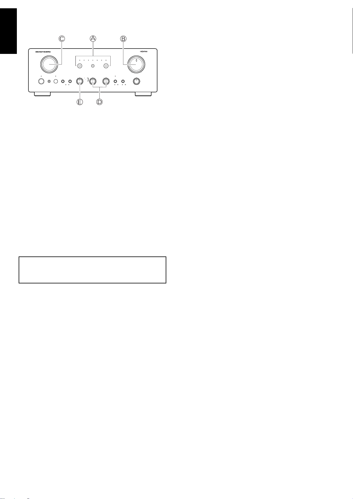
TAPE DECK CD-R(MD) OPERATION
INTEGRATED AMPLIFIER PM7200
INPUT SELECTOR VOLUME
POWER ON/OFF 1 2SPEAKERSSTANDBYPHONES
OFF
REC SELECTOR
TAPE PHONO CD
TUNER AUX1 AUX2
TAPE
CD-R/MD
CD-R/MDMUTE
BASS
SOURCE
SOURCE DIRECT
OFFONOFFON
+
-
R
L
+
-
CLASS A
OFFON
TREBLE BALANCE
MAXMIN
COPY
TAPE CD-R
CD-R TAPE
ENGLISHFRANÇAIS
Perform the applicable operation on the connected tape
deck.
TO PLAY BACK FROM A TAPE
1. Press TAPE A to the indicator above the switch is lit.
2. Play a tape on the tape deck.
DEUTSCHNEDERLANDSESPAÑOLITALIANOPORTUGUÊSSVENSKADANSK
3. Use VOLUME B to adjust volume.
4. Use BASS and TREBLE D to adjust the tone.
NOTE:
You can play back from a tape regardless of the INPUT SELECTOR C setting.
TO RECORD TO A TAPE
1. Set INPUT SELECTOR C to PHONO, CD, TUNER, AUX 1, or
AUX 2 to select the source you want to record from.
2. Use the REC SELECTOR E to specify the type of recording
you want to perform.
3. Start play on the selected source.
4. Perform the applicable operation on the connected tape deck
to record the output from the selected source.
USING THE REC SELECTOR
Use the REC SELECTOR E to specify the type of recording you
want to perform.
1. The OFF setting cuts off all signal output from the REC OUT
jacks. Note that REC SELECTOR Eshould normally be in the
OFF setting except when you are recording to tape. The OFF
setting shortens the signal path within the amplifier, which
minimizes crosstalk and other factors that can cause deterioration of the sound.
2. SOURCE sets up for recording the signal from the source selected by INPUT SELECTOR C.
3. COPY sets up for recording from TAPE to CD-R, or from CD-R
to TAPE. You can listen to the output from another source while
recording in the COPY position by selecting the source you want
with INPUT SELECTOR C.
NOTE:
The SOURCE DIRECT switch must be turned off (raised) in order
to record to a tape deck. Recording will not possible when
SOURCE DIRECT is turned on (depressed).
6

REMOTE CONTROL UNIT RC 8000PM
ON OFF
SYSTEM POWER
SOURCE
ON/OFF
AMP
PHONO
CD TUNER CD-R
AUX1 AUX2 TAPE MD
1 2 3 A, F/P
4 5 6 B, -/--
7 8 9 MODE
— 0 + MEMO
SCROLL CANCEL
TEXT
OPEN/
CLOSE
TIME
1—MODE—2
MUTE
RC8000PM
SYSTEM REMOTE CONTROLLER
VOLUME
The RC8000PM remote control unit can be used to control any
Marantz AV equipment that has a remote sensor, as well as other
Marantz equipment connected to the main equipment’s remote
control bus. The buttons of the remote control unit are arranged on
the control panel according to functional groups as shown in the
illustration below.
See the relevant user manuals for details on combination equipment
as operation content may differ depending on the equipment
combined.
CD BUTTON
The following are the functions assigned to control buttons after the
CD amplifier source button is pressed.
BUTTON NAME FUNCTION
Play
Fast-forward
Fast-reverse
None
Stop
Pause
OPEN/CLOSE Open/Close
+ Next Track
– Previous Track
A, F/P Disc Select down
B, –/–– Disc Select up
MODE Auto Music Scan (AMS)
MEMO Store
TEXT (MODE 1) Text
TIME (MODE 2) Time
Next Track
Previous Track
SCROLL Scroll
CANCEL Cancel
ENGLISHFRANÇAIS
DEUTSCHNEDERLANDSESPAÑOLITALIANOPORTUGUÊSSVENSKADANSK
z Amplifier Source Buttons*
U
se these buttons to select the amplifier’s program source.
x Player Operation Buttons
Use these buttons to control operation of a VCR, CD player,
etc.
c Numeric Key Pad
Use these buttons to input buttons for control of a tuner, CD
player, etc.
v Player/Tuner Auxiliary Operation Buttons
Use these buttons to control the mode switching and track jump
operations of a tuner, CD, etc.
b Amplifier Operation Buttons
Use these buttons to control power on/Standby, volume level, etc.
* Pressing an amplifier source button in group z to select a source
SYSTEM POWER ON : Power supply is ON for the Unit.
SYSTEM POWER OFF : Power supply is OFF for the Unit.
SOURCE ON/OFF :
Power supply is ON/OFF for equipment selected by
the z button.
MUTE : Mutes amp(this equipment’s) sound.
VOL : Increases this equipment’s volume.
VOL : Decreases this equipment’s volume.
causes the buttons in groups x, c and v to take on functions
to control the selected source equipment (except for PHONO
and AMP button). The following tables shows the functions of
buttons in these groups for each available amplifier source.
TUNER BUTTON
The following are the functions assigned to control buttons after the
TUNER amplifier source button is pressed.
BUTTON NAME FUNCTION
None
Tuning up
Tuning down
None
None
None
OPEN/CLOSE None
+ Preset up
– Preset down
A, F/P Channel/Frequency/Preset
B, –/–– 1/2/3 Digits
MODE Stereo/Mono
MEMO Store
TEXT (MODE 1) None
TIME (MODE 2) None
None
None
SCROLL Display
CANCEL Cancel
7

CD-R BUTTON
The following are the functions assigned to control buttons after the
CD-R amplifier source button is pressed.
ENGLISHFRANÇAIS
BUTTON NAME FUNCTION
Play
Fast-forward
Fast-reverse
None
Stop
Pause
OPEN/CLOSE Open/Close
+ Next track
– Previous track
A, F/P None
B, –/–– None
MODE Auto Music Scan (AMS)
DEUTSCHNEDERLANDSESPAÑOLITALIANOPORTUGUÊSSVENSKADANSK
MEMO Store
TEXT (MODE 1) Text
TIME (MODE 2) Time
Next track
Previous track
SCROLL Scroll
CANCEL Cancel
AUX 2 BUTTON
The following are the functions assigned to control buttons after the
AUX 2 amplifier source button is pressed.
BUTTON NAME FUNCTION
VCR Play
VCR Fast-forward
VCR Rewind
None
VCR Stop
VCR Pause
OPEN/CLOSE Tape Eject
+ Step up
– Step down
A, F/P Channel/Preset
B, –/–– 1/2/3 Digits
MODE Sound Select
MEMO Store (Memo Rew.)
TEXT (MODE 1) Text ↔ TV Station
TIME (MODE 2) Scroll Display (Time)
VCR Fast Run FWD
VCR Fast Run REV
SCROLL None
CANCEL None
AUX 1 BUTTON
The following are the functions assigned to control buttons after the
AUX 1 amplifier source button is pressed.
BUTTON NAME FUNCTION
VCR Play
VCR Fast-forward
VCR Rewind
None
VCR Stop
VCR Pause
OPEN/CLOSE Tape Eject
+ Channel/Program up
– Channel/Program down
A, F/P Channel/Frequency/Preset
B, –/–– 1/2/3 Digits
MODE Sound Select
MEMO Store
TEXT (MODE 1) TV Station ↔ Text
TIME (MODE 2) Scroll Display (Time)
VCR Fast Run FWD
VCR Fast Run REV
SCROLL None
CANCEL None
TAPE BUTTON
The following are the functions assigned to control buttons after the
TAPE amplifier source button is pressed.
BUTTON NAME FUNCTION
Play
Fast-forward
Rewind
Direction Switch
Stop
Pause
OPEN/CLOSE Eject
+ Next
– Previous
A, F/P Deck A
B, –/–– Deck B
MODE Auto Music Scan (AMS)
MEMO Store
TEXT (MODE 1) Scroll Display (Text)
TIME (MODE 2) Scroll Display (Time)
Next
Previous
SCROLL None
CANCEL Cancel
8

MD BUTTON
The following are the functions assigned to control buttons after the
MD amplifier source button is pressed.
BUTTON NAME FUNCTION
Play
Fast-forward
Rewind
None
Stop
Pause
OPEN/CLOSE Eject
+ Next
– Previous
A, F/P Edit
B, –/–– Enter
MODE Monitor
MEMO Store
TEXT (MODE 1) None
TIME (MODE 2) Time
Next
Previous
SCROLL Scroll
CANCEL Delete
USING THE REMOTE CONTROL UNIT
When operating the remote control unit (RC8000PM), point its transmitter directly at the remote sensor, which is located on the front of
the amplifier. Make sure the remote control unit is no further than
about 5 meters from the remote sensor. Remote control operation
may not be possible if the remote control unit’s transmitter is not
pointing directly at the remote sensor, or if there is an obstruction
between the transmitter and sensor.
Remote Control Operating Range
Approximately 5 meters
60°
Remote Control Unit RC8000PM
REMOTE CONTROL UNIT BATTERIES
Remote control unit batteries should last for about one year under
normal conditions. Replace batteries as soon as possible whenever
they show signs of running low. Also, be sure to remove the batteries
if you do not plan to use the remote control unit for a long time.
ENGLISHFRANÇAIS
DEUTSCHNEDERLANDSESPAÑOLITALIANOPORTUGUÊSSVENSKADANSK
TO LOAD REMOTE CONTROL UNIT BATTERIES
(1) Remove the battery compartment cover.
Back of Remote Control Unit
(RC8000PM)
(2) Load two batteries, making sure their positive (+) and
negative (–) ends are facing correctly.
Two AA-size (R6) (UM-3) batteries
(3) Slide the battery compartment cover back into place and
press until it clicks shut.
9

CARE AND MAINTENANCE
This section describes care and maintenance that you must perform in order to make sure your Marantz amplifier performs at the
ENGLISHFRANÇAIS
level for which it is designed. Be sure to unplug the amplifier from
the mains supply before any care and maintenance.
NORMAL CLEANING
The exterior of your amplifier will last indefinitely with proper care
and cleaning. For normal cleaning, wipe exterior surfaces with a
soft, lint-free cloth.
IMPORTANT:
Any of the following will mar the finish of your amplifier and should
never be used for cleaning.
— Scouring pads, steel wool, abrasive powders
— Harsh chemical agents (such as a lye solution)
— Alcohol, thinners, benzine, insecticide, or other volatile agents.
SPECIAL CLEANING
Should it amplifier ever become so soiled that normally cleaning is
DEUTSCHNEDERLANDSESPAÑOLITALIANOPORTUGUÊSSVENSKADANSK
not enough, use the following procedure for cleaning.
1. Prepare a cleaning solution of one part mild neutral liquid deter-
gent and six parts water.
2. Moisten a soft, lint-free cloth in the cleaning solution and then
wring out all excess moisture from the cloth.
3. Wipe off the amplifier with the damp cloth.
4. Dry the amplifier by wiping it with a soft dry cloth.
REPLACING THE FUSE
(for variable mains voltage version)
Should the fuse blow, immediately unplug the amplifier from the
mains supply. Replace the fuse with a new one of the same type
and rating. If the fuse blows again after the amplifier is turned on,
take the amplifier to an authorized Marantz service provider.
IMPORTANT:
Using a fuse with a higher rating or slower action does not protect
the amplifier and invalidates your warranty.
REPAIRS
Only the most competent and qualified serviced technicians should
be allowed to service this amplifier. Marantz and its factory-trained
warranty personnel have the special knowledge and facilities required for the repair and calibration of this amplifier. After expiration of the warranty period, repairs can be performed for a separate
charge.
Whenever you experience problems, first try to solve the problem
yourself using the troubleshooting procedures provided on this page.
If this does not work, contact your original dealer or write directly to
your nearest service provider as listed on the Marantz Authorised
Service Station list. When you write, be sure to include the model
and serial number of your amplifier, together with a detailed
description of the problem.
TROUBLESHOOTING
Whenever you have a problem with the amplifier, check the following points before requesting service. What may seem to be a serious
malfunction is often the result of a simple operational error. If you
still have problems, contact your original dealer or write directly to
your nearest service provider as listed on the Marantz Authorised
Service Station list.
The amplifier does not operate and indicators do not light.
1. Check to see if the power cord is correctly inserted into a power
outlet.
Indicators light, but the amplifier does not operate.
1. Check the SELECTOR and VOLUME settings.
2. Check to see if the supplied connecting pins are correctly in-
serted into the PROCESSOR IN/OUT jacks.
Sound is being produced by only one speaker.
1. Check the BALANCE setting.
2. Turn off the amplifier and switch the connections of the left and
right speaker cords. If the same speaker still does not produce
sound, it probably means that the connection cord or the speaker
itself is defective.
Considerable humming is produced when playing from a
turntable.
1. Check to see if the plugs from the turntable are properly con-
nected to the amplifier’s PHONO jacks.
2. Connect the turntable’s ground wire to the GND terminal on the
rear panel of the amplifier. If the ground wire is already
connected, try disconnecting it.
3. Check to make sure that the turntable’s phono cartridge is se-
curely attached to the tone arm.
4. Unplug the amplifier’s power cord, turn over the plug so the two
blades go into opposite holes, and plug it back in.
Cannot perform remote operation.
1. Make sure the remote control unit’s (RC8000PM) transmitter is
pointed directly as the amplifier’s remote sensor when you perform a remote control unit operation.
2. Check for obstructions between the remote control unit’s trans-
mitter and the amplifier’s remote sensor.
3. Check the batteries of the remote control unit.
4. Make sure there is no strong light (from a window or other source)
shining on the amplifier’s remote sensor.
5. Check to see if there is an RCA cord connected to the REMOTE
CONTROL IN jack on the amplifier’s rear panel.
10

MODEL PM7200 TECHNICAL SPECIFICATIONS
INTEGRATED AMPLIFIER PM7200
INPUT SELECTOR VOLUME
POWER ON/OFF 1 2SPEAKERSSTANDBYPHONES
OFF
REC SELECTOR
TAPE PHONO CD
TUNER AUX1 AUX2
TAPE
CD-R/MD
CD-R/MDMUTE
BASS
SOURCE
SOURCE DIRECT
OFFONOFFON
+
-
R
L
+
-
CLASS A
OFFON
TREBLE BALANCE
MAXMIN
COPY
TAPE CD-R
CD-R TAPE
440
327.5 2720
374.5
14613
159
Power output (class AB operation)
RMS 8 ohms (20 Hz-20 kHz) ..........................................................................................................95 W
DIN 8 ohms .................................................................................................................................... 105 W
THD at 8 ohms RMS rated output ................................................................................................ 0.03%
Damping factor................................................................................................................................... 150
Power output (classA operation)
RMS 8 ohms (20 Hz-20 kHz) ..........................................................................................................25 W
DIN 8 ohms ...................................................................................................................................... 28 W
THD at 8 ohms RMS rated output ............................................................................................... 0.03 %
Damping factor................................................................................................................................... 150
IHF dynamic power (class AB operation)
8 ohms ............................................................................................................................................ 120 W
IHF dynamic power (classA operation)
8 ohms .............................................................................................................................................. 35 W
Magnetic cartridge input
Input sensitivity impedance......................................................................................... 2.5 mV/47 kOhm
Accuracy of frequency response to IEC RIAA ............................................................................. 0.5 dB
Signal to noise ratio ........................................................................................................................ 85 dB
Tuner/CD/Aux/Tape inputs
Input sensitivity impedance........................................................................................ 150 mV/40 kOhm
Signal to noise ratio ........................................................................................................................ 88 dB
Frequency response (–1 dB limits, Source Direct)........................................................ 10 Hz - 50 kHz
Tone characteristic (100 Hz and 10 kHz)...................................................................................... ±8 dB
Channel separation (1 kHz/10 kHz, Source direct) ...........................................................
>80/>70 dB
General
Power Requirements .....................................................................................................230V AC, 50 Hz
Dimensions
Width ...................................................................................................................................... 440 mm
Height..................................................................................................................................... 159 mm
Depth .................................................................................................................................. 374.5 mm
Weight
Unit alone ............................................................................................................................... 12.3 kg
Specifications subject to change without prior notice.
Dimensions
[mm]
75

FIGURES
76

L
PHONO
R
OUT
IN
CD
CD-R/MD
AUX1
TAPE
AUX2
L
PROCESSOR
R
TUNER
IN
OUT
IN
OUT
SYSTEM 1
SYSTEM 2
RL
LR
SYSTEM 1 : 8 - 16 OHMS
SPEAKER SYSTEMS
SYSTEM 2 : 8 - 16 OHMS
SYSTEM 1+2 : 16 OHMS
Processor
Tape Deck
Tuner
Input
Output
Output
Input
Output
CD player
SYSTEM 2
SYSTEM 1
RL
LR
Turntable
NOTE:
Turn the knobs on the speaker terminals by hand.
(Do not use a tool to turn the knobs.)
Loosen the terminal Insert the core
5 mm
Tighten the terminal
Figure 1
77
Connecttion of speaker cable

INTEGRATED AMPLIFIER PM7200
INPUT SELECTOR VOLUME
POWER ON/OFF 1 2SPEAKERSSTANDBYPHONES
OFF
REC SELECTOR
TAPE PHONO CD
TUNER AUX1 AUX2
TAPE
CD-R/MD
CD-R/MDMUTE
BASS
SOURCE
SOURCE DIRECT
OFFONOFFON
+
-
R
L
+
-
TREBLE BALANCE
MAXMIN
CLASS A
OFFON
COPY
TAPE CD-R
CD-R TAPE
PROCESSOR
IN IN
CD-R/MD
TAPE
OUT
AUX2
AUX1
OUT
IN
OUT
TUNER
CD
PHONO
RL
RL
SYSTEM 1 : 8- 16 OHMS
SYSTEM 2 : 8- 16 OHMS
SYSTEM 1 + 2 : 16 OHMS
SPEAKER SYSTEMS
SYSTEM 2R
+ —
L
— +
SYSTEM 1R
+ —
L
— +
IN
OUT
REMOTE
CONTROL
SWITCHED
TOTAL 100W MAX
AC OUTLETS
230V 50HZ
Figure 2
78

COUNTRY COMPANY ADDRESS
ALGERIE Azur 2000 8, Lotissement Ben Hatadi, Alger, Algerie
ARMENIA NGYIG Ltd. 47 A/75 St. Lalaiants, 375000 Yerevan, Armenia
AUSTRALIA QualiFi Pty. Ltd., P.O. Box 350, Mt. Waverley, VIC 3149, Australia
AUSTRIA Huber & Prohaska GmbH Taborstraße 95 / Ladestraße 1, Gebäude Hangartner, A-1200 Wien, Austria
BAHREIN Ambassador Stores P.O. Box 237,141, Government Avenue, Manama,Bahrein
BANGLADESH Target 1078, Ramjoy Mohanja Lane Asadgonj, Chittagong 4000, Bangladesh
BELGIUM Van der Heyden Audio N.V. Brusselbaan 278, 9320 Erembodegem, Belgium
BULGARIA Ariescommerce GmbH Makedonia Blvd. 16, 1606 Sofia, Bulgaria
CANADA Lenbrook Industries Limited 633 Granite Court, Pickering, Ontario
CHINA
CYPRUS Empire Hifi systems Ltd. P.O. Box 5604, Nicosia, Cyprus
CZECH REPUBLIC Audio International Sokolska 41, 67902 Rajecko, OKR,Blansko, Czech Republic
DENMARK Audio Nord Dali Allé 1, 9610 Noerager, Denmark
DUBAI V.V.& SONS P.O. Box 105, Dubai, U.A.E.
EGYPT Solimco 9, El Attibaa St. Doki, Cairo, Egypt
ESTONIA HiFi Club Estonia Ehte 4, 90503 Haapsalu, Estonia
F.Y.R.O.M. T.P. KODI ul.Cedomir Kantargiev 21a, Skopje, Former Yugoslavian Republic of Macedonija
FINLAND Audio Nord Uudenmaankatu 4-6, Helsinki SF-00120, Finland
FRANCE Marantz France A division of Marantz Europe B.V., P.O. Box 301, 92 156 Suresnes Cedex, France
GERMANY Marantz Deutschland Hakenbusch 3, 49078 Osnabrück, Germany
GREECE Adamco S.A. 188, Hippocratous Street, 11471 Athens, Greece
HEADQUARTERS EUROPE: Marantz Europe B.V. P.O. Box 8744, 5605 LS Eindhoven, The Netherlands
HONG KONG Marantz Hong Kong Ltd. Unit 1706, Metroplaza II, 223 Hing Fong Road, Kwai Fong, N.T., Kowloon, Hong Kong
HUNGARY Infovox Ltd. Terez Krt.31, 1067 Budapest, Hungary
ICELAND ID Electronics Ltd. Armula 38, 108 Reykjavik, Iceland
INDIA NOVA Audio Private 8,Punam Co-op.Society 29/30 Road#5, Union Park MUMBAI 400052, India
IRAN Home Co. 5th floor no 878 Philips Building Enghelab ave, P.O. 11365/7844 Tehran, Iran
IRELAND Marantz Ireland Clonskeagh, Dublin 14, Ireland
ISRAEL Elmor Ltd. 52 Heh Beiyar Street, Kikar Hamedina, Tel Aviv, Israel
ITALY Marantz Italy Via Casati 23, 20052 Monza (Milano), Italy, Servizio Consumatori 1678-20026, Numero Verde
IVORY COAST Hifivoir B.P. 2428, Abidjan 01, Ivory Coast
JAPAN Marantz Japan Inc. 35-1 Sagami Ohno 7-Chome, Sagamihara-shi, Kanagawa 228-8505, Japan
KOREA MK Enterprises Ltd. Rm604, Electro-officetel, 16-58. Hangang-ro 3Ga, Yongsan-Ku, Seoul, Korea
KUWAIT alAlamiah Electronics Intl. P.O. Box 8196, Salmiah 22052, Kuwait
LATVIA Ace Ltd. 61, LacPlesa Str., Riga LV 1011, Latvia
LEBANON AZ Electronics S.A., 1, P.O. Box 11 2833, Beirut, Lebanon
LITHUANIA Accapella Ltd. Ausros, Vartu G/5, Pasazo SKG., 2001 Vilnius, Lithuania
MALAYSIA Wo Kee Hong Electronics Sdn. Bhd. 2nd Floor Bangnan Infinite Centre, Lot1, Jalan 13/6, 46200 Petaling Jaya, Selangor Datul Ehsan, Malaysia
MALTA Doneo Co Ltd. 78 The Strand, Sliema SLM07, Malta
MAURITIUS SKR Electronics Ltd. P.O. Box 685, Bell Village, Port Louis, Mauritius
MILITARY MARKET EUROPE PASCO GmbH PO BOX 1280, Sandhausen 69200, Germany
NEW ZEALAND Wildash Audio Systems 14 Malvern Road, Mt. Albert, Auckland, New Zealand
NORWAY Audio Nord Sandkerveien 64, Oslo 0483, Norway
OMAN Mustafa & Jawad Trading CO. P.O. Box 1918, Ruwi, Oman
POLAND Philips Polska Sp. z.o.o. Al.Jerozolimskie 195b, 02 222 Warszawa, Poland
PORTUGAL Corel2 Comércio de Electrónica Lda., Av. Luís Bívar, No 85 A, 1050 Lisboa, Portugal
PROFESSIONAL EUROPE Marantz U.K. Ltd. Kingsbridge House, Padbury Oaks, 575-583 Bath Road, Longford, Middlesex UB7 0EH, U.K.
PROFESSIONAL U.S.A. Marantz Amerika Inc. 1100 Maplewood Drive Itasca, IL 60143, U.S.A.
QATAR Almana & Partners W.W.L. P.O. Box 49, Doha, Qatar
REUNION Vision + 180 Rue du Marechal Leclerc, 97400 Saint Denis, Ile de la Reunion
ROMANIA Nova Music Entertainment 5, Zagazului Str. Bl.1G,apt.18, sector 1,Bucharest, Romania
RUSSIA Absolute Audio 7/2, Montazhnaya Street, 107497 Moscow, Russia
SAUDI ARABIA Adawlia Univ. Electr. Apl P.O. Box 2154, Alkhobar 31952, Saudi Arabia
SINGAPORE Wo Kee Hong Distribution PTE Ltd. 130 Joo Seng Road, #03-02 Olivine Building, Singapore 368357
SLOVAKIA Bis Audio s.r.o. Nam. SNP 10, 96001 Zvolem, Slovakia
SLOVENIA Bofex Smartinska 152, HALA V/3, 61000 Ljubljana, Slovenia
SOUTH AFRICA Coherent Imports (PTY) Ltd. P.O. Box 1614, Alberton, 1450, South Africa
SPAIN Marantz Spain Martinez Villergas 2, Apartado 2065, Madrid 28027, Spain
SRI LANKA The listening Room Mezzanine Floor, The Landmark 385, Galle Road, Colombo - 3, Sri Lanka
SWEDEN Audio Nord Almedalsvagen 4, Gotenborg 402-23, Sweden
SWITZERLAND Sound Company AG Postfach, 8010 Zürich, Switzerland
SYRIA Hamzeh & Partners Hafez Ibrahim Str. No 117, Damascus Shalan, Syria
TAHITI Covecolor Av. Prince Hinoi, Cours de l'union sacré, P.O. Box 2334, Papeete, Tahiti
TAIWAN Pai-Yuing Co. Ltd. 6th No 148 Sung Kiang Road, Taipei 10429, Taiwan R.O.C.
THAILAND MRZ Standard Co. Ltd. 746-750 Mahachai Road, Wangburapa, Bangkok 10200, Thailand
TUNESIA Societe EDEVIG 40, Avenue du Golfe Arabe, El Menzah, 1004, Tunesia
TURKEY Türk Philips Ticaret A.S. Yukari Dudullu Organize sanayi Bolgesi, 2.Cadde no.28, 81260 Umraniye-Istanbul, Turkey
U.K. Marantz U.K. Ltd. Kingsbridge House, Padbury Oaks, 575-583 Bath Road, Longford, Middlesex UB7 0EH, U.K.
U.S.A. Marantz America Inc. 1100 Maplewood Drive Itasca, IL 60143, U.S.A.
YUGOSLAVIA ITM Company Omladinskih Brigada 86, 11070 Belgrade, Yugoslavia
www.marantz.com
Guang Chang Audio International Co., Ltd.
No.38 Yushan Road, ShiQiao, Pan Yu, Guang Dong, China
is a registered trademark.
2002/10 MITs 20AW851310Printed in China
 Loading...