

Page 1

ESPAÑOL FRANÇAIS ENGLISH
Integrated Amplifier
PM5003
Page 2
CAUTION
RISK OF ELECTRIC SHOCK
DO NOT OPEN
CAUTION: TO REDUCE THE RISK OF ELECTRIC SHOCK,
DO NOT REMOVE COVER (OR BACK) NO USER-SERVICEABLE
PARTS INSIDE REFER SERVICING TO QUALIFIED
SERVICE PERSONNEL
The lightning flash with arrowhead symbol within an equilateral triangle is
intended to alert the user to the presence of uninsulated “dangerous voltage”
within the product’s enclosure that may be of suffi cient magnitude to constitute
a risk of electric shock to persons.
The exclamation point within an equilateral triangle is intended to alert the
user to the presence of important operating and maintenance (servicing)
instructions in the literature accompanying the product.
WARNING
TO REDUCE THE RISK OF FIRE OR ELECTRIC SHOCK,
DO NOT EXPOSE THIS APPLIANCE TO RAIN OR MOISTURE.
NOTE:
This equipment has been tested and found to comply
with the limits for a Class B digital device, pursuant
to Part 15 of the FCC Rules. These limits are
designed to provide reasonable protection against
harmful interference in a residential installation. This
equipment generates, uses and can radiate radio
frequency energy and, if not installed and used in
accordance with the instructions, may cause harmful
interference to radio communications. However,
there is no guarantee that interference will not occur
in a particular installation. If this equipment does
cause harmful interference to radio or television
reception, which can be determined by turning the
equipment off and on, the user is encouraged to
try to correct the interference by one or more of the
following measures:
This Class B digital apparatus complies with
Canadian ICES-003.
- Reorient or relocate the receiving antenna.
- Increase the separation between the equipment
and receiver.
- Connect the equipment into an outlet on a
circuit different from that to which the receiver is
connected.
- Consult the dealer or an experienced radio/TV
technician for help.
NOTE:
Changes or modifi cations may cause this unit to fail
to comply with Part 15 of the FCC Rules and may
void the user's authority to operate the equipment.
Cet appareil numerique de la Classe B est conforme
a la norme NMB-003 du Canada.
CAUTION:
TO PREVENT ELECTRIC SHOCK, MATCH WIDE BLADE OF
PLUG TO WIDE SLOT, FULLY INSERT.
ATTENTION:
POUR EVITER LES CHOCS ELECTRIQUES, INTRODUIRE
LA LAME LA PLUS LARGE DE LA FICHE DANS LA BORNE CORRESPONDANTE DE LA PRISE ET POUSSER JUSQU’AU FOND.
DECLARATION OF CONFORMITY
This device complies with Part 15 of the FCC rules. Operation is subject to the
following conditions: (1) This device may not cause harmful interference, and (2) this
device must accept any interference received, including interference that may cause
undesired operation.
U.S. Responsible Party: Marantz America, Inc.
100 Corporate Drive,
Mahwah, NJ, 07430, U.S.A.
TEL: 201-762
Type of Product:
Model:
-6500
Integrated Amplifier
PM5003
Page 3

IMPORTANT SAFETY
INSTRUCTIONS
READ BEFORE OPERATING EQUIPMENT
This product was designed and manufactured to meet strict quality and safety standards.
There are, however, some installation and operation precautions which you should be particularly
aware of.
1. Read these instructions.
2. Keep these instructions.
3. Heed all warnings.
4. Follow all instructions.
5. Do not use this apparatus near water.
6. Clean only with dry cloth.
7. Do not block any ventilation openings. Install in accordance with the manufacture's
instructions.
8. Do not install near any heat sources such as radiators, heat registers, stoves, or other
apparatus (including amplifi ers) that produce heat.
9. Do not defeat the safety purpose of the polarized or grounding-type plug. A polarized plug
has two blades with one wider than the other. A grounding type plug has two blades and
a third grounding prong. The wide blade or the third prong are provided for your safety.
If the provided plug does not fi t into your outlet, consult an electrician for replacement of
the obsolete outlet.
10. Protect the power cord from being walked on or pinched particularly at plugs,
convenience receptacles, and the point where they exit from the apparatus.
11. Only use attachments/accessories specifi ed by the manufacturer.
12. Use only with the cart, stand, tripod, bracket, or table specified by the manufacturer,
or sold with the apparatus. When a cart is used, use caution when moving the cart/
apparatus combination to avoid injury from tip-over.
Additional Safety Information!
• This product should not be placed in a built-in installation such as a bookcase or rack unless
proper ventilation is provided or the manufacturer’s instructions have been adhered to.
• Apparatus shall not be exposed to dripping or splashing and that no objects filled with
liquids, such as vases, shall be placed on the apparatus.
• When the switch is in the OFF position, the apparatus isn’t completely switched-off from the
MAINS.
• The equipment shall be installed near the power supply so that the power supply is easily
accessible.
• Do not touch hot areas, especially around the “hot surface mark” during and immediately
after use.
• During and immediately after use, this product is hot in areas other than the controls and
rear panel connection jacks. Do not touch hot areas, especially around the “hot surface
mark” and the top panel. Contact with hot areas can cause burns.
Hot surface mark
• Do not expose the unit and batteries to excessive heat such as direct sunlight, fi re or the
like.
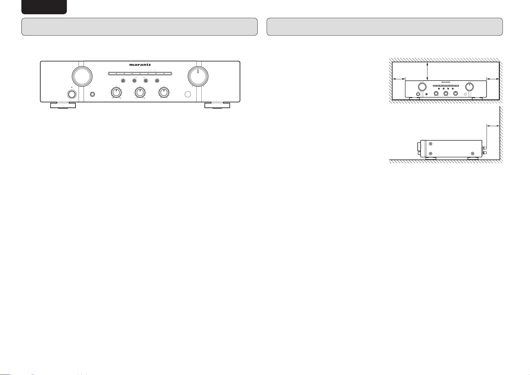
• Make a space of about 8 inchs (0.2 m) around the unit.
13. Unplug this apparatus during lightning storms or when unused for long periods of time.
14. Refer all servicing to qualified service personnel. Servicing is required when the
apparatus has been damaged in any way, such as power-supply cord or plug is damaged,
liquid has been spilled or objects have fallen into the apparatus, the apparatus has been
exposed to rain or moisture, does not operate normally, or has been dropped.
AMP_080708U2
Page 4
ENGLISH
INTRODUCTION
Thank you for selecting the Marantz PM5003 Integrated amplifier for your Audio system.
Please read these operating instructions carefully. W e recommend that you read the entire user guide before
you attempt to connect or operate the amplifier.
After you have reviewed the contents of this manual,we suggest that you make all system connections
before you attempt to operate the unit.
7
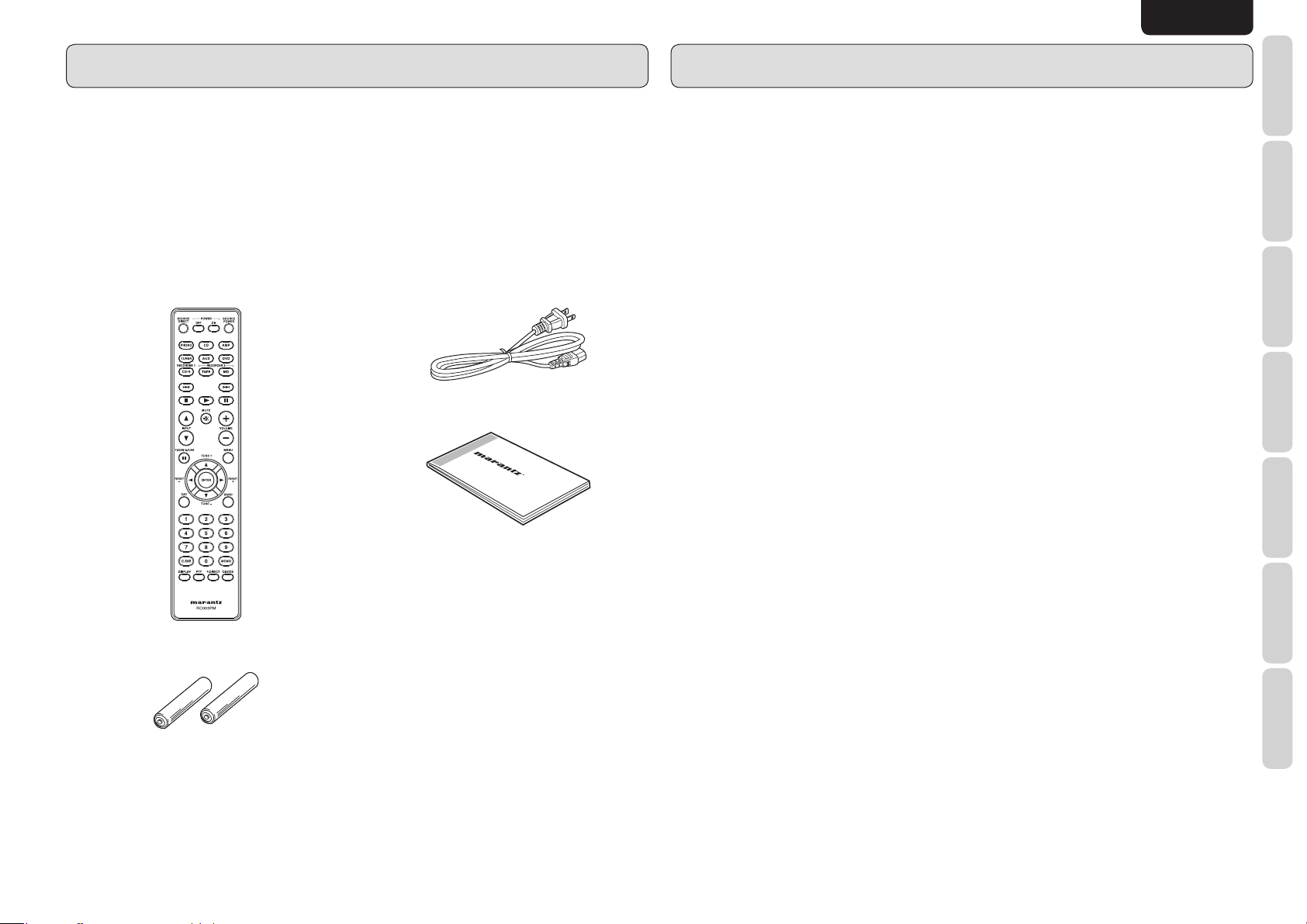
Accessories check
Before use, check the below accessories were included in the package.
• Remote controller
• Size “AAA” batteries x 2
• AC power cable
• User Guide
• Warranty Card
USA × 1
Canada × 1
CONTENTS
FEA TURES ......................................................................................................2
BEFORE USE ..................................................................................................2
NAMES AND FUNCTIONS ..............................................................................4
FRONT PANEL ........................................................................................................ 4
REMOTE CONTROLLER ........................................................................................ 5
REAR PANEL ........................................................................................................... 6
BASIC CONNECTIONS ...................................................................................7
CONNECTION OF AUDIO COMPONENTS ............................................................ 7
CONNECTION OF SPEAKER SYSTEMS ............................................................... 8
CONNECTION OF AC POWER CABLE .................................................................. 8
BASIC OPERATION ........................................................................................9
OPERATION PROCEDURES .................................................................................. 9
RECORDER OPERATION .......................................................................................9
ADVANCED CONNECTION ..........................................................................10
CONNECTING THE REMOTE CONTROL JACKS ............................................... 10
REMOTE CONTROLLER OPERATION ........................................................11
REMOTE CONTROL CODE SETTING ................................................................. 12
TROUBLESHOOTING ...................................................................................12
OTHERS .........................................................................................................13
TECHNICAL SPECIFICATIONS ............................................................................ 13
FUNCTIONS
NAMES AND
BASIC
CONNECTIONS
BASIC
OPERATION
ADVANCED
CONNECTION
OPERATION
REMOTE CONTROLLER
TROUBLESHOOTING
1
OTHERS
Page 5
ENGLISH
FEATURES
INTEGRATED AMPLIFIER PM5003INTEGRATED AMPLIFIER PM5003
STANDBYSTANDBY
POWER ON/OFFPOWER ON/OFF
INPUT SELECTORINPUT SELECTOR
PHONESPHONES
SOURCE DIRECTSOURCE DIRECT
BASSBASS
• Current feedback amplifi er for both pre-amplifi er and power amplifi er
• Wide range, high speed playback for super audio sources
• Improved and optimized the circuit design, parts and pattern wiring
• Input buffer circuit for high S/N ratio and high channel separation
• Active fi lter type tone control circuit
• Source direct function for purity audio playback
• Phono equalizer amplifi er (for MM cartridge)
• System remote control
CDCDPHONOPHONO TUNERTUNER
BB
AA
SPEAKERSSPEAKERS
TREBLETREBLE BALANCEBALANCE
RECORDERRECORDER
MUTEMUTE11AUX/DVDAUX/DVD 22
LOUDNESSLOUDNESS
LL RR
VOLUMEVOLUME
MINMIN
MAXMAX
BEFORE USE
This section must be read before any connection is
made to the mains supply.
7
Equipment mains working
setting
Y our Marantz product has been prepared to comply
with the household power and safety requirements
that exist in your area.
PM5003 can be powered by 120V AC only.
7
Copyright
Recording and playback of any material may
require consent. For further information refer to the
following:
— Copyright Act 1956
— Dramatic and Musical Performers Act 1958
— Performers Protection Acts 1963 and 1972
— Any subsequent statutory enactments and
orders
7
Do not locate in the following
places
To ensure long-lasting use, do not locate the
PM5003 where:
• Exposed to direct sunlight.
• Near to sources of heat such as heaters.
• Highly humid or poorly ventilated.
• Dusty.
• Subjected to mechanical vibrations.
• On wobbly, inclined or otherwise unstable
surfaces
• Radiated heat is blocked such as in cramped
audio racks.
To ensure proper heat radiation, ensure the below
clearance from walls and other equipment.
Left
8 inchs (0.2 m)
or more
7
Keep objects off
INPUT SELECTORINPUT SELECTOR
STANDBYSTANDBY
POWER ON/OFFPOWER ON/OFF
PHONESPHONES
Above
8 inchs (0.2 m)
or more
SOURCE DIRECTSOURCE DIRECT
BASSBASS
INTEGRATED AMPLIFIER PM5003INTEGRATED AMPLIFIER PM5003
CDCDPHONOPHONO TUNERTUNER
AA
SPEAKERSSPEAKERS
TREBLETREBLE BALANCEBALANCE
RECORDERRECORDER
MUTEMUTE11AUX/DVDAUX/DVD 22
VOLUMEVOLUME
LOUDNESSLOUDNESS
BB
MINMIN
LL RR
Right
8 inchs (0.2 m)
or more
MAXMAX
Rear
8 inchs (0.2 m)
or more
Keep objects off the PM5003. Blocking the vent can
result in accident and damage.
7
Do not touch hot spots during
and Immediately after use
During and immediately after use, the PM5003
is hot in areas other than the controls and rear
panel connection jacks. Do not touch hot spots and
especially the top panel. Contact with hot areas can
cause burns.
2
Page 6

BEFORE USE
ENGLISH
7
For use of Remote controller
• Loading batteries
Before using the remote controller for the first time,
load the batteries in the remote controller. The
batteries provided are used to verify the operations
of the remote controller only.
1. Remove the battery cover.
2. Insert the batteries with correct +/– orientation.
3. Close the battery cover until it clicks shut.
7
Cautions on handling batteries
Misuse of the batteries can result in electrolyte
leakage, rupturing, corrosion, etc.
Bear in mind the following points when using
batteries.
• Remove the batteries from the remote control
unit if the unit is not going to be used for a
prolonged period (a month or more).
• Do not use an old battery together with a new
one.
• Insert the batteries while ensuring that their
ª and · poles are properly aligned with the
corresponding markings on the remote control
unit.
• Batteries with the same shape may have different
voltages. Do not use different types of batteries
together.
• If electrolyte has leaked, thoroughly wipe the
inside of the battery compartment, and then
insert new batteries.
• When batteries which are no longer required
are to be discarded, follow the directions
(regulations) laid down by the local authorities in
the area concerned for their disposal.
7
Operatable range of Remote
controller
Operate the unit with the remote controller within
the range of the illustration below.
Approx. 16.4 ft. (5 m)
Remote controller
Caution
• Do not allow direct sunlight, an inverter
fluorescent light or other strong source of light to
shine onto the player’s infrared receptor window.
Otherwise, the operation of the remote controller
may be disabled.
• Bear in mind that operating the remote controller
may cause other devices operated by infrared
rays to be operated by mistake.
• The remote controller cannot be operated if the
space between the controller and the player’s
infrared receptor window is obstructed.
• Do not place any objects on top of the remote
controller.
Doing so may cause one or more buttons to be
held down which will cause the batteries to run
down.
3
Page 7

NAMES AND
PHONES
MIN
MAX
LOUDNESS
VOLUME
MUTE
1
AUX/DVD
RECORDER
CD
PHONO
TUNER
INPUT SELECTOR
INTEGRATED AMPLIFIER PM5003
R
BASS
POWER ON/OFF
TREBLE
BALANCE
STANDBY
B
SOURCE DIRECT
SPEAKERS
FUNCTIONS
ENGLISH
NAMES AND FUNCTIONS
FRONT PANEL
CONNECTIONS
BASIC
OPERATION
BASIC
CONNECTION
ADVANCED
REMOTE CONTROLLER
q POWER SWITCH
OPERATION
TROUBLESHOOTING
OTHERS
Pressing once switches the power ON, and
pressing again switches it OFF.
If the POWER switch is in the ON position,
the power of this unit can be turned ON/OFF
by pressing the POWER button on the remote
controller.
w STANDBY INDICATOR
Lights up when the unit is in the standby mode.
e INPUT SELECTOR
Selects the program source to be recorded or
played from the PHONO, TUNER, CD, AUX/
DVD, RECORDER 1 (CD-R), and RECORDER
2 (MD/TAPE).
q w r yet u
STANDBY
POWER ON/OFF
INPUT SELECTOR
PHONES
PHONO
SOURCE DIRECT
BASS
INTEGRATED AMPLIFIER PM5003
CD
TUNER
AASPEAKERS
AUX/DVD
TREBLE
1
B
r SOURCE DIRECT button and
indicator
This button turns SOURCE DIRECT mode ON
and OFF. When SOURCE DIRECT is ON, the
center of the button is lit. In the Source Direct
mode, the audio signals bypass the tone control
circuit.
t FUNCTION INDICATORS
One of the indicators lights up to indicate
the input source selected with the INPUT
SELECTOR.
LOUDNESS
22RECORDER
MUTE
BALANCE
LLR
o!3 !0!1!2
VOLUME
MIN
MAX
i
y MUTE INDICATOR
Light up when the MUTE button in the remote
controller is pressed.
NOTE:
Be sure to check the VOLUME control
setting before pressing this switch to cancel
muting. If the muting is canceled while the
volume setting is high, the speakers could
be damaged.
u VOLUME CONTROL
Adjusts the volume level. Turn the knob clockwise
to increase the volume.
i REMOTE SENSOR
The remote sensor receives the infrared
commands from the remote controller. When
an infrared signal is received from the remote
controller. The remote controller must always be
pointed directly at the remote sensor.
o BALANCE CONTROL
Turn the knob to correct an unbalanced program
source such as stereo broadcast or to vary the
output level of the left or right channel. Note
that, if the BALANCE control is turned fully in
one direction, the sound will not be heard from
the speaker on the other side.
!0 LOUDNESS button and indicator
This button turns LOUDNESS ON and OFF.
When LOUDNESS is ON, the center of the
button is lit. The LOUDNESS cmpensates for
human hearing characteristics by boosting the
bass and treble response at low volume levels
to achieve a more pleasing tonal balance.
!1 SPEAKERS A/B buttons and
indicators
These buttons turn the speaker output to
the speakers connected to the SPEAKER
SYSTEMS A/B terminals on the rear panel
ON and OFF. When speaker output is ON,
the center of the button is lit. To listen with
headphones, turn speaker output OFF.
!2 BASS AND TREBLE TONE
CONTROLS
Adjusts the tone by controlling the levels of two
frequency bands. Turn each control toward (+)
to enhance the corresponding frequency band,
or toward (–) to attenuate it.
TREBLE: Adjusts the high frequency level.
BASS: Adjusts the low frequency level.
!3 PHONES JACK
Insert the standard phone plug of the
headphones into this jack.
4
Page 8

NAMES AND FUNCTIONS
ENGLISH
REMOTE CONTROLLER
Using this remote controller, you can control the
PM5003 and Marantz CD players, DVD players,
tuners, tape decks etc. that have a remote control
receptor. The operations possible by remote
controller may differ with each component; therefore
see the instruction manual that came with the
component.
The remote controller buttons are laid out as shown
below.
v
x
z
b
c
b
z POWER ON/STANDBY buttons
a. MAIN POWER ON button
Turns the PM5003 power on when it is in the
standby mode.
b. MAIN POWER STANDBY button
Sets the PM5003 power to the standby
mode when it is set to the power-on mode.
c. SOURCE POWER button
Switching the mode of a CD player, tuner,
CD-R or other Marantz component equipped
with a power standby function between
power-on and standby is enabled by pressing
this button after the FUNCTION SELECT
button corresponding to the component has
been pressed.
When this button is pressed after pressing
the TUNER button, the tuner’s power is
turned on; when it is pressed again, the
tuner is set to the standby mode.
When this button is pressed after pressing
the AMP button, the PM5003 is switched
from the power-on mode to the standby
mode or vice versa.
* The remote controller cannot be used to
turn the primary power of the amplifier ON
and OFF.
x Input selector buttons
• Input source Buttons
These buttons are for directly selecting the
input source.
Caution
Some input jacks of this unit and the
corresponding input selector buttons on the
remote controller differ, as shown below.
The unit
AUX/DVD AUX, DVD
RECORDER2 TAPE, MD
For the input sources shown in the table above,
although the same jacks are used for two
types of sources on the unit, separate buttons
are provided on the remote controller.
When using the remote controller for operation
of a Marantz component connected to the
unit, select the input source first, then perform
operations.
• INPUT 5 Button
This button is for forward-feeding the input
source indications to select a desired
source.
The input source indication, which is
displayed on the function indicator on the
main frame, is fed to the right.
• INPUT ∞ Button
This button is for backward-feeding the
input source indications to select a desired
source.
The input source indication, which is
displayed on the function indicator on the
main frame, is fed to the left.
Buttons on the
remote controller
c VOLUME adjustment buttons
• MUTE Button
This button activates the mute function.
Pressing this button again releases the
MUTE function.
The MUTE function can also be released by
pressing either the VOLUME + or – buttons.
• VOLUME + Button
This button increases the volume level.
• VOLUME – Button
This button decreases the volume level.
v SOURCE DIRECT button
This button turns SOURCE DIRECT mode ON
and OFF.
b Component operating buttons
These buttons are for performing basic
operations of a Marantz CD player, DVD player ,
etc. The function of each button changes to
match the component selected as the input
source using the input selector buttons.
FUNCTIONS
NAMES AND
BASIC
CONNECTIONS
BASIC
OPERATION
ADVANCED
CONNECTION
OPERATION
REMOTE CONTROLLER
TROUBLESHOOTING
5
OTHERS
Page 9

ENGLISH
R
OUT
IN
OUT
IN
L
R
L
R
L
R L
R
L
PHONO
TUNERCDCD
AUX /
DVD
RECORDER 2
(
MD /
TAPE
)
RECORDER 1
(
CD-R
)
SPEAKER SYSTEMS
REMOTE
CONTROL
FLASHER
IN
SYSTEM B
CLASS 2 WIRING
SYSTEM A
AC OUTLETS
120V 60Hz
UNSWITCHED
120W 1A MAX
SWITCHED
120W 1A MAX
IN
OUT
AC IN
PHONO
GND
qw i o!0!1!
e r t y u
NAMES AND
FUNCTIONS
NAMES AND FUNCTIONS
REAR PANEL
CONNECTIONS
BASIC
OPERATION
BASIC
PHONO
PHONO
!1 AC OUTLETS
Connect the AC power cord of component such
as a DVD or CD player to this outlet.
The marked SWITCHED provides power only
when the PM5003 is turned on and is useful for
components which you use every time you play
your system.
GND
TUNER
AUX
DVD
RECORDER 1
IN
RECORDER 2
MD
CD-R
OUT
TAPE
OUT
IN
SPEAKER SYSTEMS
CLASS 2 WIRING
SYSTEM A
SYSTEM B
FLASHER
SWITCHED
REMOTE
CONTROL
IN
OUT
120W 1A MAX
IN
UNSWITCHED
120W 1A MAX
AC OUTLETS
120V 60Hz
AC IN
Caution:
• In order to avoid potential turn-off thumps,
anything plugged into these outlets should be
powered up before the PM5003 is turned on.
• The capacity of this AC outlet is 120W. Do not
connect devices that consume electricity more
than the capacity of this AC outlet. If the total
power consumption of the connected devices
exceeds the capacity, the protection circuit shuts
down the power supply.
CONNECTION
ADVANCED
q PHONO INPUT JACKS
REMOTE CONTROLLER
Connect the output jacks of a turntable to these
OPERATION
jacks.
w GND (GROUND) TERMINAL
Connect the grounding wire from the turntable
to this terminal.
TROUBLESHOOTING
e TUNER INPUT JACKS
Connect the output jacks of the tuner to these
jacks.
r CD PLAYER INPUT JACKS
OTHERS
Connect the output jacks of a Compact Disc
player to these jacks.
2
!2 AC IN socket
Connect the supplied AC power cable to this
socket and a power outlet.
t AUX/DVD INPUT JACKS
These are auxiliary input jacks which can be used
to connect the audio outputs of AV components
such as DVD players, TV multiplex/stereo audio
i SPEAKER SYSTEMS A / B
TERMINALS
Connect your speaker system(s) to these
terminals.
tuners, VCRs, and laserdisc players.
y RECORDER 1 (CD-R) IN/OUT
JACKS
Connect the play (output) jacks and record
(input) jacks of CD Recorder to these jacks.
u RECORDER 2 (MD/TAPE) IN/OUT
JACKS
Connect the play (output) jacks and record
(input) jacks of MD or tape decks to these
jacks.
o FLASHER IN (Flasher input
terminal)
This terminal is to control the unit from another
zone.
Connect the control signal from a Keypad, etc.
!0 REMOTE CONTROL BUS
TERMINALS (REMOTE CONT. BUS)
Another item of audio equipment with a remote
control bus terminal can be connected to these
terminals by using a special-purpose cable. The
bus OUT terminal is used to send signals to
another item of equipment. The bus IN terminal
is used to receive signals from another item of
equipment.
6
Page 10

BASIC CONNECTIONS
R
OUT
IN
OUT
IN
L
R
L
R
L
R L
R
L
PHONO
TUNERCDCD
AUX /
DVD
RECORDER 2
(
MD /
TAPE
)
RECORDER 1
(
CD-R
)
SPEAKER SYSTEMS
SYSTEM B
CLASS 2 WIRING
SYSTEM A
PHONO
GND
CONNECTION OF AUDIO
COMPONENTS
7
Connection of tuner
Connect the output jacks of your stereo tuner to the
TUNER jacks of this unit.
7
Connection of compact disc
player
Connect the output jacks of your CD player to the
CD jacks of this unit.
7
Connection of turntable
Connect the L (Left) output cord of the turntable to
the “L” PHONO jack of this unit, and connect the R
(Right) output cord to the “R” PHONO jack. Also be
sure to connect the turntable’s grounding wire to the
GND jack of this unit. The GND jack does not have
to be connected if the turntable is not provided with
a grounding wire.
The cartridge of the connected turntable should
be of the MM type. To use a turntable with an
MC type cartridge, it is required to use a step-up
transformer.
7
Connection of CD recorder etc.
Connect the IN (recording input) jacks of the CD
recorder to the RECORDER 1 OUT jacks of this
unit, and connect the OUT (playback output) jacks
of the CD recorder to the RECORDER 1 IN jacks
of this unit.
7
Connection of MD or tape deck
etc.
Connect the IN (recording input) jacks of the MD or
tape deck to the RECORDER 2 OUT jacks of this
unit, and connect the OUT (playback output) jacks
of the MD or tape deck to the RECORDER 2 IN
jacks of this unit.
ENGLISH
FUNCTIONS
NAMES AND
Turntable Tuner CD recorder etc.
BASIC
CONNECTIONS
OUTPUT INPUT
OUTPUT
BASIC
OPERATION
SPEAKER SYSTEMS
CLASS 2 WIRING
SYSTEM A
SYSTEM B
ADVANCED
CONNECTION
OPERATION
PHONO
PHONO
GND
TUNER
AUX
DVD
RECORDER 1
IN
RECORDER 2
MD
CD-R
OUT
TAPE
OUT
IN
REMOTE CONTROLLER
TROUBLESHOOTING
OUTPUT OUTPUT INPUT
OUTPUT
OTHERS
+
-
CD player Analog output jacks of DVD
MD or Tape deck etc.
player, AV components, video
disc player, etc.
7
Page 11

ENGLISH
R
OUT
IN
OUT
IN
L
R
L
R
L
R L
R
L
PHONO
TUNERCDCD
AUX /
DVD
RECORDER 2
(
MD /
TAPE
)
RECORDER 1
(
CD-R
)
SPEAKER SYSTEMS
SYSTEM B
CLASS 2 WIRING
SYSTEM A
PHONO
GND
REMOTE
CONTROL
IN
AC OUTLETS
120V 60Hz
UNSWITCHED
120W 1A MAX
SWITCHED
120W 1A MAX
IN
OUT
AC IN
NAMES AND
FUNCTIONS
BASIC CONNECTIONS
CONNECTION OF SPEAKER SYSTEMS
CONNECTIONS
This unit is equipped with two sets of SPEAKER SYSTEM terminals––SYSTEM A terminals and SYSTEM
B terminals. Usually connect your speaker system to the SYSTEM A terminals.
BASIC
• The speakers in the speaker system should have an impedance between 8 and 16 ohms. If speakers with
an impedance of less than 8 ohms are connected, the protection circuitry may be activated during play.
• Connect the Right channel speaker to the R terminals, and the Left channel speaker to the L terminals.
• The output terminals have positive (+: Red) and negative
(–: Black) polarity, and each speaker also has the same polarity (+ and –). When connecting the speaker ,
OPERATION
CONNECTION
OPERATION
be sure to connect the terminals with the same polarity (+ with +, – with –).
BASIC
ADVANCED
REMOTE CONTROLLER
PHONO
GND
PHONO
TUNER
AUX
DVD
RECORDER 1
RECORDER 2
MD
CD-R
TAPE
TROUBLESHOOTING
OUT
IN
OUT
IN
SPEAKER SYSTEMS
CLASS 2 WIRING
SYSTEM A
SYSTEM B
7
Wiring speaker cable
• Be careful not to short circuit in wiring speaker
cables.
• Peel off the corting of speaker cable as shown
below.
Approx. 1 cm
Cut the corting of
cable.
• Wiring with speaker cable.
Turn counterclockwise to
loosen.
Your speaker system must satisfy the below
conditions. If it does not, the PM5003’s protective
circuit will active, whereby preventing proper
playback. In some cases, the amplifier and speakers
may be damaged.
• If using 1 set of speakers, total speaker
impedance must be 4 ohms or more.
• If using 2 sets of speakers, total speaker
impedance must be 8 ohms or more.
Peel off the edge
of cable.
Insert conductor
of cable.
Twist conductors.
Turn clockwise to
tighten.
CONNECTION OF AC
POWER CABLE
1. Plug the power cable into AC IN jack on the
back panel.
SWITCHED
REMOTE
SHER
CONTROL
IN
2. Turn on the power switch of the audio unit
(amplifier, etc.) that is connected with this unit.
Set the selector on the connected unit to this
unit.
3. Plug the power cable into an AC outlet.
120W 1A MAX
IN
OUT
UNSWITCHED
120W 1A MAX
AC OUTLETS
120V 60Hz
AC IN
OTHERS
8
Page 12

BASIC OPERATION
PHONES
MIN
MAX
LOUDNESS
VOLUME
MUTE
AUX/DVD22
RECORDER
CD
PHONO
TUNER
INPUT SELECTOR
INTEGRATED AMPLIFIER PM5003
R
BASS
POWER ON/OFF
TREBLE
BALANCE
STANDBY
B
SOURCE DIRECT
SPEAKERS
PHONES
MIN
MAX
LOUDNESS
VOLUME
MUTE
AUX/DVD22
RECORDER
CD
PHONO
TUNER
INPUT SELECTOR
INTEGRATED AMPLIFIER PM5003
R
BASS
POWER ON/OFF
TREBLE
BALANCE
STANDBY
B
SOURCE DIRECT
SPEAKERS
OPERATION PROCEDURES
RECORDER OPERATION
ENGLISH
FUNCTIONS
NAMES AND
qw
INPUT SELECTOR
STANDBY
POWER ON/OFF
PHONES
Operate each equipment to start play.
7
To play an analog disc
1. Set the INPUT SELECTOR switch q to
PHONO.
2. Play a disc on the turntable.
3. Adjust the volume with the VOLUME control
w and adjust the tone with the BASS and
TREBLE controls e.
NOTES:
• Set the VOLUME control to the minimum
position before placing the stylus on the disc or
before replacing the cartridge.
• Do not apply shock or vibration to the turntable
during play, as this may cause the stylus to jump
and the analog disk to be damaged.
• If the turntable is installed too close to the
speakers, the volume may not be able to be
increased to a high level due to howling.
• Do not switch the power OFF while the stylus is
on the disc surface.
PHONO
SOURCE DIRECT
BASS
INTEGRATED AMPLIFIER PM5003
CD
TUNER
AASPEAKERS
MUTE
11AUX/DVD
RECORDER
LOUDNESS
B
TREBLE
BALANCE
LLR
VOLUME
MIN
MAX
e
7
To listen to FM/AM broadcasts
1. Set the INPUT SELECTOR switch q to
TUNER.
2. Tune in the desired station on the tuner.
3. Adjust the volume with the VOLUME control
w and adjust the tone with the BASS and
TREBLE controls e.
7
To play a CD
1. Set the INPUT SELECTOR switch q to CD.
2. Play a CD on the CD player.
3. Adjust the volume with the VOLUME control
w and adjust the tone with the BASS and
TREBLE controls e.
7
To play a DVD or component
connected to AUX/DVD jacks
The component connected to the AUX/DVD jacks
on the rear panel can be played as follows.
1. Set the INPUT SELECTOR switch q to AUX/
DVD.
2. Play the component connected to the selected
input.
3. Adjust the volume with the VOLUME control
w and adjust the tone with the BASS and
TREBLE controls e.
AB
INTEGRATED AMPLIFIER PM5003
CD
PHONO
TUNER
SOURCE DIRECT
BASS
POWER ON/OFF
INPUT SELECTOR
STANDBY
PHONES
C
Control used for operating the tape deck.
7
PLAYBACK
1. Set the INPUT SELECTOR switch A to
RECORDER 1 (CD-R) or RECORDER 2 (MD/
TAPE).
2. Play a prerecorded disc or tape on the
recorder.
3. Adjust the volume with the VOLUME control
B.
4. Adjust the tone with the BASS and TREBLE
controls C.
7
RECORDING
The playback sound of a program source component,
such as a turntable, a tuner, or a CD player, can be
recorded on disc or tape as followss.
1. Set the program source component with the
INPUT SELECTOR switch A.
2. Play the program source.
3. Operate the recorder(s) to record the playback
sound on disc(s) or tape(s).
AASPEAKERS
RECORDER
B
TREBLE
7
LOUDNESS
COPYING
BALANCE
LLR
VOLUME
MIN
MAX
MUTE
11AUX/DVD
You can copy between two recorders connected to
PM5003.
1. Select the program source RECORDER 1 with
the INPUT SELECTOR switch A.
2. The RECORDER 1 signal can be recorded onto
RECORDER 2.
3. Operate the recorder connected RECORDER 2
to record the playback sound.
4. The program source can be monitored through
the speakers.
NOTE:
• You can copy between two recorders
(RECORDER 1 and RECORDER 2) vice versa.
BASIC
CONNECTIONS
BASIC
OPERATION
ADVANCED
CONNECTION
OPERATION
REMOTE CONTROLLER
TROUBLESHOOTING
OTHERS
9
Page 13

ENGLISH
R
L
R L
SPEAKER SYSTEMS
REMOTE
CONTROL
FLASHER
IN
SYSTEM B
CLASS 2 WIRING
SYSTEM A
AC OUTLETS
120V 60Hz
UNSWITCHED
120W 1A MAX
SWITCHED
120W 1A MAX
IN
OUT
AC IN
PHONES
MIN
MAX
LOUDNESS
VOLUME
MUTE
AUX/DVD22
RECORDER
CD
PHONO
TUNER
INPUT SELECTOR
INTEGRATED AMPLIFIER PM5003
R
BASS
POWER ON/OFF
TREBLE
BALANCE
STANDBY
B
SOURCE DIRECT
SPEAKERS
NAMES AND
FUNCTIONS
ADVANCED CONNECTION
CONNECTING THE REMOTE CONTROL JACKS
CONNECTIONS
BASIC
OPERATION
BASIC
CONNECTION
ADVANCED
REMOTE CONTROLLER
OPERATION
TROUBLESHOOTING
SPEAKER SYSTEMS
CLASS 2 WIRING
SYSTEM A
SYSTEM B
INPUT
IN
OUT
REMOTE CONTROL
CD player
REMOTE
FLASHER
CONTROL
IN
IN
OUT
qw
EXTERNAL INTERNAL
+
-
SWITCHED
120W 1A MAX
UNSWITCHED
120W 1A MAX
AC OUTLETS
120V 60Hz
OUTPUT
AC IN
RC OUT
OPTION
7
Remote control settings
INTEGRATED AMPLIFIER PM5003
PHONO
TUNER
SOURCE DIRECT
BASS
POWER ON/OFF
INPUT SELECTOR
STANDBY
PHONES
SPEAKERS A/B button
1. Press and hold the SPEAKER B button on the
front panel more than 5 seconds.
2. Front remote sensor is disabled and MUTE
indicator blink 3 times.
NOTES:
• Be sure to set remote sensor enable when
external infrared sensors or similar devises are
not connected.
• Otherwise the unit will be unable to receive
remote control commands.
CD
LOUDNESS
B
AASPEAKERS
TREBLE
BALANCE
LLR
VOLUME
MIN
MAX
MUTE
11AUX/DVD
RECORDER
3. To restore the original setting, press and hold
SPEAKER A button on the front panel more
than 5 seconds.
4. Front remote sensor is enabled and RECORDER
2 indicator blink 3 times.
q
OTHERS
Y ou can control other Marantz products through this
unit with the remote controller by connecting the
REMOTE CONTROL terminals on each unit.
The signal transmitted from the remote controller
is received by the remote sensor on this unit. Then
the signal is sent to the connected device through
this terminal. Therefore you need to aim the remote
signal only to the unit.
Set the REMOTE CONTROL SWITCH on the back of
other units (not the PM5003) to “EXT”.(EXTERNAL)
to use this feature.
10
w
Whenever external infrared sensors or similar
devices are connected to Remote Control IN of
the unit, be sure to always disable operation of the
infrared sensor on the unit by using the following
procedure.
Page 14

REMOTE CONTROLLER OPERATION
ENGLISH
7
CD
When the CD button is pressed, the buttons in
group v function as indicated in the table below.
These buttons can only be used when a Marantz
CD player is connected to the CD input jacks.
BUTTON NAME FUNCTION
4
¢
7
2
8
P.SCAN/A.TUNE
MENU
3/TUNE+
4/TUNE-
1/PRESET-
2/PRESET+
ENTER
CA T
BAND
0-9
CLEAR
MEMO
DISPLAY
PTY
F.DIRECT
T.MODE
Skips to the start of the
current track
Skips to the next track
Stops playback
Starts playback
Pauses a disc that's playing
Not for use
Not for use
Not for use
Not for use
Not for use
Not for use
Not for use
Not for use
Not for use
Inputs the numeric
Not for use
Not for use
Not for use
Not for use
Not for use
Selects the sound mode
7
DVD
When the DVD button is pressed, the buttons in
group v function as indicated in the table below.
These buttons can only be used when a Marantz
DVD player is connected to the AUX/DVD input
jacks.
BUTTON NAME FUNCTION
4
¢
7
2
8
P.SCAN/A.TUNE
MENU
3/TUNE+
4/TUNE-
1/PRESET-
2/PRESET+
ENTER
CA T
BAND
0-9
CLEAR
MEMO
DISPLAY
PTY
F.DIRECT
T.MODE
Skips to the start of the
current track or chapter
Skips to the next track or
chapter
Stops playback
Starts playback
Pauses a disc that's playing
Not for use
Displays a DVD disc menu
Move the cursor upward
Move the cursor downward
Move the cursor leftward
Move the cursor rightward
Selects the current menu
option
Not for use
Not for use
Inputs the numeric
Not for use
Not for use
Displays the disc playback
information
Not for use
Not for use
Not for use
7
TUNER
When the TUNER button is pressed, the buttons in
group v function as indicated in the table below.
These buttons can only be used when a Marantz
tuner is connected to the TUNER input jacks.
BUTTON NAME FUNCTION
4
¢
7
2
8
P.SCAN/A.TUNE
MENU
3/TUNE+
4/TUNE-
1/PRESET-
2/PRESET+
ENTER
CA T
BAND
0-9
CLEAR
MEMO
DISPLAY
PTY
F.DIRECT
T.MODE
Not for use
Not for use
Not for use
Not for use
Not for use
Starts preset scan
Not for use
Tuning (frequency) increase
Tuning (frequency) decrease
Preset stations forward feed
Preset stations backward
feed
Not for use
Not for use
Selects the band
Inputs the numeric
Clears the inputting
Enters the tuner preset
memory numbers
Not for use
Not for use
Selects the "frequency direct
input"
Selects the auto stereo mode
or mono mode
7
TAPE
When the RECORDER 2 (TAPE) button is pressed,
the buttons in group v function as indicated in the
table below. These buttons can only be used when a
Marantz tape deck is connected to the RECORDER
2 (TAPE) jacks.
BUTTON NAME FUNCTION
4
¢
7
2
8
P.SCAN/A.TUNE
MENU
3/TUNE+
4/TUNE-
1/PRESET-
2/PRESET+
ENTER
CA T
BAND
0-9
CLEAR
MEMO
DISPLAY
PTY
F.DIRECT
T.MODE
Fast backward
Fast forward
Stops playback
Starts playback
Pauses a tape that's playing
Not for use
Not for use
Not for use
Not for use
Not for use
Not for use
Not for use
Not for use
Not for use
Not for use
Resets counter
Not for use
Not for use
Not for use
Not for use
Not for use
FUNCTIONS
NAMES AND
BASIC
CONNECTIONS
BASIC
OPERATION
ADVANCED
CONNECTION
OPERATION
REMOTE CONTROLLER
TROUBLESHOOTING
11
OTHERS
Page 15

NAMES AND
FUNCTIONS
ENGLISH
REMOTE CONTROLLER OPERATION
TROUBLESHOOTING
REMOTE CONTROL CODE
CONNECTIONS
OPERATION
CONNECTION
OPERATION
SETTING
BASIC
BASIC
ADVANCED
REMOTE CONTROLLER
TROUBLESHOOTING
OTHERS
z
x
c
The remote control unit contains 3 sets of remote
control codes, and it can be used to control up to
3 amplifiers in one location. To control a second
or third amplifier, select the remote control code
as explained below. The selected amplifier can be
operated from the remote control.
• When the unit is shipped from the factory, the
main unit and remote control are set to AMP1.
1. AMP2
To set the remote control to AMP2, hold down
both the AMP button z and 2 number button x
on the remote control for at least five seconds.
AMP3
To set the remote control to AMP3, hold down
both the AMP button z and 3 number button x
on the remote control for at least five seconds.
2. Also set the main unit's remote control setting to
the same setting as the remote control.
3. To change main unit's remote control setting,
hold down the AMP button z and press the
DISPLAY button c on the remote control;
the remote control setting will be indicated by
function indicators on the main unit and main
unit setting will be changed same setting as
remote control.
AMP1 : PHONO indicator blink 3 times.
AMP2 : TUNER indicator blink 3 times.
AMP3 : CD indicator blink 3 times.
NOTES:
• If the main unit is unplugged the mains cord, the
remote control setting will revert to AMP1.
• To set the remote control back to AMP1, hold
down both the AMP button z and 1 number
button x on the remote control for at least five
seconds.
In case of trouble or abnormal operation of the unit, check the following before contacting service personnel.
What may seem to be a serious malfunction is often the result of a simple operation mistake. If the trouble
persists after checking the following, please contact your dealer or nearest Marantz distributor.
* The amplifi er does not operate and the
indicators do not light.
1. Check to see if the power cable is inserted
properly into the power outlet.
* The indicators light but the amplifi er does
not operate.
1. Check to see if the SELECTOR, SPEAKER
switches and VOLUME control are properly
set.
* Sound is heard from only one of the
speakers.
1. Check to see if the BALANCE control is
properly set.
2. Switch the power of the unit to OFF, and change
the connections of the left and right speaker
cords. If the sound from the same speaker is still
not heard, its connection cord or the speaker
itself may be defective.
*
Remote control operation is not possible.
1. Is the remote controller's transmitter pointed
correctly at the remote sensor on the front of the
Amplifier?
Or, is there an obstruction between the
transmitter and the remote sensor?
2. Are the batteries in the remote controller
exhausted?
3. Is there another strong light (from a window,
etc.) striking the Amplifier remote sensor?
4. Is an RCA cord connected to the “REMOTE
CONTROL OUT” jack on the Amplifier rear
panel?
5. Is the remote control code different between the
main unit and remote controller?
6. Is the main unit remote sensor disabled?
* Considerable hum noise is heard when
the turntable is played.
1. Check to see if the plugs from the turntable are
properly connected to the PHONO jacks.
2. Connect the grounding wire of the turntable to
the GND terminal on the rear panel of this unit.
If it has already been connected, try removing
it.
3. Check to make sure that the phono cartridge is
attached securely to the tonearm.
4. Unplug the power cable and plug it in again after
inverting the orientation of the blades.
12
Page 16

OTHERS
PHONES
MIN
MAX
LOUDNESS
VOLUME
MUTE
AUX/DVD22
RECORDER
CD
PHONO
TUNER
INPUT SELECTOR
INTEGRATED AMPLIFIER PM5003
R
BASS
POWER ON/OFF
TREBLE
BALANCE
STANDBY
B
SOURCE DIRECT
SPEAKERS
ENGLISH
TECHNICAL SPECIFICATIONS
Power output (20 Hz – 20 kHz simultaneous drive of both channels)
.................................................................................................................................36 W x 2 (8Ω load)
.................................................................................................................................45 W x 2 (4Ω load)
Total harmonic distortion (40 Hz – 20 kHz simultaneous drive of both channels, 8Ω load) ..................0.05%
Output band width (8Ω load, 0.06%) .....................................................................................10 Hz – 30 kHz
Frequency response (CD, 1 W, 8Ω load) .........................................................10 Hz – 50 kHz +0 dB, -1 dB
Dumping factor (8Ω load, 20 Hz – 20 kHz) ...............................................................................................100
Input sensitivity/Input impedance
PHONO (MM) .....................................................................................................................2.2 mV/47 kΩ
CD, LINE, TUNER, AUX/DVD, RECORDER ...................................................................200 mV/20 kΩ
Maximum allowable PHONO input level (1 kHz)
MM ...............................................................................................................................................110 mV
RIAA deviation (20 Hz ~ 20 kHz) ................................................................................................±0.5 dB
S/N (IHF-A, 1W, 8Ω load)
PHONO (MM) .............................................................................................................83 dB (5 mV input)
CD, LINE, TUNER, AUX/DVD, RECORDER .........................................................87 dB (500 mV input)
Tone control
Bass (100 Hz) .............................................................................................................................. ±10 dB
Treble (10 kHz)............................................................................................................................. ±10 dB
Power requirement ...............................................................................................................AC 120 V 60 Hz
Power consumption
(UL60065) ......................................................................................................................................110 W
(4Ω, 45 W x 2 output) .................................................................................................................... 250 W
Accessories
Remote controller ...................................................................................................................................1
AAA batteries .........................................................................................................................................2
Detachable AC power cable ...................................................................................................................1
Maximum outer dimensions (Amplifier)
Width ..................................................................................................................17-3/8 inches (440 mm)
Height ................................................................................................................4-1/8 inches (104.5 mm)
Depth .............................................................................................................14-9/16 inches (369.5 mm)
Weight (Amplifier) .................................................................................................................................6.7 kg
7
Dimensions (unit: inch (mm))
PHONO
INPUT SELECTOR
POWER ON/OFF
STANDBY
BASS
PHONES
17-3/8 (440)
INTEGRATED AMPLIFIER PM5003
11AUX/DVD
RECORDER
CD
TUNER
SOURCE DIRECT
AASPEAKERS
B
TREBLE
FUNCTIONS
NAMES AND
1 (25)
BASIC
CONNECTIONS
BASIC
OPERATION
14-9/16 (369.5)
12-15/16 (328.5)
ADVANCED
CONNECTION
OPERATION
REMOTE CONTROLLER
11/16 (16)
MUTE
BALANCE
LLR
VOLUME
MIN
MAX
3-5/8
(90.5)
4-1/8
(104.5)
LOUDNESS
TROUBLESHOOTING
OTHERS
Specifications subject to change without prior notice.
9/16 (14)
13
Page 17

NAMES AND
FUNCTIONS
ENGLISH
OTHERS
7
Cleaning of equipment external
CONNECTIONS
OPERATION
CONNECTION
OPERATION
surfaces
The exterior finish of your unit will last indefinitely
BASIC
with proper care and cleaning, Never use scouring
pads, steel wool, scourging powders or harsh
chemical agents (e.g., lye solution), alcohol, thinner,
benzine, insecticide or other volatile substances as
these wil mar the finish of the equipment. Likewise,
never use cloths containing chemical substances. If
the equipment get dirty, wipe the external surfaces
BASIC
with a soft, lint-free cloth.
If the equipment becomes heavily soiled:
• dilute some washing up liquid in water, in a ratio
of one part detergent to six parts water.
• dip a soft, lint free in the solution and wring the it
is damp.
ADVANCED
• wipe the equipment with the damp cloth.
• dry the equipment by wiping it with a dry cloth.
REMOTE CONTROLLER
7
Repairs
Only the most competent and qualified service
technicians should be allowed to service the
factory-trained warranty station personnel have
the knowledge and special facilities needed for
repair and calibration of this precision equipment.
After the warranty period has expired, repairs will
be performed for a charge if the equipment can be
returned to normal operation.
In the event of difficulty , refer to your dealer or write
directly to the nearest location to you that is listed
on the Marantz Authorized Service Station list. If
writing, please include the model and serial number
of the equipment together with a full description of
what you think is abnormal about the equipment's
behaviour.
TROUBLESHOOTING
OTHERS
14
Page 18

www.marantz.com
You can find your nearest authorized distributor or dealer on our website.
is a registered trademark.
Printed in China 12/2008 541110121022M mzh-d
 Loading...