

Marantz PD-4220 Owners Manual

Model PD4220 User Guide
Plasma Monitor
ENGLISH
WARRANTY
For warranty information, contact your local Marantz distributor.
RETAIN YOUR PURCHASE RECEIPT
Your purchase receipt is your permanent record of a valuable
purchase. It should be kept in a safe place to be referred to as
necessary for insurance purposes or when corresponding with
Marantz.
IMPORTANT
When seeking warranty service, it is the responsibility of the consumer
to establish proof and date of purchase. Your purchase receipt or
invoice is adequate for such proof.
FOR U.K. ONLY
This undertaking is in addition to a consumer's statutory rights and
does not affect those rights in any way.
FRANÇAIS
GARANTIE
Pour des informations sur la garantie, contacter le distributeur local
Marantz.
CONSERVER L'ATTESTATION D'ACHAT
L'attestation d'achat est la preuve permanente d'un achat de valeur. La
conserver en lieu sur pour s'y reporter aux fins d'obtention d'une
couverture d'assurance ou dans le cadre de correspondances avec
Marantz.
IMPORTANT
Pour l'obtention d'un service couvert par la garantie, il incombe au
client d'établir la preuve de l'achat et d'en corroborer la date. Le reçu ou
la facture constituent des preuves suffisantes.
DEUTSCH
GARANTIE
Bei Garantiefragen wenden Sie sich bitte an Ihren Marantz-Händler.
HEBEN SIE IHRE QUITTING GUT AUF
Die Quittung dient Ihnen als bleibende Unterlage für Ihren wertvollen
Einkauf Das Aufbewahren der Quittung ist wichtig, da die darin
enthaltenen Angaben für Versicherungswecke oder bei
Korrespondenz mit Marantz angeführt werden müssen.
WICHTIG!
Bei Garantiefragen muß der Kunde eine Kaufunterlage mit Kaufdatum
vorlegen. Ihren Quittung oder Rechnung ist als Unterlage ausreichend.
ESPAÑOL
GARANTIA
Para obtener información acerca de la garantia póngase en contacto
con su distribuidor Marantz.
GUARDE SU RECIBO DE COMPRA
Su recibo de compra es su prueba permanente de haber adquirido un
aparato de valor, Este recibo deberá guardarlo en un lugar seguro y
utilizarlo como referencia cuando tenga que hacer uso del seguro o se
ponga en contacto con Marantz.
IMPORTANTE
Cuando solicite el servicio otorgado por la garantia el usuario tiene la
responsabilidad de demonstrar cuá¥do efectuó la compra. En este
caso, su recibo de compra será la prueba apropiada.
ITALIANO
GARANZIA
L’apparecchio è coperto da una garanzia di buon funzionamento della
durata di un anno, o del periodo previsto dalla legge, a partire dalla
data di acquisto comprovata da un documento attestante il nominativo
del Rivenditore e la data di vendita. La garanzia sarà prestata con la
sostituzione o la riparazione gratuita delle parti difettose.
Non sono coperti da garanzia difetti derivanti da uso improprio, errata
installazione, manutenzione effettuata da personale non autorizzato o,
comunque, da circostanze che non possano riferirsi a difetti di
funzionamento dell’apparecchio. Sono inoltre esclusi dalla garanzia gli
interventi inerenti l’installazione e l’allacciamento agli impianti di
alimentazione.
Gli apparecchi verranno riparati presso i nostri Centri di Assistenza
Autorizzati. Le spese ed i rischi di trasporto sono a carico del cliente.
La casa costruttrice declina ogni responsabilità per danni diretti o
indiretti provocati dalla inosservanza delle prescrizioni di installazione,
uso e manutenzione dettagliate nel presente manuale o per guasti
dovuti ad uso continuato a fini professionali.
SVENSKA
GARANTI
För information om garantin, kontakta Marantz lokalagent.
SPAR KVITTOT
Kvittot är ett inköpsbevis på en värdefull vara. Det skall förvaras säkert
och hänvisas till vid försäkringsfall eller vidkorrespondens mod
Marantz.
VIKTIGT
Fö att garantin skall gälla är det kundens sak att framställa bevis och
datum om köpet. Kvitto eller faktura är tillräokligt bevis fö detta.
CE MARKING
English
The PD4220V is in conformity with the EMC directive and low-voltage directive.
Français
Le PD4220V est conforme à la directive EMC et à la directive sur les basses tensions.
Deutsch
Das Modell PD4220V entspricht den EMC-Richtlinien und den Richtlinien für Niederspannungsgeräte.
Español
El PD4220V está de acuerdo con las normas EMC y las relacionadas con baja tensión.
Italiano
Il PD4220V è conforme alle direttive CEE ed a quelle per i bassi voltaggi.
Svenska
PD4220V är tillverkad i enlighet med EMC direktiven och direktiven för lågvoltsutrusning.

User Guide
For the specifications of your plasma
monitor, refer to “Model Information”.
ENGLISH
DEUTSCH
FRANÇAIS
ESPAÑOL
ITALIANO
SVENSKA
Important Information
Precautions
Please read this manual carefully before using your plasma
monitor and keep the manual handy for future reference.
CAUTION
RISK OF ELECTRIC SHOCK
DO NOT OPEN
CAUTION:
TO PREVENT FIRE OR SHOCK HAZARDS, DO NOT EXPOSE
THIS UNIT TO RAIN OR MOISTURE. ALSO DO NOT USE
THIS UNIT’S POLARIZED PLUG WITH AN EXTENSION CORD
RECEPTACLE OR OTHER OUTLETS, UNLESS THE
PRONGS CAN BE FULLY INSERTED. REFRAIN FROM
OPENING THE CABINET AS THERE ARE HIGH-VOLTAGE
COMPONENTS INSIDE. REFER SERVICING TO QUALIFIED
SERVICE PERSONNEL.
TO REDUCE THE RISK OF ELECTRIC
SHOCK, DO NOT REMOVE COVER. NO
USER-SERVICEABLE PARTS INSIDE.
REFER SERVICING TO QUALIFIED
SERVICE PERSONNEL.
This symbol warns the user that uninsulated
voltage within the unit may have sufficient
magnitude to cause electric shock.
Therefore, it is dangerous to make any kind
of contact with any part inside of this unit.
This symbol alerts the user that important
literature concerning the operation and
maintenance of this unit has been included.
Therefore, it should be read carefully in
order to avoid any problems.
WARNING
Warnings and Safety Precaution
This plasma monitor is designed and
manufactured to provide long, trouble-free service.
No maintenance other than cleaning is required.
Please see the section “Plasma monitor cleaning
procedure” on the next page.
The plasma display panel consists of fine picture
elements (cells) with more than 99.99 percent active
cells. There may be some cells that do not produce
light or remain lit.
For operating safety and to avoid damage to the unit,
read carefully and observe the following instructions.
To avoid shock and fire hazards:
1. Provide adequate space for ventilation to avoid internal
heat build-up. Do not cover rear vents or install the unit
in a closed cabinet or shelves.
If you install the unit in an enclosure, make sure there
is adequate space at the top of the unit to allow hot air
to rise and escape. If the monitor becomes too hot, the
overheat protector will be activated and the monitor will
be turned off. If this happens, turn off the power to the
monitor and unplug the power cord. If the room where
the monitor is installed is particularly hot, move the
monitor to a cooler location, and wait for 60 minutes to
cool the monitor. If the problem persists, contact your
Marantz dealer for service.
2. Do not use this unit’s polarized plug with extension cords
or outlets unless the prongs can be completely inserted.
3. Do not expose the unit to water or moisture.
4. Avoid damage to the power cord, and do not attempt to
modify the power cord.
5. Unplug the power cord during electrical storms or if
the unit will not be used over a long period.
6. Do not open the cabinet which has potentially dangerous
high voltage components inside. If the unit is damaged in
this way the warranty will be void. Moreover, there is a
serious risk of electric shock.
7. Do not attempt to service or repair the unit.
manufacturer is not liable for any bodily harm or damage
caused if unqualified persons attempt service or open
the back cover. Refer all service to authorized Marantz
Service Centers.
8
. Do not insert anything into the equipment through
the ventilation holes.
Do not handle the mains lead with wet hands.
9.
No naked flame sources, such as lighted candles,
10.
should be placed on the equipment.
11.
When disposing of used batteries, please comply
with governmental regulations or environmental
public instruction’s rules that apply in your
country or area.
The
To avoid damage and prolong operating life:
1. Use only with 100-240V 50/60Hz AC power supply.
Continued operation at line voltages greater than 100240 Volts AC will shorten the life of the unit, and might
even cause a fire hazard.
2. Handle the unit carefully when installing it and do not
drop.
3. Set the unit away from heat, excessive dust, and direct
sunlight.
4. Protect the inside of the unit from liquids and small
metal objects. In case of accident, unplug the power
cord and have it serviced by an authorized Service
Center.
5. Do not hit or scratch the panel surface as this causes
flaws on the surface of the screen.
6. For correct installation and mounting it is strongly
recommended to use a trained, authorized dealer.
7. As is the case with any phosphor-based display (like a
CRT monitor, for example) light output will gradually
decrease over the life of a Plasma Display Panel.
8. To avoid sulfurization it is strongly recommended not to
place the unit in a dressing room in a public bath or hot
spring bath.
Plasma monitor cleaning procedure:
1. Use a soft dry cloth to clean the front panel and bezel
area. Never use solvents such as alcohol or thinner to
clean these surfaces.
2. Clean plasma ventilation areas with a vacuum cleaner
with a soft brush nozzle attachment.
3. To ensure proper ventilation, cleaning of the ventilation
areas must be carried out monthly. More frequent cleaning
may be necessary depending on the environment in which
the plasma monitor is installed.
Recommendations to avoid or minimize phosphor burn-in:
Like all phosphor-based display devices and all other gas
plasma displays, plasma monitors can be susceptible to
phosphor burn under certain circumstances. Certain
operating conditions, such as the continuous display of a
static image over a prolonged period of time, can result in
phosphor burn if proper precautions are not taken. T o protect
your investment in this plasma monitor, please adhere to the
following guidelines and recommendations for minimizing
the occurrence of image burn:
* Always enable and use your computer’s screen saver
function during use with a computer input source.
* Display a moving image whenever possible.
* Change the position of the menu display from time to time.
* Always power down the monitor when you are finished
using it.
If the plasma monitor is in long term use or continuous
operation take the following measures to reduce the
likelihood of phosphor burn:
* Lower the Brightness and Contrast levels as much as
possible without impairing image readability .
* Display an image with many colors and color gradations
(i.e. photographic or photo-realistic images).
* Create image content with minimal contrast between light
and dark areas, for example white characters on black
backgrounds. Use complementary or pastel color whenever
possible.
* Avoid displaying images with few colors and distinct,
sharply defined borders between colors.
* Note: Burn-in is not covered by the warranty.
Contact Marantz service center for other recommended procedures
that will best suit your particular application needs.

Contents
How to Attach Options to the Plasma Monitor .. E-1
Ventilation Requirements for enclosure mounting ....... E-1
How to use the safety metal fittings and the screws for
safety metal fittings .............................................. E-1
Introduction ................................................... E-2
Introduction to the PlasmaSync Plasma Monitor......... E-2
The features you’ll enjoy include:............................. E-2
Contents of the Package ......................................... E-2
Options ............................................................... E-2
Part Names and Function ................................ E-3
Front View ........................................................... E-3
Rear View / Terminal Board ................................... E-4
Remote Control ..................................................... E-5
Battery Installation and Replacement ....................... E-6
Using the wired remote control mode ...................... E-7
Operating Range ...................................................... E-7
Handling the remote control..................................... E-7
Installation .................................................... E-8
Connecting Your PC or Macintosh Computer ............ E-9
Connections with Equipment that have a Digital Interface ....
Connecting Your Document Camera ........................ E-9
Connecting Your VCR or Laser Disc Player................ E-9
Connecting Your DVD Player .................................. E-9
Pin Assignments and Signal Levels
for 15 pin RGB (Analog) .....................................E-10
Pin Configuration and Signal Levels
of the RGB 3 Connector (DVI Connector) ...............E-10
Creating a video wall ........................................... E-11
Cable Management..............................................E-11
E-9
Basic Operations........................................... E-12
POWER ..............................................................E-12
To turn the unit ON and OFF: ................................ E-12
VOLUME ............................................................E-12
To adjust the sound volume:.................................. E-12
MUTE .................................................................E-12
To cancel the sound:.............................................. E-12
DISPLAY ..............................................................E-12
To check the settings:............................................. E-12
DIGITAL ZOOM ...................................................E-12
AUTO ADJUST ....................................................E-12
To adjust the size or quality of the picture
automatically ....................................................... E-12
OFF TIMER ......................................................... E-13
To set the of f timer:............................................... E-13
To check the remaining time: ................................. E-13
To cancel the off timer: .......................................... E-13
Audio Settings Menu ............................................ E-22
Adjusting the treble, bass and left/right balance
and audio input select........................................... E-22
Setting the allocation of the audio connectors ........ E-23
Image Adjust Settings Menu .................................. E-23
Adjusting the Position, Size, Fine Picture,
Picture Adj ........................................................... E-23
Option1 Settings Menu .........................................E-24
Setting the on-screen menu .................................... E-24
Setting the BNC connectors ................................... E-25
Setting the RGB1 connector................................... E-25
Setting a computer image to the correct RGB
select screen ......................................................... E-25
Setting high definition images to the suitable
screen size............................................................ E-26
Setting the Input Skip............................................. E-27
Resetting to the default values................................ E-27
Option2 Settings Menu .........................................E-28
Setting the power management for computer
images ................................................................. E-28
POWER/ST ANDBY indicator ............................... E-28
Setting the picture to suit the movie ....................... E-28
Reducing burn-in of the screen .............................. E-29
Setting the gray level for the sides of the screen ..... E-32
Setting the screen for S1/S2 video input................. E-33
Setting the picture size for RGB input signals ........ E-33
Option3 Settings Menu .........................................E-34
Using the timer ...................................................... E-34
Setting the power on mode.................................... E-35
Enabling/disabling the front panel controls ............ E-36
Enabling/disabling remote control wireless
transmission ......................................................... E-36
Loop Out setting .................................................... E-37
ID number setting .................................................. E-37
Video Wall setting.................................................. E-38
Advanced OSM Settings Menu ..............................E-41
Setting the menu mode .......................................... E-41
Language Settings Menu .......................................E-41
Setting the language for the menus......................... E-41
Color System Settings Menu ..................................E-42
Setting the video signal format............................... E-42
Source Information Menu ......................................E-42
Checking the frequencies, polarities of input signals,
and resolution ...................................................... E-42
External Control ...........................................E-43
Troubleshooting........................................... E-44
WIDE Operations........................................... E-14
Wide Screen Operation (manual) ......................... E-14
When viewing videos or digital video discs .......... E-14
Wide Screen Operation with Computer Signals .......E-15
When “PICTURE SIZE” is set to “OFF”.............. E-15
OSM Controls ................................................ E-16
Menu Operations ................................................. E-16
Menu Tree ...........................................................E-17
Picture Settings Menu............................................E-19
Adjusting the picture.............................................. E-19
Setting the picture mode according to the brightness
of the room .......................................................... E-19
Reducing noise in the picture ................................. E-20
Setting the color temperature ................................. E-20
Adjusting the color to the desired level .................. E-20
Changing the gamma curve.................................... E-21
Making the low tone adjustments........................... E-21
Adjusting the colors ............................................... E-22
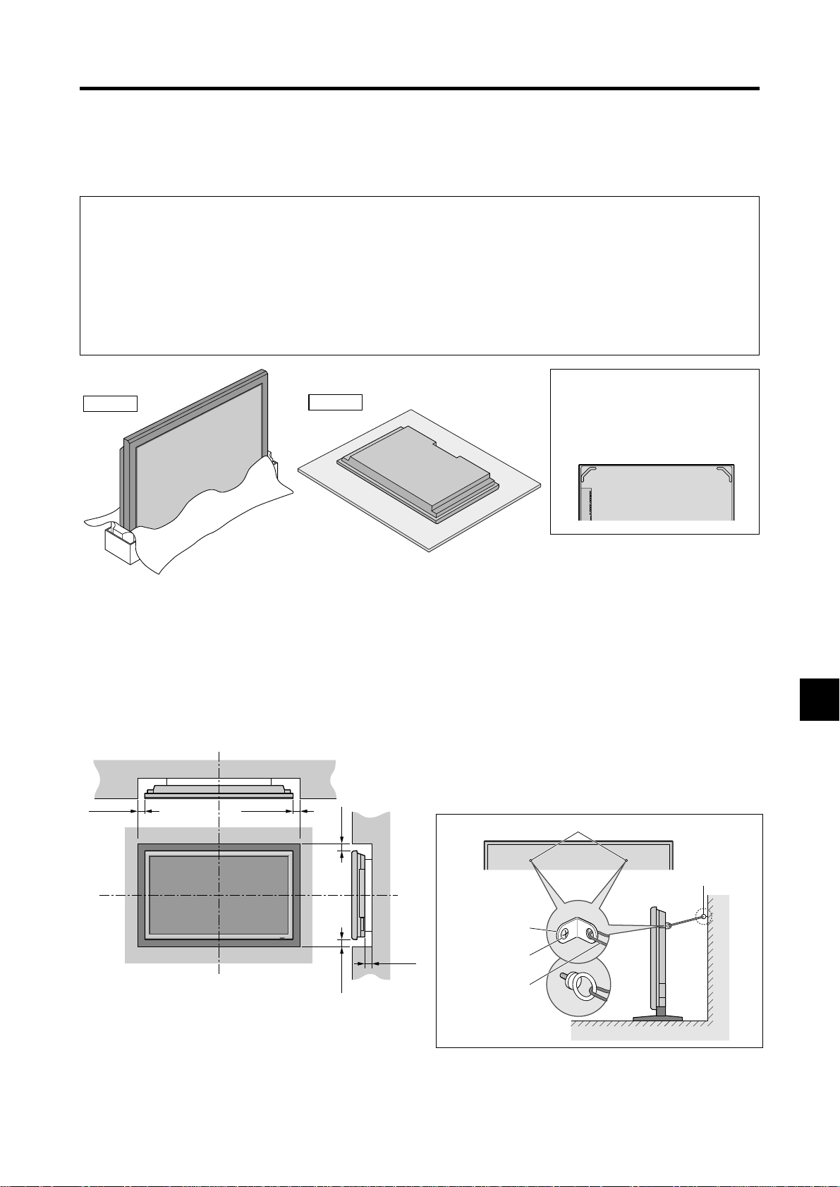
How to Attach Options to the Plasma Monitor
You can attach your optional mounts or stand to the plasma monitor in one of the following two ways:
* While it is upright. (See Drawing A)
* As it is laid down with the screen face down (See Drawing B). Lay the protective sheet, which was wrapped around the
monitor when it was packaged, beneath the screen surface so as not to scratch the screen face.
* Do not touch or hold the screen face when carrying the unit.
• This device cannot be installed on its own. Be sure to use a stand or original mounting unit. (Wall
mount unit, Stand, etc.)
* See page E-2.
• For correct installation and mounting it is strongly recommended to use a trained, authorized
dealer.
Failure to follow correct mounting procedures could result in damage to the equipment or injury
to the installer.
Product warranty does not cover damage caused by improper installation.
Some models are equipped with
Drawing A
Drawing B
handles.
When installing or carrying, use
the handles attached to the upper
back of the display.
Ventilation Requirements for
enclosure mounting
T o allow heat to disperse, leave space between surrounding
objects as shown on the diagram below when installing.
Wall
50mm (2")
50mm (2")
(2")
mm
(2") 50
mm
50
Wall
50mm (2")
How to use the safety metal fittings
and the screws for safety metal
fittings
These are fittings for fastening the unit to a wall to prevent
tipping due to external shock when using the stand
(optional). Fasten the safety fittings to the holes in the
back of the monitor using the safety fitting mount screws.
* Safety metal fittings will differ according to the model.
Screw hole
Screw or Hook etc.
(Not supplied)
Safty metal fittings
Screw for Safty metal
fittings
Metal chain
(Not supplied)
Table Top
Wall
E-1

Introduction
Introduction to the PlasmaSync
Plasma Monitor
Marantz's plasma monitor is a seamless blend of cutting-edge
visual technology and sophisticated design. At each inch,
with a 16:9 aspect ratio, the Plasma monitor certainly makes
a big impression. However, the monitor’s sleek technoart lines blend in well with your environment. Marantz
Plasma monitor’s crisp, vivid image quality will transform
data from any graphic medium from PCs to DVD players-
into art. Marantz has made sure that a host of multimedia
resources can be easily connected and displayed as
brilliantly as intended on the plasma monitor.
The features you’ll enjoy include:
• Color Filter and black matrix
• The enhanced display in red uses a two-stage filtering
system.
• Flicker - and warp - free display provides excellent
image geometry even in screen corners
• Not affected by magnetic fields, no color drift or edge
distortion.
• VGA, SVGA, XGA, SXGA, UXGA computer signal
compatibility
• NTSC, PAL, SECAM, composite and S-Video signal
compatibility
• 480P, 1080I, 720P and HDTV signal compatibility
• PCs, VCRs, Laser Disc and DVD player source
compatibility
• AccuBlend scan conversion automatically converts
VGA, SVGA, XGA, SXGA and UXGA signals to the
panel’s native resolution.
• Advanced Mass Area Sampling Progressive Scan
method is employed.
• RGB (3*), Video (3), DVD/HD (2*), Audio input (3),
External Control input (1)
• AccuColor control system provides user selectable onscreen color temperature settings
• New Drive Technology
• Component video input terminal for DVD, 15.75kHz
B, CR )
(Y, C
• Digital broadcasting source compatibility
• OSM menu-driven on screen control system that makes
image adjustments a snap
• Seven languages (English, German, French, Italian,
Spanish, Swedish, and Chinese)
Contents of the Package
Plasma monitor
Power cord
Remote control with two AAA Batteries
Manuals
Safety metal fitting parts*
Ferrite cores, bands
Cable clamps
* Contents will differ according to the model.
* These are fittings for fastening the unit to a wall to prevent
tipping due to external shock when using the stand
(optional). Fasten the safety fittings to the holes in the back
of the monitor using the safety fitting mount screws (see
page E-1).
Options
• Wall mount unit
• Stand
* You can set the 5BNC input to be used as an RGB or
component input. When the 5BNC input is set for RGB,
there are a total of three RGB inputs; when the 5BNC input
is set for component there are a total of two DVD/HD inputs
(see page E-25).
E-2
Part Names and Function
Front View
INPUT SELECT
VOLUME
MENU/ENTER
DOWN UP LEFT/-RIGHT/+/EXIT
MENU/ENTER
7
VOLUME
DOWN UP LEFT/-RIGHT/
6
5
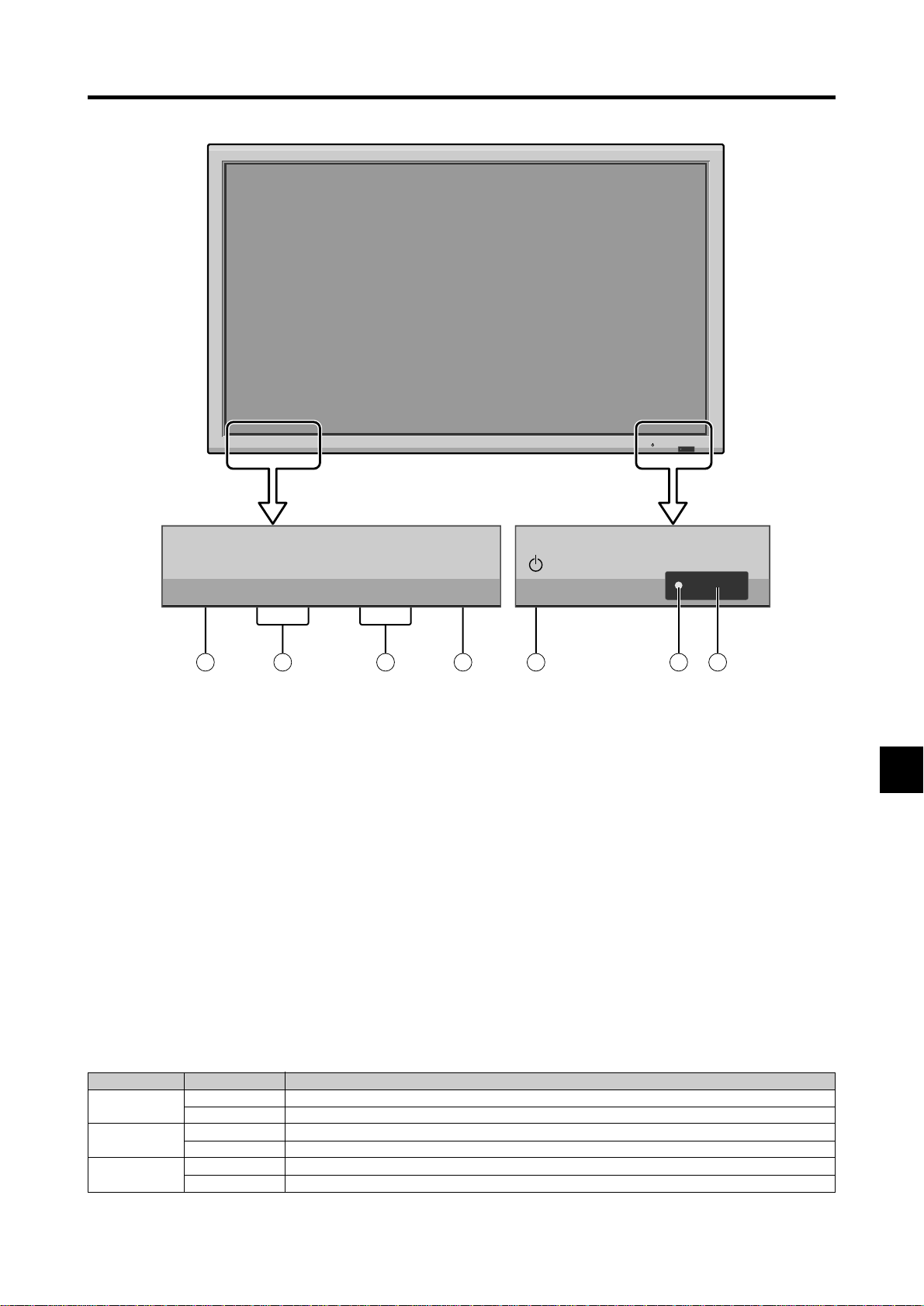
q Power
Turns the monitor’s power on and off.
w Remote sensor window
Receives the signals from the remote control.
e POWER/STANDBY indicator
When the power is on ............................. Lights green.
When the power is in the standby mode ... Lights red.
r INPUT SELECT / EXIT
Switches the input, in the order as shown in the table
below.
The available inputs depend on the settings of “BNC
INPUT” and “D-SUB INPUT”.
Functions as the EXIT buttons in the On-Screen Menu
(OSM) mode.
INPUT SELECT
+
/EXIT
4
1
t LEFT/– and RIGHT/+
Enlarges or reduces the image. Functions as the
CURSOR (
/ ) buttons in the On-Screen Menu
(OSM) mode.
y VOLUME DOWN and UP
Adjusts the volume. Functions as the CURSOR (▲/
▼) buttons in the On-Screen Menu (OSM) mode.
u MENU/ENTER
Sets the On-Screen Menu (OSM) mode and displays
the main menu.
2
3
BNC INPUT
RGB
COMP.
SCART1, 2
D-SUB INPUT
RGB
SCART3
RGB
SCART3
RGB
SCART3
Input Source
VIDEO1 → VIDEO2 → VIDEO3 → HD/DVD1 → RGB/PC1 → RGB/PC2 → RGB/PC3
VIDEO1 → VIDEO2 → VIDEO3 → HD/DVD1 → DVD3 → RGB/PC2 → RGB/PC3
VIDEO1 → VIDEO2 → VIDEO3 → HD/DVD1 → HD/DVD2 → RGB/PC1 → RGB/PC3
VIDEO1 → VIDEO2 → VIDEO3 → HD/DVD1 → HD/DVD2 → DVD3 → RGB/PC3
VIDEO1 → VIDEO2 → VIDEO3 → HD/DVD1 → DVD2 → RGB/PC1 → RGB/PC3
VIDEO1 → VIDEO2 → VIDEO3 → HD/DVD1 → DVD2 → DVD3 → RGB/PC3
E-3
Rear View/ Terminal Board
VIDEO
VIDEO
(
IN/OUT
1
)
VIDEO
VIDEO
C
E
F
G
H
I
J
3
(
MONO
)
(
MONO
)
(
MONO
)
L
L
L
External Control
REMOTE
YCb/PbCr/Pr
Cr/Pr Y Cb/Pb
HD
VD
(
IN/OUT
)
DVI
(
Digital RGB
)
IN OUT
2
AUDIO
R
1
DVD
1
/
HD
1
AUDIO
R
2
R/
G/ B/
RGB
2
/
DVD
2
/
HD
2
RGB
1
AUDIO
R
3
RGB
3
D
K
AB
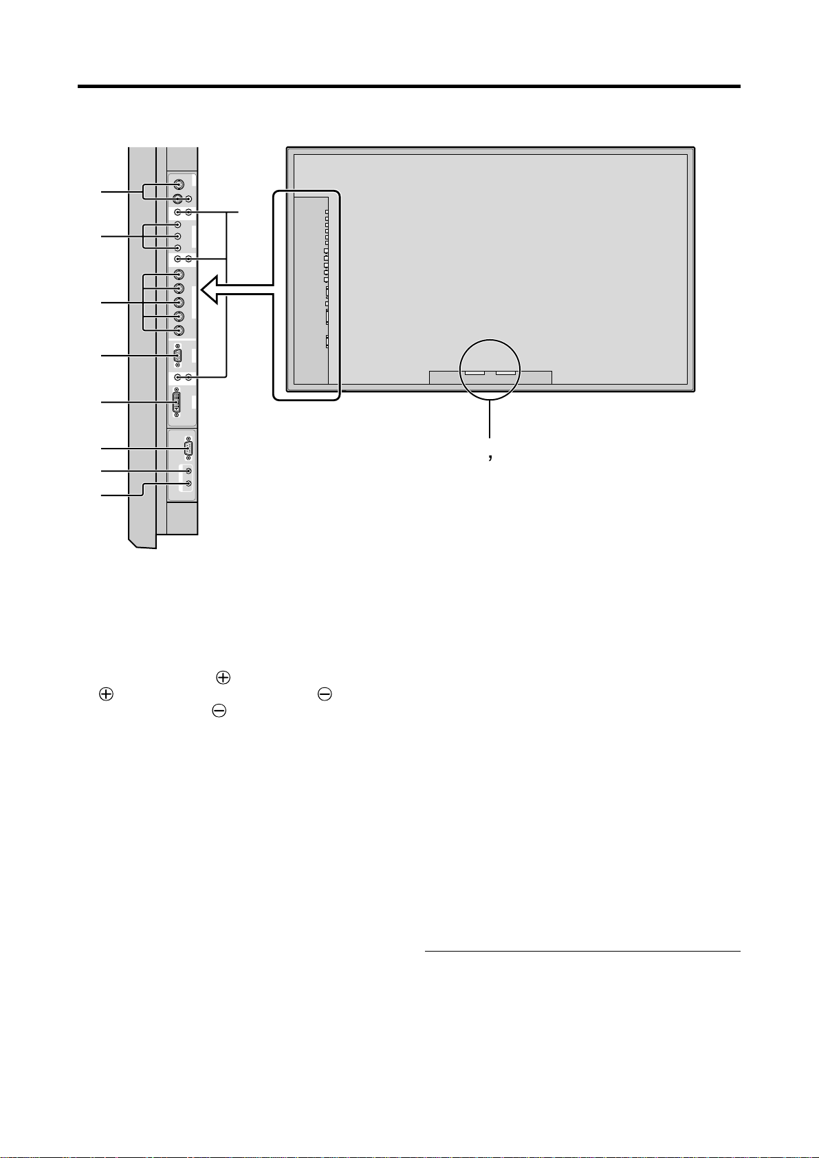
A AC IN
Connect the included power cord here.
B EXT SPEAKER L and R
Connect speakers (optional) here. Maintain the correct
polarity. Connect the
(positive) speaker wire to the
EXT SPEAKER terminal and the (negative)
speaker wire to the
EXT SPEAKER terminal on
both LEFT and RIGHT channels.
Please refer to your speaker’s owner’s manual.
C VIDEO1, 2, 3 (BNC, RCA, S-Video)
Connect VCR’s, DVD’s or Video Cameras, etc. here.
VIDEO1 can be used for Input or Output (see page E-
11).
D AUDIO1, AUDIO2, AUDIO3
These are audio input terminals.
The input is selectable. Set which video image to allot
them from the audio menu screen.
E DVD1 / HD1
Connect DVD’s, High Definition or Laser Discs, etc.
here.
F RGB2/ DVD2/ HD2
RGB2: Y ou can connect an analog RGB signal
and the syncronization signal.
DVD2/ HD2: You can connect DVDs, High
Definition sources, Laser Discs, etc.
here.
This input can be set for use with an
RGB or component source. (see page
E-25)
G RGB1 (mini D-Sub 15pin)
Connect an analog RGB signal from a computer, etc.
here. This input can be used for Input or Output. (see
page E-11)
H RGB3
(DVI 24pin)
Connect a digital signal (TMDS) from a source with a
DVI output. (see page E-9)
I EXTERNAL CONTROL
This terminal is used when operating and controlling
the monitor externally (by RS-232C).
J REMOTE IN
Connect the remote cable* to the remote control’s
remote jack to obtain wired remote control.
K REMOTE OUT
Connect the remote cable* to the REMOTE IN jack of
the other display monitor to obtain wired remote
control.
* The 1/8 Stereo Mini cable must be purchased separately.
E-4
Remote Control
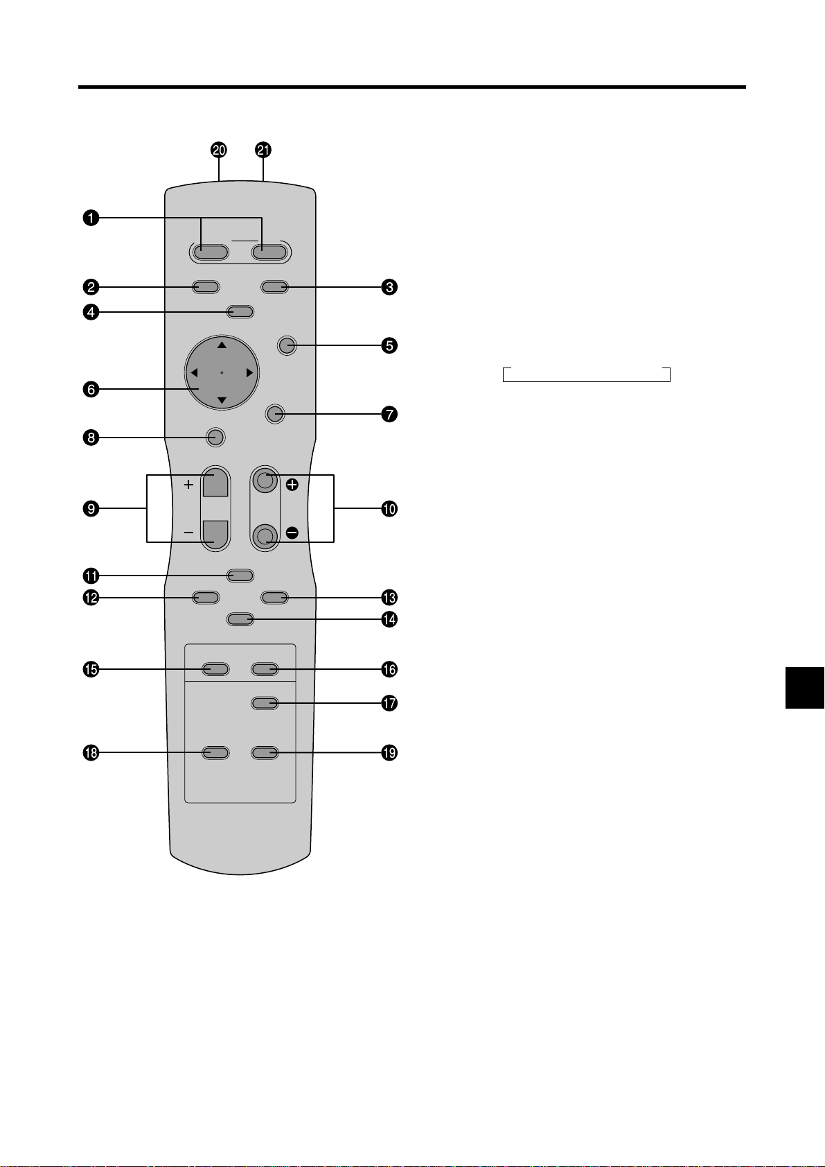
w RGB/PC
Press this button to select RGB/PC as the source.
The available sources depend on the settings of “BNC
INPUT” and “D-SUB INPUT”. See page E-3.
RGB/PC can also be selected using the INPUT
SELECT button on the monitor.
POWER
STANDBY
RGB/PC DVD/HD
VIDEO
POSITION
/ CONTROL
POINTER
ZOOM
MUTE
WIDE DISPLAY
OFF TIMER
MULTI SELECT
AUTO ADJUST
ID SELECT CLEAR
ON
MENU/ENTER
EXIT
VOLUME
e DVD / HD
Press this button to select DVD/HD as the source.
The available sources depend on the settings of “BNC
INPUT” and “D-SUB INPUT”. See page E-3.
DVD/HD can also be selected using the INPUT
SELECT button on the monitor.
r VIDEO
Press this button to select VIDEO as the source.
→ VIDEO1 → VIDEO2 → VIDEO3
VIDEO can also be selected using the INPUT SELECT
button on the monitor.
t MENU/ENTER
Press this button to access the OSM controls.
Press this button during the display of the main menu
to go to the sub menu.
y CURSOR (▲ / ▼ /
/ )
Use these buttons to select items or settings and to
adjust settings or switch the display patterns.
u EXIT
Press this button to exit the OSM controls in the main
menu. Press this button during the display of the sub
menu to return to the previous menu.
i POINTER
Press this button to display the pointer.
o ZOOM (+ /–)
Enlarges or reduces the image.
!0 VOLUME (+ /–)
Adjusts the audio volume.
q POWER ON/STANDBY
Switches the power on/standby.
(This does not operate when POWER/STANDBY
indicator of the main unit is off.)
!1 MUTE
Mutes the sound.
!2 WIDE
Automatically detects the signal and sets the aspect
ratio.
Wide button is not active for all signals.
!3 DISPLAY
Displays the source settings on the screen.
!4 OFF TIMER
Activates the off timer for the unit.
!5 MULTI
Not functional for the models covered in this manual.
!6 SELECT
Not functional for the models covered in this manual.
E-5
!7 AUTO ADJUST
Press this button to adjust Fine Picture, Picture ADJ,
Position, and Contrast automatically, or to switch the
screen size to ZOOM mode automatically with the
superimposed caption displayed fully only when the
picture contains dark areas above and below the picture.
!8 ID SELECT
Set the ID number in the remote control. The remote
control can then be used only for a display with the
same ID number. When several displays are used
together they can be controlled individually.
!9 CLEAR
Clears the number set by the ID SELECT button.
@0 Remote control signal transmitter
Transmits the remote control signals.
@1 Remote Jack
Insert the plug of the remote cable (The 1/8 Stereo
Mini cable) here when using the supplied remote
control in the wired condition.
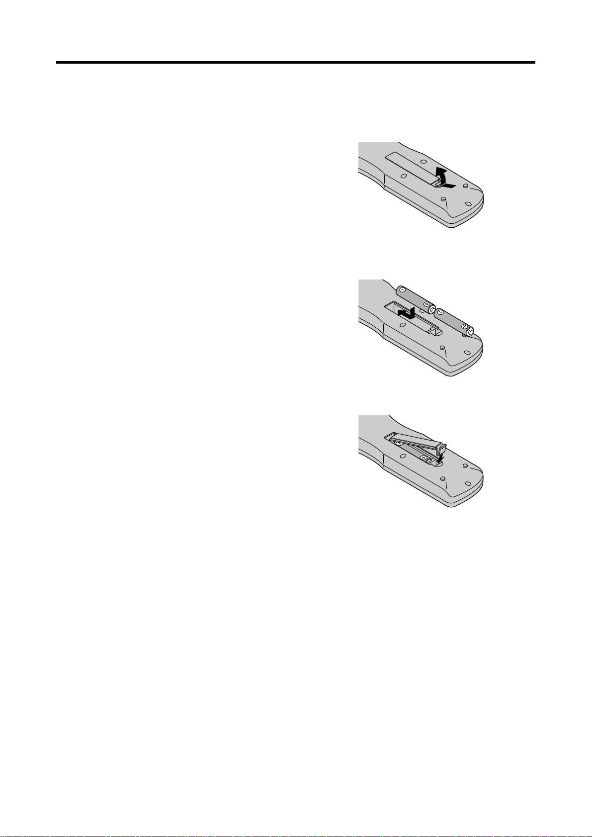
Battery Installation and Replacement
Insert the 2 “AAA” batteries, making sure to set them in
with the proper polarity.
1.Press and open the cover.
2.Align the batteries according to the (+) and (–) indication
inside the case.
3.Replace the cover.
E-6
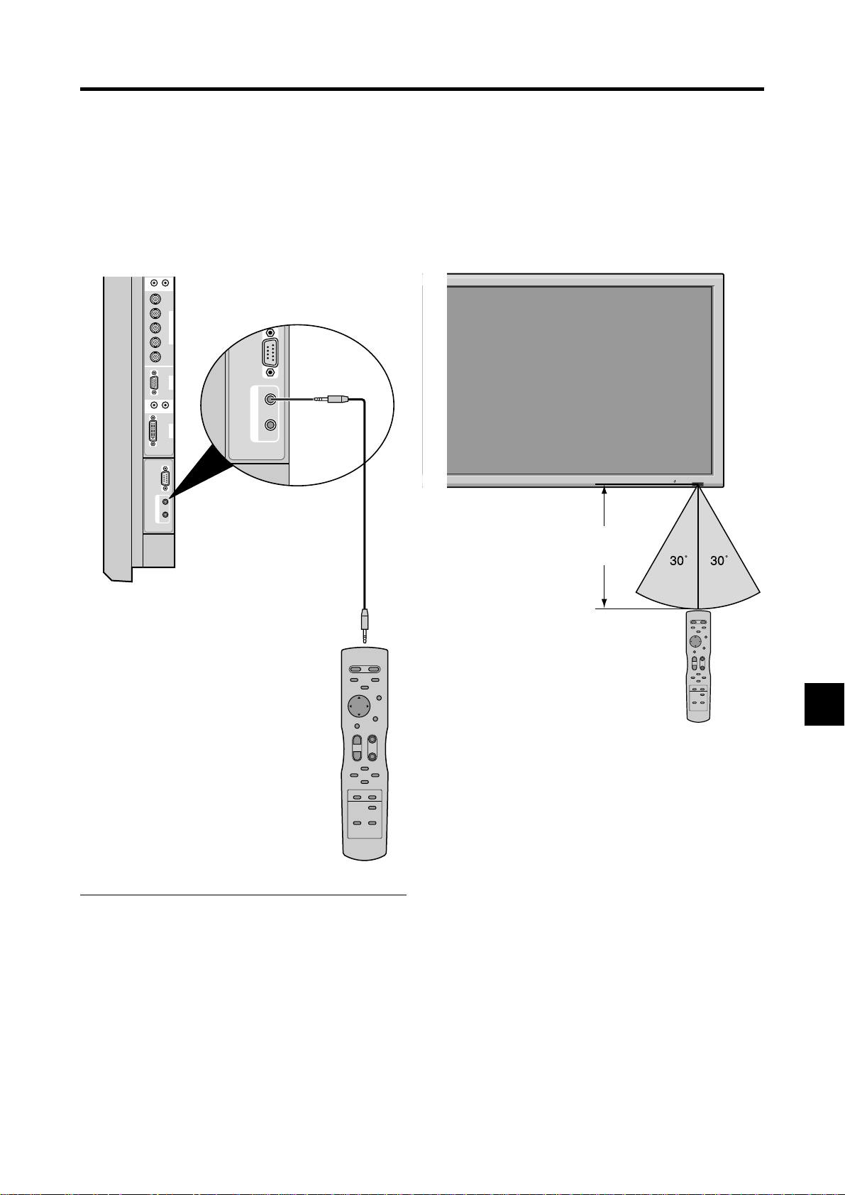
Using the wired remote control mode
External Control
IN OUT
REMOTE
Connect the remote cable* to the remote control’s remote
jack and the “REMOTE IN” terminal on the monitor.
When the cable is connected, the mode automatically
switches to wired remote control. When the wired remote
control mode is used, the remote control can be operated
even if no batteries are loaded.
AUDIO
(
MONO
)
R
L
2
Cr/Pr Y Cb/Pb
R/
G/ B/
RGB
2
/
DVD
2
/
HD
2
HD
VD
(
IN/ OUT
RGB
1
)
AUDIO
(
MONO
)
R
L
3
DVI
(
RGB
Digital RGB
3
)
External Control
IN OUT
REMOTE
Operating Range
* Use the remote control within a distance of about 7 m/
23ft. from the front of the monitor’s remote control sensor
and at horizontal and vertical angles of up to approximately
30°.
* The remote control operation may not function if the
monitor’s remote control sensor is exposed to direct
sunlight or strong artificial light, or if there is an obstacle
between the sensor and the remote control.
POWER/STANDBY
Remote Control
Cable*
To Remote Jack
* The 1/8 Stereo Mini cable must be purchased separately.
Approx.
7m/23ft
Handling the remote control
• Do not drop or mishandle the remote control.
• Do not get the remote control wet. If the remote control
gets wet, wipe it dry immediately.
• Avoid heat and humidity.
• When not using the remote control for a long period,
remove the batteries.
• Do not use new and old batteries together, or use different
types together.
• Do not take apart the batteries, heat them, or throw them
into a fire.
• When using the remote control in the wireless condition,
be sure to unplug the remote cable from the REMOTE
IN terminal on the monitor.
E-7
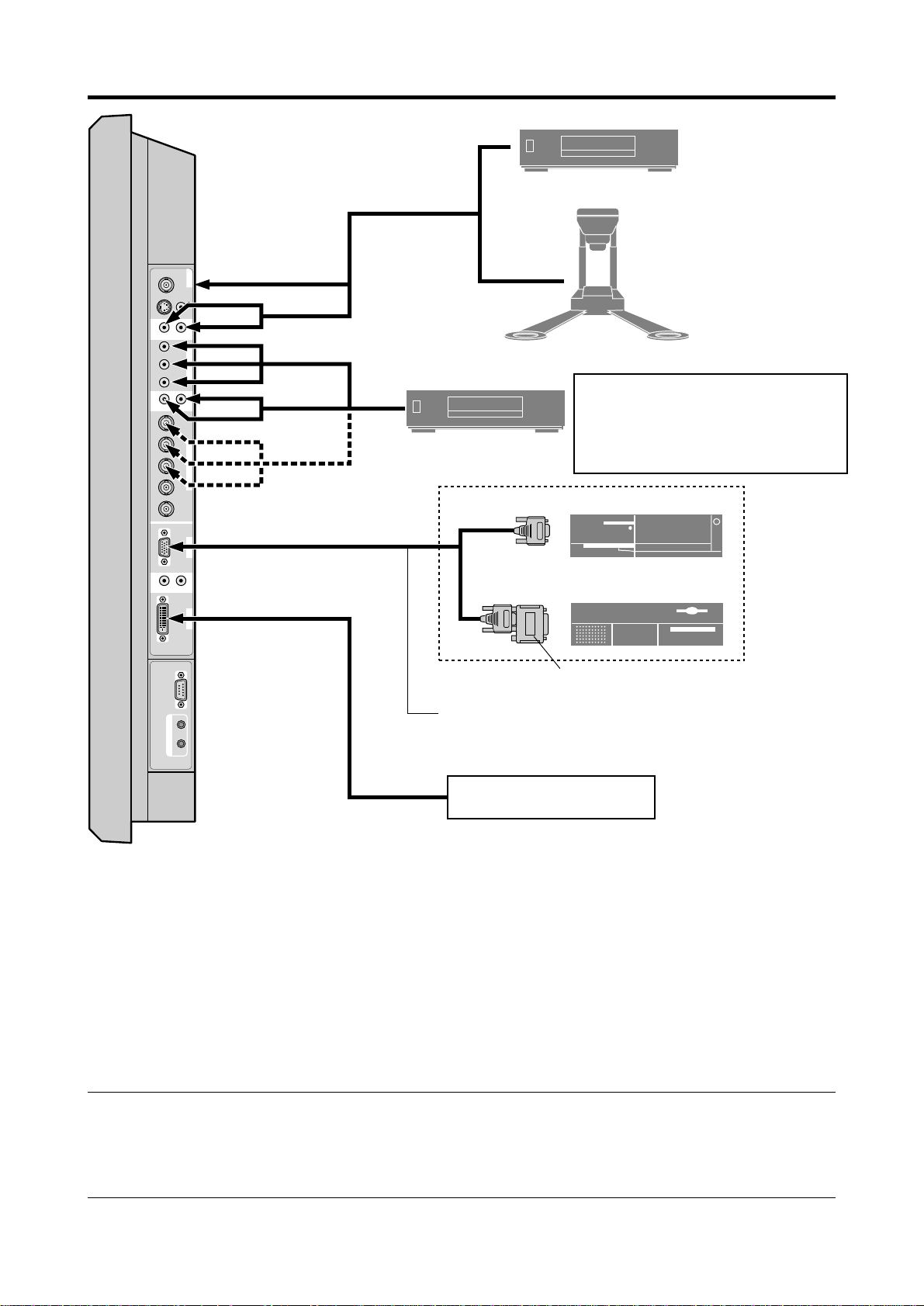
Installation
VIDEO
(
IN/OUT
)
VIDEO
1
VIDEO
2
VIDEO
3
AUDIO
1
DVD
1
/
HD
1
R
(
MONO
)
L
Y Cb/ Pb Cr/Pr
RGB
2
/
DVD
2
/
HD
2
RGB
1
R/
VD
G/ B/
HD
(
IN /OUT
)
DVI
(
Digital RGB
)
AUDIO
2
R
(
MONO
)
L
AUDIO
3
R
(
MONO
)
L
Cr/Pr Y Cb /Pb
RGB
3
External Control
IN OUT
REMOTE
VCR or Laser Disc Player
Document Camera
VIDEO 1-3
DVD Player
IBM VGA or
Compatibles
To Mini D-Sub 15 pin connector on the plasma monitor
To video inputs on
the plasma monitor
Monitor adapter for
Macintosh
Macintosh or Compatibles
(Desk top type)
Personal computer with a
digital signal output
• For Y/CB/Cr, connect to the DVD1 or DVD2 terminals.
• For SCART, this unit provides three ways to connect:
· SCART1...Connect R/G/B to the DVD2 terminals and
composite sync. to the HD terminal.
· SCART2...Connect R/G/B to the DVD2 terminals and
composite sync. to the VIDEO1 terminal.
· SCART3...Connect R/G/B + composite sync. to the RGB1 terminal.
Note:
output signal, which is RGB with composite sync.
This plasma monitor has the capasity to display images when connected to European DVD players with a SCART
Your dealer can supply a special SCART cable, which will enable you to use the RGB with composite sync signal.
To obtain the special cable as well as for further information, please contact your dealer.
Please refer to page E-25 for selection of the correct mode in the on-screen manager.
E-8

Connecting Your PC or Macintosh Computer
Connecting your PC or Macintosh computer to your plasma
monitor will enable you to display your computer’s screen
image for an impressive presentation. The plasma monitor
supports the signals described on page E-3 of Model
Information.
T o connect a PC, Macintosh or compatible graphics adapter,
simply:
1. Turn off the power to your plasma monitor and computer .
Connecting Your Document Camera
You can connect your plasma monitor to a document
camera. To do so, simply:
1. Turn off the power to your plasma monitor and
document camera.
2. Use a standard video cable to connect your document
camera to the Video input on your plasma monitor.
3. Turn on the plasma monitor and the document camera.
2. If your PC does not support SXGA/XGA/SVGA/VGA
you will need to install an SXGA/XGA/SVGA/VGA
graphics board. Consult your computer’s owner’s manual
for your SXGA/XGA/SVGA/VGA configuration. If you
need to install a new board, see the manual that comes
with your new graphics board for installation instructions.
3. This plasma monitor provides signal compatibility up to
VESA 16001200 (UXGA). However, it is not
recommended to use this resolution due to image
readability on the monitor’s native pixel resolution panel.
4. Use the signal cable to connect your PC or Macintosh
computer to the plasma monitor. For Macintosh, use the
monitor adapter to connect to your computer’s video port,
if necessary.
5. Turn on the plasma monitor and the computer.
6. If the plasma monitor goes blank after a period of inactivity,
it may be caused by a screen saver installed on the computer
you’ve connected to the plasma monitor .
When using a Macintosh with the plasma monitor, the
following four display standards are supported using the
Macintosh adapter :
13" fixed mode
16" fixed mode
19" fixed mode
21" fixed mode
The 19" fixed mode is recommended for your monitor.
Note:
for more information about your camera’s video output
requir ements.
Refer to your document camera owner’ s manual
Connecting Your VCR or Laser Disc
Player
Use common RCA cables (not provided) to connect your
VCR or laser disc player to your plasma monitor. T o make
these connections, simply:
1. Turn off the power to your plasma monitor and VCR
or laser disc player.
2. Connect one end of your RCA cable to the video output
connector on the back of your VCR or laser disc player,
connect the other end to the V ideo input on your plasma
monitor. Use standard RCA audio patch cords to
connect the audio from your VCR or laser disc player
to your plasma monitor (if your VCR or laser disc player
has this capability). Be careful to keep your right and
left channel connections correct for stereo sound.
3. Turn on the plasma monitor and the VCR or laser disc
player.
Note:
manual for more information about your equipment’s video
output requir ements.
Refer to your VCR or laser disc player owner’s
Connections with Equipment that
have a Digital Interface
Connections can be made with equipment that is equipped
with a digital interface compliant with the DVI (Digital
Visual Interface) standard.
* Use a DVI 24-pin signal cable and the ferrite cores
(supplied) when making connections to the RGB3 (DVI)
connector of the main unit.
Note that the RGB3 (DVI) terminal does not support analog
RGB input source.
Note:
1. Input TMDS signals conforming to DVI standards.
The TMDS input corresponds to 1 link.
2. To maintain display quality, use a cable with a quality
prescribed by DVI standar ds that is within 5 meters in length.
Connecting Your DVD Player
You can connect your plasma monitor to a DVD player.
To do so, simply:
1. Turn off the power to your plasma monitor and DVD
player.
2. Use a component video cable to connect your DVD
player to the Y, Cb, and Cr inputs on your plasma
monitor.
Or use the DVD-player’s S-Video output. Use a
standard S-Video cable to connect to the S-Video input
on the plasma monitor.
3. Turn on the plasma monitor and the DVD player.
E-9
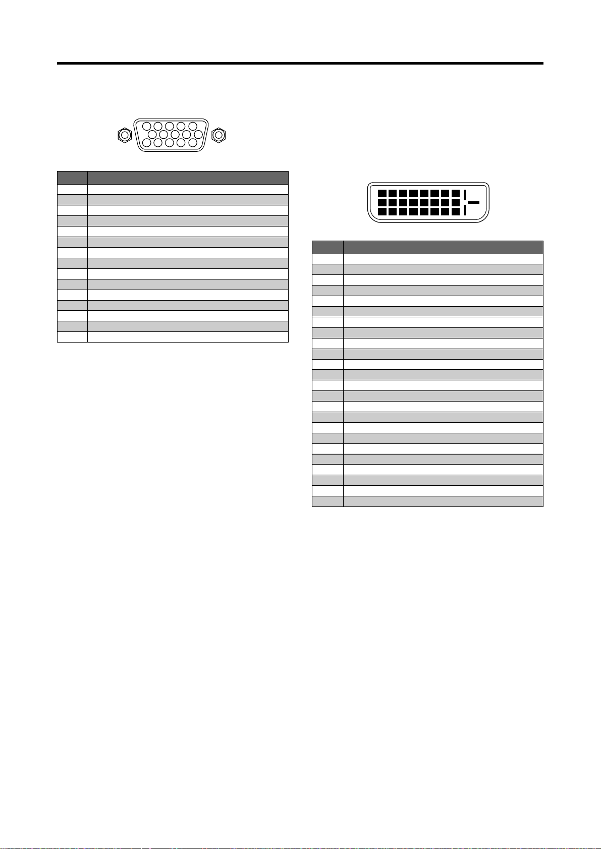
Pin Assignments and Signal Levels
for 15 pin RGB (Analog)
5 4 3 2 1
10 9 8 7 6
15 14 13 12 11
Pin Configuration and Signal of the
RGB 3 Connector (DVI Connector)
The unit is equipped with a type of connector commonly
used for digital.
(This cannot be used for an analog input.)
(TMDS can be used for one link only.)
Pin No.
1
2
3
4
5
6
7
8
9
10
11
12
13
14
15
Signal (Analog)
Red
Green or sync-on-green
Blue
No connection
Ground
Red ground
Green ground
Blue ground
No connection
Sync signal ground
No connection
Bi-directional DATA (SDA)
Horizontal sync or Composite sync
Vertical sync
Data clock
Pin No.
1
2
3
4
5
6
7
8
9
10
11
12
13
14
15
16
17
18
19
20
21
22
23
24
RGB 3
12345678
910111213141516
20191817 21 22 23 24
Signal (Digital)
T.M.D.S Data 2 T.M.D.S Data 2 +
T.M.D.S Data 2 Shield
No connection
No connection
DDC Clock
DDC Data
No connection
T.M.D.S Data 1 T.M.D.S Data 1 +
T.M.D.S Data 1 Shield
No connection
No connection
+5V Power
Ground
Hot Plug Detect
T.M.D.S Data 0 T.M.D.S Data 0 +
T.M.D.S Data 0 Shield
No connection
No connection
T.M.D.S Clock Shield
T.M.D.S Clock +
T.M.D.S Clock -
E-10
 Loading...