


NR1402
Table of contents
 Loading...
Owner’s Manual
AV Surround Receiver
NR1402
Basic version
Advanced version
Information
I
n
SAFETY PRECAUTIONS
CAUTION
RISK OF ELECTRIC SHOCK
DO NOT OPEN
CAUTION:
TO REDUCE THE RISK OF ELECTRIC SHOCK, DO NOT REMOVE
COVER (OR BACK). NO USER-SERVICEABLE PARTS INSIDE.
REFER SERVICING TO QUALIFIED SERVICE PERSONNEL.
The lightning flash with arrowhead symbol, within an equilateral
triangle, is intended to alert the user to the presence of
uninsulated “dangerous voltage” within the product’s enclosure
that may be of sufficient magnitude to constitute a risk of
electric shock to persons.
The exclamation point within an equilateral triangle is intended
to alert the user to the presence of important operating
and maintenance (servicing) instructions in the literature
accompanying the appliance.
WARNING:
TO REDUCE THE RISK OF FIRE OR ELECTRIC SHOCK, DO NOT
EXPOSE THIS APPLIANCE TO RAIN OR MOISTURE.
CAUTION:
To completely disconnect this product from the mains, disconnect the plug
from the wall socket outlet.
The mains plug is used to completely interrupt the power supply to the unit
and must be within easy access by the user.
IMPORTANT SAFETY
INSTRUCTIONS
1. Read these instructions.
2. Keep these instructions.
3. Heed all warnings.
4. Follow all instructions.
5. Do not use this apparatus near water.
6. Clean only with dry cloth.
7. Do not block any ventilation openings.
Install in accordance with the manufacturer’s instructions.
8. Do not install near any heat sources such as radiators, heat registers,
stoves, or other apparatus (including amplifiers) that produce heat.
9. Protect the power cord from being walked on or pinched particularly at
plugs, convenience receptacles, and the point where they exit from the
apparatus.
10. Only use attachments/accessories specified by the manufacturer.
11. Use only with the cart, stand, tripod, bracket, or table
specified by the manufacturer, or sold with the apparatus.
When a cart is used, use caution when moving the cart/
apparatus combination to avoid injury from tip-over.
12. Unplug this apparatus during lightning storms or when
unused for long periods of time.
13. Refer all servicing to qualified service personnel.
Servicing is required when the apparatus has been damaged in any way,
such as power-supply cord or plug is damaged, liquid has been spilled or
objects have fallen into the apparatus, the apparatus has been exposed to
rain or moisture, does not operate normally, or has been dropped.
14. Batteries shall not be exposed to excessive heat such as sunshine, fire or
the like.
• DECLARATION OF CONFORMITY
We declare under our sole responsibility that this product, to which this
declaration relates, is in conformity with the following standards:
EN60065, EN55013, EN55020, EN61000-3-2 and EN61000-3-3.
Following the provisions of Low Voltage Directive 2006/95/EC and EMC
Directive 2004/108/EC, the EC regulation 1275/2008 and its frame work
Directive 2009/125/EC for Energy-related Products (ErP).
marantz Europe
A division of D&M Europe B.V.
Beemdstraat 11, 5653 MA Eindhoven,
The Netherlands
A NOTE ABOUT RECYCLING:
This product’s packaging materials are recyclable and can
be reused. Please dispose of any materials in accordance
with the local recycling regulations.
When discarding the unit, comply with local rules or
regulations.
Batteries should never be thrown away or incinerated
but disposed of in accordance with the local regulations
concerning battery disposal.
This product and the supplied accessories, excluding the
batteries, constitute the applicable product according to
the WEEE directive.
Basic version
Advanced version
Information
II
n
NOTES ON USE
WARNINGS
•Avoid high temperatures.
Allow for sufficient heat dispersion when installed in a rack.
•Handle the power cord carefully.
Hold the plug when unplugging the cord.
•Keep the unit free from moisture, water, and dust.
•Unplug the power cord when not using the unit for long periods of time.
•Do not obstruct the ventilation holes.
•Do not let foreign objects into the unit.
•Do not let insecticides, benzene, and thinner come in contact with the unit.
•Never disassemble or modify the unit in any way.
•Ventilation should not be impeded by covering the ventilation openings
with items, such as newspapers, tablecloths or curtains.
•Naked flame sources such as lighted candles should not be placed on
the unit.
•Observe and follow local regulations regarding battery disposal.
•Do not expose the unit to dripping or splashing fluids.
•Do not place objects filled with liquids, such as vases, on the unit.
•Do not handle the mains cord with wet hands.
•When the switch is in the OFF (STANDBY) position, the equipment is not
completely switched off from MAINS.
•The equipment shall be installed near the power supply so that the power
supply is easily accessible.
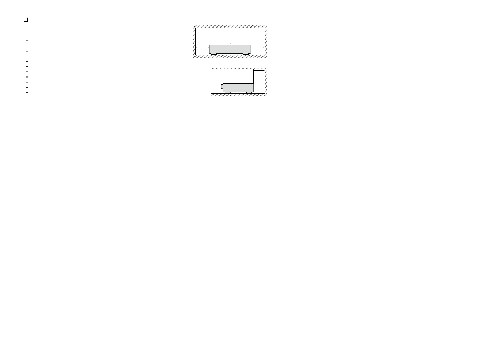
n CAUTIONS ON INSTALLATION
z z
z
Wall
z
z For proper heat dispersal, do not install this unit in a confined
space, such as a bookcase or similar enclosure.
•More than 0.3 m is recommended.
•Do not place any other equipment on this unit.
Basic version
Advanced version
Information
1
Thank you for purchasing this marantz product. To ensure proper operation, please read this owner’s manual carefully before using the product.
After reading them, be sure to keep them for future reference.
Getting started
Basic version ············································································3
Connections ··················································································· 4
Important information ··································································· 4
Connecting an HDMI-compatible device ······································ 5
Connecting a TV············································································7
Connecting a Blu-ray Disc player/DVD player ······························· 7
Connecting a set-top box (Satellite tuner/Cable TV) ·····················8
Connecting a portable audio player ···············································8
Connecting a CD player ································································ 9
Connecting an antenna ································································· 9
Connecting a wireless receiver (RX101) ····································· 10
Settings ························································································ 11
Set up speakers (Audyssey® Auto Setup) ·································11
Playback (Basic operation) ························································· 18
Important information ································································· 18
Playing a Blu-ray Disc player/DVD player ···································· 19
Playing a CD player ····································································· 19
Tuning in radio stations ······························································· 20
Selecting a listening mode (Surround mode) ··························24
Selecting a listening mode··························································24
Advanced version ·······························································28
Speaker installation/connection (Advanced) ·························· 29
Install ··························································································29
Connect ······················································································31
Set up speakers ·········································································· 35
Connections (Advanced connection)·········································37
Connecting the remote control connectors ································ 37
Playback (Advanced operation) ················································· 38
Convenient functions ·································································· 38
How to make detailed settings ·················································· 43
Menu map ··················································································43
Examples of menu screen displays ············································ 44
Examples of menu and front display ··········································45
Inputting characters ··································································· 46
Audio Adjust ···············································································48
Information ·················································································53
System Setup ············································································· 54
Input Setup ················································································· 62
Other settings ·············································································· 67
Remote control settings ····························································· 67
Operating the connected devices by remote control unit ······68
Operating AV devices ································································· 68
Registering preset codes ···························································· 69
Operating devices ······································································· 71
Information ·············································································73
Part names and functions···························································74
Front panel ·················································································· 74
Display ························································································ 75
Rear panel ··················································································· 76
Remote control unit ···································································· 77
Other information ·······································································79
Trademark information ································································79
Surround ····················································································· 80
Relationship between video signals and monitor output ············ 84
Explanation of terms ··································································· 85
Troubleshooting ·········································································· 87
Resetting the microprocessor ····················································89
Specifications ··············································································90
Getting started ·············································································· 1
Accessories ··················································································1
Features ························································································ 2
Cautions on handling ····································································2
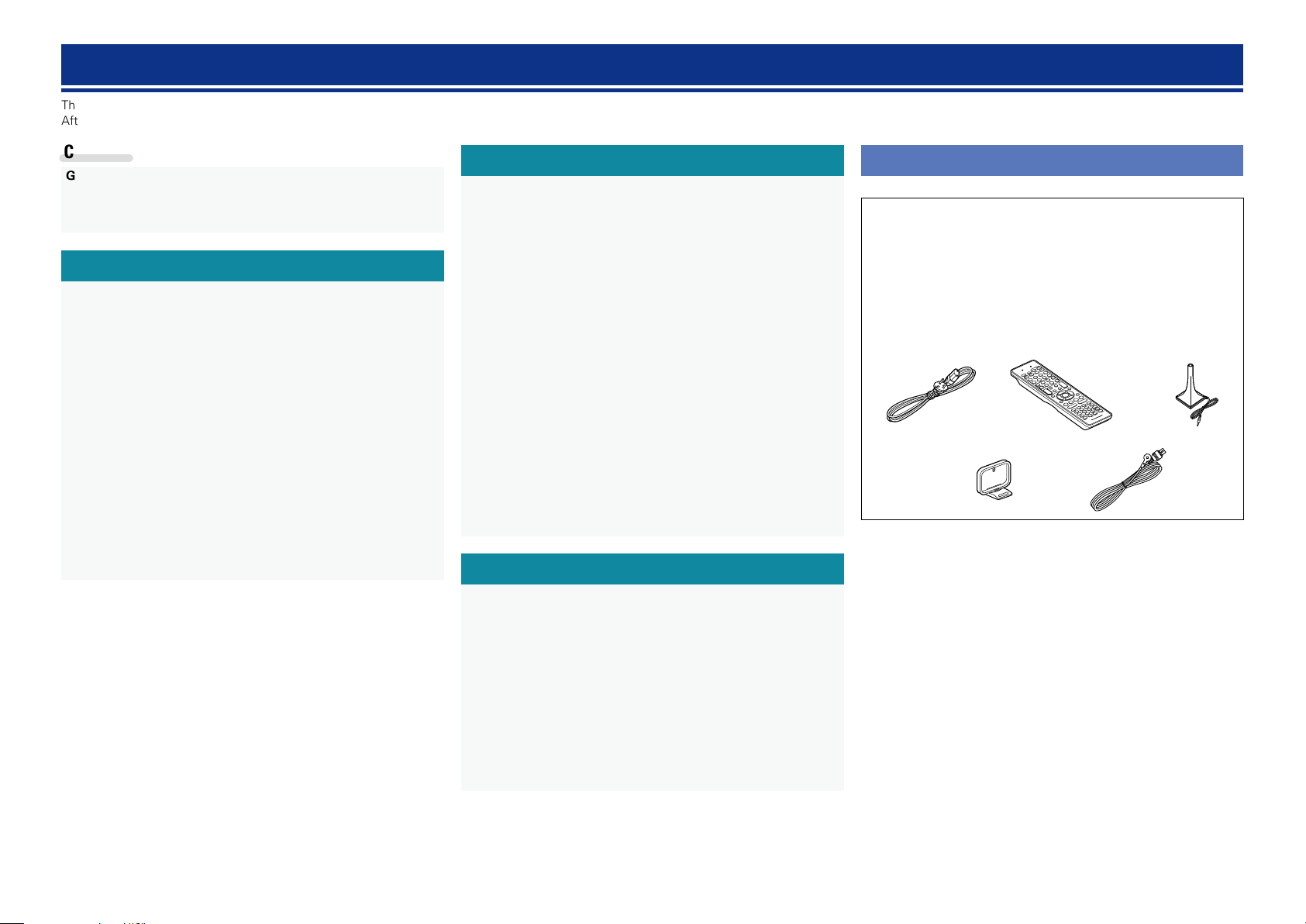
Accessories
Check that the following parts are supplied with the product.
q Getting Started ........................................................................ 1
w CD-ROM (Owner’s manual) .................................................... 1
e Power cord .............................................................................. 1
r Remote control unit (RC013SR) .............................................. 1
t R03/AAA batteries ................................................................... 2
y Setup microphone (ACM1H) ................................................... 1
u AM loop antenna ..................................................................... 1
i FM indoor antenna .................................................................. 1
re
u i
y
Contents
Basic version
Advanced version
Information

2
Features
Fully discrete, identical quality and power for all
5 channels (50 W x 5ch, 8 Ω)
The unit is equipped with a power amplifier that reproduces high-
fidelity sound in surround mode with equal quality and power for all
channels, true to the original sound.
The power amplifier circuit adopts a discrete-circuit configuration
that achieves high-quality surround sound reproduction.
Setup wizard, providing easy-to-follow setup
instructions
First select the language when prompted. Then simply follow the
instructions displayed on the TV screen to set up the speakers, etc.
Easy to use, Graphical User Interface
This unit is equipped with an easy to see “Graphical User Interface”
that uses menu displays and levels. The use of level displays
increases operability of the this unit.
Supports HDMI 1.4a with 3D, ARC, Deep Color,
“x.v.Color”, Auto Lip Sync and HDMI control
function (vpage5)
This unit can output 3D video signals input from a Blu-ray Disc
player to a TV that supports a 3D system. This unit also supports
the ARC (Audio Return Channel) function, which reproduces TV
sound with this unit via an HDMI cable used for connecting the
unit and a TV
z
.
z The TV should support the ARC function.
4-HDMI inputs and 1-output
The unit is equipped with 4 HDMI input connectors for connecting
devices with HDMI connectors, such as a Blu-ray Disc player,
game machine, HD video camera, etc.
High definition audio support
The unit is equipped with a decoder which supports high-quality
digital audio format for Blu-ray Disc players such as Dolby TrueHD,
DTS-HD Master Audio, etc.
M-XPort (marantz-eXtension Port) (vpage10)
This unit is equipped with the M-XPort, a marantz original innovation
that provides outstanding expandability. You can connect the
Wireless Receiver RX101 (sold separately) to this port.
Cautions on handling
•Before turning the power on
Check once again that all connections are correct and that there are
no problems with the connection cables.
•Power is supplied to some of the circuitry even when the unit is
set to the standby mode. When going on vacation or leaving home
for long periods of time, be sure to unplug the power cord from the
power outlet.
•About condensation
If there is a major difference in temperature between the inside of
the unit and the surroundings, condensation (dew) may form on
the operating parts inside the unit, causing the unit not to operate
properly.
If this happens, let the unit sit for an hour or two with the power
turned off and wait until there is little difference in temperature
before using the unit.
•Cautions on using mobile phones
Using a mobile phone near this unit may result in noise. If that
occurs, move the mobile phone away from this unit when it is in use.
•Moving the unit
Turn off the power and unplug the power cord from the power
outlet. Next, disconnect the connection cables to other system units
before moving the unit.
•About care
•Wipe the cabinet and control panel clean with a soft cloth.
•Follow the instructions when using a chemical cleaner.
•Benzene, paint thinner or other organic solvents as well as
insecticide may cause material changes and discoloration if brought
into contact with the unit, and should therefore not be used.
Basic version
Advanced version
Information
Basic
version
3
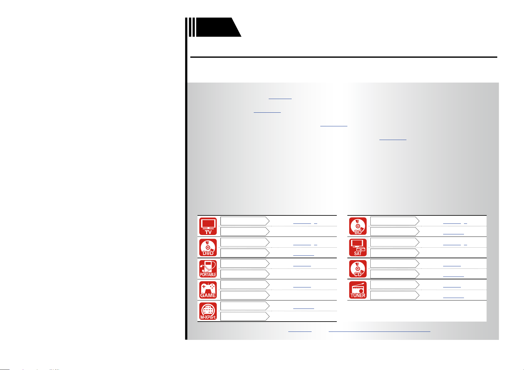
F Connections vpage4
F Settings vpage11
F Playback (Basic operation) vpage18
F Selecting a listening mode (Surround mode) vpage24
Connection
vpage6, 7
Connection
vpage6, 7
Playback
–
Playback
vpage19
Connection
vpage6, 7
Connection
vpage6, 8
Playback
vpage19
Playback
–
Connection
vpage8
Connection
vpage9
Playback
–
Playback
vpage19
Connection
vpage6
Connection
vpage9
Playback
–
Playback
vpage20
Connection
vpage10
Playback
–
For speaker connections, see page31, C page 6 “Connecting the speakers”.
Basic version
Here, we explain the connections and basic operation methods for this unit.
Basic version
Advanced version
Information
Basic version
4
Important information
•Make connections as follows before using this unit. Select an appropriate connection type
according to the devices to be connected.
•You may need to make some settings on this unit depending on the connection method. Refer to
each description for more information.
•Select the cables (sold separately) according to the devices being connected.
NOTE
•Do not plug in the power cord until all connections have been completed. (When the Setup wizard is
running, follow the instructions in the Setup wizard screen for making connections.)
•When running the Setup wizard, turn off the power supply of connected devices.
•When making connections, also refer to the operating instructions of the other devices being connected.
•Be sure to connect the left and right channels properly (left with left, right with right).
•Do not bundle power cords together with connection cables. Doing so can result in noise.
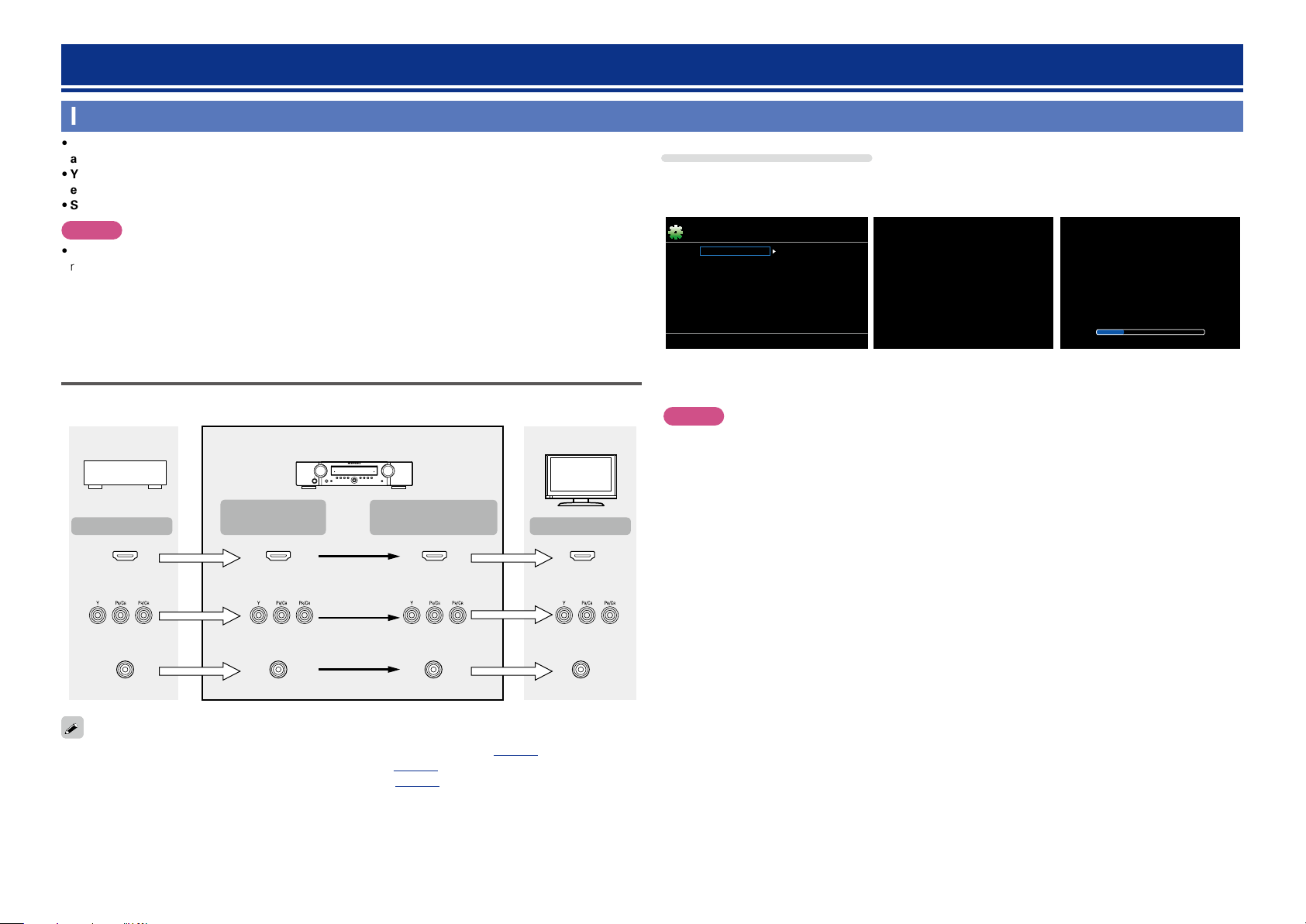
Relationship between video signals and monitor output
GFlow of video signalsH
HDMI connector
Component video
connectors
Video connector
Monitor (TV)
HDMI connector
Component video
connectors
Video connector
HDMI
connector
Video connector
HDMI connector
Video connector
Video device
This unit
Output
Input
(IN)
Output
(MONITOR OUT)
Input
Component video
connectors
Component video
connectors
•Resolutions of HDMI-compatible TVs can be checked at “Monitor Info.” (vpage53).
•HDMI signals cannot be converted into analog signals (vpage84).
•Analog signals cannot be converted into HDMI signals (vpage84).
Connections
Examples of screen display
•Menu screen •Status display screen
When the input source is
switched.
When the volume is adjusted.
Audio Adjust
Information
Setup Wizard
System Setup
Input Setup
Surr.Parameter
Tone
AudysseySettings
Manual EQ
M-DAX
Audio Delay
Menu
SOURCE :BD
MODE
:STEREO
[Auto]
Master Volume -55.5dB
Status display: The operating status appears briefly on the screen
when the input source is switched or the volume is
changed.
NOTE
•If you operate the menu while playing back 3D video content or computer’s resolution (e.g. VGA), the
playback video is replaced by the menu screen. The playback video is not displayed behind the menu
screen.
•This unit does not show the status display while playing back 3D video content or computer’s resolution
(e.g. VGA).
•The menu screen and status display are displayed when this unit and a TV are connected by HDMI.
Furthermore, the menu screen and status display are not displayed when this unit and a TV are connected
by VIDEO and COMPONENT VIDEO.
Basic version
Advanced version
Information
Basic version
5
Connecting an HDMI-compatible device
You can connect up to five HDMI-compatible devices (4-inputs/1-output) to the unit.
HDMI function
This unit supports the following HDMI functions:
•3D
•Deep Color (vpage85)
•Auto Lip Sync (vpage58, 85)
•“x.v.Color”, sYCC601 color, Adobe RGB color, Adobe YCC601 color (vpage85, 86)
•High definition digital audio format
•ARC (Audio Return Channel)
•Content Type
•CEC (HDMI control)
Copyright protection system
In order to play back digital video and audio such as BD-Video or DVD-Video via HDMI connection, both
this unit and TV or the player need to support the copyright protection system known as HDCP (High-
bandwidth Digital Content Protection System). HDCP is copyright protection technology comprised of
data encryption and authentication of the connected AV devices. This unit supports HDCP.
•If a device that does not support HDCP is connected, video and audio are not output correctly. Read
the owner’s manual of your television or player for more information.
About HDMI cables
•When a device supporting Deep Color is connected, use a cable compatible with “High Speed HDMI
cable” or “High Speed HDMI cable with Ethernet”.
•When the ARC function is used, connect a device with a ”Standard HDMI cable with Ethernet” or “High
Speed HDMI cable with Ethernet” for HDMI 1.4a.
HDMI control function (vpage38)
This function allows you to operate external devices from the unit and operate the unit from external
devices.
NOTE
•The HDMI control function may not work depending on the device it is connected to and its settings.
•You cannot operate a TV or Blu-ray Disc player/DVD player that is not compatible with the HDMI control
function.
About 3D function
This unit supports input and output of 3D (3 dimensional) video signals of HDMI 1.4a.
To play back 3D video, you need a TV and player that provide support for the HDMI 1.4a 3D function and
a pair of 3D glasses.
NOTE
•When playing back 3D video, refer to the instructions provided in the manual of your playback device
together with this manual.
•If you operate the menu while playing back 3D video content, the playback video is replaced by the menu
screen. The playback video is not displayed behind the menu screen.
•This unit does not show the status display while playing back 3D video content.
•If 3D video with no 3D information is input, the menu screen and status display on this unit are displayed
over the playback video.
•If 2D video is converted to 3D video on the television, the menu screen and status display on this unit
are not displayed correctly. To view the menu screen and status display on this unit correctly, turn the
television setting that converts 2D video to 3D video off.
About ARC (Audio Return Channel) function
The Audio Return Channel in HDMI 1.4a enables a TV, via a single HDMI cable, to send audio data “upstream”
to this unit.
NOTE
•To enable the ARC function, set “HDMI Control” to “ON” (vpage58).
•When connecting a TV that does not support the ARC function, a separate connection using an audio
cable is required. In this case, refer to “Connecting a TV” (vpage7) for the connection method.
About Content Type
HDMI 1.4a enables simple, automated picture setting selection with no user intervention.
NOTE
To enable the Content Type, set “Video Mode” to “Auto” (vpage65).
Basic version
Advanced version
Information
Basic version
vSee overleaf
6
Connecting an HDMI-compatible device
•When this unit is connected to other devices with HDMI cables, connect this unit and TV also with an
HDMI cable.
•When connecting a device that supports Deep Color, please use a “High Speed HDMI cable” or “High
Speed HDMI cable with Ethernet”.
•Video signals are not output if the input video signals do not match the monitor’s resolution. In this case,
switch the Blu-ray Disc/DVD player’s resolution to a resolution with which the monitor is compatible.
•When this unit and monitor are connected with an HDMI cable, if the monitor is not compatible with
HDMI audio signal playback, only the video signals are output to the monitor.
NOTE
The audio signal from the HDMI output connector (sampling frequency, number of channels, etc.) may be
limited by the HDMI audio specifications of the connected device regarding permissible inputs.
Connecting to a device equipped with a DVI-D connector
When an HDMI/DVI conversion cable (sold separately) is used, the HDMI video signals are converted to
DVI signals, allowing connection to a device equipped with a DVI-D connector.
NOTE
•No sound is output when connected to a device equipped with a DVI-D connector. Make separate audio
connections.
•Signals cannot be output to DVI-D devices that do not support HDCP.
•Depending on the combination of devices, the video signals may not be output.
n Settings related to HDMI connections
Set as necessary. For details, see the respective reference pages.
Input Assign (vpage64)
Set this to change the HDMI input connector to which the input source is assigned.
HDMI Setup (vpage58)
Make settings for HDMI video/audio output.
•Auto Lip Sync •HDMI Audio Out •HDMI Control
•Standby Source •P.Off Control
NOTE
The audio signal input from the HDMI input connector can be output as an output signal from the HDMI
output connector by setting the HDMI audio output destination to TV.
Audio signals input via the Analog/Coaxial/Optical input connectors cannot be output from the HDMI
output connector.
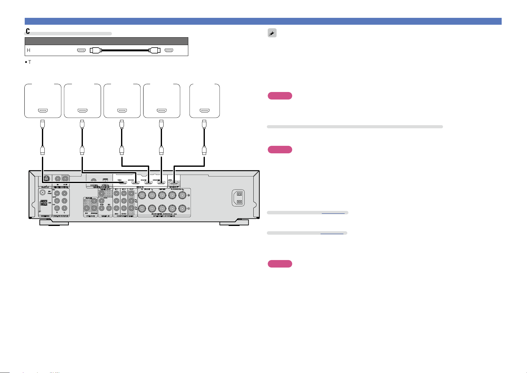
Cables used for connections
Audio and video cable (sold separately)
HDMI cable
•This interface allows transfer of digital video signals and digital audio signals over a single HDMI cable.
OUT
HDMI
OUT
HDMI
OUT
HDMI
OUT
HDMI
IN
HDMI
Blu-ray
Disc
player
DVD
player
TV
Set-top
box
Game
console
Basic version
Advanced version
Information
Basic version
7
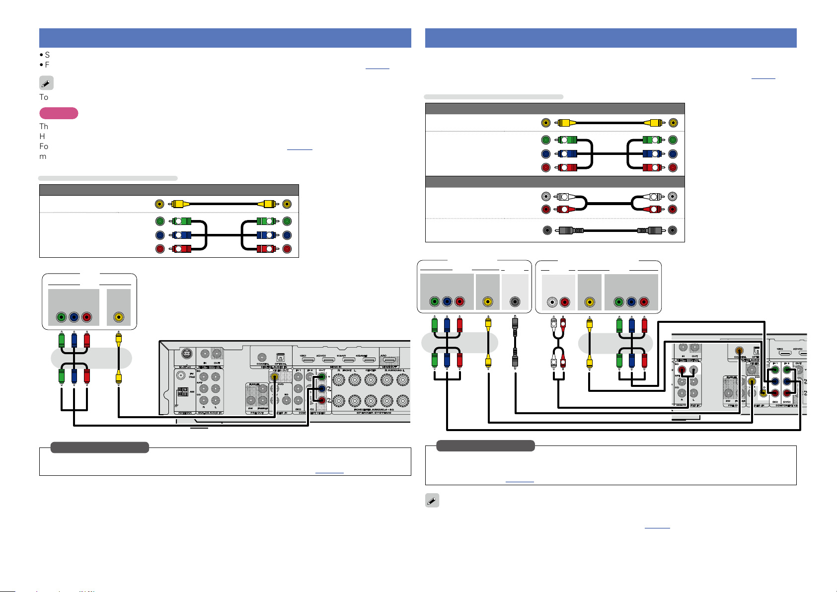
Connecting a Blu-ray Disc player/DVD player
•You can enjoy video and audio from a Blu-ray Disc or DVD.
•Select the connector to use and connect the device.
•For instructions on HDMI connections, see “Connecting an HDMI-compatible device” (vpage5).
Cables used for connections
Video cable (sold separately)
Video cable
Component video
cable
Y
PB
PR
Y
PB
PR
Audio cable (sold separately)
Audio cable
R
L
R
L
Coaxial digital cable
R
L
R
L
AUDIOAUDIO
AUDIO
RL
OUT
VIDEO
OUT
VIDEO
COMPONENT VIDEO
Y P
B PR
OUT
VIDEO
OUT
VIDEO
COMPONENT VIDEO
Y P
B PR
OUT
OUT
COAXIAL
DVD player
Blu-ray Disc player
Set this to change the digital input connector or component video input connector to which the input
source is assigned.
“Input Assign” (vpage64)
in Set as Necessary
When you want to play back HD Audio (Dolby TrueHD, DTS-HD, Dolby Digital Plus, DTS Express) and Multi-
channel PCM with this unit, use an HDMI connection (vpage 5 “Connecting an HDMI-compatible
device”).
Connecting a TV
•Select the connector to use and connect the device.
•For instructions on HDMI connections, see “Connecting an HDMI-compatible device” (vpage5).
To listen to TV audio through this device, use the optical digital connection.
NOTE
The optical connection is not required when a TV compatible with the ARC function (Audio Return Channel
HDMI 1.4a standard function) is connected to this unit via an HDMI connection.
For details, see “About ARC (Audio Return Channel) function” (vpage 5) or refer to the instruction
manual for your TV.
Cables used for connections
Video cable (sold separately)
Video cable
Component video
cable
Y
PB
PR
Y
PB
PR
IN
VIDEO
VIDEO
COMPONENT VIDEO
Y P
B PR
IN
TV
At the time of purchase, the OPTICAL input connector is assigned to “CD”. To use the OPTICAL input
connector for the TV audio input, change the settings of “Input Assign” (vpage64) in the menu.
in Set as Necessary
Basic version
Advanced version
Information
Basic version
8
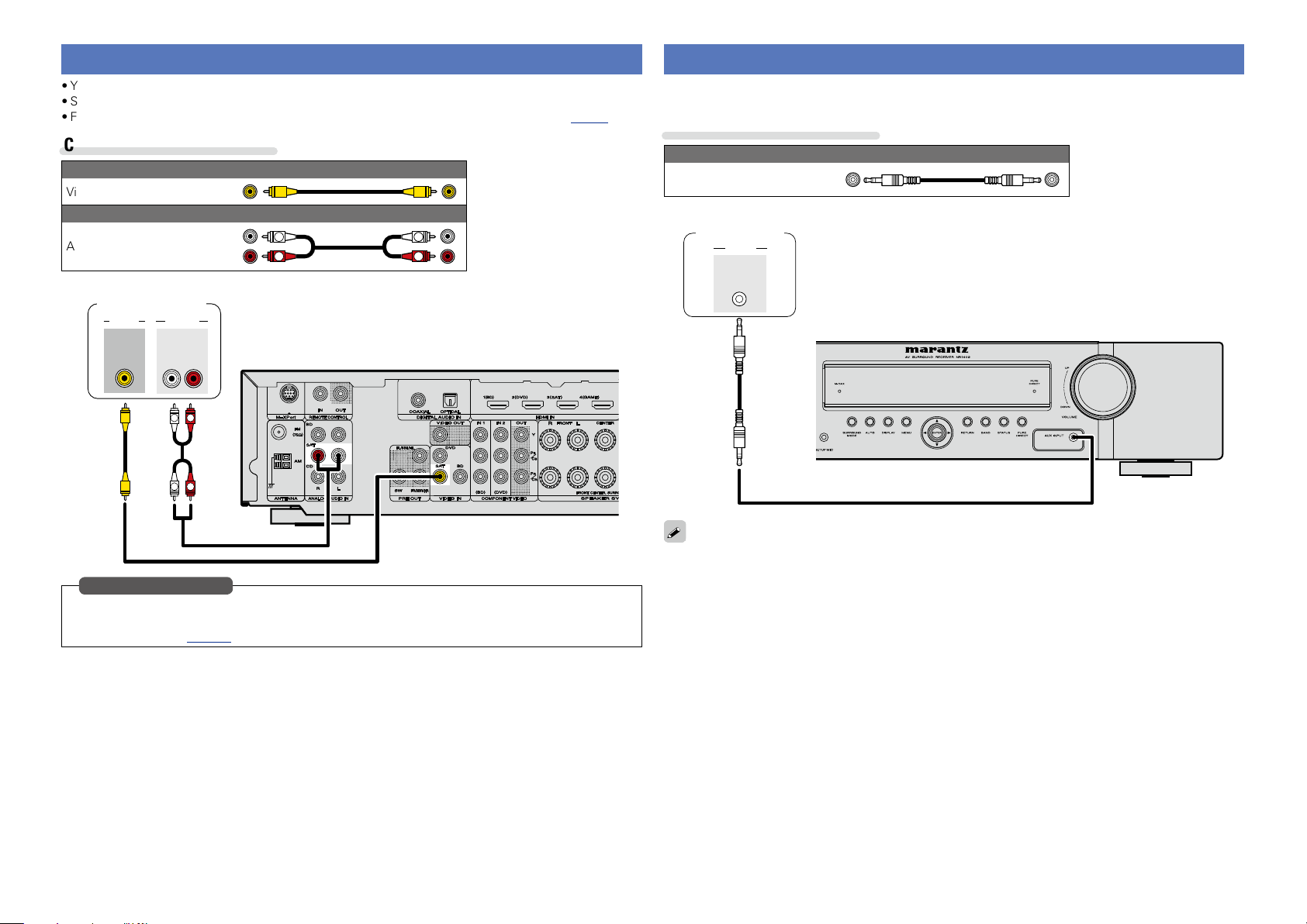
Connecting a portable audio player
If a portable player is connected via the AUX INPUT jack of the unit, music from the portable player can
be played.
Cables used for connections
Audio cable (sold separately)
Stereo mini
plug cable
AUDIO
AUDIO
OUT
Portable
audio player
You can enjoy listening to music by connecting a portable audio player via the AUX INPUT jack. In this case,
set the input source to “AUX”.
Connecting a set-top box (Satellite tuner/Cable TV)
•You can watch satellite or cable TV.
•Select the connector to use and connect the device.
•For instructions on HDMI connections, see “Connecting an HDMI-compatible device” (vpage5).
Cables used for connections
Video cable (sold separately)
Video cable
Audio cable (sold separately)
Audio cable
R
L
R
L
R
L
R
L
VIDEO
AUDIO
AUDIO
RL
OUT
OUT
VIDEO
Satellite tuner/
Cable TV
Set this to change the digital input connector or component video input connector to which the input
source is assigned.
“Input Assign” (vpage64)
in Set as Necessary
Basic version
Advanced version
Information
Basic version
9
Connecting a CD player
•You can enjoy CD sound.
•Select the connector to use and connect the device.
Cables used for connections
Audio cable (sold separately)
Audio cable
R
L
R
L
Optical cable
L
L
R
R
AUDIO
AUDIO
RL
OUT
OPTICAL
OUT
CD player
Set this to change the digital input connector to which the input
source is assigned.
“Input Assign” (vpage64)
in Set as Necessary
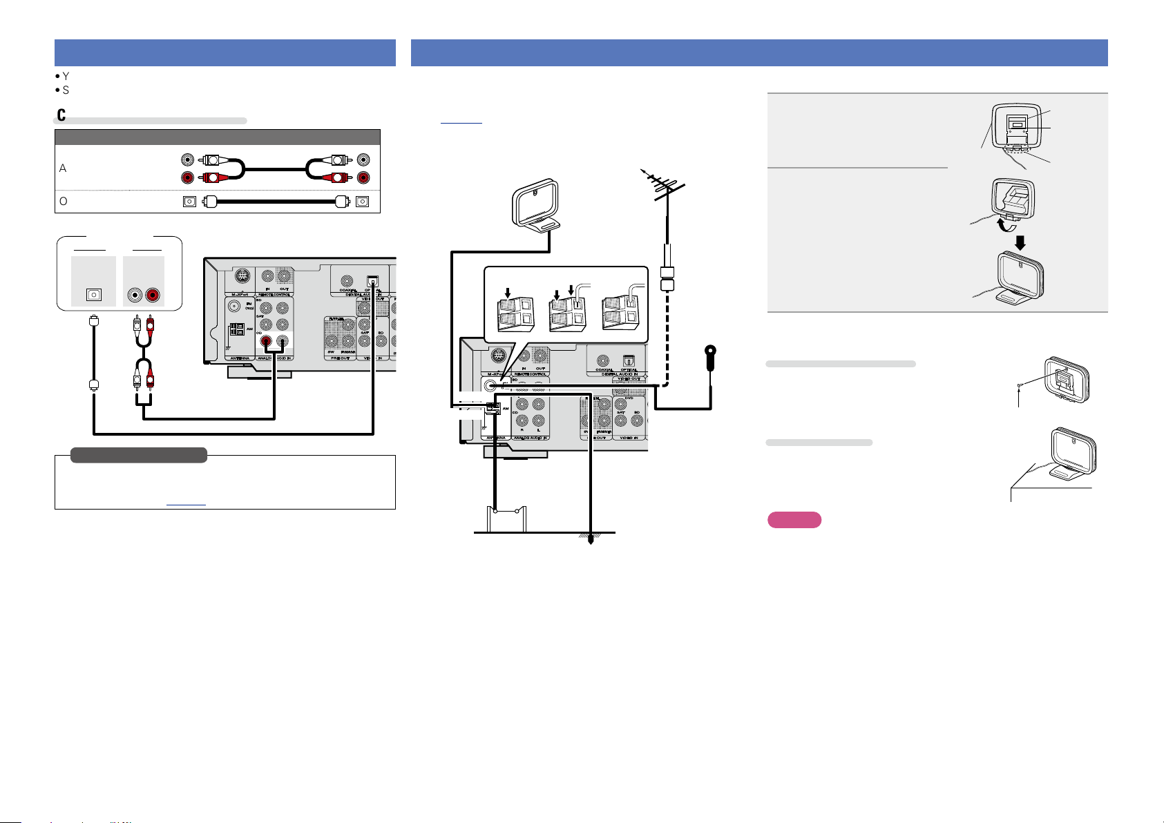
Connecting an antenna
•Connect the FM antenna or AM loop antenna supplied with the unit
to enjoy listening to radio broadcasts.
•After connecting the antenna and receiving a broadcast signal
(vpage 20 “Listening to FM/AM broadcasts”), fix the antenna
with tape in a position where the noise level becomes minimal.
w eq
FM outdoor
antenna
Direction of broadcasting station
75 Ω coaxial
cable
Ground
AM outdoor
antenna
AM loop antenna
(supplied)
Black
White
FM indoor
antenna
(supplied)
n AM loop antenna assembly
1
Put the stand section
through the bottom of the
loop antenna from the
rear and bend it forward.
Stand
Square
hole
Projecting
part
Loop
antenna
2
Insert the projecting part
into the square hole in
the stand.
n Using the AM loop antenna
Suspending on a wall
Suspend directly on a wall without assembling.
Nail, tack, etc.
Standing alone
Use the procedure shown above to assemble.
NOTE
•Do not connect two FM antennas simultaneously.
•Even if an external AM antenna is used, do not disconnect the AM
loop antenna.
•Make sure the AM loop antenna lead terminals do not touch metal
parts of the panel.
•If the signal has noise interference, connect the ground terminal
(GND) to reduce noise.
•If you are unable to receive a good broadcast signal, we recommend
installing an outdoor antenna. For details, inquire at the retail store
where you purchased the unit.
Basic version
Advanced version
Information
Basic version
10
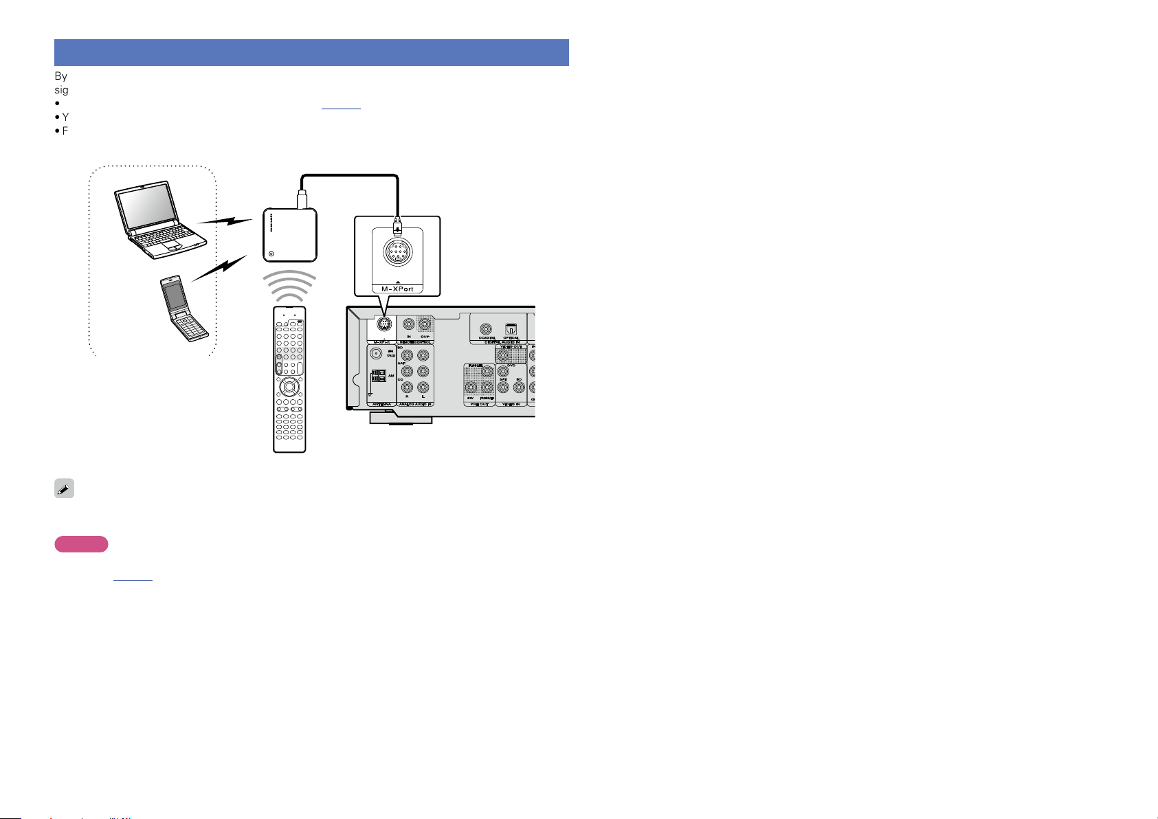
Connecting a wireless receiver (RX101)
By connecting a wireless receiver RX101 (sold separately) to this unit, you can receive and playback audio
signals from other devices using the Bluetooth Communication Function.
•Use a Bluetooth device that is A2DP compatible (vpage85 “A2DP”).
•You can also use wireless receiver RX101 as an external IR receiver.
•For instructions on the wireless receiver settings, refer to the RX101’s operating instructions.
Wireless receiver RX101
Bluetooth device
(A2DP Compatibility)
Remote control unit
You can enjoy listening to music by connecting a wireless receiver via the M-XPort input connector. In this
case, set the input source to “M-XPort”.
NOTE
To use wireless receiver RX101 as external IR receiver, set the remote sensor function of this unit to
disable (vpage67 “Remote control settings”).
Basic version
Advanced version
Information
Basic version
11
The acoustic characteristics of the connected speakers and
listening room are measured and the optimum settings are made
automatically. This is called “Audyssey
®
Auto Setup”.
To perform measurement, place the setup microphone in
multiple locations all around the listening area. For best results,
we recommend you measure in six positions, as shown in the
illustration (up to six positions).
•When performing Audyssey
®
Auto Setup, Audyssey MultEQ
®
/
Audyssey Dynamic EQ
®
/Audyssey Dynamic Volume
®
functions
become active (vpage50, 51).
•To set up the speakers manually, use “Speaker Setup”
(vpage55) on the menu.
NOTE
•Make the room as quiet as possible. Background noise can disrupt
the room measurements. Close windows, silence cell phones,
televisions, radios, air conditioners, fluorescent lights, home
appliances, light dimmers, or other devices as measurements may
be affected by these sounds.
•Cell phones should be placed away from all audio electronics during
the measurement process as Radio Frequency Interference (RFI)
may cause measurement disruptions (even if the cell phone is not
in use).
•Do not unplug the setup microphone from the main unit until
Audyssey
®
Auto Setup is completed.
•Do not stand between the speakers and setup microphone or allow
obstacles in the path while the measurements are being made. This
will cause inaccurate readings.
•Loud test sounds may be played during Audyssey
®
Auto setup. This
is part of normal operation. If there is background noise in room,
these test signals will increase in volume.
•Operating
VOLUME +, – during
the measurements will cancel the
measurements.
•Measurement cannot be performed when
headphones are connected.
Settings
Here, we explain “Audyssey
®
Auto Setup”, which allows you to
automatically make the optimal settings for your speakers.
Selecting a listening mode (Surround mode)
(vpage24)
Playback (Basic operation) (vpage18)
n Set up speakers (Audyssey
®
Auto Setup)
(vpage11)
Playback (Advanced operation) (vpage38)
Set up speakers (Audyssey
®
Auto Setup)
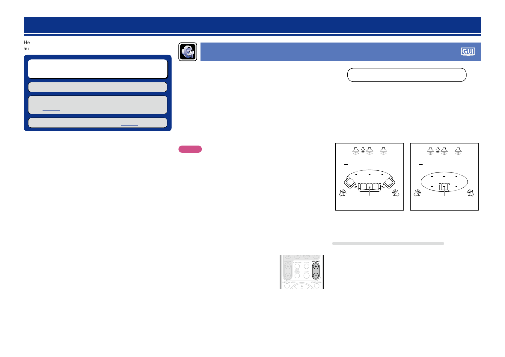
About setup microphone placement
•Measurements are performed by placing the setup microphone
successively at multiple positions throughout the entire listening
area, as shown in GExample qH. For best results, we recommend
you measure in six positions, as shown in the illustration (up to six
positions).
•Even if the listening environment is small as shown in GExample wH,
measuring at multiple points throughout the listening environment
results in more effective correction.
FL SW C FR
SRSL
*
M
FL SW C FR
SRSL
*
M
(
: Measuring positions)
GExample qH GExample wH
(
: Measuring positions)
FL Front speaker (L) SW Subwoofer
FR Front speaker (R) SL Surround speaker (L)
C Center speaker SR Surround speaker (R)
About the main listening position (*M)
The main listening position is the position where listeners would
normally sit or where one would normally sit alone within the listening
environment. Before starting Audyssey
®
Auto Setup, place the setup
microphone in the main listening position. Audyssey MultEQ
®
uses
the measurements from this position to calculate speaker distance,
level, polarity, and the optimum crossover value for the subwoofer.
Basic version
Advanced version
Information
Basic version
vSee overleaf
12
2
Set up the subwoofer
If using a subwoofer capable of the following
adjustments, set up the subwoofer as shown below.
n When using a subwoofer with a direct mode
Set the direct mode to “On” and disable the volume adjustment
and crossover frequency setting.
n When using a subwoofer without a direct mode
Make the following settings:
•Volume : “12 o’clock position”
•Crossover frequency : “Maximum/Highest Frequency”
•Low pass filter : “Off”
•Standby mode : “Off”
1
Set up the microphone
Mount the setup microphone on a tripod or stand
and place it in the main listening position.
When placing the setup microphone, adjust the height of the
sound receptor to the level of the listener’s ear.
Sound receptor
Setup
microphone
If you do not have a tripod or stand, set up the microphone on, for
example, a seat without a back.
NOTE
•Do not hold the setup microphone in your hand during
measurements.
•Avoid placing the setup microphone close to a seat back or wall as
sound reflections may give inaccurate results.
Set up speakers (Audyssey
®
Auto Setup)
3
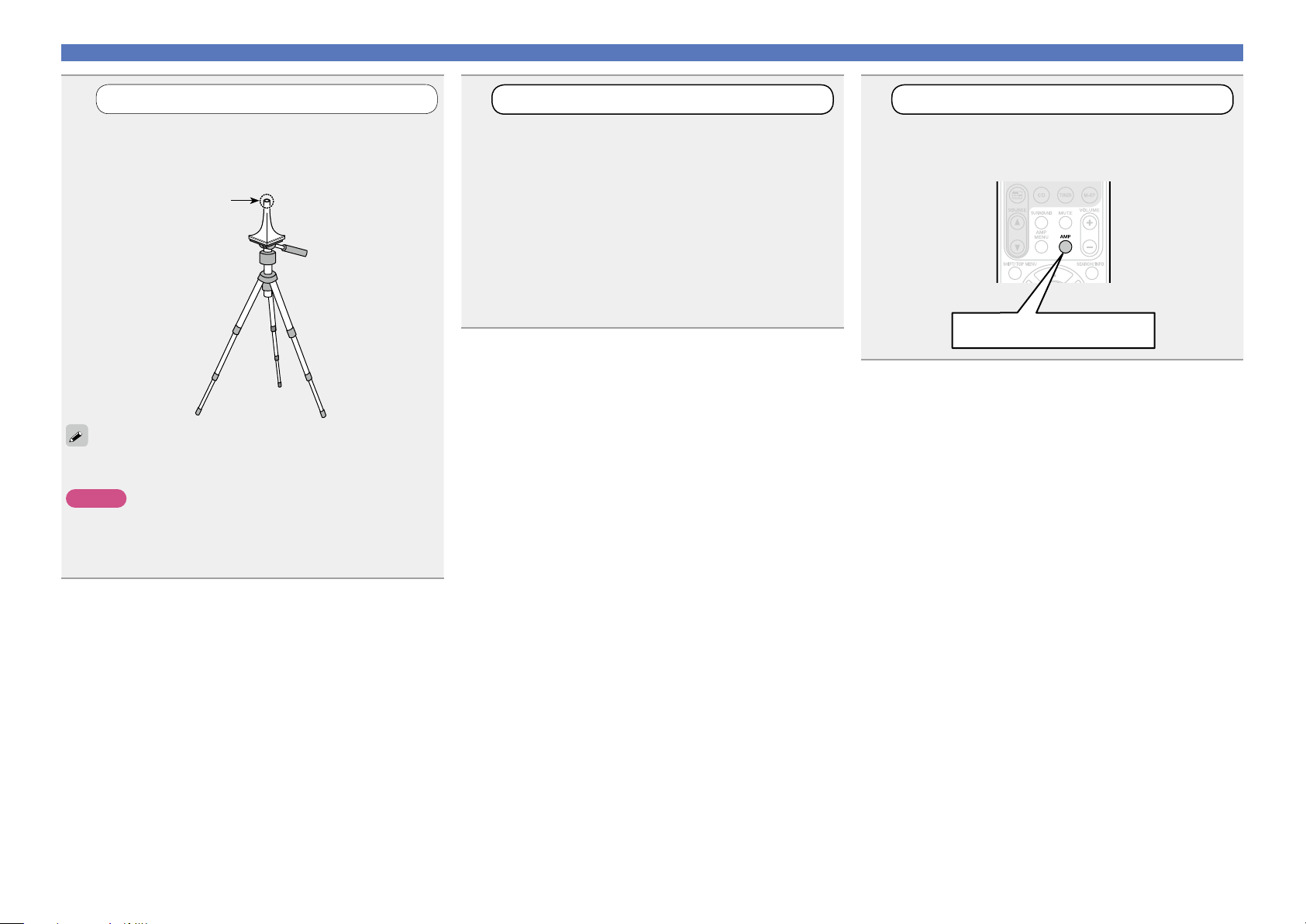
Set up the remote control unit
n Set up the operation mode
Press AMP to set the remote control unit to AMP-
operation mode.
Press AMP
Basic version
Advanced version
Information
Basic version
vSee overleaf
13
STEP 1
Preparation
STEP 2
Detect & Measure (Main)
Set up speakers (Audyssey
®
Auto Setup)
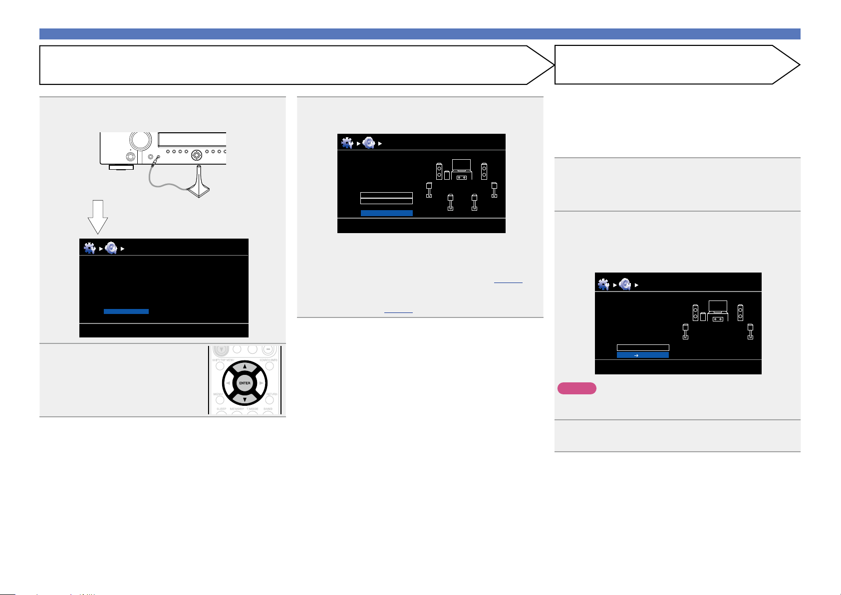
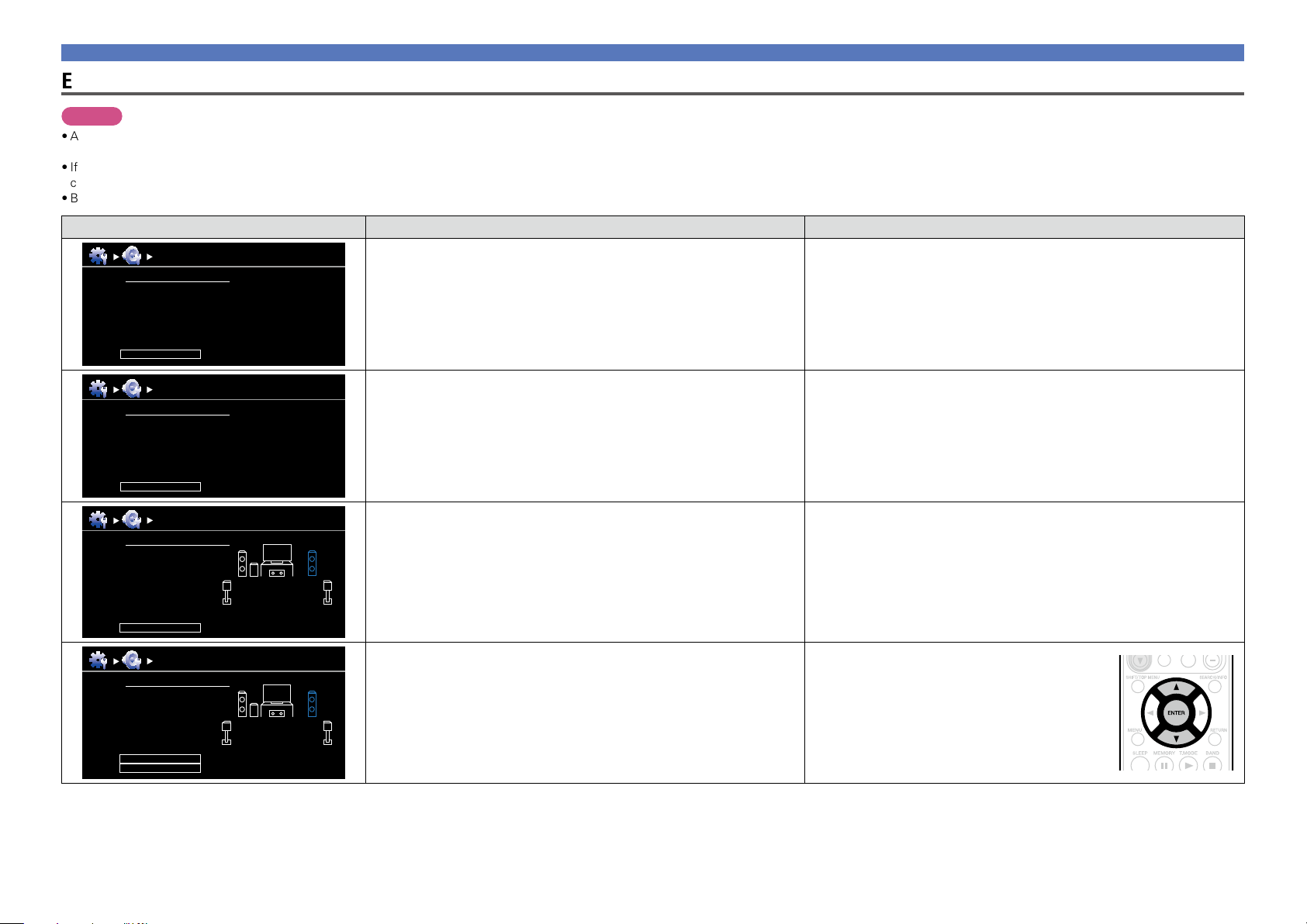
4
Connect the setup microphone to the SETUP MIC
jack of this unit.
MultEQ
Preparation
Connect the speakers and place them according
to the recommendations in the manual.
Next
Audyssey Auto Setup
[RETURN][ENTER] Enter Cancel
When the setup microphone is
connected, the following screen is
displayed.
5
Select “Next” and then press
ENTER.
•In STEP 2, you will perform measurements at the main listening
position.
•This step automatically checks the speaker configuration and speaker
size, and calculates the channel level, distance, and crossover
frequency.
It also corrects distortion in the listening area.
7
Select “Measure” and then press ENTER.
When measuring begins, a test tone is output from each
speaker.
•Measurement requires several minutes.
8
The detected speakers are displayed.
•The illustration below shows an example of when the front
speakers, center speaker, subwoofer, and surround speakers have
been detected.
Detect Check
Front
Center
Subwoofer
Surround
S.Back
Retry
Next Measure
Yes
Yes
Yes
Yes
No
Audyssey Auto Setup MultEQ
[RETURN][ENTER] Enter Cancel
NOTE
If a connected speaker is not displayed, the speaker may not be
connected correctly. Check the speaker connection.
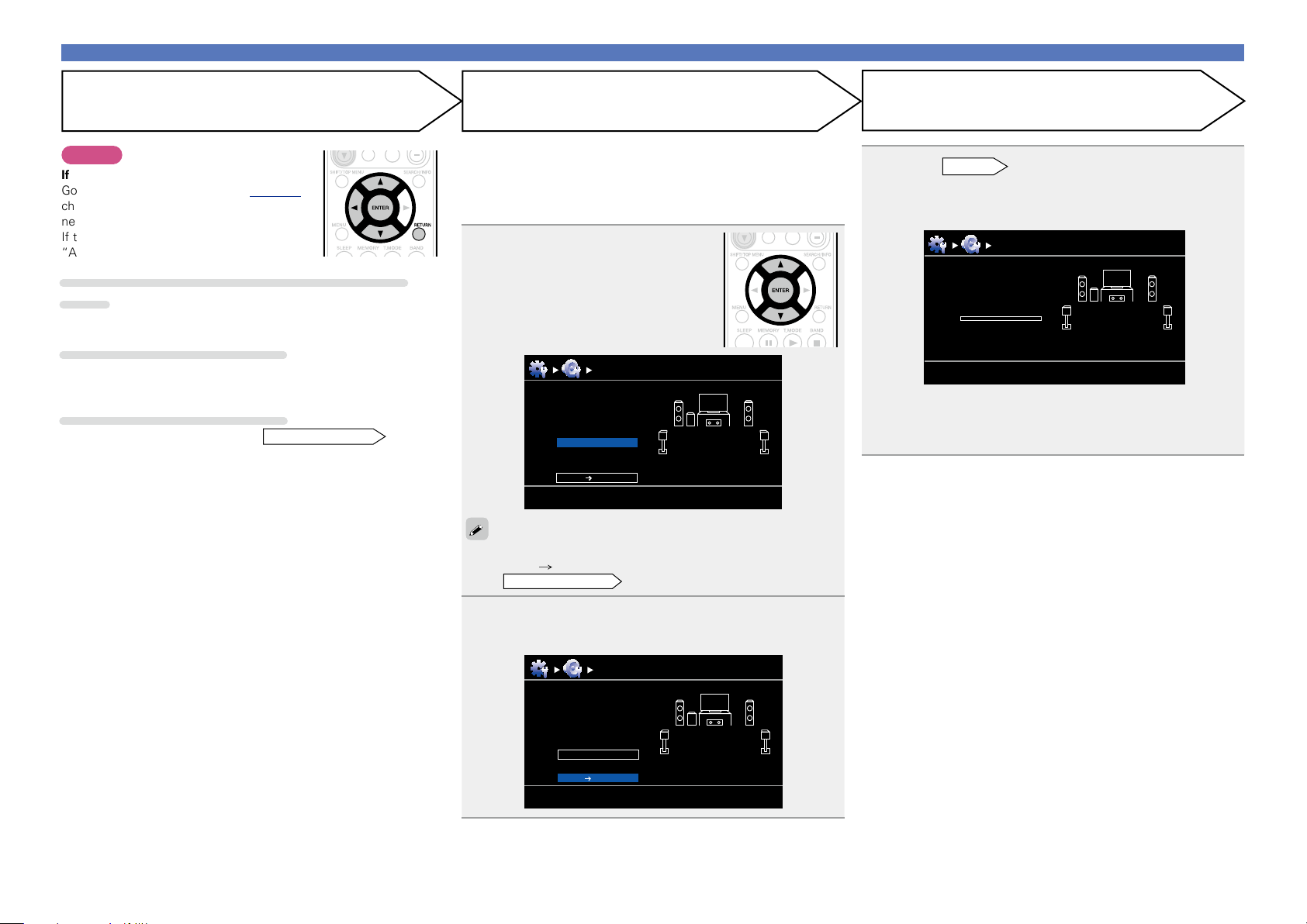
9
Use ui to select “Next → Measure” and then press
ENTER.
6
Use ui to select “Auto Setup Start” and then press
ENTER.
Preparation
Set the following items
if necessary.
Pre Assign
Channel Select
Auto Setup Start
Audyssey Auto Setup MultEQ
[RETURN][ENTER] Enter Cancel
Here, we explain setup using the example of 5.1-channel speaker
playback.
For settings other than 5.1-channel surround, select “Pre Assign”
and perform step 4 to 5 of “Set up “Pre Assign”” (vpage35).
If unused channels are set with “Channel Select”, measuring time
can be shortened. For setting, perform steps 7 to 11 of “Set up
“Channel Select”” (vpage36).
Basic version
Advanced version
Information
Basic version
vSee overleaf
14
STEP 4
Calculate
Set up speakers (Audyssey
®
Auto Setup)
•In STEP 3, you will perform measurements at multiple positions (two
to six positions) other than the main listening position.
•Just one position can be measured but measuring multiple positions
increases the accuracy of the correction of acoustic distortion within
the listening area.
10
Move the setup microphone to
position 2, use ui to select
“Measure”, and then press
ENTER.
The measurement of the second
position starts. Measurements can be
made in up to six positions.
Audyssey Auto Setup MultEQ
Measure (2nd)
Please place the
microphone at ear
height at 2nd
listening position.
Measure
Next Calculate
[RETURN][ENTER] Enter Cancel
If you want to omit measurements from the next position onward,
select “Next Calculate”.
(Go to
STEP4 Calculate
)
11
Repeat step 10, measuring positions 3 to 6.
When measurement of position 6 is completed, a
“Measurements finished.” message is displayed.
Audyssey Auto Setup MultEQ
Measure (Finish)
Measurements finished.
Next Calculate
Retry
[RETURN][ENTER] Enter Cancel
12
On the
STEP 3
screen, use ui to select “Next →
Calculate”, and then press ENTER.
Measuring results are analyzed, and the frequency response of
each speaker in the listening room is determined.
Audyssey Auto Setup MultEQ
Calculate
Now calculating
Please wait
0%
•Analysis takes several minutes to complete. The time required for
this analysis depends on the number of speakers connected.
The more connected speakers there are, the longer it takes to
perform analysis.
STEP 3
Measure (2nd – 6th)
STEP 2 (Continued)
Detect & Measure (Main)
NOTE
If “Caution!” is displayed:
Go to “Error messages” (vpage 16),
check any related items, and perform the
necessary procedures.
If the problem is resolved, return and restart
“Audyssey
®
Auto Setup”.
When performing Audyssey
®
Auto Setup over
again
Press ui to select “Retry”, and then press ENTER.
When measuring has stopped
q Press RETURN, to the “Cancel Auto Setup?” prompt is displayed.
w Press o to select “Yes”, then press ENTER.
Setting up the speakers again
Repeat the operation from step 4 of
STEP 1 Preparation
.
Basic version
Advanced version
Information
Basic version
vSee overleaf
15
Set up speakers (Audyssey
®
Auto Setup)
15
Select “Store” and then press ENTER.
Save the measurement results.
Audyssey Auto Setup MultEQ
Store
Now storing
Please wait
0%
Audyssey Auto Setup MultEQ
Store
Press “Store” to
store calculation
result.
Store
[RETURN][ENTER] Enter Cancel
•Saving the results requires about 10 seconds.
•If the measuring results are not to be saved, press RETURN. A
message “Cancel Auto Setup?” will be displayed. Press o then
select “Yes”. All the measured Audyssey
®
Auto Setup data will
be erased.
•During saving of measurements results, “Now storing Please
wait” is displayed. When saving is completed, “Storing complete.
Auto Setup is now finished.” is displayed.
NOTE
During saving of measurement results, be sure not to turn off the
power.
16
Unplug the setup microphone from the unit’s SETUP
MIC jack.
17
Set Audyssey Dynamic Volume
®
.
Finish
Storing complete.
Auto Setup is now finished.
Please unplug microphone.
Turn on Dynamic Volume?
Yes
No
[ENTER] Exit
Audyssey Auto Setup MultEQ
•This feature adjusts the output volume to the optimal level while
constantly monitoring the level of the audio input to the unit.
Optimal volume control is performed automatically without any
loss in the dynamism and clarity of the sound when, for example,
the volume suddenly increases for commercials shown during
television programs.
n When turning Dynamic Volume
®
on
•Use u to select “Yes”, and then press ENTER.
The unit automatically enters “Medium” mode.
n When turning Dynamic Volume
®
off
•Use i to select “No”, and then press ENTER.
NOTE
After performing Audyssey
®
Auto Setup, do not change the speaker
connections or subwoofer volume. In event of a change, perform
Audyssey
®
Auto Setup again.
STEP 6
Store
Finish
STEP 5
Check
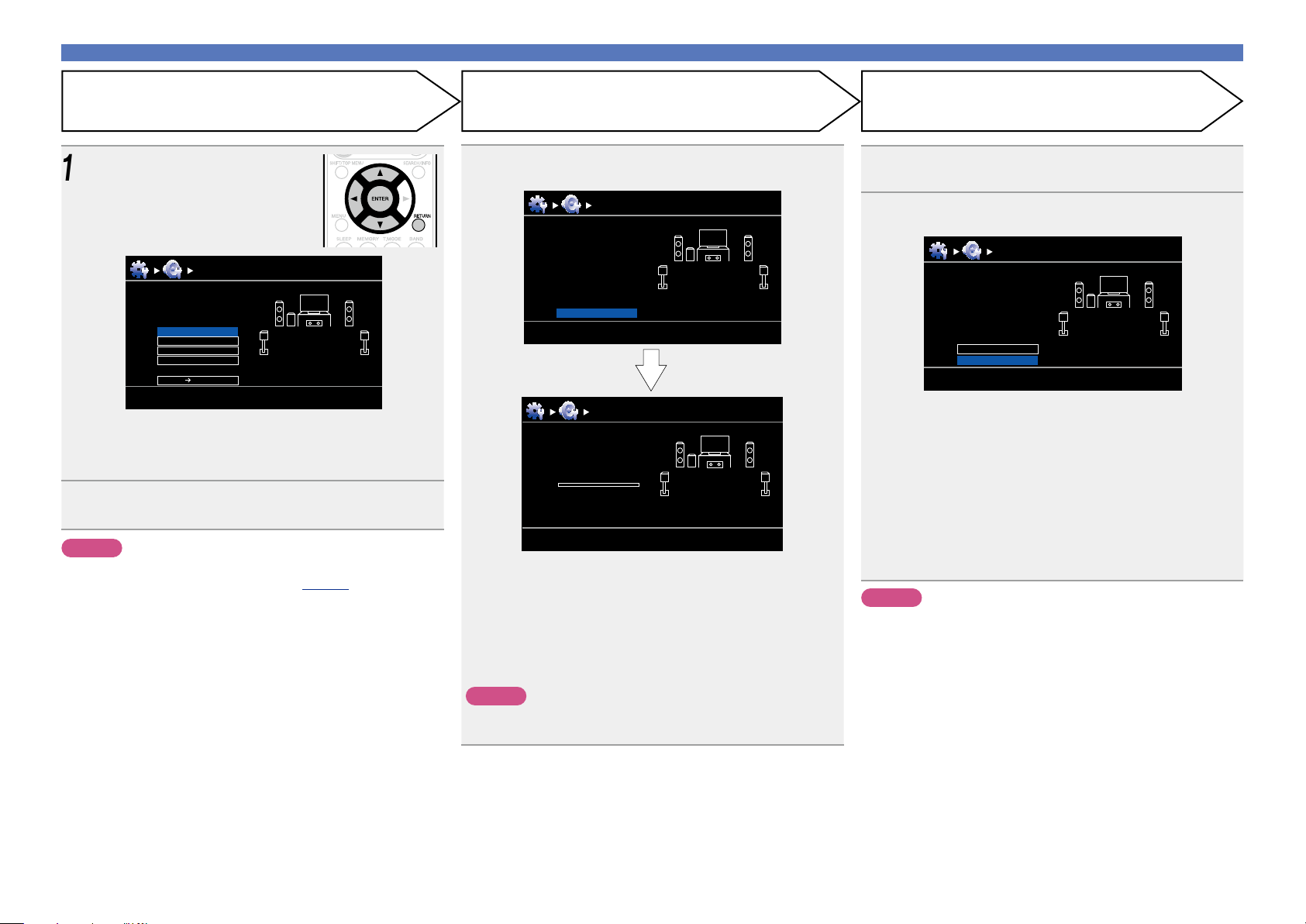
13
Use ui to select the item you
want to check, and then press
ENTER.
MultEQ
Check
Check processing resuit.
To proceed, press
“Next”.
Next Store
Sp.Config. Check
Distance Check
Ch.Level Check
Crossover Check
Audyssey Auto Setup
[RETURN][ENTER] Enter Cancel
•Subwoofers may measure a greater reported distance than
the actual distance due to added electrical delay common in
subwoofers.
•If you want to check another item, press RETURN.
14
Use ui to select “Next → Store” and then press
ENTER.
NOTE
•If the result differs from the actual connection status, or if “Caution!”
is displayed, see “Error messages” (vpage 16). Then carry out
Audyssey
®
Auto Setup again.
• If you change speaker positions or orientation, perform Audyssey
®
Auto Setup again to find the optimal equalizer settings.
Basic version
Advanced version
Information
Basic version
16
Error messages
NOTE
•An error message is displayed if Audyssey
®
Auto Setup could not be completed due to speaker placement, the measurement environment, etc. If this happens, check the relevant items, be sure to take the necessary
measures, then perform Audyssey
®
Auto Setup over again.
•If the result still differs from the actual connection status after remeasurement or the error message still appears, it is possible that the speakers are not connected properly. Turn this unit off, check the speaker
connections and repeat the measurement process from the beginning.
•Be sure to turn off the power before checking speaker connections.
Examples Error details Measures
MultEQ
Caution!
Microphone or Speaker is none
Retry
Audyssey Auto Setup
•The connected setup microphone is broken, or a device other than the
supplied setup microphone is connected.
•Not all speakers could be detected.
•The front L speaker was not properly detected.
•Connect the included setup microphone to the SETUP MIC jack of this unit.
•Check the speaker connections.
MultEQ
Caution!
Ambient noise is too high or level is too low
Retry
Audyssey Auto Setup
•There is too much noise in the room for accurate measurements to be
made.
•Speaker or subwoofer sound is too low for accurate measurements to be
made.
•Either turn off any device generating noise or move it away.
•Perform again when the surroundings are quieter.
•Check the speaker installation and the direction in which the speakers are
facing.
•Adjust the subwoofer’s volume.
MultEQ
Audyssey Auto Setup
Caution! Speaker:None
Front R
Retry
•The displayed speaker could not be detected.
(The screen on the left indicates that the front right speaker cannot be
detected.)
•Check the connections of the displayed speaker.
MultEQ
Audyssey Auto Setup
Caution! Speaker:Phase
Front R
Skip
Retry
•The displayed speaker is connected with the polarity reversed.
(The screen on the left indicates that the polarity phases of the front right
speakers are reversed.)
•Check the polarity of the displayed speaker.
•For some speakers, this error message may be
displayed even if the speaker is properly connected.
If you are sure the connection is correct, press ui
to select “Skip”, then press ENTER.
Set up speakers (Audyssey
®
Auto Setup)
Basic version
Advanced version
Information
Basic version
17
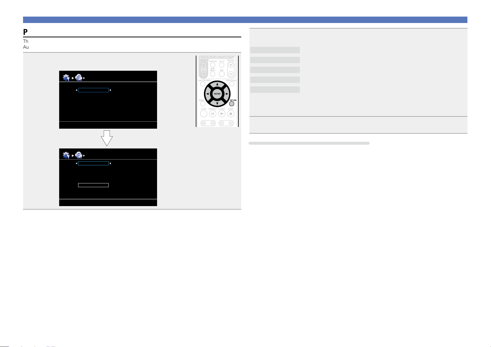
Parameter Check
This function enables you to check the measurement results and equalizer characteristics after Audyssey
®
Auto Setup.
1
Use ui to select “Parameter Check” and then press ENTER.
Sp. Config. Check
Distance Check
Ch. Level Check
Crossover Check
EQ Check
Restore
Parameter Check
Auto Setup
Parameter Check
Auto Setup
Sp. Config. Check
Distance Check
Ch. Level Check
Crossover Check
EQ Check
Set up speakers (Audyssey
®
Auto Setup)
2
Use ui to select the item you want to check, then press ENTER or p.
Measurement results for each speaker are displayed.
Sp. Config. Check
Check the speaker configuration.
Distance Check
Check the distance.
Ch. Level Check
Check the channel level.
Crossover Check
Check the crossover frequency.
EQ Check
Check the equalizer.
•If “EQ Check” is selected, press ui to select equalizing curve (“Audyssey” or “Audyssey Flat”) to
be checked.
Use
o p to switch the display between the different speakers.
3
Press RETURN.
The confirmation screen reappears. Repeat step 2.
Retrieving Audyssey
®
Auto Setup settings
If you set “Restore” to “Yes”, you can return to Audyssey
®
Auto Setup measurement result (value
calculated at the start by MultEQ
®
) even when you have changed each setting manually.
Basic version
Advanced version
Information
Basic version
18
Playback (Basic operation)
n Playing a Blu-ray Disc player/DVD player
(vpage19)
n Playing a CD player (vpage19)
n Tuning in radio stations (vpage20)
Selecting a listening mode (Surround mode)
(vpage24)
n Selecting the input source (vpage18)
n Adjusting the master volume (vpage19)
n Turning off the sound temporarily (vpage19)
Playback (Advanced operation) (vpage38)
Settings (vpage11)
Important information
Before starting playback, make the connections between the different
devices and the settings on the unit.
NOTE
Also refer to the operating instructions of the connected devices
when playing them.
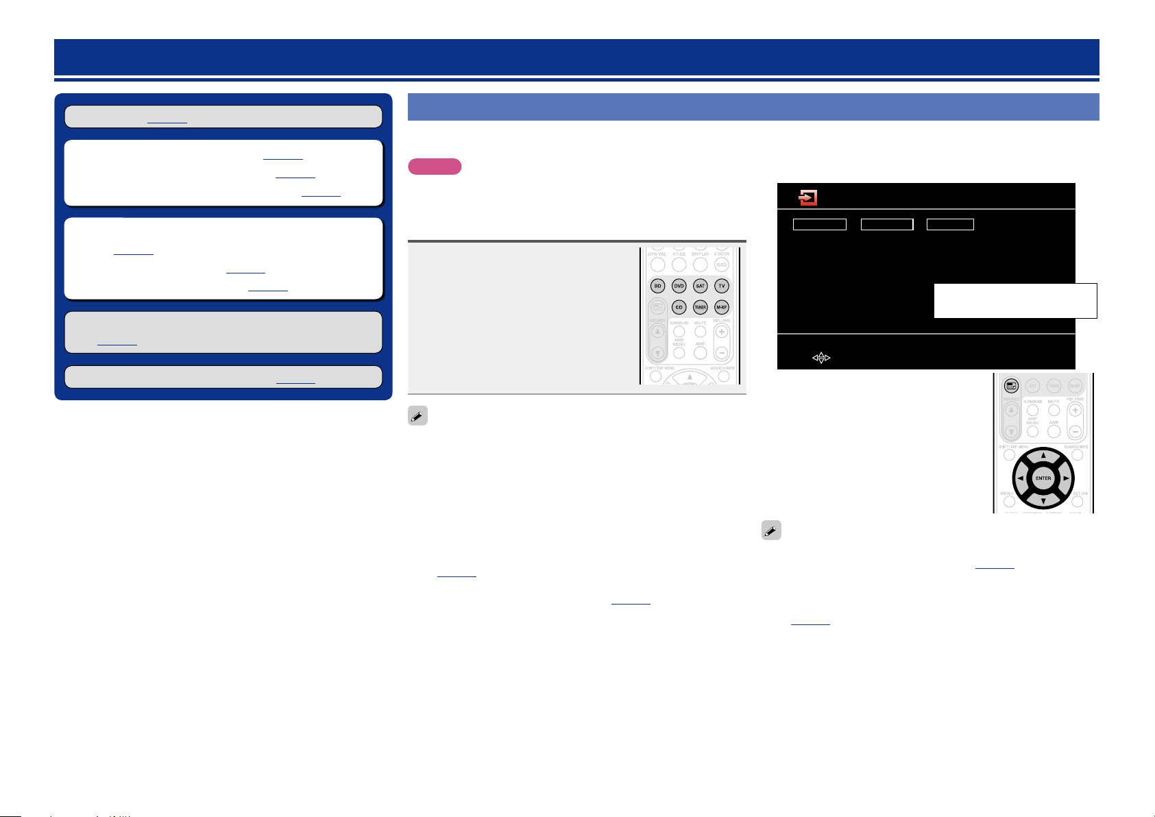
Selecting the input source
Press the input source select button
(BD, DVD, SAT, TV, CD, TUNER or
M-XP) twice to be played back.
When an input source select button (BD, DVD,
SAT, TV, CD, TUNER or M-XP) is pressed
once, the unit switches to device selected
by the operating mode of the remote control.
If the input source select button is then
pressed again twice, the input source for the
unit is switched.
Select input source “AUX” to play back music from an audio system
connected to the AUX INPUT jack.
The input source “GAME” is selected to playback from a game device
connected to GAME connector of HDMI IN.
Select the input source “AUX” or “GAME” using one of the following
methods.
•“Source Select” menu
(“Using the “Source Select” menu” provided on the right)
•SOURCE d f button on the remote control unit
(“Using the SOURCE d f button on the remote control unit”
(vpage19))
•INPUT SELECTOR knob on the main unit
(“Using the knob on the main unit” (vpage19))
You can also use the following operation to select an input
source.
n Using the “Source Select” menu
Player
BD
DVD
CD
M-XPort
Video
SAT
TV
GAME
AUX
Tuner
TUNER
[ENTER] Enter[ ] Move
Source Select
The currently selected input
source is highlighted.
q Press 3.
Display the “Source Select” menu.
w Use uio p to select the input source,
then press ENTER.
The input source is set and the source
selection menu is turned off.
•Input sources that are not going to be used can be set ahead of time.
Make this setting at “Source Delete” (vpage59).
•To turn off the source selection menu without selecting an input
source, press 3 again.
•When 3 is pressed, the AMP-operation mode starts automatically
(vpage68).
Basic version
Advanced version
Information
Basic version
BD
vSee overleaf
19
n Using the SOURCE d
f button on the remote
control unit
Press SOURCE d or SOURCE f.
•Every time you press SOURCE d or
SOURCE f, the input source switches in
the following order.
DVD SATBD
TUNERM-XPort
GAME
CD
AUX
TV
n Using the knob on the main unit
Turn INPUT SELECTOR.
•Every time you turn
INPUT SELECTOR, the input source switches
in the following order.
DVD SATBD
TUNERM-XPort
GAME
CD
AUX
TV
Adjusting the master volume
Use VOLUME +, – to adjust the
volume.
n When the “Volume Display” setting
(vpage59) is “Relative”
GAdjustable rangeH
– – –
–80.5dB – 18.0dB
n When the “Volume Display” setting (vpage59) is
“Absolute”
GAdjustable rangeH
0.0 – 99.0
•The variable range differs according to the input signal and channel
level setting.
You can also operate via the main unit. In this case, perform the
following operations.
Turn VOLUME to adjust the volume.
Turning off the sound temporarily
Press MUTE.
•“MUTE” indicator on the display lights.
•
appears on a TV screen.
•The sound is reduced to the level set at “Mute Level” (vpage59).
•To cancel, press MUTE again. Muting can also be canceled by
adjusting the master volume.
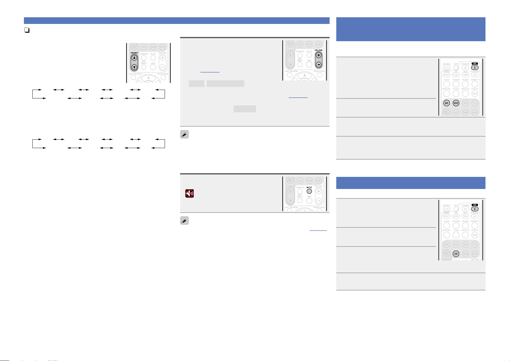
Playing a Blu-ray Disc player/DVD
player
The following describes the procedure for playing Blu-ray Disc player/
DVD player.
1
Prepare for playback.
q Turn on the power of the TV,
subwoofer and player.
w Change the TV input to the input of
this unit.
e Load the disc in the player.
2
Press ON to turn on power to the
unit.
3
Press BD or DVD twice to switch an input source for
a player used for playback.
4
Play the device connected to this unit.
Make the necessary settings on the player (language setting,
subtitles setting, etc.) beforehand.
Playing a CD player
The following describes the procedure for playing CD player.
1
Prepare for playback.
q Turn on the power of the subwoofer
and player.
w Load the disc in the player.
2
Press ON to turn on power to the
unit.
3
Press CD twice to switch an input
source for a player used for
playback.
4
Play the device connected to this unit.
Important information
Basic version
Advanced version
Information
Basic version
BD
20
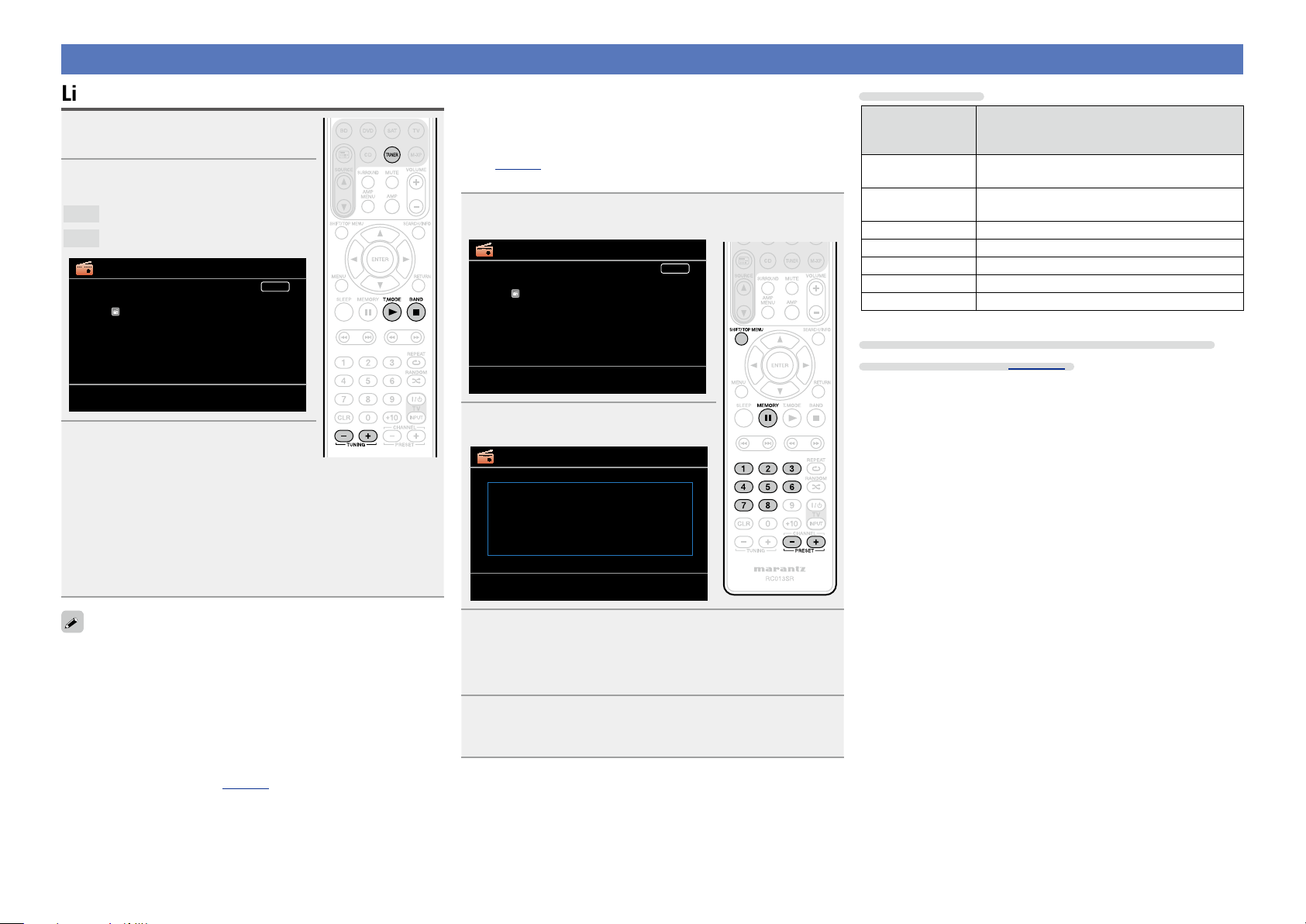
Tuning in radio stations
Listening to FM/AM broadcasts
1
Press TUNER twice to switch the
input source to “TUNER”.
2
Press BAND to select “FM” or
“AM”.
FM
When listening to an FM broadcast.
AM
When listening to an AM broadcast.
TUNER
A1
FM 87.50MHz
Now Playing
AUTO
[
MEMORY
]
Band
Memory
[
T.MODE
] Mode[BAND]
[
PRESET+/-
] Preset
Tuning[
TUNING+/-
]
[
SEARCH
] Search
3
Tune in the desired broadcast
station.
q To tune in automatically (Auto tuning)
Press T.MODE to light the “AUTO” indicator on the display, then
use TUNING + or TUNING – to select the station you want to
hear.
w To tune in manually (Manual tuning)
Press T.MODE to turn off the display’s “AUTO” indicator, then
use TUNING + or TUNING – to select the station you want to
hear.
•You can also operate via the main unit.
In this case, perform the following operations.
Press BAND to select “FM” or “AM”.
Press ui to select the station you want to hear.
•If the desired station cannot be tuned in with auto tuning, tune it in
manually.
•When tuning in stations manually, press and hold TUNING + or
TUNING – to change frequencies continuously.
•The time (default : 30 sec) for which the menu are displayed can be
set at menu “Tuner” (vpage 60). Press uio p to return to
the original screen.
n Presetting radio stations (Manual preset)
Your favorite broadcast stations can be preset so that you can tune
them in easily. Up to 56 stations can be preset.
•Stations can be preset automatically at “Auto Preset”
(vpage63). If “Auto Preset” is performed after performing
“Manual preset”, the “Manual preset” settings will be overwritten.
1
Tune in the broadcast station you want to preset.
TUNER
A1
FM 87.50MHz
Now Playing
AUTO
[
MEMORY
]
Band
Memory
[
T.MODE
] Mode[BAND]
[
PRESET+/-
] Preset
Tuning[
TUNING+/-
]
[
SEARCH
] Search
2
Press MEMORY.
TUNER
A1
To store preset:
Select
A1-G8
[
MEMORY
][
1-8
][
SHIFT
]
[
MEMORY
]
Band
Memory
[
T.MODE
] Mode[BAND]
[
PRESET+/-
] Preset
Tuning[
TUNING+/-
]
[
SEARCH
] Search
3
Press SHIFT/TOP MENU to select the block (A to G) in
which the channel (1 to 8 per a block) is to be preset,
then press PRESET +, PRESET – or 1 – 8 to select the
preset number.
4
Press MEMORY again to complete the setting.
•To preset other stations, repeat steps 1 to 4.
Default settings
Block (A – G)
and
Channel (1 – 8)
Default Settings
A1 – A8
87.50 / 89.10 / 98.10 / 108.00 / 90.10 / 90.10 /
90.10 / 90.10 MHz
B1 – B8
522 / 603 / 999 / 1404 / 1611 kHz,
90.10 / 90.10 / 90.10 MHz
C1 – C8 90.10 MHz
D1 – D8 90.10 MHz
E1 – E8 90.10 MHz
F1 – F8 90.10 MHz
G1 – G8 90.10 MHz
Specify a name for the preset broadcast station
(Preset Name) (vpage63)
Basic version
Advanced version
Information
Basic version
vSee overleaf
BD
21
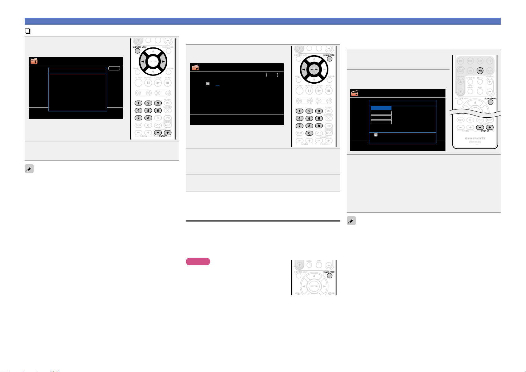
Tuning in radio stations
n Listening to preset stations
1
Press SHIFT/TOP MENU to select
the memory block (A to G).
TUNER
AUTO
[
MEMORY
]
Band
Memory
[
T.MODE
] Mode[BAND]
[
PRESET+/-
] Preset
Tuning[
TUNING+/-
]
Preset Channel
A8 FM 90.10MHz
A7 FM 90.10MHz
A6 FM 90.10MHz
A5 FM 90.10MHz
A4 FM 108.00MHz
A3 FM 98.10MHz
A2 FM 89.10MHz
A1 FM 87.50MHz
2
Press PRESET +, PRESET – or 1 – 8 to select the
desired preset channel.
You can also operate via the main unit. In this case, perform the
following operations.
Press o p to select a preset radio station.
n Direct frequency tuning
You can enter the receiving frequency directly to tune in.
1
Press SEARCH/INFO.
TUNER
FM ---.-- MHz
DIRECT TUNE
B6
Now Playing
AUTO
[
MEMORY
]
Band
Memory
[
T.MODE
] Mode[BAND]
[
PRESET+/-
] Preset
Tuning[
TUNING+/-
]
[
SEARCH
] Search
2
Input frequencies using the 0 – 9.
•If o is pressed, the immediately preceding input is cancelled.
3
When setting is completed, press ENTER.
The preset frequency is tuned in.
RDS (Radio Data System)
Note that the RDS function only works when receiving RDS compatible
stations.
RDS (works only on the FM band) is a broadcasting service which
allows a station to send additional information along with the regular
radio program signal.
NOTE
The operations described as follows using
SEARCH/INFO will not function in areas in
which there are no RDS broadcasts.
n RDS search
Use this function to automatically tune to FM stations that provide
the RDS service.
1
Press TUNER twice to switch the
input source to “TUNER”.
2
Press SEARCH/INFO to select
“RDS”.
TUNER
[
MEMORY
]
Band
Memory
[
T.MODE
] Mode[BAND]
[
PRESET+/-
] Preset
Tuning[
TUNING+/-
]
[
SEARCH
] Search
RDS
RDS station
Program category
Traffic info
Radio text
RDS
PTY
TP
RT
[
PRESET+/-
] Tuning
[
SEARCH
]SearchMode
FM 90.10MHz
3
Press PRESET + or PRESET –.
The search for RDS stations begins automatically.
•If no RDS stations are found with the above operation, all the
reception bands are searched.
•When a broadcast station is found, that station’s name appears on
the display.
•If no RDS station is found when all the frequencies have been
searched, “NO RDS” is displayed.
If you press PRESET + or PRESET – within 5 seconds after the
broadcast station name is shown on the display, you can search for a
different station.
Basic version
Advanced version
Information
Basic version
BD
22
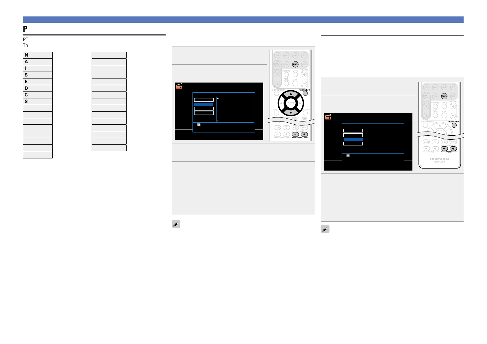
PTY (Program Type)
PTY identifies the type of RDS program.
The program types and their displays are as follows:
NEWS News WEATHER Weather
AFFAIRS Current Affairs FINANCE Finance
INFO Information
CHILDREN
Children’s
program
SPORT Sports
EDUCATE Education SOCIAL Social Affairs
DRAMA Drama RELIGION Religion
CULTURE Culture PHONE IN Phone In
SCIENCE Science TRAVEL Travel
VARIED Varied LEISURE Leisure
POP M Pop Music JAZZ Jazz Music
ROCK M Rock Music COUNTRY Country Music
EASY M
Easy Listening
Music
NATION M National Music
OLDIES Oldies Music
LIGHT M Light Classical FOLK M Folk Music
CLASSICS Serious Classical DOCUMENT Documentary
OTHER M Other Music
Tuning in radio stations
n PTY search
Use this function to find RDS stations broadcasting a designated
program type (PTY).
1
Press TUNER twice to switch the
input source to “TUNER”.
2
Press SEARCH/INFO to select
“PTY”.
TUNER
[
MEMORY
]
Band
Memory
[
T.MODE
] Mode[BAND]
[
PRESET+/-
] Preset
Tuning[
TUNING+/-
]
[
SEARCH
] Search
Program category
NEWS
AFFAIRS
INFO
SPORT
EDUCATE
DRAMA
RDS
PTY
TP
RT
[
SEARCH
]SearchMode
FM 90.10MHz
3
Watching the display, press ui to call out the
desired program type.
4
Press PRESET + or PRESET –.
PTY search begins automatically.
•If there is no station broadcasting the designated program type
with the above operation, all the reception bands are searched.
•The station name is displayed on the display after searching stops.
•If no station broadcasting the designated program type is found
when all the frequencies have been searched, “NO PROGRAMME”
is displayed.
If you press PRESET + or PRESET – within 5 seconds after the
broadcast station name is shown on the display, you can search for a
different station.
TP (Traffic Program)
TP identifies programs that carry traffic announcements.
This allows you to easily find out the latest traffic conditions in your
area before leaving home.
n TP search
Use this function to find RDS stations broadcasting traffic programs
(TP stations).
1
Press TUNER twice to switch the
input source to “TUNER”.
2
Press SEARCH/INFO to select
“TP”.
TUNER
[
MEMORY
]
Band
Memory
[
T.MODE
] Mode[BAND]
[
PRESET+/-
] Preset
Tuning[
TUNING+/-
]
[
SEARCH
] Search
RDS
RDS station
Program category
Traffic info
Radio text
RDS
PTY
TP
RT
[
SEARCH
]SearchMode
FM 90.10MHz
[
PRESET+/-
] Tuning
3
Press PRESET + or PRESET –.
TP search begins automatically.
•If no TP station is found with the above operation, all the reception
bands are searched.
•The station name is displayed on the display after searching stops.
•If no other TP station is found when all the frequencies have been
searched, “NO PROGRAMME” is displayed.
If you press PRESET + or PRESET – within 5 seconds after the
broadcast station name is shown on the display, you can search for a
different station.
Basic version
Advanced version
Information
Basic version
BD
23
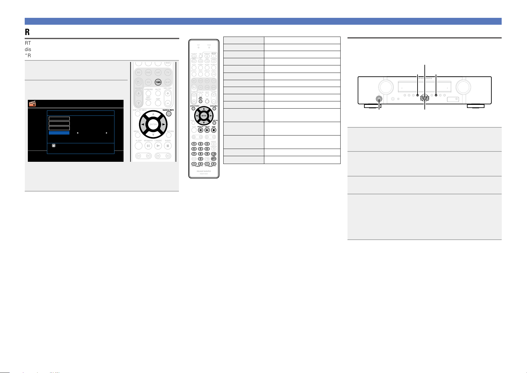
RT (Radio Text)
RT allows RDS stations to send text messages that appear on the
display.
“RT” appears on the display when radio text data is received.
1
Press TUNER twice to switch the
input source to “TUNER”.
2
Press SEARCH/INFO to select
“RT”.
TUNER
[
MEMORY
]
Band
Memory
[
T.MODE
] Mode[BAND]
[
PRESET+/-
] Preset
Tuning[
TUNING+/-
]
[
SEARCH
] Search
RDS
RDS station
Program category
Traffic info
ON
RDS
PTY
TP
RT
[
SEARCH
]SearchMode
FM 90.10MHz
•While receiving an RDS broadcast station, the text data broadcast
from the station is displayed.
•To turn the display off, press o p.
•If no text data is being broadcast, “NO TEXT DATA” is displayed.
Tuning in radio stations
n Tuner (FM/AM) operation
Operation buttons Function
AMP MENU Amp menu
SHIFT/TOP MENU Preset channel block selection
SEARCH/INFO Direct frequency tuning / RDS Search
uio p
Cursor operation
ENTER Enter
RETURN Return
MEMORY Preset memory registration
T.MODE Switch search modes
BAND FM/AM switching
0 – 9
Preset channel selection (1 – 8) /
Direct frequency tuning (0 – 9)
TV Z / X
TV power on/standby
(Default : marantz)
TV INPUT
Switch TV input
(Default : marantz)
TUNING +, – Tuning (up/down)
PRESET +, – Preset channel selection
Switching the tuning increment
The tuning increment factory settings are 9 kHz for AM, and 0.05 MHz
for FM.
o p
MENU
BAND
ENTER
ON/STANDBY
1
While pressing down MENU and BAND, press ON/
STANDBY
to turn on the power.
“AM9/FM50” appears on the display.
2
Press o p.
“AM10/FM200” appears on the display, and the tuning
increment is switched to AM and FM are 10 kHz and 0.2 MHz.
3
Press ENTER.
4
Press ON/STANDBY.
•The tuner preset memory will be cleared if this operation is
performed.
•This setting will not revert to the default values even when the
microprocessor is reset.
Basic version
Advanced version
Information
Basic version
BD
24
Selecting a listening mode (Surround mode)
This unit can play input audio signals in multi-channel surround mode or in stereo mode.
Select a listening mode suitable for the playback contents (movie, music, etc.) or according to your liking.
Selecting a listening mode
1
Play the selected device
(vpage 19).
2
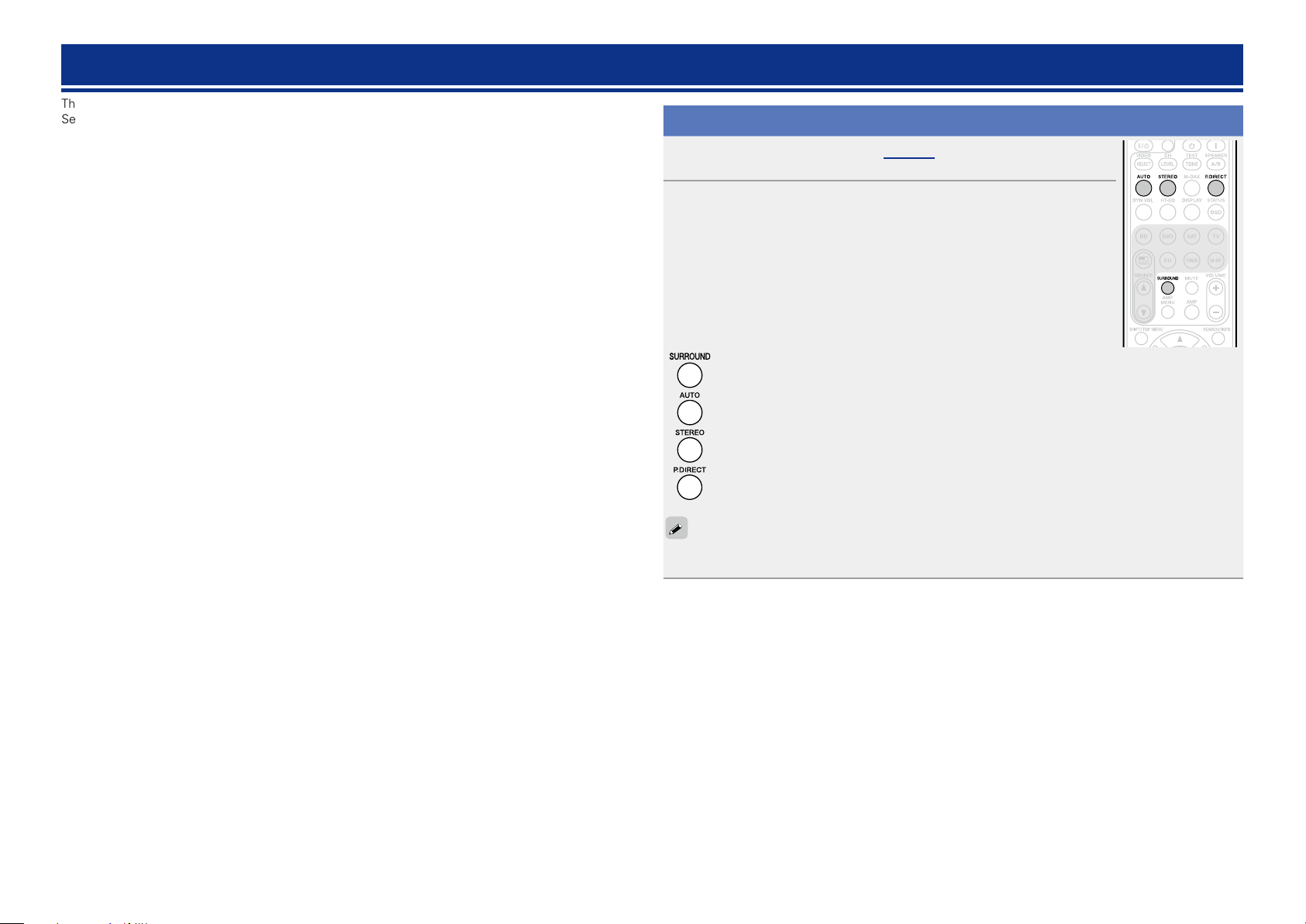
Press SURROUND, AUTO, STEREO or P.DIRECT to select a
listening mode.
•Each time SURROUND, AUTO, STEREO or P.DIRECT is pressed, the listening
mode is switched.
Various types of surround sound can be selected to match the source being played back. Press
SURROUND until the desired surround mode is reached.
This mode detects the type of input digital signal, and automatically selects the corresponding
mode for playback.
Switches the listening mode to Stereo mode.
Switches the listening mode to DIRECT or PURE DIRECT mode. In DIRECT mode, the audio is
played back exactly how it was recorded.
When PURE DIRECT mode is selected, the PURE DIRECT indicator on the unit lights.
The listening mode can also be selected in the same way for the SURROUND MODE, AUTO and PURE
DIRECT
on the main unit.
Basic version
Advanced version
Information
Basic version
vSee overleaf
25
Selecting a listening mode
n Listening mode
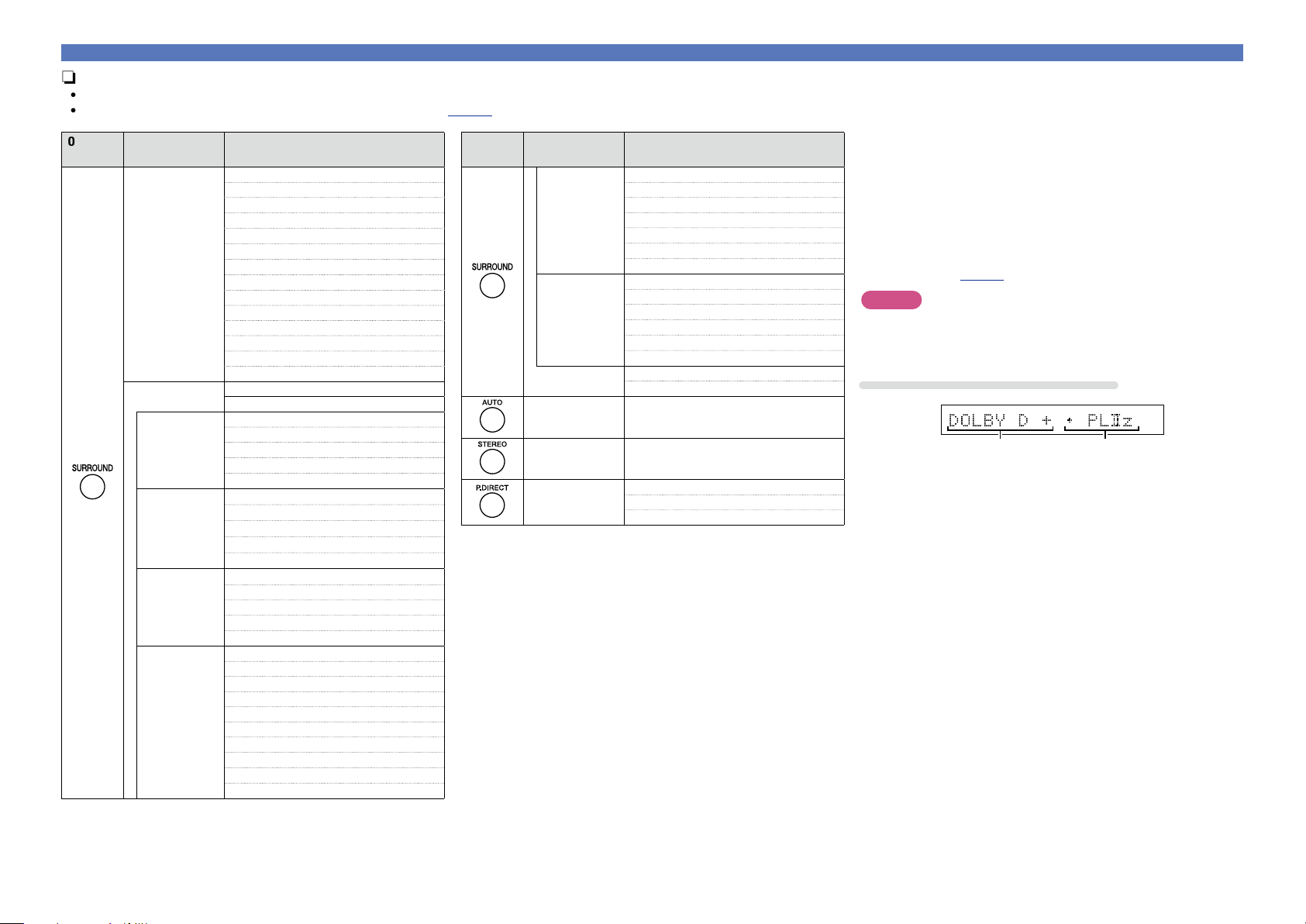
•The following listening modes can be selected using the SURROUND, AUTO, STEREO and P.DIRECT buttons.
•Adjust the sound field effect with the menu “Surr.Parameter” (vpage49) to enjoy your favorite sound mode.
Operation
button
Input signal Listening mode
2-channel
z1
AUTO
z2
STEREO
DOLBY PLgx Movie
z3
DOLBY PLg Movie
z3
DOLBY PLgx Music
z3
DOLBY PLg Music
z3
DOLBY PLgx Game
z3
DOLBY PLg Game
z3
DOLBY Pro Logic
z3
DTS NEO:6 Cinema
z3
DTS NEO:6 Music
z3
DOLBY PLgz Height
z3
MULTI CH STEREO
VIRTUAL
Multi-channel
z4
AUTO
z2
STEREO
Dolby Digital
DOLBY DIGITAL
DOLBY DIGITAL EX
DOLBY DIGITAL + PLgx Movie
DOLBY DIGITAL + PLgx Music
DOLBY DIGITAL + PLgz
Dolby TrueHD
DOLBY TrueHD
DOLBY TrueHD + EX
DOLBY TrueHD + PLgx Movie
DOLBY TrueHD + PLgx Music
DOLBY TrueHD + PLgz
Dolby Digital
Plus
DOLBY DIGITAL Plus
DOLBY DIGITAL Plus + EX
DOLBY DIGITAL Plus + PLgx Movie
DOLBY DIGITAL Plus + PLgx Music
DOLBY DIGITAL Plus + PLgz
DTS
DTS SURROUND
DTS ES DSCRT 6.1
DTS ES MTRX 6.1
DTS 96/24
DTS 96 ES MTRX
DTS ES DSCRT
DTS + NEO:6
DTS + PLgx Movie
DTS + PLgx Music
DTS + PLgz
Operation
button
Input signal Listening mode
DTS-HD /
DTS Express
DTS-HD HI RES
DTS-HD MSTR
DTS Express
DTS-HD + NEO:6
DTS-HD + PLgx Movie
DTS-HD + PLgx Music
DTS-HD + PLgz
PCM multi-
channel
MULTI CH IN
MULTI CH IN 7.1
MULTI IN + Dolby EX
MULTI IN + PLgx Movie
MULTI IN + PLgx Music
MULTI IN + PLgz
Multi-channel
z4
MULTI CH STEREO
VIRTUAL
All AUTO
z2
All STEREO
All
DIRECT
PURE DIRECT
AUTO
z2
z1 2-channel also includes analog input.
z2 When AUTO mode is selected, the surround mode that is
compatible with the input signal is used for playback.
z3 This mode plays back 2-channel source in 5.1 or 7.1-channel
playback. It cannot be selected when headphones are used, or
when only front speakers are used.
z4 Some listening modes cannot be selected, depending on the
audio format or number of channels of the input signal. For
details, see “Types of input signals, and corresponding surround
modes” (vpage82).
NOTE
When you use headphones, you can choose the VIRTUAL, STEREO,
DIRECT and PURE DIRECT mode.
Views on the TV screen or display
q w
q Shows a decoder to be used.
•A DOLBY DIGITAL Plus decoder is displayed as “DOLBY D +”.
w Shows a decoder that creates sound output from the surround
back speakers.
•“+ PLgz” indicates the front height sound from front height
speakers.
Basic version
Advanced version
Information
Basic version
vSee overleaf
26
Selecting a listening mode
n Description of listening mode types
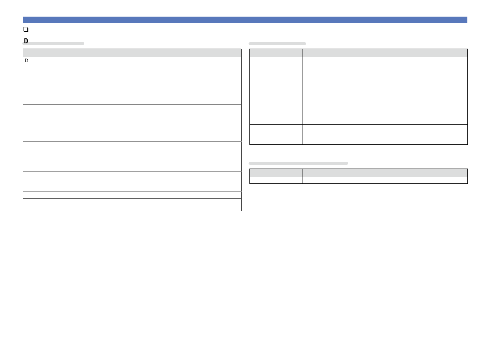
Dolby listening mode
Listening mode type Description
DOLBY PLgx
z1
This mode can be selected when a Dolby Pro Logic gx decoder is used to
play back 2-channel source in 6.1/7.1-channel surround sound including the
surround back channel.
By adding the surround back channel, a stronger surround feeling is obtained
compared to Dolby Pro Logic g.
There are three playback modes: “Movie” mode that is optimized for movie
playback, “Music” mode that is optimized for music playback, and “Game”
mode that is optimized for game play.
DOLBY PLg This mode can be selected when a Dolby Pro Logic g decoder is used to play
back 2-channel source in 5.1-channel surround sound with a natural, realistic
feel.
DOLBY Pro Logic This mode can be selected when a DOLBY Pro Logic decoder is used to play
2-channel source in 4.1-channel surround sound (Left/Center/Right/Surround
Mono).
DOLBY PLgz
z2
This mode can be selected when a Dolby Pro Logic gz decoder is used to play
back 2-channel source in 7.1-channel surround sound with added front height
channel.
By adding a front height channel, the vertical expression is emphasized,
improving the three-dimensionality of the sound.
DOLBY DIGITAL This mode can be selected when playing sources recorded with Dolby Digital.
DOLBY DIGITAL EX
z1
This mode improves the depth, dimension, and expressiveness of the sound
stage by sound field playback including surround back channels.
DOLBY TrueHD This mode can be selected when playing sources recorded in Dolby TrueHD.
DOLBY DIGITAL Plus This mode can be selected when playing sources recorded with Dolby Digital
Plus.
z1 This can be selected when “Speaker Config.” – “S.Back” is not set to “None”.
z2 This can be selected when “Speaker Config.” – “F.Height” is not set to “None”.
DTS listening mode
Listening mode type Description
DTS NEO:6 This mode can be selected when a DTS NEO:6 decoder is used to play back
2-channel source in 6.1/7.1-channel surround sound including the surround
back channel.
There is a “Cinema” mode optimized for movie playback, and a “Music” mode
optimized for music playback.
DTS SURROUND This mode can be selected when playing sources recorded in DTS.
DTS ES DSCRT6.1
z
This mode can be selected when playing sources recorded in DTS-ES.
Provides optimum playback of DTS-ES Discrete signals using surround back.
DTS ES MTRX6.1
z
This mode can be selected when playing sources recorded in DTS-ES.
Surround back channel data encoded in DTS-ES Matrix recording software is
played from the surround back channel.
DTS 96/24 This mode can be selected when playing sources recorded in DTS 96/24.
DTS-HD This mode can be selected when playing sources recorded in DTS-HD.
DTS Express This mode can be selected when playing sources recorded in DTS Express.
z This can be selected when “Speaker Config.” – “S.Back” is not set to “None”.
PCM multi-channel listening mode
Listening mode type Description
MULTI CH IN This mode can be selected when playing multi-channel PCM sources .
Basic version
Advanced version
Information
Basic version
vSee overleaf
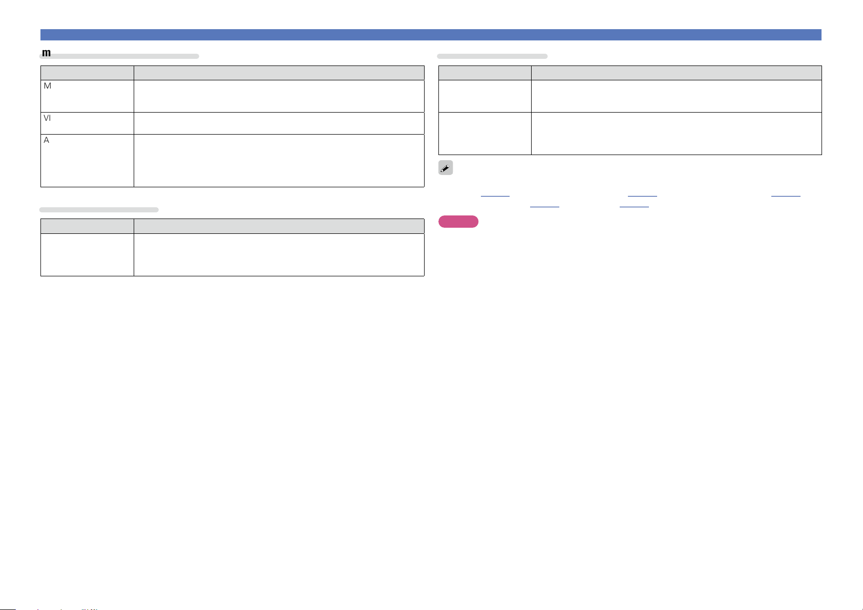
27
Selecting a listening mode
marantz original listening mode
Listening mode type Description
MULTI CH STEREO This mode is for enjoying stereo sound from all speakers.
The same sound as that from the front speakers (L/R) is played back at the
same level from the surround speakers (L/R) and surround back speakers (L/R).
VIRTUAL This mode is for enjoying surround effects using only the front speakers or
headphones.
AUTO In this mode, the type of digital signal input, such as Dolby Digital, Dolby
TrueHD, Dolby Digital Plus, Dolby Digital EX, DTS, DTS-HD, DTS-ES, PCM
(multi-channel) is detected, and the playback mode switches automatically to
the corresponding mode.
If the input signal is analog or PCM (2-channel), stereo playback is used.
STEREO listening mode
Listening mode type Description
STEREO This is the mode for playing in stereo. The tone can be adjusted.
•Sound is output from the front left and right speakers and subwoofer.
•If multichannel signals are input, they are mixed down to 2-channel audio and
are played.
Direct listening mode
Listening mode type Description
DIRECT This mode plays back tracks at high sound quality without passing through the
sound quality adjustment circuits.
•Surround back signals or front height signals are not created.
PURE DIRECT This mode plays back tracks at the closest to the original sound quality.
Turn the display of the amplifier off to stop the analogue video circuit. This
suppresses the source of noise that affects sound quality.
•Surround back signals or front height signals are not created.
In Direct listening mode, the following items cannot be adjusted.
•Tone (vpage50) •MultEQ
®
(vpage50) •Dynamic EQ
®
(vpage51)
•Dynamic Volume
®
(
vpage51
)
•M-DAX (vpage52)
NOTE
•Video signals are only output when HDMI signals are played in the PURE DIRECT mode.
•When in the PURE DIRECT mode, the menu screen is not displayed.
Basic version
Advanced version
Information
Basic version
Loading...