


 Loading...
 Manitowoc
S Model
Ice Machines
Technician’s
Handbook
This manual is updated as new information and models are released. Visit our website for the latest manual. www.manitowocice.com
America’s #1 Selling Ice Machine
Part Number 80-1479-3 7/10
Safety Notices
As you work on Manitowoc equipment, be sure to pay close attention to the safety notices in this handbook. Disregarding the notices may lead to serious injury and/or damage to the equipment.
Throughout this handbook, you will see the following types of safety notices:
|
! Warning |
|
|
|
Text in a |
Warning b ox alerts yo u to a |
p otential |
|
|
personal |
injury si tuation. |
Be su re to |
read the |
|
Warning statement before |
proceeding, and work |
|||
carefully. |
|
|
|
|
|
|
|
|
|
! Caution
Text in a Caution box alerts you to a si tuation in which you could damage the equipment. Be sure to read the Caution statement before proceeding, and work carefully.
Procedural Notices
As you work on Manitowoc equipment, be sure to read the procedural notices in this handbook. These notices supply helpful information which may assist you as you work.
Throughout this handbook, you will see the following types of procedural notices:
|
|
Important |
|
|
|
|
|
Text in an |
Impo rtant |
b ox |
provid es |
you wi |
th |
||
information |
t hat |
ma y |
h elp |
yo u |
perform |
a |
|
procedure more |
ef ficiently. |
Di |
sregarding thi |
s |
|||
information will not cause damage or injury, but it |
|
||||||
may slow you down as you work. |
|
|
|
|
|||
|
|
|
|
|
|
|
|

NOTE: Text set off as a Note provides you with simple, but useful, extra information about the procedure you are performing.
Read These Before Proceeding:
|
|
! |
Caution |
|
|
|
|
|
||
Proper i nstallation, |
ca re |
and |
ma intenance |
are |
|
|
||||
essential for maximum performance |
and trouble- |
|
|
|||||||
free op eration of you r Manitowo c eq uipment. If |
|
|
||||||||
you en counter prob lems not covered |
by |
|
this |
|||||||
handbook, do no t procee d, |
contact Ma nitowoc |
|
|
|||||||
Foodservice. |
We |
wi ll |
b e |
happy |
to p |
|
rovide |
|||
assistance. |
|
|
|
|
|
|
|
|
|
|
|
|
|
|
|
|
|
|
|
||
|
|
|
|
|
|
|
|
|
||
|
|
Important |
|
|
|
|
|
|
||
Routine |
ad |
justments |
and |
|
main |
|
tenance |
|||
procedures |
outlin ed |
in thi s |
handbook |
are |
not |
|
||||
covered by the warranty. |
|
|
|
|
|
|
|
|||
|
|
|
|
|
|
|
|
|
||
|
|
|
|
|
|
|
|
|
||
|
|
! |
Warning |
|
|
|
|
|
||
PERSONAL INJURY POTENTIAL |
|
|
|
|||||||
Do n ot |
ope |
rate |
eq |
uipment |
that |
has |
b |
|
een |
|
misused, |
ab |
used, |
ne |
glected, |
d amaged, |
o |
r |
|||
altered/modified from that of original |
|
|
||||||||
manufactured specifications. |
|
|
|
|
|
|
||||
|
|
|
|
|
|
|
|
|
|
|
We reserve the right to make product improvements at any time. Specifications and design are subject to change without notice.

Table of Contents
General Information
Model Numbers . . . . . . . . . . . . . . . . . . . . . 9 How to Read a Model Number . . . . . . 10
Ice Cube Sizes . . . . . . . . . . . . . . . . . . . . . 10
Model/Serial Number Location . . . . . . . . 11
Energy Efficient Ice Machine
Serial Breaks . . . . . . . . . . . . . . . . . . . . . . . 12
Ice Machine Warranty Information . . . . . 13 Owner Warranty Registration Card . . . 13 Commercial Warranty Coverage . . . . . 14 Residential Ice Machine Warranty . . . . 16
Installation
Location of Ice Machine . . . . . . . . . . . . . . 21 Ice Machine Clearance Requirements . . 22 Ice Machine Heat of Rejection . . . . . . . . . 23
Remote Condenser Line Set Installation
. . . . . . . . . . . . . . . . . . . . . . . . . . . . . . . 24 Calculating Remote Condenser Installation Distances . . . . . . . . . . . . . 25 Lengthening or Reducing Line Sets . . 27 Connecting A Line Set . . . . . . . . . . . . 28
Component Identification
S Model Single Evaporator Models . . . . . 29 S Model Quad Evaporator Models . . . . . 30
Maintenance
General . . . . . . . . . . . . . . . . . . . . . . . . . . . 31
Cleaning / Sanitizing Procedure . . . . . . . 32 Cleaning Procedure . . . . . . . . . . . . . . 32 Parts Removal for Cleaning/Sanitizing 34
Procedure to Clean Heavily Scaled
Ice Machines . . . . . . . . . . . . . . . . . . . . . . . 40 General . . . . . . . . . . . . . . . . . . . . . . . . 40 Cleaning Procedure . . . . . . . . . . . . . . 40 Parts Removal for Cleaning/Sanitizing 43
Part Number 80-1479-3 7/10 |
5 |
Removal from Service/Winterization . . . 57 Self-Contained Air-Cooled Ice Machines 57 Water-Cooled Ice Machines . . . . . . . . 58 Remote Ice Machines . . . . . . . . . . . . . 58
Sequence of Operation
Self Contained Air or Water Cooled . . . . 59 Single & Quad Evaporator Models . . . 59 Safety Timers . . . . . . . . . . . . . . . . . . . . . . 64 Safety Limits . . . . . . . . . . . . . . . . . . . . . . 65 Remotes . . . . . . . . . . . . . . . . . . . . . . . 72
Troubleshooting
Safety Limits . . . . . . . . . . . . . . . . . . . . . . 81 Quad Evaporator Machines Only . . . . 82 Analyzing Why a Safety Limit Stopped the Ice Machine . . . . . . . . . . . . . . . . . . . . 84 Safety Limit #1 . . . . . . . . . . . . . . . . . . 85 Safety Limit #2 . . . . . . . . . . . . . . . . . . 86 Safety Limit #3 . . . . . . . . . . . . . . . . . . 87
Control Board Testing . . . . . . . . . . . . . . . 88 Control Board Test Cycle . . . . . . . . . . 88
Troubleshooting By Symptom . . . . . . . . 89 Symptom #1 Ice Machine will not run . 90 Compressor Electrical Diagnostics . . . 92 Symptom #2 Low Productionand/or Long Freeze Cycle . . . . . . . . . . . . . . . . . . . . 94 Symptom #2 - Freeze Cycle Refrigeration System Operational Analysis Tables . 96 Freeze Cycle Refrigeration System Operational Analysis Table Procedures . . . . 105
Harvest Problems . . . . . . . . . . . . . . . . . . 126 Symptom #3 Ice Will Not Harvest, Cubes Are Not Melted . . . . . . . . . . . . . . . . . . 127 Symptom #3 - Traditional Remotes Only
. . . . . . . . . . . . . . . . . . . . . . . . . . . . . . 129 Symptom #4 Will Not Harvest, Cubes Are Melted . . . . . . . . . . . . . . . . . . . . . . . . . 131
6 |
Part Number 80-1479-3 7/10 |
Component Check Procedures
Electrical Components . . . . . . . . . . . . . . . 135 Main Fuse . . . . . . . . . . . . . . . . . . . . . . 135 ICE/OFF/CLEAN Toggle Switch . . . . . 136 Bin Switch . . . . . . . . . . . . . . . . . . . . . . 137 Cleaning the Ice Thickness or Water Level Probe . . . . . . . . . . . . . . . . . . . . . . . . . . 140 Water Level Control Circuitry . . . . . . . 141 Ice Thickness Probe (Harvest Initiation)
. . . . . . . . . . . . . . . . . . . . . . . . . . . . . . . 146 Harvest Assist Air Pump . . . . . . . . . . . 151
Compressor Electrical Diagnostics . . . . 152 Diagnosing Start Components . . . . . . 154
Refrigeration Components . . . . . . . . . . . 158 High Pressure Cutout (HPCO) Control 158 Fan Cycle Control . . . . . . . . . . . . . . . . 159 Water Regulating Valve . . . . . . . . . . . 160 Harvest Pressure Regulating (HPR) System Remotes Only . . . . . . . . . . . . . . . . . . . 161 Head Pressure Control Valve . . . . . . . 164 Low Pressure Cutout (LPCO) Control . 167 Harvest Pressure Solenoid Valve . . . . 168
Refrigerant Recovery/Evacuation . . . . . . 169 Normal Self-Contained Model Procedures
. . . . . . . . . . . . . . . . . . . . . . . . . . . . . . . 169 Normal Remote Model Procedures . . . 173
System Contamination Clean-Up . . . . . . 178 Determining Severity Of Contamination 178 Cleanup Procedure . . . . . . . . . . . . . . . 180 Replacing Pressure Controls Without Removing Refrigerant Charge . . . . . . . . . 183
Specifications
Main Fuse . . . . . . . . . . . . . . . . . . . . . . 185 Fan Cycle Control . . . . . . . . . . . . . . . . 185 High Pressure Cutout (HPCO) Control 185 Filter-Driers . . . . . . . . . . . . . . . . . . . . . 186 Total System Refrigerant Charge . . . . 187
Part Number 80-1479-3 7/10 |
7 |
Charts
Cycle Times/24-Hour Ice Production/ Refrigerant Pressure Charts . . . . . . . . . . 191
S300 Series . . . . . . . . . . . . . . . . . . . . 192 S320 Series . . . . . . . . . . . . . . . . . . . . 196 S420 Series . . . . . . . . . . . . . . . . . . . . 198 S450 Series . . . . . . . . . . . . . . . . . . . . 202 S500 Series . . . . . . . . . . . . . . . . . . . . 206 S600 Series . . . . . . . . . . . . . . . . . . . . 215 S850 Series . . . . . . . . . . . . . . . . . . . . 218 S1000 Series . . . . . . . . . . . . . . . . . . . 227 S1200 Series . . . . . . . . . . . . . . . . . . . 236 S1400 Series . . . . . . . . . . . . . . . . . . . 242 S1600 Series . . . . . . . . . . . . . . . . . . . 253 S1800 Series . . . . . . . . . . . . . . . . . . . 256 S3300 Series . . . . . . . . . . . . . . . . . . . 265
Diagrams
Wiring Diagrams . . . . . . . . . . . . . . . . . . . 267 Wiring Diagram Legend . . . . . . . . . . . 267 Wiring Diagrams Before Energy Efficient & EnergyStar Machines . . . . . . . . . . . . . 268 Wiring Diagrams for Energy Efficient & EnergyStar Machines . . . . . . . . . . . . . . . 279
Electronic Control Board . . . . . . . . . . . . 290 Single and Twin Evaporator . . . . . . . . 290 Single and Twin Evaporator With Test Button . . . . . . . . . . . . . . . . . . . . . . . . . . . 291 Quad Evaporator Ice Machines . . . . . 292
Refrigeration Tubing Schematics . . . . . 293 Self-Contained Airor
Water -Cooled Models . . . . . . . . . . . . 293 Remote Models . . . . . . . . . . . . . . . . . 295
8 |
Part Number 80-1479-3 7/10 |

General Information
Model Numbers
This manual covers the following models:
Self-Contained |
Self-Contained |
Remote |
|
Air-Cooled |
Water-Cooled |
||
|
|||
SD0302A |
SD0303W |
--- |
|
SY0304A |
SY0305W |
--- |
|
|
|
|
|
SD0322A |
SD0323W |
--- |
|
SY0324A |
SY0325W |
--- |
|
|
|
|
|
SR0420A |
SR0421W |
--- |
|
SD0422A |
SD0423W |
--- |
|
SY0424A |
SY0425W |
|
|
|
|
|
|
SD0452A |
SD0453W |
--- |
|
SY0454A |
SY0455W |
--- |
|
|
|
|
|
SR0500A |
SR0501W |
SD0592N |
|
SD0502A |
SD0503W |
SY0594N |
|
SY0504A |
SY0505W |
|
|
|
|
|
|
SD0602A |
SD0603W |
SD0692N |
|
SY0604A |
SY0605W |
SY0694N |
|
|
|
|
|
SR0850A |
SR0851W |
SR0890N |
|
SD0852A |
SD0853W |
SD0892N |
|
SY0854A |
SY0855W |
SY0894N |
|
|
|
|
|
SR1000A |
SR1001W |
SR1090N |
|
SD1002A |
SD1003W |
SD1092N |
|
SY1004A |
SY1005W |
SY1094N |
|
|
|
|
|
SD1202A |
SD1203W |
--- |
|
SY1204A |
SY1205W |
--- |
|
|
|
|
|
SD1402A |
SD1403W |
SD1492N |
|
SY1404A |
SY1405W |
SY1494N |
|
|
|
|
|
SR1600A |
SR1601W |
SR1690N |
|
SD1602A |
SD1603W |
SD1692N |
|
SY1604A |
SY1605W |
SY1694N |
|
|
|
|
|
SR1800A |
SR1801W |
SR1890N |
|
SD1802A |
SD1803W |
SD1892N |
|
SY1804A |
SY1805W |
SY1894N |
|
|
|
|
|
--- |
SD3303W |
--- |
|
--- |
SD3303WHP |
--- |
|
--- |
SY3305W |
--- |
|
--- |
SY3305WHP |
--- |
NOTE: Model numbers ending in 3 indicate a 3 phase unit. Example: SY1004A3.
Part Number 80-1479-3 7/10 |
9 |
HOW TO READ A MODEL NUMBER
|
# |
CUBE SIZE |
CONDENSER TYPE |
|
0 |
REGULAR |
AIR-COOLED |
9 REMOTE |
1 |
REGULAR |
WATER-COOLED |
AIR-COOLED |
2 |
DICE |
AIR-COOLED |
|
3 |
DICE |
WATER-COOLED |
|
4 |
HALF-DICE |
AIR-COOLED |
|
5 |
HALF-DICE |
WATER-COOLED |
S Y 1094 N SI
|
|
|
ADDITIONAL SPECS |
|
ICE MACHINE |
|
3 |
PHASE |
|
ICE MACHINE |
M |
MARINE UNIT |
||
MODEL |
SERIES |
HP HIGH PRESSURE |
||
|
|
|
SI |
WATER VALVE |
ICE CUBE SIZE |
|
AUCS-SI INCLUDED |
||
|
|
|
||
R |
REGULAR |
CONDENSER TYPE |
|
|
D |
DICE |
A SELF-CONTAINED AIR-COOLED |
||
Y |
HALF DICE |
|||
|
|
W SELF-CONTAINED WATER-COOLED |
||
N REMOTE AIR-COOLED
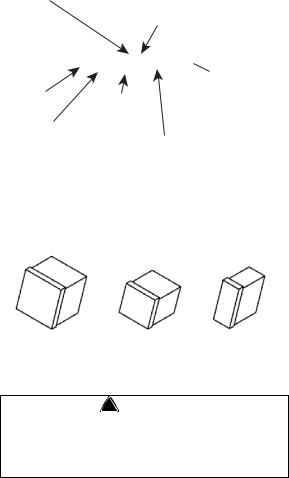
Ice Cube Sizes
Regular |
Dice |
Half Dice |
1-1/8" x 1-1/8" x 7/8" |
7/8" x 7/8" x 7/8" |
3/8" x 1-1/8" x 7/8" |
2.86 x 2.86 x 2.22 cm |
2.22 x 2.22 x2.22 cm |
0.95 x 2.86 x 2.22 cm |
! Warning
Personal Injury Potential
Do not operate equipment that has been misused, abused, neglected, damaged, or altered/modified from that of original manufactured specifications.
10 |
Part Number 80-1479-3 7/10 |
! Warning
All Man itowoc ice ma chines re quire th e ice storage system (bin, dispenser, etc.) to incorporate an ice deflector.
48” w ide |
S |
Model ice mach ines re quire add ing |
||||||||||
Manitowoc |
Ice |
Deflector |
Kit |
K00 |
|
349 |
w |
hen |
||||
installing |
|
wi |
th |
|
non-Manitowoc |
|
ice |
sto |
|
rag |
||
systems. |
|
|
|
|
|
|
|
|
|
|
|
|
30” w ide |
S |
Model ice mach ines re quire add ing |
||||||||||
Manitowoc |
Ice |
Deflector |
Kit |
K00 |
|
347 |
w |
hen |
||||
installing |
|
wi |
th |
|
non-Manitowoc |
|
ice |
sto |
|
rag |
||
systems. |
|
|
|
|
|
|
|
|
|
|
|
|
Prior to |
|
using |
a |
non -Manitowoc |
ice sto |
rage |
||||||
system |
with |
other |
Manitowoc |
ice machin |
|
es, |
||||||
contact |
th e |
manufacturer |
to assu |
|
re |
th eir |
ice |
|||||
deflector |
|
is |
comp |
atible |
wi |
th |
Mani |
towoc |
ice |
|||
machines. |
|
|
|
|
|
|
|
|
|
|
|
|
Model/Serial Number Location
These numbers are required when requesting information from your local Manitowoc Distributor, service representative, or Manitowoc Ice, Inc. The model and serial number are listed on the OWNER WARRANTY REGISTRATION CARD. They are also listed on the MODEL/SERIAL NUMBER DECAL affixed to the ice machine.
Part Number 80-1479-3 7/10 |
11 |
Energy Efficient Ice Machine Serial Breaks
Some specifications have changed with our release of more Energy Efficient machines. The following machines have a serial break to indicate when they became more Energy Efficient.
Series Ice |
Serial Break/Manufacture Date for |
|
Machine |
Energy Efficient Machines |
|
|
|
|
S300 |
110704351 |
|
|
|
|
S420 |
110667970 |
|
|
|
|
S450 |
110670157 |
|
|
|
|
S500 |
110684316 |
|
|
|
|
S850 |
110683282 |
|
|
|
|
S1000 |
110697023 |
|
|
|
|
S1200 |
110707329 |
|
|
|
|
S1400W |
Manufacture Date After 0711 |
|
(November 2007) |
||
|
||
|
|
|
|
Manufacture Date Between |
|
S1400W |
0711 & 0905 |
|
|
(November 2007 & May 2009) |
|
|
|
|
S1400A |
Manufacture Date After 0905 |
|
S1400W |
||
(May 2009) |
||
S1400N |
||
|
||
|
|
|
S1800A |
Manufacture Date After 0910 |
|
S1800W |
||
(October 2009) |
||
S1800N |
||
|
||
|
|
12 |
Part Number 80-1479-3 7/10 |
Ice Machine Warranty Information
OWNER WARRANTY REGISTRATION CARD
Warranty coverage begins the day the ice machine is installed.
|
Important |
|
|
|
Complete and |
mailthe |
OW NER |
WARRANTY |
|
REGISTRATION |
C ARD |
as soon |
as p ossible |
to |
validate the installation date. |
|
|
||
|
|
|
|
|
If the OWNER WARRANTY REGISTRATION CARD is not returned, Manitowoc will use the date of sale to the Manitowoc Distributor as the first day of warranty coverage for your new ice machine.
Part Number 80-1479-3 7/10 |
13 |
COMMERCIAL WARRANTY COVERAGE
Manitowoc Ice, (hereinafter referred to as the "COMPANY") warrants for a period of thirty-six months from the installation date (except as limited below) that new ice machines manufactured by the COMPANY shall be free of defects in material or workmanship under normal and proper use and maintenance as specified by the COMPANY and upon proper installation and start-up in accordance with the instruction manual supplied with the ice machine.
The COMPANY'S warranty hereunder with respect to the compressor shall apply for an additional twentyfour months, excluding all labor charges, and with respect to the evaporator for an additional twenty-four months, including labor charges.
The obligation of the COMPANY under this warranty is limited to the repair or replacement of parts, components, or assemblies that in the opinion of the COMPANY are defective. This warranty is further limited to the cost of parts, components or assemblies and standard straight time labor charges at the servicing location. Time and hourly rate schedules, as published from time to time by the COMPANY, apply to all service procedures.
Additional expenses including without limitation, travel time, overtime premium, material cost, accessing or removal of the ice machine, or shipping are the responsibility of the owner, along with all maintenance, adjustments, cleaning, and ice purchases.
Labor covered under this warranty must be performed by a COMPANY Contracted Service Representative or a refrigeration service agency as qualified and authorized by the COMPANY'S local Distributor.
The COMPANY'S liability under this warranty shall in no event be greater than the actual purchase price paid by customer for the ice machine.
14 |
Part Number 80-1479-3 7/10 |
The foregoing warranty shall not apply to (1) any part or assembly that has been altered, modified, or changed; (2) any part or assembly that has been subjected to misuse, abuse, neglect, or accidents; (3) any ice machine that has been installed and/or maintained inconsistent with the technical instructions provided by the COMPANY; or (4) any ice machine initially installed more than five years from the serial number production date. This warranty shall not apply if the Ice Machine's refrigeration system is modified with a condenser, heat reclaim device, or parts and assemblies other than those manufactured by the COMPANY, unless the COMPANY approves these modifications for specific locations in writing.
THIS WARRANTY IS IN LIEU OF ALL OTHER WARRANTIES OR GUARANTEES OF ANY
KIND, EXPRESSED OR IMPLIED, INCLUDING ANY IMPLIED WARRANTY OF MERCHANTABILITY
OR FITNESS FOR A PARTICULAR PURPOSE.
In no event shall the COMPANY be liable for any special, indirect, incidental or consequential damages. Upon the expiration of the warranty period, the COMPANY'S liability under this warranty shall terminate. The foregoing warranty shall constitute the sole liability of the COMPANY and the exclusive remedy of the customer or user.
To secure prompt and continuing warranty service, the warranty registration card must be completed and sent to the COMPANY within five (5) days from the installation date.
To obtain warranty service or information regarding your Product, please contact us at:
MANITOWOC ICE
2110 So. 26th St. P.O. Box 1720, Manitowoc, WI 54221-1720
Telephone: 920-682-0161 Fax: 920-683-7585 www.manitowocice.com
Part Number 80-1479-3 7/10 |
15 |
RESIDENTIAL ICE MACHINE LIMITED WARRANTY
WHAT DOES THIS LIMITED WARRANTY COVER?
Subject to the exclusions and limitations below, Manitowoc Ice, Inc. (“Manitowoc”) warrants to the original consumer that any new ice machine manufactured by Manitowoc (the “Product”) shall be free of defects in material or workmanship for the warranty period outlined below under normal use and maintenance, and upon proper installation and startup in accordance with the instruction manual supplied with the Product.
HOW LONG DOES THIS LIMITED WARRANTY LAST?
Product Covered |
Warranty Period |
|
|
|
|
Ice Machine |
Twelve months from the |
|
sale date |
||
|
||
|
|
WHO IS COVERED BY THIS LIMITED WARRANTY?
This limited warranty only applies to the original consumer of the Product and is not transferable.
16 |
Part Number 80-1479-3 7/10 |
WHAT ARE MANITOWOC ICE’S OBLIGATIONS UNDER THIS LIMITED WARRANTY?
If a defect arises and Manitowoc receives a valid warranty claim prior to the expiration of the warranty period, Manitowoc shall, at its option: (1) repair the Product at Manitowoc’s cost, including standard straight time labor charges, (2) replace the Product with one that is new or at least as functionally equivalent as the original, or (3) refund the purchase price for the Product. Replacement parts are warranted for 90 days or the balance of the original warranty period, whichever is longer. The foregoing constitutes Manitowoc’s sole obligation and the consumer’s exclusive remedy for any breach of this limited warranty. Manitowoc’s liability under this limited warranty is limited to the purchase price of Product. Additional expenses including, without limitation, service travel time, overtime or premium labor charges, accessing or removing the Product, or shipping are the responsibility of the consumer.
HOW TO OBTAIN WARRANTY SERVICE
To obtain warranty service or information regarding your Product, please contact us at:
MANITOWOC ICE
2110 So. 26th St.
P.O. Box 1720, Manitowoc, WI 54221-1720
Telephone: 920-682-0161 Fax: 920-683-7585 www.manitowocice.com
Part Number 80-1479-3 7/10 |
17 |
WHAT IS NOT COVERED?
This limited warranty does not cover, and you are solely responsible for the costs of: (1) periodic or routine maintenance, (2) repair or replacement of the Product or parts due to normal wear and tear, (3) defects or damage to the Product or parts resulting from misuse, abuse, neglect, or accidents, (4) defects or damage to the Product or parts resulting from improper or unauthorized alterations, modifications, or changes; and (5) defects or damage to any Product that has not been installed and/or maintained in accordance with the instruction manual or technical instructions provided by Manitowoc. To the extent that warranty exclusions are not permitted under some state laws, these exclusions may not apply to you.
EXCEPT AS STATED IN THE FOLLOWING SENTENCE, THIS LIMITED WARRANTY IS THE SOLE AND EXCLUSIVE WARRANTY OF MANITOWOC WITH REGARD TO THE PRODUCT. ALL IMPLIED WARRANTIES ARE STRICTLY LIMITED TO THE DURATION OF THE LIMITED WARRANTY APPLICABLE TO THE PRODUCTS AS STATED ABOVE, INCLUDING BUT NOT LIMITED TO, ANY WARRANTY OF MERCHANTABILITY OR OF FITNESS FOR A PARTICULAR PURPOSE.
Some states do not allow limitations on how long an implied warranty lasts, so the above limitation may not apply to you.
18 |
Part Number 80-1479-3 7/10 |
IN NO EVENT SHALL MANITOWOC OR ANY OF ITS AFFILIATES BE LIABLE TO THE CONSUMER OR ANY OTHER PERSON FOR ANY INCIDENTAL, CONSEQUENTIAL OR SPECIAL DAMAGES OF ANY KIND (INCLUDING, WITHOUT LIMITATION, LOSS OF PROFITS, REVENUE OR BUSINESS) ARISING FROM OR IN ANY MANNER CONNECTED WITH THE PRODUCT, ANY BREACH OF THIS LIMITED WARRANTY, OR ANY OTHER CAUSE WHATSOEVER, WHETHER BASED ON CONTRACT, TORT OR ANY OTHER THEORY OF LIABILITY.
Some states do not allow the exclusion or limitation of incidental or consequential damages, so the above limitation or exclusion may not apply to you.
HOW STATE LAW APPLIES
This limited warranty gives you specific legal rights, and you may also have rights that vary from state to state or from one jurisdiction to another.
REGISTRATION CARD
To secure prompt and continuing warranty service, this warranty registration card must be completed and sent to Manitowoc within thirty (30) days from the sale date. Complete the registration card and send it to Manitowoc.
Part Number 80-1479-3 7/10 |
19 |
This Page Intentionally Left Blank
20 |
Part Number 80-1479-3 7/10 |
Installation
! Warning
PERSONAL INJURY POTENTIAL
Remove a ll i ce machi ne p anels before lifting a nd installing.
Location of Ice Machine
The location selected for the ice machine head section must meet the following criteria. If any of these criteria are not met, select another location.
•The location must be free of airborne and other contaminants.
•Self contained air and water cooled - The air temperature must be at least 35°F (1.6°C), but must not exceed 110°F (43.4°C).
•Remote air cooled - The air temperature must be at least -20°F (-29°C), but must not exceed 120°F (49°C)
•Ice Making Water Inlet - Water Pressure must be at least 20 psi (1.38 bar), but must not exceed 80 psi (5.52 bar).
•Condenser Water Inlet - Water Pressure must be at least 20 psi (1.38 bar), but must not exceed
150 psi (10.34 bar). S3300W-HP units allow water pressure up to 350 psig (24.13 bar).
•The location must not be near heat-generating equipment or in direct sunlight and protected from weather.
•The location must not obstruct air flow through or around the ice machine. Refer to chart below for clearance requirements.
•The ice machine must be protected if it will be subjected to temperatures below 32°F (0°C). Failure caused by exposure to freezing temperatures is not covered by the warranty. See “Removal from Service/Winterization”
Part Number 80-1479-3 7/10 |
21 |
Ice Machine Clearance Requirements
S300 |
Self-Contained |
Self-Contained |
|
Air-Cooled |
Water-Cooled |
||
|
|||
Top/Sides |
16" (40.6 cm) |
8" (20.3 cm) |
|
Back |
5" (12.7 cm) |
5" (12.7 cm) |
|
|
|
|
|
S320/S450/S500/ |
Self-Contained |
Water-Cooled and |
|
S600/S850/S1000 |
Air-Cooled |
Remote* |
|
Top/Sides |
8" (20.3 cm) |
8" (20.3 cm) |
|
Back |
5" (12.7 cm) |
5" (12.7 cm) |
|
|
|
|
|
S420 |
Self-Contained |
Water-Cooled and |
|
Air-Cooled |
Remote* |
||
|
|||
Top/Sides |
12" (30.5 cm) |
8" (20.3 cm) |
|
Back |
5" (12.7 cm) |
5" (12.7 cm) |
|
|
|
|
|
S1200 |
Self-Contained |
Water-Cooled and |
|
Air-Cooled |
Remote* |
||
|
|||
Top |
8" (20.3 cm) |
8" (20.3 cm) |
|
Sides |
12" (30.5 cm) |
8" (20.3 cm) |
|
Back |
5" (12.7 cm) |
5" (12.7 cm) |
|
|
|
|
|
S1400/S1600/ |
Self-Contained |
Water-Cooled |
|
S1800 |
Air-Cooled |
and Remote* |
|
Top/Sides |
24" (61.0 cm) |
8" (20.3 cm) |
|
Back |
12" (30.5 cm) |
5" (12.7 cm)* |
|
|
|
|
|
S3300** |
Water-Cooled |
||
Top/Sides |
8" (20.3 cm) |
||
Back |
24" (61.0 cm) |
||
*There is no minimum clearance required for water-cooled or remote ice machines. This value is recommended for efficient
operation and servicing only.
**S3300 - 24” on all sides is recommended to allow access without moving the bin/ice machine.
22 |
Part Number 80-1479-3 7/10 |

Ice Machine Heat of Rejection
Series Ice |
|
Heat of Rejection |
||
|
|
|
|
|
Machine |
|
Air |
|
Peak |
|
|
Conditioning* |
|
|
S300 |
|
3,800 |
|
6,000 |
|
|
|
|
|
S320 |
|
3,800 |
|
6,000 |
|
|
|
|
|
S420/S450 |
|
7,000 |
|
9,600 |
|
|
|
|
|
S500 |
|
7,000 |
|
9,600 |
|
|
|
|
|
S600 |
|
9,000 |
|
13,900 |
|
|
|
|
|
S850 |
|
12,000 |
|
18,000 |
|
|
|
|
|
S1000 |
|
16,000 |
|
22,000 |
|
|
|
|
|
S1200 |
|
19,000 |
|
28,000 |
|
|
|
|
|
S1400 |
|
19,000 |
|
28,000 |
|
|
|
|
|
S1600 |
|
21,000 |
|
31,000 |
|
|
|
|
|
S1800 |
|
24,000 |
|
36,000 |
|
|
|
|
|
|
Energy Efficient Machines |
|
||
|
|
|
|
|
S300 |
5,000 |
|
6,000 |
|
|
|
|
|
|
S420/S450 |
5,900 |
|
6,900 |
|
|
|
|
|
|
S500 |
6,100 |
|
6,900 |
|
|
|
|
|
|
S850 |
13,000 |
|
16,000 |
|
|
|
|
|
|
S1000 |
17,700 |
|
21,000 |
|
|
|
|
|
|
S1200 |
20,700 |
|
24,500 |
|
|
|
|
|
|
S1400W |
25,000 |
|
28,000 |
|
|
|
|
|
|
S1400A/ |
23,500 |
|
27,000 |
|
S1400N |
|
|||
|
|
|
|
|
|
|
|
|
|
S1800 |
31,000 |
|
36,000 |
|
|
|
|
|
|
S3300 |
45,000 |
|
51,000 |
|
*BTU/Hour
Because the heat of rejection varies during the ice making cycle, the figure shown is an average.
Part Number 80-1479-3 7/10 |
23 |
REMOTE CONDENSER LINE SET INSTALLATION
|
Remote Single |
|
Ice Machine |
Circuit |
Line Set* |
|
Condenser |
|
|
|
RT-20-R404A |
S500 |
JC0495 |
RT-35-R404A |
|
|
RT-50-R404A |
S600 |
|
RT-20-R404A |
S800 |
JC0895 |
RT-35-R404A |
S1000 |
|
RT-50-R404A |
S1400 |
|
RL-20-R404A |
S1600 |
JC1395 |
RL-35-R404A |
S1800 |
|
RL-50-R404A |
*Line Set |
Discharge Line |
Liquid Line |
RT |
1/2" (1.27 cm) |
5/16" (.79 cm) |
RL |
1/2" (1.27 cm) |
3/8" (.95 cm) |
Air Temperature Around the Condenser |
||
Minimum |
Maximum |
|
-20°F (-29°C) |
120°F (49°C) |
|
Important
Manitowoc remote systems are only approved and warranted as a complete new package. Warranty on the refrigeration system will be void if a new ice machine head section is connected to pre-existing (used) tubing or remote condensers or vice versa.
24 |
Part Number 80-1479-3 7/10 |

CALCULATING REMOTE CONDENSER INSTALLATION DISTANCES
NOTE: Manitowoc warrants only complete new and unused remote packages. Warranty on the refrigeration system will be void if a new ice machine head section is connected to existing (used) tubing or condensers.
Line Set Length
The maximum length is 100' (30.5 m).
The ice machine compressor must have the proper oil return. The receiver is designed to hold a charge sufficient to operate the ice machine in ambient temperatures between -20°F (-28.9°C) and 120°F (49°C), with line set lengths of up to 100' (30.5 m).
Line Set Rise/Drop
The maximum rise is 35' (10.7 m). The maximum drop is 15' (4.5 m).
! |
Caution |
|
|
If a li ne set has a rise followed by a drop, another |
|||
rise cann ot be mad e. Likew ise, if a li ne se t h as a |
|||
drop fo llowed by a |
rise, |
another drop cannot be |
|
made. |
|
|
|
|
|
|
|
Part Number 80-1479-3 7/10 |
25 |
Calculated Line Set Distance
The maximum calculated distance is 150' (45.7 m).
Line set rises, drops, horizontal runs (or combinations of these) in excess of the stated maximums will exceed compressor start-up and design limits. Thiswill cause poor oil return to the compressor.
Make the following calculations to make sure the line set layout is within specifications.
1.Insert the measured rise into the formula below. Multiply by 1.7 to get the calculated rise. (Example: A condenser located 10 feet above the ice machine has a calculated rise of 17 feet.)
2.Insert the measured drop into the formula below. Multiply by 6.6 to get the calculated drop. (Example. A condenser located 10 feet below the ice machine has a calculated drop of 66 feet.)
3.Insert the measured horizontal distance into the formula below. No calculation is necessary.
4.Add together the calculated rise, calculated drop, and horizontal distance to get the total calculated distance. If this total exceeds 150' (45.7 m), move the condenser to a new location and perform the calculations again.
26 |
Part Number 80-1479-3 7/10 |
Maximum Line Set Distance Formula
Step 1
Measured Rise ____ X 1.7 = ______Calculated Rise (35 ft. Max)
Step 2
Measured Drop ____ X 6.6 = ______Calculated Drop (15 ft. Max.)
Step 3
Measured Horizontal Distance = _________Horizontal (100 ft. Max.) Distance
Step 4
Total Calculated Distance = ________Total Calculated (150 ft. Max.) Distance
LENGTHENING OR REDUCING LINE SET LENGTHS
In most cases, by routing the line set properly, shortening will not be necessary. When shortening or lengthening is required, do so before connecting the line set to the ice machine or the remote condenser. This prevents the loss of refrigerant in the ice machine or condenser.
The quick connect fittings on the line sets are equipped with Schraeder valves. Use these valves to recover any vapor charge from the line set. When lengthening or shortening lines follow good refrigeration practices, purge with nitrogen and insulate all tubing. Do not change the tube sizes. Evacuate the lines and place about 5 oz (143g) of vapor refrigerant charge in each line.
Part Number 80-1479-3 7/10 |
27 |
CONNECTING A LINE SET |
|
||
1. |
Remove the dust caps from the line set, |
||
|
condenser and ice machine. |
|
|
2. |
Apply refrigeration oil to the threads on the quick |
||
|
disconnect couplers before connecting them to |
||
|
the condenser. |
|
|
3. |
Carefully thread the female fitting to the |
||
|
condenser or ice machine by hand. |
||
4. |
Tighten the couplings with a wrench until they |
||
|
bottom out. |
|
|
5. |
Turn an additional 1/4 turn to ensure proper |
||
|
brass-to-brass seating. Torque to the following |
||
|
specifications: |
|
|
|
|
|
|
|
Liquid Line |
|
Discharge Line |
|
10-12 ft lb. |
|
35-45 ft lb. |
|
(13.5-16.2 N•m) |
|
(47.5-61.0 N•m) |
6. |
Check all fittings and valve caps for leaks. |
||
7. |
Make sure Schraeder cores are seated and |
||
|
Schraeder caps are on and tight. |
||
28 |
Part Number 80-1479-3 7/10 |

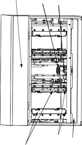
Component Identification
S Model Single Evaporator Models
|
EVAPORATOR |
REFRIGERATION |
|
ACCESS VALVES |
|
|
|
|
WATER |
ICE |
TOGGLE |
DISTRIBUTION |
THICKNESS |
SWITCH |
TUBE |
CONTROL |
|
WATER |
WATER CURTAIN |
CONTROL BOX |
TROUGH |
|
|
WATER INLET
LOCATION, THE
WATER INLET VALVE
IS LOCATED IN THE
REFRIGERATION
COMPARTMENT
WATER LEVEL |
WATER PUMP |
PROBE |
|
Part Number 80-1479-3 7/10 |
29 |
S Model Quad Evaporator Models
CONTROL BOX |
WATER PUMPS |
WATER LEVEL PROBE |
|
|
|
|
|
|
|
|
|
|
|
|
EVAPORATORS |
ICE DAMPERS |
WATER TROUGH |
30 |
Part Number 80-1479-3 7/10 |
Loading...