


 Loading...
Undercounter Ice Machines
Technician’s Handbook
This manual is updated as new information and models are released. Visit our website for the latest manual. www.kool-aire.com
Part Number STH047 5/16
Safety Notices
Read these precautions to prevent personal injury:
•Read this manual thoroughly before operating, installing or performing maintenance on the equipment. Failure to follow instructions in this manual can cause property damage, injury or death.
•Routine adjustments and maintenance procedures outlined in this manual are not covered by the warranty.
•Proper installation, care and maintenance are essential for maximum performance and trouble-free operation of your equipment.
•Visit our website www.kool-aire.com for manual updates, translations, or contact information for service agents in your area.
•This equipment contains high voltage electricity and refrigerant charge. Installation and repairs are to be performed by properly trained technicians aware of the dangers of dealing with high voltage electricity and refrigerant under pressure. The technician must also be certified in proper refrigerant handling
and servicing procedures. All lockout and tag out procedures must be followed when working on this equipment.
•This equipment is intended for indoor use only. Do not install or operate this equipment in outdoor areas.
•As you work on this equipment, be sure to pay close attention to the safety notices in this handbook. Disregarding the notices may lead to serious injury and/or damage to the equipment.

nWarning
Follow these electrical requirements during installation of this equipment.
•All field wiring must conform to all applicable codes of the authority having jurisdiction. It is the responsibility of the end user to provide the disconnect means to satisfy local codes. Refer to rating plate for proper voltage.
•This appliance must be grounded.
•This equipment must be positioned so that the plug is accessible unless other means for
disconnection from the power supply (e.g., circuit breaker or disconnect switch) is provided.
•Check all wiring connections, including factory terminals, before operation. Connections can become loose during shipment and installation.

nWarning
Follow these precautions to prevent personal injury during installation of this equipment:
•Installation must comply with all applicable equipment fire and health codes with the authority having jurisdiction.
•To avoid instability the installation area must be capable of supporting the combined weight of the equipment and product. Additionally the equipment must be level side to side and front to back.
•Ice machines require a deflector when installed on an ice storage bin. Prior to using a non-OEM ice storage system with this ice machine, contact the bin manufacturer to assure their ice deflector is compatible.
•Remove all removable panels before lifting and installing and use appropriate safety equipment during installation and servicing. Two or more people are required to lift or move this appliance to prevent tipping and/or injury.
•Do not damage the refrigeration circuit when installing, maintaining or servicing the unit.
•Connect to a potable water supply only.
•This equipment contains refrigerant charge.
•Installation of the line sets must be performed by a properly trained and EPA certified refrigeration technician aware of the dangers of dealing with refrigerant charged equipment.

nWarning
Follow these precautions to prevent personal injury while operating or maintaining this equipment.
•Legs or casters must be installed and the legs/ casters must be screwed in completely. When casters are installed the mass of this unit will allow it to move uncontrolled on an inclined surface. These units must be tethered/secured to comply with all applicable codes. Swivel casters must be mounted on the front and rigid casters must be mounted on the rear. Lock the front casters after installation is complete.
•Some 50 Hz models may contain up to 150 grams of R290 (propane) refrigerant. R290 (propane)
is flammable in concentrations of air between approximately 2.1% and 9.5% by volume (LEL lower explosion limit and UEL upper explosion limit). An ignition source at a temperature higher than 470°C is needed for a combustion to occur.
•Refer to nameplate to identify the type of refrigerant in your equipment.
•Only trained and qualified personnel aware of the dangers are allowed to work on the equipment.
•Read this manual thoroughly before operating, installing or performing maintenance on the equipment. Failure to follow instructions in this manual can cause property damage, injury or death.
•Crush/Pinch Hazard. Keep hands clear of moving components. Components can move without warning unless power is disconnected and all potential energy is removed.
•Moisture collecting on the floor will create a slippery surface. Clean up any water on the floor immediately to prevent a slip hazard.

nWarning
Follow these precautions to prevent personal injury while operating or maintaining this equipment.
•Objects placed or dropped in the bin can affect human health and safety. Locate and remove any objects immediately.
•Never use sharp objects or tools to remove ice or frost.
•Do not use mechanical devices or other means to accelerate the defrosting process.
•When using cleaning fluids or chemicals, rubber gloves and eye protection (and/or face shield) must be worn.
 DANGER
Do not operate equipment that has been misused, abused, neglected, damaged, or altered/modified from that of original manufactured specifications. This appliance is not intended for use by persons (including children) with reduced physical, sensory or mental capabilities, or lack of experience and knowledge, unless they have been given supervision concerning use of the appliance by a person responsible for their safety. Do not allow children to play with, clean or maintain this appliance without proper supervision.

 DANGER
Follow these precautions to prevent personal injury during use and maintenance of this equipment:
•It is the responsibility of the equipment owner to perform a Personal Protective Equipment Hazard Assessment to ensure adequate protection during maintenance procedures.
•Do Not Store Or Use Gasoline Or Other Flammable Vapors Or Liquids In The Vicinity Of This Or Any Other
•Appliance. Never use flammable oil soaked cloths or combustible cleaning solutions for cleaning.
•All covers and access panels must be in place and properly secured when operating this equipment.
•Risk of fire/shock. All minimum clearances must be maintained. Do not obstruct vents or openings.
•Failure to disconnect power at the main power supply disconnect could result in serious injury or death. The power switch DOES NOT disconnect all incoming power.
•All utility connections and fixtures must be maintained in accordance with the authority having jurisdiction.
•Turn off and lockout all utilities (gas, electric, water) according to approved practices during maintenance or servicing.
•Units with two power cords must be plugged into individual branch circuits. During movement, cleaning or repair it is necessary to unplug both power cords.
We reserve the right to make product improvements at any time. Specifications and design are subject to change without notice.

Table of Contents
General Information
Model Numbers . . . . . . . . . . . . . . . . . . . . . . . . . . . . . . . 13
How to Read a Model Number . . . . . . . . . . . . . . .14.
Accessories . . . . . . . . . . . . . . . . . . . . . . . . .14. . . . .
Bin Caster . . . . . . . . . . . . . . . . . . . . . . . . . . . . . . . . . 14
Cleaner and Sanitizer . . . . . . . . . . . . . . . . . . . . . . 14
Model/Serial Number Location . . . . . . . . . . . . . 15. .
Ice Machine Warranty Information . . . . . . . . . . . . 15
Installation |
|
Location of Ice Machine . . . . . . . . . . . . . . . . . . . . . . . |
17 |
Ice Machine Clearance Requirements . . . . . . . . . |
18 |
Ice Machine Heat of Rejection . . . . . . . . . . . . |
18. . . . |
Leveling the Ice Machine . . . . . . . . . . . . . . . . . . . . . . |
19 |
Electrical Requirements. . . . . . . . . . . . . . . . . . . . . . . |
20 |
Voltage . . . . . . . . . . . . . . . . . . . . . . . . . . . . |
20. . . . . . |
Fuse/Circuit Breaker . . . . . . . . . . . . . . . . . . . . . . |
20. |
Total Circuit Ampacity . . . . . . . . . . . . . . . . . . . . |
20. |
Electrical Specifications . . . . . . . . . . . . . . . . . . . . . . . |
21 |
Air-cooled Ice Machine . . . . . . . . . . . . . . . . . . |
21. . |
Water-cooled Ice Machines . . . . . . . . . . . . . . |
22. . |
Water Service/Drains . . . . . . . . . . . . . . . . . . |
23. . . . . |
Water Supply . . . . . . . . . . . . . . . . . . . . . . . . . . . . . . |
23 |
Water Inlet Lines . . . . . . . . . . . . . . . . . . . |
23. . . . . |
Drain Connections . . . . . . . . . . . . . . . . . |
23. . . . . |
Water Supply and Drain Line Sizing/ |
|
Connections . . . . . . . . . . . . . . . . . . . . . . . . . . . . . . |
24 |
Cooling Tower Applications . . . . . . . . . . . . . . . . |
25 |
Component Identification |
|
Evaporator Compartment . . . . . . . . . . . . . . |
27. . . . . |
Part Number STH047 5/16 |
9 |
Maintenance
Ice Machine Inspection . . . . . . . . . . . . . . . . . . . . 29 Exterior Cleaning . . . . . . . . . . . . . . . . . . . . . . . . . . 29 Cleaning the Condenser . . . . . . . . . . . . . . . . . . . 29 Interior Cleaning and Sanitizing . . . . . . . . . . . . 31
Removal from Service/Winterization . . . . . . . 44. .
Operation
Initial Start-up or Start-up After Automatic Shut-off . . . . . . . . . . . . . . . . . . . . . . . . . . . . . . . . . . . 47 Freeze Sequence . . . . . . . . . . . . . . . . . . . . . . . . 47. . Harvest Sequence . . . . . . . . . . . . . . . . . . . . . . . . . 48 Automatic Shut-off . . . . . . . . . . . . . . . . . . . . . . . . 48 Energized Parts Chart . . . . . . . . . . . . . . . . . . . . . . 49
Operational Checks . . . . . . . . . . . . . . . . . . . . . . . . . . . 51
Troubleshooting
Diagnosing an Ice Machine that Will Not Run . ..
. . . . . . . . . . . . . . . . . . . . . . . . . . . . . . . . . . . . . . . . . . . 54 Diagnosing Ice Thickness Control Circuitry . 55 Ice Production Check . . . . . . . . . . . . . . . . . . . . . . 58 Installation and Visual Inspection Checklist . 60 Water System Checklist . . . . . . . . . . . . . . . . . . . . 61 Ice Formation Pattern. . . . . . . . . . . . . . . . . . . . . . 62 Safety Limit Feature . . . . . . . . . . . . . . . . . . . 64. . . .
Analyzing Discharge Pressure . . . . . . . . . . . 71. . Analyzing Suction Pressure . . . . . . . . . . . . . . . . 73 Harvest Valve . . . . . . . . . . . . . . . . . . . . . . . . . . . . . . 77 Comparing Evaporator Inlet/Outlet Temperatures . . . . . . . . . . . . . . . . . . . . . . . . .81. . . .
Discharge Line Temperature Analysis . . . . . . . 82 Refrigeration Component Diagnostic Chart 84 Procedure . . . . . . . . . . . . . . . . . . . . . . . . . . . . . . . . . 85 Final Analysis . . . . . . . . . . . . . . . . . . . . . . . . . . . . . . 86 Refrigeration Component Diagnostic Chart 87 Ice Quality Is Poor — Cubes are Shallow, Incomplete or White . . . . . . . . . . . . . . . . . . . . . . . 90 Freeze Cycle Is Long, Low Ice Production . . . 91 Ice Machine Runs and No Ice Is Produced. . . 92
10 |
Part Number STH047 5/16 |
Component Check Procedures |
|
Main Fuse . . . . . . . . . . . . . . . . . . . . . . . . . . . . . . . . . . . . |
. 93 |
Bin Switch . . . . . . . . . . . . . . . . . . . . . . . . . . . . . . . . . . . . |
. 94 |
Diagnosing Start Components . . . . . . . . . . . . . . . |
. 97 |
Capacitor . . . . . . . . . . . . . . . . . . . . . . . . |
. 97. . . . . |
Relay . . . . . . . . . . . . . . . . . . . . . . . . . . . . . . . . . . . . . |
. 97 |
ON/OFF/WASH Toggle Switch . . . . . . . . . . . . . . . . |
. 98 |
Ice Thickness Probe .. .. .. .. .. .. .. .. .. .. .. .. .. .. .. .. .. .. .. .. .. .. .. .. .. .. |
.. 99 |
Ice Thickness Check . . . . . . . . . . . . . . . . |
.100. . . . . |
Compressor Electrical Diagnostics . . . . . . . . . . . |
101 |
Fan Cycle Control . . . . . . . . . . . . . . . . . . . . |
.103. . . . . . |
High Pressure Cutout (HPCO) Control . . . . . . . . |
104 |
Filter-Driers . . . . . . . . . . . . . . . . . . . . . . . . . . . . . . . . . . |
105 |
Refrigerant Recovery/Evacuation . . . . . . . . . . . . |
106 |
Refrigerant Re-use Policy . . . . . . . . . . . . . . . |
107. . |
Recovery and Recharging Procedures . . |
.109. |
System Contamination Cleanup . . . . . . . . . . |
112. . . |
Mild System Contamination Cleanup |
|
Procedure . . . . . . . . . . . . . . . . . . . . . . . . . . . . . . . . |
114 |
Severe System Contamination Cleanup |
|
Procedure . . . . . . . . . . . . . . . . . . . . . . . . . . . . . . . . |
115 |
Replacing Pressure Controls without |
|
Removing Refrigerant Charge. . . . . . . . . . . . . |
117 |
K270 Condenser Fan Motor Access. . . . . . . . . . . |
119 |
Part Number STH047 5/16 |
11 |
Component Specifications
Main Fuse . . . . . . . . . . . . . . . . . . . . . . . . . . . . . . . . . . . . 121
Bin Switch . . . . . . . . . . . . . . . . . . . . . . . . . . . . . . . . . . . . 121
ON/OFF/WASH Toggle Switch . . . . . . . . . . . . . . . . 121
Fan Control Cycle . . . . . . . . . . . . . . . . . . . . .121. . . . . . .
High Pressure Cutout (HPCO) Control . . . . . . . . 121
Filter-Driers . . . . . . . . . . . . . . . . . . . . . . . . . . . . . . . . . . 121
Total System Refrigerant Charge. . . . . . . . . . . . . 122
Charts
Cycle Times, 24 Hr. Ice Production and
Refrigerant Pressure Charts. . . . . . . . . . . . . . . . . . 123
K170 Self-contained Air-cooled . . . . . . . . . . .124
K270 Self-contained Air-cooled . . . . . . . . . . .125
K270 Self-contained Water-cooled . . . . . . . 126.
Diagrams
Wiring Diagrams . . . . . . . . . . . . . . . . . . . . . . . . . . . . . 127
K170 / K270 Wiring Diagram . . . . . . . . . . . . . 128.
Electronic Control Boards . . . . . . . . . . . . . . . . . . . . 130
K170/K270 Tubing Schematic . . . . . . . . . . . . . 131
12 |
Part Number STH047 5/16 |

General Information
Model Numbers
This manual covers the following models:
Self-contained Air-cooled |
Self-contained Water-cooled |
KD0172A |
N/A |
KY0174A |
N/A |
KR0270A |
KR0271W |
KD0272A |
KD0273W |
KY0274A |
KY0275W |
nWarning
An ice machine contains high voltage electricity and refrigerant charge. Repairs are to be performed by properly trained refrigeration technicians aware of the dangers of dealing with high voltage electricity and refrigerant under pressure.
Part Number STH047 5/16 |
13 |
How to Read a Model Number
|
|
|
|
|
|
|
|
|
|
|
|
|
|
|
|
|
|
|
|
|
|
|
|
|
|
|
|
Cube Size |
|
|
|
|
|
|
|
|
Capacity |
|
|
|
|||||||||
|
|
|
|
|
|
|
|
|
|
|
|
|
|
|
||||||||||
|
|
|
|
|
|
|
|
|
|
|
|
|
|
|
|
|
|
|
|
|
|
|||
|
|
|
|
|
|
|
|
|
|
|
|
|
|
|
|
|
|
|
|
Condenser |
|
|||
|
|
Series |
|
|
|
|
|
|
|
|
|
|
|
|
|
|
|
|
||||||
|
|
|
|
|
|
|
|
|
|
|
|
|
|
|
|
|
|
Type |
|
|
||||
|
|
|
|
|
|
|
|
|
|
|
|
|
|
|
|
|
|
|
|
|
||||
|
|
|
|
|
|
|
|
|
|
|
|
|
|
|
|
|
|
|
|
|
||||
|
|
|
|
|
K |
|
D |
|
0172 |
|
A |
|
|
|
||||||||||
|
|
|
|
|
|
|
|
|
||||||||||||||||
|
|
|
|
|
|
|
|
|
|
|
|
|
|
|
|
|
|
|
|
|
|
|
|
|
|
|
|
|
|
|
|
|
|
|
|
|
|
|
|
|
|
|
|
|
|
|
|
|
|
|
|
|
|
|
|
|
|
|
|
|
|
|
|
|
|
|
|
|
|
A - Air-cooled |
|
|||
|
|
|
|
|
|
|
|
|
|
|
|
|
|
|
|
|
|
|
|
|
||||
|
|
|
|
|
|
|
|
|
|
|
|
|
|
|
|
|
|
|
|
|
|
|
||
|
|
D - Dice |
|
|
|
|
|
|
|
|
|
|
|
|
|
|
|
|
|
|
||||
|
|
Y - Half-dice |
|
|
|
2 - Dice, Air-cooled |
|
|
|
|||||||||||||||
|
|
|
|
|
|
|
|
|
|
|
|
|
||||||||||||
|
|
|
|
|
|
|
|
|
|
4 - Half-dice, Air-cooled |
|
|||||||||||||
|
|
|
|
|
|
|
|
|
|
|
|
|
|
|
|
|
|
|
|
|
|
|
|
|
Accessories
Contact your distributor for these optional accessories:
BIN CASTER
Replaces standard legs.
CLEANER AND SANITIZER
Manitowoc Ice Machine Cleaner and Sanitizer are available in convenient 16 oz. (473 ml) and 1 gal (3.78 l) bottles. These are the only cleaner and sanitizer approved for use with Koolaire products.
Cleaner Part Number |
Sanitizer Part Number |
||
16 oz |
94-0456-3 |
16 oz |
94-0565-3 |
*16 oz 000000084 |
|
|
|
1 Gallon |
4-0580-3 |
1 Gallon |
94-0581-3 |
14 |
Part Number STH047 5/16 |
Model/Serial Number Location
The model and serial numbers are required when requesting information from your local distributor, service representative, or Manitowoc KitchenCare®. The model and serial number are listed on the OWNER WARRANTY REGISTRATION CARD. They are also listed on the MODEL/ SERIAL NUMBER DECAL affixed to the ice machine.
MODEL/SERIAL |
MODEL/SERIAL |
NUMBER PLATE |
NUMBER PLATE |
SV1687G
Model/Serial Number Location
Ice Machine Warranty Information
For warranty information visit: http://www.koo-aire.com/Service/Warranty
•Warranty Verification
•Warranty Registration
•View and download a copy of the warranty
Part Number STH047 5/16 |
15 |
THIS PAGE INTENTIONALLY LEFT BLANK
16 |
Part Number STH047 5/16 |

Installation
Location of Ice Machine
The location selected for the ice machine must meet the following criteria. If any of these criteria are not met, select another location.
•The location must be indoors.
•The location must be free of airborne and other contaminants.
•Air temperature:
•Must be at least 40°F (4°C) but must not exceed 110°F (43.4°C).
•The location must not be near heat-generating equipment or in direct sunlight.
•The location must be capable of supporting the weight of the ice machine and a full bin of ice.
•The location must allow enough clearance for water, drain, and electrical connections in the rear of the ice machine.
•The location must not obstruct airflow through or around the ice machine (condenser airflow is in and out the front). Refer to the chart below for clearance requirements.
•The ice machine must be protected if it will be subjected to temperatures below 32°F (0°C). Failure caused by exposure to freezing temperatures is not covered by the warranty.
Part Number STH047 5/16 |
17 |
Ice Machine Clearance Requirements
|
Self-contained |
|
Air-cooled |
Top/Sides |
5" (127 mm)* |
Back |
5" (127 mm)* |
*NOTE: The ice machine may be built into a cabinet.
There is no minimum clearance requirement for the top or left and right sides of the ice machine. The listed values are recommended for efficient operation and servicing only.
Ice Machine Heat of Rejection
Series |
Heat of Rejection* |
|
|
Ice Machine |
Air Conditioning** |
|
Peak |
K170 |
2200 |
|
2600 |
K270 |
3800 |
|
6000 |
*B.T.U./Hour
**Because the heat of rejection varies during the ice making cycle, the figure shown is an average.
Ice machines, like other refrigeration equipment, reject heat through the condenser. It is helpful to know the amount of heat rejected by the ice machine when sizing air conditioning equipment where self-contained aircooled ice machines are installed.
18 |
Part Number STH047 5/16 |
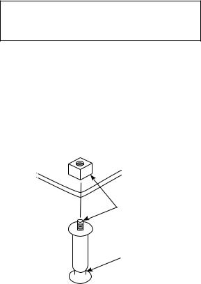
Leveling the Ice Machine
1.Screw the leveling legs onto the bottom of the ice machine.
2.Screw the foot of each leg in as far as possible.
,Caution
The legs must be screwed in tightly to prevent them from bending.
3.Move the ice machine into its final position.
4.Level the ice machine to ensure that the siphon system functions correctly. Use a level on top of the ice machine. Turn each foot as necessary to level the ice machine from front to back and side to side.
NOTE: An optional 2-1/2" (6.35 cm) caster assembly is available for use in place of the legs on the K170, K210, and K270. Installation instructions are supplied with the casters.
THREAD
LEVELING LEG
INTO BASE OF
CABINET
THREAD “FOOT”
IN AS FAR AS
POSSIBLE
SV1606
Leg Installation
Part Number STH047 5/16 |
19 |
Electrical Requirements
VOLTAGE
The maximum allowable voltage variation is ±10% of the rated voltage on the ice machine model/serial number plate at start-up (when the electrical load is highest).
The 115/1/60 ice machines are factory pre-wired with a 6' (1.8 m) power cord, and NEMA 5-15P-plug configuration.
The 208-230/1/60 and 230/1/50 ice machines are factory pre-wired with a power cord only, no plug is supplied.
FUSE/CIRCUIT BREAKER
A separate fuse/circuit breaker must be provided for each ice machine. Circuit breakers must be H.A.C.R. rated (does not apply in Canada).
TOTAL CIRCUIT AMPACITY
The total circuit ampacity is used to help select the wire size of the electrical supply.
The wire size (or gauge) is also dependent upon location, materials used, length of run, etc., so it must be determined by a qualified electrician.
20 |
Part Number STH047 5/16 |
Electrical Specifications
AIR-COOLED ICE MACHINE
Ice Machine |
Voltage Phase |
Max. Fuse/ |
Total |
|
Cycle |
Circuit |
Amps |
|
|
Breaker |
|
K170 |
115/1/60 |
15 amp |
7.0 |
|
208/1/60 |
15 amp |
3.5 |
|
230/1/50 |
15 amp |
4.0 |
K270 |
115/1/60 |
15 amp |
10.7 |
|
208-230/1/60 |
15 amp |
5.2 |
|
230/1/50 |
15 amp |
5.2 |
nWarning
All wiring must conform to local, state and national codes.
nWarning
The ice machine must be grounded in accordance with national and local electrical code.
Part Number STH047 5/16 |
21 |
WATER-COOLED ICE MACHINES
Ice Machine |
Voltage |
Max. Fuse/ |
Total |
|
Phase Cycle |
Circuit |
Amps |
|
|
Breaker |
|
K170 |
115/1/60 |
15 amp |
6.3 |
|
208/1/60 |
15 amp |
3.6 |
|
230/1/50 |
15 amp |
4.0 |
K270 |
115/1/60 |
15 amp |
9.9 |
|
208-230/1/60 |
15 amp |
4.7 |
|
230/1/50 |
15 amp |
4.7 |
22 |
Part Number STH047 5/16 |

Water Service/Drains
WATER SUPPLY
Local water conditions may require treatment of the water to inhibit scale formation, filter sediment, and remove chlorine odor and taste.
Importan
If you are installing a water filter system, refer to the Installation Instructions supplied with the filter system for ice making water inlet connections.
WATER INLET LINES
Follow these guidelines to install water inlet lines:
•Do not connect the ice machine to a hot water supply. Be sure all hot water restrictors installed for other equipment are working. (Check valves on sink faucets, dishwashers, etc.)
•If water pressure exceeds the maximum recommended pressure, 80 psig (5.5 bar) obtain a water pressure regulator from your distributor.
•Install a water shut-off valve for ice making potable water.
•Insulate water inlet lines to prevent condensation.
DRAIN CONNECTIONS
Follow these guidelines when installing drain lines to prevent drain water from flowing back into the ice machine and storage bin:
•Drain lines must have a 1.5-inch drop per 5 feet of run (2.5 cm per meter), and must not create traps.
•The floor drain must be large enough to accommodate drainage from all drains.
•Run separate bin and ice machine drain lines. Insulate them to prevent condensation.
•Vent the bin and ice machine drain to the atmosphere.
Part Number STH047 5/16 |
23 |
24 |
|
|
|
|
|
|
|
|
|
|
|
|
|
Water |
Water |
Ice Machine |
Tubing Size Up |
|
Location |
to Ice Machine |
|||
|
Temperature |
Pressure |
Fitting |
||
|
|
Fitting |
|||
|
|
|
|
|
|
|
|
|
|
|
|
|
Ice Making |
40°F (4°C) min. 90°F |
20 psi (1.38 bar) min. |
3/8” Female |
3/8" (9.5 mm) min. |
|
Water Inlet |
(32.2°C) max. |
80 psi (5.5 bar) max. |
Pipe Thread |
inside diameter |
|
|
|
|
|
|
|
Condenser |
33°F (0.6°C) min. |
20 psi (1.38 bar) min. |
3/8” Female |
3/8" (9.5 mm) min. |
|
Water Inlet |
90°F (32.2°C) max. |
150 psi (10.3 bar) max. |
Pipe Thread |
inside diameter |
|
|
|
|
|
|
|
Condenser |
— |
— |
3/8” Female |
3/8" (9.5 mm) min. |
|
Water Drain |
Pipe Thread |
inside diameter |
||
|
|
|
|||
|
|
|
|
|
|
|
|
|
|
1/2” Female |
1/2" (12.7 mm) |
|
Bin Drain |
— |
— |
min. inside |
|
|
Pipe Thread |
||||
|
|
|
|
diameter |
|
5/16 STH047 Number Part |
|
|
|
|
|
|
|
|
|
|
|
|
|
|
|
|
SIZING/ LINE DRAIN AND SUPPLY WATER CONNECTIONS
COOLING TOWER APPLICATIONS Water Cooled Models Only
A water-cooling tower installation does not require modification of the ice machine. The water regulator valve for the condenser continues to control the refrigeration discharge pressure.
It is necessary to know the amount of heat rejected, and the pressure drop through the condenser and water valves (inlet to outlet) when using a cooling tower on an ice machine.
•Water entering the condenser must not exceed 90°F (32.2°C).
•Water flow through the condenser must not exceed 5 gallons (19 liters) per minute.
•Allow for a pressure drop of 7 psig (.48 bar) between the condenser water inlet and the outlet of the ice machine.
•Water exiting the condenser must not exceed 110°F (43.3°C).
,Caution
Plumbing must conform to state and local codes.
Part Number STH047 5/16 |
25 |
THIS PAGE INTENTIONALLY LEFT BLANK
26 |
Part Number STH047 5/16 |

Component Identification
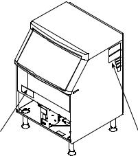
Evaporator Compartment
ICE THICKNESS
PROBE
DISTRIBUTION TUBE
|
ICE |
|
DAMPER WATER |
WATER |
PUMP |
|
|
TROUGH |
|
SV1694A
FLOAT VALVE
SIPHON CAP
BIN SWITCH
MAGNET
SV1695A
Evaporator Compartment
Part Number STH047 5/16 |
27 |
ON/OFF/WASH
TOGGLE
SWITCH
CONDENSED AIR |
COMPRESSOR |
|
COMPARTMENT |
||
FILTER |
||
ACCESS SCREWS |
||
|
||
|
SV1686G |
K170 Ice Machines
ON/OFF/WASH
TOGGLE
SWITCH
CONDENSED AIR


 FILTER COMPRESSOR


COMPARTMENT ACCESS
SCREWS
PT1288
K270 Ice Machines
28 |
Part Number STH047 5/16 |
Maintenance
ICE MACHINE INSPECTION
Check all water fittings and lines for leaks. Also, make sure the refrigeration tubing is not rubbing or vibrating against other tubing, panels, etc.
Do not put anything (boxes, etc.) in front of the ice machine. There must be adequate airflow through and around the ice machine to maximize ice production and ensure long component life.
EXTERIOR CLEANING
Clean the area around the ice machine as often as necessary to maintain cleanliness and efficient operation.
Sponge any dust and dirt off the outside of the ice machine with mild soap and water. Wipe dry with a clean, soft cloth.
A commercial grade stainless steel cleaner/polish can be used as necessary.
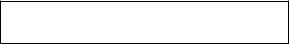
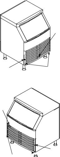
CLEANING THE CONDENSER
nWarning
Disconnect electric power to the ice machine at the electric service switch before cleaning the condenser.
,Caution
If you are cleaning the condenser fan blades with water, cover the fan motor to prevent water damage.
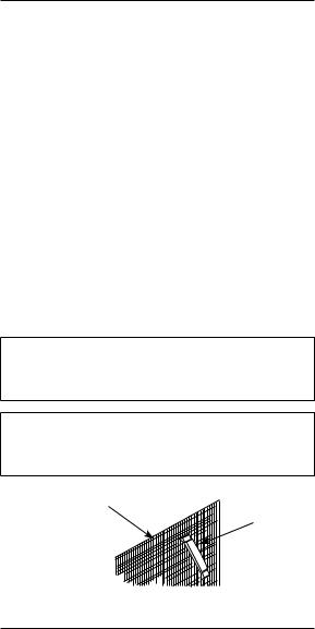
|
CONDENSER |
COMB |
FIN COMB |
DOWN |
|
ONLY |
|
Part Number STH047 5/16 |
29 |

Air-cooled Condenser
A dirty condenser restricts airflow, resulting in excessively high operating temperatures. This reduces ice production and shortens component life. Clean the condenser at least every six months. Follow the steps below.
nWarning
The condenser fins are sharp. Use care when cleaning them.
1.The washable aluminum filter on self-contained aircooled ice machines is designed to catch dust, dirt, lint and grease. This helps keep the condenser clean. Clean the filter with a mild soap and water solution.
2.Clean the outside of the condenser with a soft brush or a vacuum with a brush attachment. Clean from top to bottom, not side to side. Be careful not to bend the condenser fins.
3.Shine a flashlight through the condenser to check for dirt between the fins. If dirt remains:
A.Blow compressed air through the condenser fins from the inside. Be careful not to bend the fan blades.
B.Use a commercial condenser coil cleaner. Follow the directions and cautions supplied with the cleaner.
4.Straighten any bent condenser fins with a fin comb.
5.Carefully wipe off the fan blades and motor with a soft cloth. Do not bend the fan blades. If the fan
blades are excessively dirty, wash with warm, soapy water and rinse thoroughly.
30 |
Part Number STH047 5/16 |
Loading...