


 Manitowoc

UG Models
Technician’s Handbook
This manual is updated as new information and models are released. Visit our website for the latest manual. www.manitowocice.com
America’s #1 Selling Ice Machine
Manitowoc Ice P/N 040004390 11/14
Safety Notices
When using or servicing these Ice Machines, be sure to pay close attention to the safety notices in this handbook. Disregarding the notices may lead to serious injury and/or damage to the ice machine.
Throughout this handbook, you will see the following types of safety notices:
! Warning
Text in a Warning box alerts you to a potential personal injury situation. Be sure to read the Warning statement before proceeding, and work carefully.
! Caution
Text in a Caution box alerts you to a situation in which you could damage the ice machine. Be sure to read the Caution statement before proceeding, and work carefully.

Procedural Notices
When using or servicing these Ice Machines, be sure to read the procedural notices in this handbook. These notices supply helpful information that may assist you as you work.
Throughout this handbook, you will see the following types of procedural notices:
Important
Text in an Important box provides you with information that may help you perform a procedure more efficiently. Disregarding this information will not cause damage or injury, but may slow you down as you work.
NOTE: Text set off as a Note provides you with simple, but useful extra information about the procedure you are performing.
Read These Before Proceeding:
! Caution
Proper installation, care and maintenance are essential for maximum ice production and trouble free operation of your Manitowoc Ice Machine. If you encounter problems not covered by this manual, do not proceed, contact Manitowoc Ice, Inc. We will be happy to provide assistance.
Important
Routine adjustments and maintenance procedures outlined in this manual are not covered by the warranty.
We reserve the right to make product improvements at any time. Specifications and design are subject to change without notice.
! Warning
PERSONAL INJURY POTENTIAL
Do not operate equipment that has been misused, abused, neglected, damaged, or altered/modified from that of original manufactured specifications.
! Warning
POTENTIAL PERSONAL INJURY SITUATION
This ice machine contains refrigerant charge. Installation and Servicing must be performed by a properly trained refrigeration technician aware of the
Dangers of dealing with refrigerant charged equipment.
This Page Intentionally Left Blank
Table of Contents
Table of Contents . . . . . . . . . . . . . . . . . . . . . . . . . . 1
General Information 1
Model Numbers . . . . . . . . . . . . . . . . . . . . . . . . . . . . 1
Installation 3
Location of Ice Machine . . . . . . . . . . . . . . . . . . . . . 3
Water Service/Drains . . . . . . . . . . . . . . . . . . . . . . 4 Electrical Requirements . . . . . . . . . . . . . . . . . . . . 5 Electrical Specifications . . . . . . . . . . . . . . . . . . . . 6 Power Consumption - kwh per 24 hours . . . . . . . 7 Ice Machine Heat of Rejection . . . . . . . . . . . . . . . 8
Component Identification 9
Component Removal . . . . . . . . . . . . . . . . . . . . . 11 Spray Bar . . . . . . . . . . . . . . . . . . . . . . . . . . . . . . 15
Maintenance 17
Cleaning & Sanitizing Procedure . . . . . . . . . . . . 18
Operation 23
Sequence Of Operation . . . . . . . . . . . . . . . . . . . . 23
Cube Shape . . . . . . . . . . . . . . . . . . . . . . . . . . . . 27
Troubleshooting 29
All Models . . . . . . . . . . . . . . . . . . . . . . . . . . . . . . . 29
Ice Machine Will Not Run. . . . . . . . . . . . . . . . . . 29 Compressor Won’t Run . . . . . . . . . . . . . . . . . . . 30 Compressor Electrical Diagnostics. . . . . . . . . . . 31 Diagnosing Start Components . . . . . . . . . . . . . . 33 Water Pump Won’t Run . . . . . . . . . . . . . . . . . . . 34 Hot Gas Valve Won’t Energize. . . . . . . . . . . . . . 34 Water Inlet Valve Won’t Energize. . . . . . . . . . . . 34 Ice Machine Prematurely Harvests . . . . . . . . . . 35 ce Machine Will Not Harvest . . . . . . . . . . . . . . . 36 Evaporator Thermostat. . . . . . . . . . . . . . . . . . . . 37
Water System Checklist . . . . . . . . . . . . . . . . . . . . 44 Ice Production Check . . . . . . . . . . . . . . . . . . . . . . 45 Analyzing Discharge Pressure . . . . . . . . . . . . . . 46
Discharge Pressure High Checklist . . . . . . . . . . 47 Freeze Cycle Discharge Pressure Low Checklist 48
Analyzing Suction Pressure. . . . . . . . . . . . . . . . . 49
Suction Pressure High Checklist . . . . . . . . . . . . 51
Suction Pressure Low Checklist . . . . . . . . . . . . . 52
Discharge Line Temperature Analysis. . . . . . . . . 53
Component Check Procedures 55
On/Off/Wash-Fill Toggle Switch . . . . . . . . . . . . . 55 Bin thermistor (T3). . . . . . . . . . . . . . . . . . . . . . . . 56 SUMP WATER THERMiSTOR (T1)& LIQUID LINE THERMiSToR(T2). . . . . . . . . . . . . . . . . . . . . . . 58 high Pressure Cutout (HPCO) Control . . . . . . . . 65 Hot Gas Valve . . . . . . . . . . . . . . . . . . . . . . . . . . . 66
Refrigerant . . . . . . . . . . . . . . . . . . . . . . . . . . . . . . . 71
Recover/Evacuation/Charging. . . . . . . . . . . . . . . 71 System Contamination Cleanup . . . . . . . . . . . . . 74 Mild System Contamination Cleanup . . . . . . . . . 76 Severe System Contamination Cleanup Procedure
77
Filter-Driers . . . . . . . . . . . . . . . . . . . . . . . . . . . . . 79 Total System Refrigeration Charge . . . . . . . . . . 80
Cycle Times/24 Hour Ice Production and Refrigerant Pressure Charts 81
ug18A Self-Contained Air-Cooled — Standard Cube . . . . . . . . . . . . . . . . . . . . . . . . . . . . . . . . . 82
ug18A Self-Contained Air-Cooled — Standard Cube (Continued) . . . . . . . . . . . . . . . . . . . . . . . 83
ug18A Self-Contained Air-Cooled — Standard Cube (Continued) . . . . . . . . . . . . . . . . . . . . . . . 84
UG020A Self-Contained Air-Cooled — Standard Cube . . . . . . . . . . . . . . . . . . . . . . . . . . . . . . . . . 85
UG020A Self-Contained Air-Cooled — Standard Cube (Continued) . . . . . . . . . . . . . . . . . . . . . . . 86
UG020A Self-Contained Air-Cooled — Standard Cube (Continued) . . . . . . . . . . . . . . . . . . . . . . . 87
UG030A-251 Self-Contained Air-Cooled — Standard Cube . . . . . . . . . . . . . . . . . . . . . . . . . . . . . 88
UG030A-251 Self-Contained Air-Cooled — Standard Cube . . . . . . . . . . . . . . . . . . . . . . . . . . . . . 89
UG030A-251 Self-Contained Air-Cooled — Standard Cube (Continued) . . . . . . . . . . . . . . . . . . . 90
UG030A-261 Self-Contained Air-Cooled — Standard Cube . . . . . . . . . . . . . . . . . . . . . . . . . . . . . 91
UG030A-261 Self-Contained Air-Cooled — Standard Cube . . . . . . . . . . . . . . . . . . . . . . . . . . . . . 92
UG030A-261 Self-Contained Air-Cooled — Stan-
dard Cube (Continued) . . . . . . . . . . . . . . . . . . 93 UG030A-161 Self-Contained Air-Cooled — Stan-
dard Cube . . . . . . . . . . . . . . . . . . . . . . . . . . . . 94 UG030A-161 Self-Contained Air-Cooled — Stan-
dard Cube . . . . . . . . . . . . . . . . . . . . . . . . . . . . 95 UG030A-161 Self-Contained Air-Cooled — Stan-
dard Cube (Continued) . . . . . . . . . . . . . . . . . . 96 UG030W Self-Contained WATER--Cooled —
Standard Cube. . . . . . . . . . . . . . . . . . . . . . . . . 97 UG030W Self-Contained WATER--Cooled —
Standard Cube. . . . . . . . . . . . . . . . . . . . . . . . . 98 UG030W Self-Contained WATER--Cooled —
Standard Cube (Continued). . . . . . . . . . . . . . . 99 UG040A-251 Self-Contained Air-Cooled — Standard Cube . . . . . . . . . . . . . . . . . . . . . . . . . . . 100 UG040A-251 Self-Contained Air-Cooled — Standard Cube (Continued) . . . . . . . . . . . . . . . . . 101 UG040A-251 Self-Contained Air-Cooled — Standard Cube (Continued) . . . . . . . . . . . . . . . . . 102 UG040A-261 Self-Contained Air-Cooled — Stan-
dard Cube . . . . . . . . . . . . . . . . . . . . . . . . . . . 103 UG040A-261 Self-Contained Air-Cooled — Stan-
dard Cube (Continued) . . . . . . . . . . . . . . . . . 104 UG040A-261 Self-Contained Air-Cooled — Stan-
dard Cube (Continued) . . . . . . . . . . . . . . . . . 105 UG050A-251 Self-Contained Air-Cooled — Stan-
dard Cube . . . . . . . . . . . . . . . . . . . . . . . . . . . 106 UG050A-251 Self-Contained Air-Cooled — Stan-
dard Cube (Continued) . . . . . . . . . . . . . . . . . 107 UG050A-251 Self-Contained Air-Cooled — Stan-
dard Cube (Continued) . . . . . . . . . . . . . . . . . 108 UG050W Self-Contained water-Cooled . . . . . . 109 UG050W Self-Contained water-Cooled . . . . . . 110 UG050W Self-Contained water-Cooled . . . . . . 111 UG065AG-251G Self-Contained Air-Cooled —
Standard Cube. . . . . . . . . . . . . . . . . . . . . . . . 112 UG065 Self-Contained Air-Cooled — Standard
Cube (Continued) . . . . . . . . . . . . . . . . . . . . . 113 UG065 Self-Contained Air-Cooled — Standard
Cube (Continued) . . . . . . . . . . . . . . . . . . . . . 114 UG080A Self-Contained Air-Cooled — Standard
Cube . . . . . . . . . . . . . . . . . . . . . . . . . . . . . . . 115 UG080A Self-Contained Air-Cooled — Standard
Cube (Continued) . . . . . . . . . . . . . . . . . . . . . 116 UG080A Self-Contained Air-Cooled — Standard
Cube (Continued) . . . . . . . . . . . . . . . . . . . . . . 117
Diagrams 119
Wiring Diagram. . . . . . . . . . . . . . . . . . . . . . . . . . . 119
UG18/UG20 air-cooled . . . . . . . . . . . . . . . . . . . 119
UG30/UG50/UG65 air-cooled . . . . . . . . . . . . . . 120
UG30/UG50 water-cooled . . . . . . . . . . . . . . . . 122
Tubing Schematics . . . . . . . . . . . . . . . . . . . . . . . 123
ug18/UG20/UG30/UG40/UG65 Tubing Schematic .
123
UG50/UG80 Tubing Schematic. . . . . . . . . . . . . 124
General Information
Model Numbers
This manual covers the following models:
Self-Contained |
Water-Cooled |
|
Air-Cooled |
||
|
||
UG018A |
N/A |
|
UG020A |
N/A |
|
UG030A |
UG030W |
|
UG040A |
N/A |
|
UG050A |
UG050W |
|
UG065A |
N/A |
|
UG080A |
N/A |
–1–
This Page Intentionally Left Blank
–2–

Installation
Location of Ice Machine
The location selected for the ice machine must meet the following criteria. If any of these criteria are not met, select another location.
•The location must be indoors.
•The location must be free of airborne and other contaminants.
•The air temperature must be at least 10ºC but must not exceed 43.4ºC.
•The location must not be near heat-generating equipment or in direct sunlight.
•The location must be capable of supporting the weight of the ice machine and a full bin of ice.
•The location must allow enough clearance for water, drain, and electrical connections in the rear of the ice machine.
•The location must not obstruct airflow through or around the ice machine (condenser airflow is in and out the front). Refer to the chart below f or clearance requirements.
|
Self-Contained |
Self-Contained |
|
Air-Cooled |
Water-Cooled |
|
|
|
Top/Sides |
203 mm (8")* |
127 mm (5")* |
|
|
|
Back |
127 mm (5")* |
127 mm (5")* |
*NOTE: The ice machine may be built into a cabinet.
There is no minimum clearance requirement for the top or left and right sides of the ice machine. The listed values are recommended for efficient operation and servicing only.
3

WATER SERVICE/DRAINS
Water Supply
Local water conditions may require treatment of the water to inhibit scale formation, filter sediment, and remove chlorine odor and taste.
Water Inlet Lines
•Do not connect the ice machine to a hot water supply. Be sure all hot water restrictors installed for other equipment are working. (Check valves on sink faucets, dishwashers, etc.)
•If water pressure exceeds the maximum recommended pressure, 5 bar (500 kPA), install a water pressure regulator.
•Install a water shut-off valve.
Drain Connections
•Drain lines must have a 2.5 cm per meter drop, and must not create traps.
•The floor drain must be large enough to accommodate drainage from all drains.
! Caution
The ice machine must be protected if it will be subjected to temperatures below 0°C. Failure caused by exposure to freezing temperatures is not covered by the warranty.
4
ELECTRICAL REQUIREMENTS
Voltage
The maximum allowable voltage variation is ±6% of the rated voltage on the ice machine model/serial number plate at start-up (when the electrical load is highest).
All ice machines are factory pre-wired with a power cord only, no plug is supplied.
Fuse/Circuit Breaker
A separate fuse/circuit breaker must be provided for each ice machine. An electrical disconnect switch must be provided if the ice machine is hard wired (wired without a plug).
Total Circuit Ampacity
The total circuit ampacity is used to help select the wire size of the electrical supply.
The wire size (or gauge) is also dependent upon location, materials used, length of run, etc., so a qualified electrician must make the determination.
5
6
ELECTRICAL SPECIFICATIONS
|
|
Air-Cooled |
Water-Cooled |
|||
|
Voltage/Phase/ |
|
|
|
|
|
Ice Machine |
Maximum Fuse/ |
|
Maximum |
|
||
Cycle |
|
|
||||
|
Total Amps |
Fuse/Circuit |
Total Amps |
|||
|
|
Circuit Breaker |
||||
|
|
|
Breaker |
|
||
|
|
|
|
|
||
|
|
|
|
|
|
|
UG018 |
230/1/50 |
10 |
2.0 |
N/A |
N/A |
|
|
|
|
|
|
|
|
UG020 |
230/1/50 |
10 |
2.3 |
N/A |
N/A |
|
|
|
|
|
|
||
230/1/60 |
10 |
2.3 |
N/A |
N/A |
||
|
||||||
|
|
|
|
|
|
|
|
230/1/50 |
15 |
2.8 |
15 |
2.5 |
|
|
|
|
|
|
|
|
UG030 |
230/1/60 |
15 |
2.8 |
N/A |
N/A |
|
|
|
|
|
|
|
|
|
115/1/60 |
15 |
5.5 |
N/A |
N/A |
|
|
|
|
|
|
|
|
UG040 |
230/1/50 |
15 |
3.0 |
N/A |
N/A |
|
|
|
|
|
|
||
230/1/60 |
15 |
3.0 |
N/A |
N/A |
||
|
||||||
|
|
|
|
|
|
|
|
230/1/50 |
15 |
4.0 |
15 |
2.8 |
|
|
|
|
|
|
|
|
UG050 |
230/1/60 |
15 |
4.0 |
N/A |
N/A |
|
|
|
|
|
|
|
|
|
115/1/60 |
15 |
6.8 |
N/A |
N/A |
|
|
|
|
|
|
|
|
UG065 |
230/1/50 |
15 |
4.5 |
N/A |
N/A |
|
|
|
|
|
|
||
230/1/60 |
15 |
4.5 |
N/A |
N/A |
||
|
||||||
|
|
|
|
|
|
|
UG080 |
230/1/50 |
15 |
5.5 |
N/A |
N/A |
|
|
|
|
|
|
||
230/1/60 |
15 |
5.5 |
N/A |
N/A |
||
|
||||||
|
|
|
|
|
|
7
ICE MACHINE HEAT OF REJECTION
Series Ice |
Heat of Rejection |
||
|
|
||
Machine |
|
|
|
Air Conditioning |
Peak |
||
|
|||
|
|
|
|
UG18 |
1,150 |
2,300 |
|
|
|
|
|
UG20 |
1,400 |
2,600 |
|
|
|
|
|
UG30 |
1,900 |
3,300 |
|
|
|
|
|
UG40 |
2,100 |
4,100 |
|
|
|
|
|
UG50 |
2,600 |
5,000 |
|
|
|
|
|
UG65 |
2,900 |
5,000 |
|
|
|
|
|
UG80 |
4,300 |
7,400 |
|
|
|
|
|
BTU/Hour
Because the heat of rejection varies during the ice making cycle, the figure shown is an average.
8

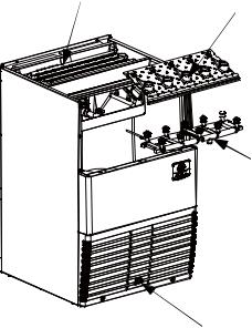
Component Identification
Water
Curtains
Water
 Trough
Control |
Air Cooled |
board |
Condenser |
|
On/Off/Wash-Fill |
|
Toggle Switch |
9
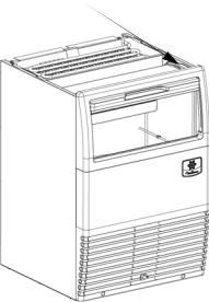
Evaporator
Ice Chute


 Spray
Spray
Nozzles
Spray Bar
Toggle Switch
10

COMPONENT REMOVAL
Top Cover
For easiest access to the evaporator compartment, the top cover can be removed.
1.Remove two screws on the rear of the ice machine.
2.Slide top cover back to disengage the three pins from the front panel
Remove 2 Screws and
Slide Cover Back
11
Bin Door
Allows access to the storage bin.
1.Remove top cover.
2.Slide door up until rear pins align with slot in door tracks.
3.Lift rear door pins out and slide door up until front door pins align with slot.
4.Lift door out of door track
Align Door Pins With
Track Slots, Then Lift
Door Out Of Track
12
Water Curtain
The water curtain is designed to keep the spraying water from escaping the evaporator compartment. Removal of the bin door is not required, but enhances access.
1.Grasp the ice curtain and lift up.
2.To re-install into ice machine, pivot the water curtain and pull down into position. Make sure tabs are secure in grooves.
Water Curtain
13
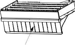
Ice Chute
The ice chute is positioned over the spray nozzles and allows the ice to easily fall into the bin. It must be firmly positioned over the Spray Bar Assembly, with the front edge inside the water trough or the spray nozzles will not be aligned with the spray holes, and spray water will fall into bin.
1.Grab protruding spray holes on one end and lift up.
2.Pivot ice chute and remove.
3.To re-install ice chute, grasp protruding spray holes and position over Spray Bar Assembly. Make sure rear supports are over Spray Bar Assembly, and front edge is inside of water trough
Ice Chute
14
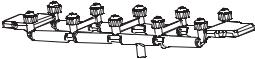
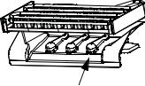
SPRAY BAR
The spray bar supplies water to the individual icemaking cups. Water from the Water Pump sprays through the nozzles, located on the upper portion of the tubes.
1.Grasp one end of the spray bar, lift up and remove from seat formed in water trough.
2.Remove both plastic clips on water inlet tubing by grasping both ears on clip and separating.
3.Apply food grade lubricate to ease re-assembly of spray bar components when necessary.
4.To re-install spray bar, position water inlet tubing on inlet ports, and squeeze clips until tight.
5.Reposition assembly on water trough seat.
NOTE: Nozzles and inserts can be removed for cleaning by unscrewing nozzles. Inserts are located inside the spray bar ports. The spray bar also disassembles for easy cleaning
15
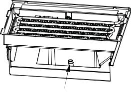
Sump Drain Overflow Tube
The sump drain overflow tube is located in the evaporator water sump.
1.Remove shutters and ice chute.
2.Lift spray bar or disconnect and remove for easiest access.
3.Pull up on over flow tube to remove.
To replace plug, insert in hole, and push with force to make a tight seal
Overflow Tube
16

Maintenance
INTERIOR CLEANING AND SANITIZING GENERAL
Clean and sanitize the ice machine every six months for efficient operation. If the ice machine requires more frequent cleaning and sanitizing, consult a qualified service company to test the water quality and recommend appropriate water treatment.
An extremely dirty ice machine must be taken apart for cleaning and sanitizing.
! Caution
Use only approved Ice Machine Cleaner and Sanitizer. Read and understand all labels printed on bottles before use. Do not mix Ice Machine Cleaner and Sanitizer solutions together
! Warning
Wear rubber gloves and safety goggles (and/or face shield) when handling Ice Machine Cleaner or Sanitizer.
17
CLEANING & SANITIZING PROCEDURE
Ice machine cleaner is used to remove lime scale or other mineral deposits. Sanitizer is used to remove algae or slime.
Mix 4 liters of water with 500 ml of cleaner in a plastic or stainless container.
Cleaner |
Water |
500 ml (16 oz) |
4 l (1 gal) |
Step 1 Set the toggle switch to the OFF position at the end of a Harvest Cycle, after ice releases from the evaporator. Or, set the switch to the OFF position and allow the ice to melt off the evaporator.
! Caution
Never use anything to force ice from the evaporator. Damage may result.
Step 2 Remove all ice from the bin.
Step 3 Remove all parts as described in Section 3, Component Identification & Removal.
Step 4 Take all components to sink and with 2 liters Cleaner/Water mixture clean all components with a soft nylon brush. Disassemble spray bar, remove nozzles and inserts and soak for 5 minutes. For heavily scaled parts, soak in solution for 15–20 minutes. Rinse all components with clean water.
Step 5 While components are soaking; use nylon brush to scrub inside of ice bin. Scrub inside of door, door track, bin, sump trough, and evaporator moldings. With clean water, rinse all of these areas thoroughly.
Step 6 Replace sump overflow tube and pour remaining 2 liters of mixture into the water sump. Replace all parts.
Step 7 To start a cleaning cycle, set the toggle switch to the WASH position.
18

Step 8 After 13.5 minutes, set the toggle switch to the OFF position. Remove water curtain, ice chute and over flow tube from the water sump. Allow all water to drain from the sump. Replace drain plug . Set toggle switch to WASH and circulate for 12minutes.
Step 9 Wait until the cleaning cycle(12 minutes) is complete then place the toggle switch in the OFF position.Remove water curtain, ice chute, water sump over flow tube. Drain water from sump and replace tube.
Step 10 Mix 60 ml of sanitizer with 12 l of water in a plastic or stainless steel container.
Sanitizer |
Water |
60 ml (2 oz) |
12 l (3 gal) |
Step 11 Remove Water Curtain and Ice Chute as described in Section 3, Component Identification & Removal.
Step 12 Take all components to sink and with 10 liters Sanitizer/Water mixture sanitize all components with a soft nylon brush or cloth. Do not rinse components.
Step 13 Use brush or cloth to sanitize the inside of ice bin. Scrub inside of door, door track, bin, water sump, water distribution assembly and evaporator moldings. Do not rinse.
Step 14 Replace sump drain over flow tube, and transfer remaining 2 liters of solution to the sump trough. Replace all components.
Step 15 To start a sanitizing cycle, set the toggle switch to the WASH position.
Step 16 After 13.5 minutes, set the toggle switch to the OFF position. Remove water curtain and ice chute Remove over flow tube from water sump and allow all water to drain from sump. Replace drain plug. Set toggle switch to WASH and circulate for 12 minutes.
Step 17 Wait until the cleaning cycle (12 minutes) is complete then place the toggle switch in the OFF
19
position. Remove water curtain, ice chute, water sump over flow tube. Drain water from sump and replace tub
Step 18 Replace all parts.
Step 19 Place toggle switch to ON position,ice machine will go into ice making cycle.
20
 Loading...