


 Loading...
 Manitowoc
R Model
Flake & Nugget
Technician’s
Handbook
This manual is updated as new information and models are released. Visit our website for the latest manual. www.manitowocice.com
America’s #1 Selling Ice Machine
Part Number 000007661 7/10

Read These Before Proceeding:
! Caution
Proper installation, care and maintenance are essential for maximum performance and troublefree operation of your Manitowoc equipment. If you encounter problems not covered by this handbook, do not proceed, contact Manitowoc Foodservice Group. We will be happy to provide assistance.
Important
Routine adjustments and maintenance procedures outlined in this handbook are not covered by the warranty.
! Warning
PERSONAL INJURY POTENTIAL
Do not operate equipment that has been misused, abused, neglected, damaged, or altered/modified from that of original manufactured specifications.
This appliance is not intended for use by persons (including children) with reduced physical, sensory or mental capabilities, or lack of experience and knowledge, unless they have been given supervision concerning use of the appliance by a person responsible for their safety.
We reserve the right to make product improvements at any time. Specifications and design are subject to change without notice.

Table of Contents
General Information
Model Numbers . . . . . . . . . . . . . . . . . . . . . 7 Self Contained
Air & Water-Cooled Models . . . . . . . . . 7 QuietQube Remote Air-cooled Models with Remote Condensing Units . . . . . . . . . 7
Model/Serial Number . . . . . . . . . . . . . . . . 8 Manitowoc Cleaner and Sanitizer . . . . . . 8 Ice Machine Warranty Information . . . . . 8
Installation
Location of Ice Machine . . . . . . . . . . . . . . 9 Installation Requirements . . . . . . . . . . . . 9 Potable Water Requirements . . . . . . . . . . 10
Drain Connections . . . . . . . . . . . . . . . . . . 10
Ice Machine Clearance Requirements . . 11
Cooling Tower Applications (Water-Cooled Models Only) . . . . . . . . . . 12
Heat of Rejection . . . . . . . . . . . . . . . . . . . 13 RF Models . . . . . . . . . . . . . . . . . . . . . . 13 RN Models . . . . . . . . . . . . . . . . . . . . . 13
Electrical Service . . . . . . . . . . . . . . . . . . . 13 Voltage . . . . . . . . . . . . . . . . . . . . . . . . 13 Fuse/Circuit Breaker . . . . . . . . . . . . . . 14 Ground Fault Interrupter Circuit (GFIC) 14
Maintenance
Cleaning and Sanitizing . . . . . . . . . . . . . . 15 Exterior Cleaning . . . . . . . . . . . . . . . . . 15 RF Models Cleaning/
Sanitizing Procedures . . . . . . . . . . . . . 16 RN Models Cleaning/
Sanitizing Procedure . . . . . . . . . . . . . . 22 Cleaning the Condenser . . . . . . . . . . . 24
Removal from Service/Winterization . . . 25
Part Number 000007661 7/10 |
3 |
Operation
Ice Making Sequence of Operation . . . . 27 Self-Contained Air-Cooled RF0244/RF0266/RF0385/ RF0388/RF0399 . . . . . . . . . . . . . . . . . 27 Self-Contained Air-Cooled
RF0300 . . . . . . . . . . . . . . . . . . . . . . . . 27 Self-Contained Air-Cooled RF0650/RF1200/RF2300 . . . . . . . . . . 28 QuietQube Remote Air-cooled Models with Remote Condensing Units RF1200C/RF2300C . . . . . . . . . . . . . . 29 Self-Contained Air-cooled & Water-Cooled RN0400 . . . . . . . . . . . . 30 Self-Contained Air-Cooled & Water-Cooled RN1000/RN1400 . . . . . 31 QuietQube Remote Air-cooled Models with Remote Condensing Units RN1000C/RN1200C . . . . . . . . . . . . . . 32
Thermostat Settings . . . . . . . . . . . . . . . . 34 RF Models . . . . . . . . . . . . . . . . . . . . . 34
Troubleshooting
Electrical Flowcharts . . . . . . . . . . . . . . . . 37
RF0244/RF0266RF0385//RF00388/ RF0399 Air & Water . . . . . . . . . . . . . . 38 RF0300 Air & Water . . . . . . . . . . . . . . 43 RF0650/RF1200 Air & Water . . . . . . . 48 RF2300 Air & Water . . . . . . . . . . . . . . 53 RN1000/RN1400 Air & Water . . . . . . . 60 RN1000C/RN1200C QuietQube . . . . . 68 RF1200C QuietQube . . . . . . . . . . . . . 78 RF2300C QuietQube . . . . . . . . . . . . . 84
Capillary Tube Models . . . . . . . . . . . . . . . 91 Thermostatic Expansion Valve Models . 92
4 |
Part Number 000007661 7/10 |
Component Specifications
Bin Thermostat . . . . . . . . . . . . . . . . . . 93 Low Temperature Thermostat . . . . . . . 93 High Pressure Cutout (HPCO) Control 93 Low Pressure Cutout (LPCO) Control . 94 Fan Cycle Control . . . . . . . . . . . . . . . . 94 Filter-Driers . . . . . . . . . . . . . . . . . . . . . 95 Suction Cleanup Filter-Drier . . . . . . . . 95 Total System Refrigerant Charge . . . . 96
Charts
Cycle Times/24-Hour Ice Production/ Refrigerant Pressure Charts . . . . . . . . . . 97
RF0244A . . . . . . . . . . . . . . . . . . . . . . . 98 RF0266A . . . . . . . . . . . . . . . . . . . . . . . 99 RF0385A . . . . . . . . . . . . . . . . . . . . . . . 100 RF0388A . . . . . . . . . . . . . . . . . . . . . . . 101 RF0399A . . . . . . . . . . . . . . . . . . . . . . . 102 RF0300A . . . . . . . . . . . . . . . . . . . . . . . 103 RF0650A . . . . . . . . . . . . . . . . . . . . . . . 104 RF1200A . . . . . . . . . . . . . . . . . . . . . . . 105 RF1200W . . . . . . . . . . . . . . . . . . . . . . 106 RF2300A . . . . . . . . . . . . . . . . . . . . . . . 107 RF2300W . . . . . . . . . . . . . . . . . . . . . . 108 RN1000A . . . . . . . . . . . . . . . . . . . . . . . 109 RN1000W . . . . . . . . . . . . . . . . . . . . . . 110 RN1400A . . . . . . . . . . . . . . . . . . . . . . . 111 RN1400W . . . . . . . . . . . . . . . . . . . . . . 112 RN1078C . . . . . . . . . . . . . . . . . . . . . . 113 RN1278C . . . . . . . . . . . . . . . . . . . . . . 114 RF1278C . . . . . . . . . . . . . . . . . . . . . . . 115 RF2378C . . . . . . . . . . . . . . . . . . . . . . . 116
Part Number 000007661 7/10 |
5 |
Diagrams
Wiring Diagrams . . . . . . . . . . . . . . . . . . . 117 RF0244/RF0266/RF0385/ RF0388/RF0399 Air-Cooled . . . . . . . . 118 RF0300 Air-Cooled . . . . . . . . . . . . . . . 120 RF0650 - RF1200 Air-Cooled . . . . . . . 122 RF1200 Water-Cooled . . . . . . . . . . . . 124 RF2300 Air-Cooled & Water-cooled . . 126 RN1000/RN1400 Air & Water Cooled 128 RN1000C QuietQube Head Section . . 129 RN1200C QuietQube Head Section . . 130 RN2300C QuietQube Head Section . . 132 RCU Condensing Unit 1ph . . . . . . . . . 134 RCU Condensing Unit 3ph . . . . . . . . . 135
Refrigeration Tubing Schematics . . . . . 136 RF0244/RF0266/RF0388/RF0399 RF0300/RF0650 Air-cooled . . . . . . . . 136 RF1200 Air-cooled . . . . . . . . . . . . . . . 138 RF1200 Water-cooled . . . . . . . . . . . . 140 RF2300 Air-cooled . . . . . . . . . . . . . . . 142 RF2300 Water-cooled . . . . . . . . . . . . 144 RN1000/RN1400 Air & Water-cooled . 146 RN1000C QuietQube Head Section & RCU1075 Condensing Unit . . . . . . . . 148 RN1200C QuietQube Head Section & RCU1275 Condensing Unit . . . . . . . . 150 RN2300C QuietQube Head Section & RCU2375 Condensing Unit . . . . . . . . 152
6 |
Part Number 000007661 7/10 |

General Information
Model Numbers
SELF CONTAINED
AIR & WATER-COOLED MODELS
Flake Models |
|
|
|
|
|
Self Storage |
|
Self Storage |
Modular |
Modular |
|
|
Water- |
||||
Air-Cooled |
|
Water-Cooled |
Air-Cooled |
||
|
Cooled |
||||
|
|
|
|
|
|
RF0244A |
|
– |
– |
– |
|
RF0266A |
|
– |
– |
– |
|
RF0385A |
|
– |
– |
– |
|
RF0388A |
|
– |
– |
– |
|
RF0399A |
|
– |
– |
– |
|
– |
|
– |
RF0300A |
– |
|
– |
|
– |
RF0650A |
– |
|
– |
|
– |
RF1200A |
– |
|
– |
|
– |
RF2300A |
– |
|
Nugget Models |
|
|
|||
Self Storage |
|
Self Storage |
Modular |
Modular |
|
|
Water- |
||||
Air-Cooled |
|
Water-Cooled |
Air-Cooled |
||
|
Cooled |
||||
|
|
|
|
|
|
– |
|
– |
RN1008A |
RN1009W |
|
– |
|
– |
RN1408A |
RN1409W |
|
QUIETQUBE REMOTE AIR-COOLED MODELS |
|||||
WITH REMOTE CONDENSING UNITS |
|
||||
Flake Models |
|
|
|
|
|
QuietQube Head |
|
RCU Remote |
|||
|
Condensing Unit |
||||
|
|
|
|
||
RF1278C |
|
RCU1275 |
|||
RF2378C |
|
RCU2375 |
|||
Nugget Models |
|
|
|
||
QuietQube Head |
|
RCU Remote |
|||
|
Condensing Unit |
||||
|
|
|
|
||
RN1078C |
|
RCU1075 |
|||
RN1278C |
|
RCU1275 |
|||
Part Number 000007661 7/10 |
7 |
Model/Serial Number
These numbers are required when requesting information from your local Manitowoc Distributor, or Manitowoc Ice. The model and serial number are listed on the MODEL/SERIAL NUMBER DECAL affixed to the ice machine.
Manitowoc Cleaner and Sanitizer
Manitowoc Ice Machine Cleaner and Sanitizer are available in 16 oz. (473 ml) bottles. These are the only cleaners and sanitizers approved for use with Manitowoc products.
Cleaner Part Number |
Sanitizer Part Number |
||
16 oz. |
000000084 |
16 oz. |
9405653 |
1 gal |
N/A |
1 gal. |
9405813 |
Ice Machine Warranty Information
Warranty information for all ice machine models is available on our website at www.manitowocice.com.
8 |
Part Number 000007661 7/10 |

Installation
Location of Ice Machine
The location selected for the ice machine must meet the following criteria. If any of these criteria are not met, select another location.
•The location must be free of airborne and other contaminants.
•The location must not be near heat-generating equipment or in direct sunlight.
•The location must be capable of supporting the weight of the ice machine and a full bin of ice.
•The location must allow enough clearance for water, drain and electrical connections in the rear of the ice machine.
•The location must not obstruct airflow through or around the ice machine.
Installation Requirements
•The air temperature must be at least 50°F (10°C), but must not exceed 110°F (43°C).
•The water temperature must be at least 40°F (4°C), but must not exceed 90°F (32°C).
•The ice machine and bin must be level.
•Vent the ice machine and bin drains separately.
•Bin drain termination must have an air gap.
•RF Models Only: A backflow preventer is required on water inlet lines.
•Routine adjustments and maintenance procedures outlined in this manual are not covered by the warranty.
Part Number 000007661 7/10 |
9 |
Potable Water Requirements
•Plumbing must conform to local codes.
•Do not connect the ice machine to a hot water supply. Be sure all hot water restrictors installed for other equipment are working. (Check valves on sink faucets, dishwashers, etc.)
•If water pressure exceeds maximum pressure (70 psig [483 kPa] RN1000; 80 psig [552 kPa] for all other models) obtain a water pressure regulator from your Manitowoc distributor.
•A water shut-off valve is required to clean the ice machine.
•A union for both the ice making and condenser water lines is required.
•Water inlet lines require insulation to prevent condensation.
•RF Models: A backflow preventer is required on water inlet lines.
Drain Connections
•Drain lines must have a 1.5 inch drop per 5 feet of run (2.5 cm per meter), and must not create traps.
•The floor drain must be large enough to accommodate drainage from all drains.
•Separate insulated bin and water-cooled condenser drain lines are required.
•The bin and ice machine drains require a vent.
10 |
Part Number 000007661 7/10 |
Ice Machine Clearance Requirements
Head |
Self- |
|
Self- |
QuietQube |
|
Contained |
|
Contained |
|||
Sections |
|
Air-Cooled |
|||
Air-Cooled |
Water-Cooled* |
||||
|
|
||||
Back |
5" (12.7 cm) |
|
5" (12.7 cm) |
0" (0 cm) |
|
Sides/Top |
8" (20.3 cm) |
|
8" (20.3 cm) |
0" (20 cm) |
|
|
|
|
|||
RCU Units |
|
Remote Condensing Unit* |
|||
Front/Back |
|
24" (61.0 cm) |
|||
Sides/Top |
|
6" (15.2 cm)* |
|||
*Water-Cooled Only - There is no minimum clearance required. This value is recommended for efficient operation and servicing only.
NOTE: Allowance must be made for removal when the ice machine is built-in. Monthly removal of the top panel is required for cleaning and sanitizing.
Part Number 000007661 7/10 |
11 |
Cooling Tower Applications
(Water-Cooled Models Only)
A water cooling tower installation does not require modification of the ice machine. The water regulator valve for the condenser continues to control the refrigeration discharge pressure.
It is necessary to know the amount of heat rejection, and pressure drop through the condenser and water valves (inlet and outlet) when using a cooling tower on an ice machine.
•Water entering the condenser must not be lower than 37°F (3°C) or exceed 90°F (32°C).
•Water flow through the condenser must not exceed 5 gal. (19 L) per minute.
•Allow for a pressure drop of 7 psi (48 kPa) between the condenser water inlet and the outlet of the ice machine.
•Water exiting the condenser must not exceed 110°F (43°C).
12 |
Part Number 000007661 7/10 |

Heat of Rejection
RF MODELS
Model |
Heat of Rejection 1 |
|
RF0244 |
2,400 |
BTUH (605 Kcal/hr) |
RF0266 |
2,400 |
BTUH (605 Kcal/hr) |
RF0385 |
3,500 |
BTUH (882 Kcal/hr) |
RF0388 |
3,500 |
BTUH (882 Kcal/hr) |
RF0399 |
3,500 |
BTUH (882 Kcal/hr) |
RF0300 |
3,500 |
BTUH (882 Kcal/hr) |
RF0650 |
7,700 BTUH (1941 Kcal/hr) |
|
RF1200 |
14,000 |
BTUH (3529 Kcal/hr) |
RF2300 |
29,500 |
BTUH (7436 Kcal/hr) |
RN MODELS
Series |
Heat of Rejection 1 |
||
Ice Machine |
Air-Cooled |
Water-Cooled |
|
RN1000 - 50/60 Hz |
11,300 BTU/hr |
12,800 BTU/hr |
|
(2848 Kcal/hr) |
(3226 Kcal/hr) |
||
|
|||
RN1400 - 50 Hz |
16,000 BTU/hr |
16,400 BTU/hr |
|
(4032 Kcal/hr) |
(4133 Kcal/hr) |
||
|
|||
RN1400 - 60 Hz |
15,500 BTU/hr |
15,500 BTU/hr |
|
(3906 Kcal/hr) |
(3906 Kcal/hr) |
||
|
|||
1 The figure shown is an average.
Electrical Service
! Warning
All wiring must conform to local, state and national codes.
VOLTAGE
The maximum allowable voltage variation is ± 10% of the rated voltage on the ice machine model/serial number plate at compressor start-up.
Part Number 000007661 7/10 |
13 |
FUSE/CIRCUIT BREAKER
A separate fuse/circuit breaker must be provided for each ice machine. Circuit breakers must be H.A.C.R. rated (does not apply in Canada).
! Warning
The ice machine must be grounded in accordance with national and local electrical codes.
GROUND FAULT INTERRUPTER CIRCUIT (GFIC)
A GFCI/GFI circuit protection is not recommended with our equipment. If a GFCI/GFI is required by code a GFCI/GFI breaker rather than outlet must be used to avoid intermittent nuisance trips.
14 |
Part Number 000007661 7/10 |
Maintenance
Cleaning and Sanitizing
Maintenance procedures covered in this manual are not covered by the warranty.
! Caution
Use only Manitowoc approved Ice Machine Cleaner (part number 000000084) and Sanitizer (part number 9405653). Do not mix Cleaner and Sanitizer solutions together. It is a violation of Federal law to use these solutions in a manner inconsistent with their labeling. Read and understand all labels printed on bottles before use.
! Warning
Wear rubber gloves and safety goggles (and/or face shield) when handling ice machine Cleaner or Sanitizer.
EXTERIOR CLEANING
Remove dust and dirt off exterior surfaces with mild household dish-washing detergent and warm water. Wipe dry with a clean, soft cloth.
Part Number 000007661 7/10 |
15 |
RF MODELS CLEANING/SANITIZING PROCEDURES
Cleaning/Sanitizing Procedure
This procedure must be performed once every month.
•All ice must be removed from the bin
•The ice machine and bin must be disassembled cleaned and sanitized
•The ice machine produces ice with the cleaner and sanitizer solutions
•All ice produced during the cleaning and sanitizing procedure must be discarded
Procedure to Clean/Sanitize
Use Ice Machine Cleaner part number 000000084. Use Ice Machine Sanitizer part number 9405653.
Step 1 Remove front and top covers and set the toggle switch to the OFF position.
Step 2 Remove all ice from the bin.
Step 3 Turn off the ice making water supply and drain water from evaporator and reservoir.
Step 4 Remove the top cover from water reservoir.
Step 5 Follow the chart and premix cleaner and water.
Amount of Water |
Amount of Cleaner |
|
Part Number 000000084 |
||
|
||
1 gallon (4 Liters) |
3 ounces (90 ml) |
16 |
Part Number 000007661 7/10 |
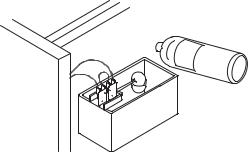
Step 6 Fill the evaporator and reservoir with cleaning solution.
Prop Float Up to Prevent Low
Water Level Shutdown
Step 7 Move the toggle switch to the ON position. The ice machine will make ice with the cleaning solution and deposit the ice in the bin. Add the remaining cleaner/water solution as the water level in the reservoir drops.
NOTE: Do not allow the cleaner/water level to drop below the minimum water level. The ice machine will discontinue the cleaning cycle if the water float switch opens.
Step 8 After all of the cleaner/water solution has been added turn on the ice making water supply. Continue the freeze cycle for 10 minutes to remove the cleaning solution from the water circuit.
Part Number 000007661 7/10 |
17 |
Step 9 Place the toggle switch in the OFF position.
Step 10 Refer to disassembly for cleaning/sanitizing and remove parts for hand cleaning/sanitizing.
•Hand clean all parts
•Rinse all parts with clear potable water
•Sanitize all parts - do not rinse after sanitizing
•Spray all interior bin surfaces with sanitizer (do not rinse sanitized areas).
•Spray evaporator discharge spout
Step 11 Reassemble ice machine.
Step 12 Turn off the ice making water supply.
18 |
Part Number 000007661 7/10 |
Step 13 Refer to chart and premix water and sanitizer.
Amount of Water |
Amount of Sanitizer |
1 Gallons (4 L) Water |
1/2 ounce (15 ml) |
Step 14 Fill the evaporator and reservoir with sanitizer/water solution.
Step 15 Move the toggle switch to the ON position. The ice machine will make ice with the sanitizer/water solution and deposit the ice in the bin. Add the remaining sanitizer/water solution when the water level in the reservoir drops.
NOTE: Do not allow the sanitizer/water level to drop below the minimum water level. The ice machine will discontinue the cleaning cycle if the water float switch opens.
Step 16 After all of the sanitizer/water solution has been added to the reservoir, turn on the ice making water supply.
Step 17 Continue the freeze cycle for 30 minutes and then discard all ice produced.
Part Number 000007661 7/10 |
19 |
Heavily Scaled Cleaning Procedure
Perform this procedure if you have some or all of these symptoms.
•Excessive grinding, popping or squealing noises from the evaporator
•Grinding noise from gearbox
•Ice machine trips speed sensor
NOTE: A Cleaning/Sanitizing Procedure must be performed after this procedure.
Procedure to Clean Heavily Scaled Flake Ice Machines
Step 1 Remove front and top covers and set the toggle switch to the OFF position.
Step 2 Remove all ice from the bin.
Step 3 Turn off the ice making water supply.
Step 4 Remove the top cover from water reservoir.
20 |
Part Number 000007661 7/10 |
Step 5 Refer to chart below:
Premix cleaner with lukewarm water in a non-metallic container.
|
|
Mix Cleaner and Water |
||
|
Water |
Use Ice machine nickel safe |
||
|
cleaner, part number |
|||
Model |
Reservoir |
|||
000000084 only |
||||
|
Capacity |
|||
|
|
|
||
|
|
Cleaner |
Water |
|
|
|
|
|
|
RF0244 |
|
|
|
|
RF0266 |
|
|
|
|
RF0385 |
14 oz (400 ml) |
9 oz (266 ml) |
5 oz (148 ml) |
|
RF0388 |
|
|
|
|
RF0399 |
|
|
|
|
|
|
|
|
|
RF0300 |
17 oz (500 ml) |
11 oz (325 ml) |
6 oz (177 ml) |
|
RF0650 |
||||
|
|
|
||
|
|
|
|
|
RF1200 |
34 oz (1 L) |
23 oz (680 ml) |
11 oz (325 ml) |
|
|
|
|
|
|
RF2300 |
68 oz (2 L) |
46 oz (1.3 L) |
22 oz (650 ml) |
|
|
|
|
|
|
Step 6 Remove all water from the evaporator and water reservoir. Add the entire cleaner/water solution and re-install the reservoir cover.
Leave the cleaner/water solution in the evaporator for a minimum of 4 hours.
Step 7 Remove all cleaner/water from the evaporator and water reservoir.
Step 8 Follow the standard cleaning and sanitizing procedures.
Part Number 000007661 7/10 |
21 |
RN MODELS CLEANING/SANITIZING PROCEDURE
Use Ice Machine Cleaner part number 000000084. Use Ice Machine Sanitizer part number 94-0565-3. Step 1 Remove all ice from the bin/dispenser.
Step 2 Remove front and top covers. Step 3 Mix a solution of cleaner and water.
Amount of |
Amount of Cleaner |
Luke Warm Water |
Part Number 000000084 |
1 gallon (4 Liters) |
4 ounces (120 ml) |
Step 4 To start a cleaning cycle, depress the CLEAN switch to drain the water from the evaporator. Wait for the LOW WATER light to energize.
Step 5 Remove cover from the cleaning cup and add cleaner/water solution until the HI WATER light energizes, then replace cleaning cup cover. The machine will clean and then flush three times in approximately twelve minutes.
Step 6 While the ice machine is in the clean cycle, prepare for the sanitizing cycle by mixing a solution of sanitizer and water.
Amount of |
Amount of Sanitizer |
Luke Warm Water |
Part Number 94-0565-3 |
1 gallon (4 L) Water |
1/2 ounce (15 ml) |
Step 7 To start a sanitize cycle, depress the clean switch to drain the water from the evaporator. Wait for the LOW WATER light to energize.
Step 8 Remove cover from the cleaning cup and add sanitizer/water solution until the HI WATER light energizes, then replace cleaning cup cover. The machine will sanitize and then flush three times in approximately twelve minutes.
22 |
Part Number 000007661 7/10 |
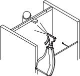
Step 9 Press the OFF switch, then unscrew the ice chute connector.
Step 10 Using disposable food service grade gloves insert one dry sponge into the transport tube going to the evaporator (NOT the tube going to the bin), then insert one sponge soaked in the sanitizer water solution. With the pusher tube supplied with the sponge kit, push sponges all the way down the transport tube 16 inches (41 cm) or the length of the pusher tube.
Step 11 Reconnect chute connector and press the ON switch. Allow the ice machine to run for 10 minutes, then press the OFF switch. Catch and remove all sponges and ice from the bin/dispenser.
Step 12 Clean and sanitize the bin/dispenser:
•Disconnect power to the dispenser to prevent injury.
•Use the cleaner and sanitizer ratios from the charts on the previous page.
•Heavy accumulations of scale will require removal of components for cleaning and sanitizing.
•Rinse parts with clear water after cleaning - do not rinse parts after sanitizing.
Step 13 Spray all interior bin/dispenser surfaces with sanitizer (do not rinse sanitized areas).
Step 14 Place rocker switch in the ON position and reinstall all removed panels.
1.Lift out ice damper.
2.Remove ice deflector.
A. Remove the two thumbscrews.
Part Number 000007661 7/10 |
23 |

CLEANING THE CONDENSER
! Warning
Disconnect electric power to the ice machine at the electric service switch before cleaning the condenser. The condenser fins are sharp. Use care when cleaning them.
Air-Cooled Condenser
Clean the condenser at least every six months. Follow the steps below.
1.Some models have a washable aluminum filter. Clean the filter with a mild soap and water solution.
2.Shine a flashlight through the condenser to check for dirt between the fins. Blow compressed air through the condenser fins from the inside or use a commercial condenser coil cleaner. Follow the directions and cautions supplied with the cleaner.
3.Straighten any bent condenser fins with a fin comb.
4.Carefully wipe off the fan blades and motor with a soft cloth. Do not bend the fan blades. If the fan blades are excessively dirty, wash with warm, soapy water and rinse thoroughly.
! Warning
If you are cleaning the condenser fan blades with water, cover the fan motor to prevent water damage.
24 |
Part Number 000007661 7/10 |

Removal from Service/Winterization
! Caution
If water is allowed to remain in the ice machine in freezing temperatures, severe damage to some components could result. Damage of this nature is not covered by the warranty.
Follow the procedure below.
1.Disconnect the electric power at the circuit breaker or the electric service switch.
2.Turn off the water supply.
3.Disconnect and drain the incoming ice-making water line at the rear of the ice machine.
4.Disconnect drain tubing and drain water into container and discard.
5.Make sure water is not trapped in any of the water or drain lines.
6.Water cooled - Use compressed air to remove all water from the condenser.
Part Number 000007661 7/10 |
25 |
This Page Intentionally Left Blank
26 |
Part Number 000007661 7/10 |

Operation
Ice Making Sequence of Operation
NOTE: Flake ice machines use an auger to remove ice from the evaporator. Occasional noises (creaks, groans, squeaks, or pops) are a normal part of the ice making process.
SELF-CONTAINED AIR-COOLED RF0244/RF0266/RF0385/RF0388/RF0399
When the toggle switch is placed in the “ON” position the following controls must be in the closed position before the ice machine will start:
A.Bin Thermostat
B.Low Evaporator Temperature Thermostat
C.Low Water Level Switch
Placing the toggle switch in the ON position starts the gear motor and refrigeration system. The float valve controls the water inlet valve and water level. The freeze cycle ends when ice contacts the bin thermostat. The ice machine will restart when ice no longer contacts the bin thermostat.
SELF-CONTAINED AIR-COOLED RF0300
When the toggle switch is placed in the “ON” position the following controls must be in the closed position before the ice machine will start:
A.Bin Thermostat
B.Low Evaporator Temperature Thermostat
C.Ice Chute Safety Switch
D.Low Water Level Switch
Placing the toggle switch in the ON position starts the gear motor and a 10 minute compressor time delay. The compressor starts and the float valve controls the water inlet valve and water level. The freeze cycle ends when ice contacts the bin thermostat. The ice machine remains off until ice no longer contacts the bin thermostat.
Part Number 000007661 7/10 |
27 |
SELF-CONTAINED AIR-COOLED RF0650/RF1200/RF2300
When the toggle switch is placed in the ON position the following controls must be in the closed position before the ice machine will start:
A.Bin Thermostat
B.High Pressure Cut-out Switch
C.Ice Chute Safety Switch
D.Low Pressure Switch
E.Low Water Level Switch
Placing the toggle switch in the ON position starts the gear motor. After the rotation speed sensor verifies 10 minutes of correct rotation the time delay ends and the compressor starts.The ice machine will continue to make ice until ice contacts the bin thermostat. The ice machine remains off until ice no longer contacts the bin thermostat.
28 |
Part Number 000007661 7/10 |
QUIETQUBE REMOTE AIR-COOLED MODELS WITH REMOTE CONDENSING UNITS RF1200C/RF2300C
Part Number 000007661 7/10 |
29 |
SELF-CONTAINED AIR-COOLED & WATER-COOLED
RN0400
NOTE: Ice machines use an auger to remove ice from the evaporator. Occasional noises (creaks, groans, squeaks, or pops) are a normal part of the ice making process.
Operation
The ice machine will not start until:
A.The compressor rocker switch is moved to “ON”.
B.Ice does not contact the bin thermostat bulb.
C.The water reservoir is full of water.
With power supplied and the compressor rocker switch in the ON position, the gear motor and refrigeration system start. The float valve controls the water inlet valve and water level. The freeze cycle ends when ice contacts the bin thermostat. A
20 minute delay period initiates. The ice machine will restart when ice no longer contacts the bin thermostat and the 20 minute delay period expires.
30 |
Part Number 000007661 7/10 |
Loading...