


 Loading...
CounterTop Nugget Ice Machines
RNS12 / RNS20 Models
Installation, Operation and Maintenance Manual
This manual is updated as new information and models are released. Visit our website for the latest manual.
Part Number: 000008276 10/13

Table of Contents
Section 1 |
|
General Information |
|
Model Numbers . . . . . . . . . . . . . . . . . . . . . . . . . . . . . . . . . . . . . . . . . . . . . . . . . . . . . |
4 |
Accessories . . . . . . . . . . . . . . . . . . . . . . . . . . . . . . . . . . . . . . . . . . . . . . . . . . . . . . . |
4 |
Manitowoc Cleaner and Sanitizer . . . . . . . . . . . . . . . . . . . . . . . . . . . . . . . . . . . |
4 |
Legs . . . . . . . . . . . . . . . . . . . . . . . . . . . . . . . . . . . . . . . . . . . . . . . . . . . . . . . . . . |
4 |
Touchless Sensing Option . . . . . . . . . . . . . . . . . . . . . . . . . . . . . . . . . . . . . . . . . |
4 |
Section 2 |
|
Installation Instructions |
|
Location of Ice Machine . . . . . . . . . . . . . . . . . . . . . . . . . . . . . . . . . . . . . . . . . . . . . . |
5 |
Ice Machine Clearance Requirements . . . . . . . . . . . . . . . . . . . . . . . . . . . . . . . . . . |
5 |
Electrical Service . . . . . . . . . . . . . . . . . . . . . . . . . . . . . . . . . . . . . . . . . . . . . . . . . . . |
6 |
Voltage . . . . . . . . . . . . . . . . . . . . . . . . . . . . . . . . . . . . . . . . . . . . . . . . . . . . . . . |
6 |
Fuse/Circuit Breaker . . . . . . . . . . . . . . . . . . . . . . . . . . . . . . . . . . . . . . . . . . . . . |
6 |
Total Circuit Ampacity . . . . . . . . . . . . . . . . . . . . . . . . . . . . . . . . . . . . . . . . . . . . |
6 |
Electrical Requirements . . . . . . . . . . . . . . . . . . . . . . . . . . . . . . . . . . . . . . . . . . . . . . |
6 |
Water Supply and Drains . . . . . . . . . . . . . . . . . . . . . . . . . . . . . . . . . . . . . . . . . . . . . |
6 |
Potable Water Supply . . . . . . . . . . . . . . . . . . . . . . . . . . . . . . . . . . . . . . . . . . . . |
6 |
Potable Water Inlet Lines . . . . . . . . . . . . . . . . . . . . . . . . . . . . . . . . . . . . . . . . . . |
6 |
Drain Connections . . . . . . . . . . . . . . . . . . . . . . . . . . . . . . . . . . . . . . . . . . . . . . . |
6 |
Water Supply and Drain Line Sizing/Connections . . . . . . . . . . . . . . . . . . . . . . . |
7 |
Before Starting the Ice Machine . . . . . . . . . . . . . . . . . . . . . . . . . . . . . . . . . . . . . . . |
8 |
Installation Checklist . . . . . . . . . . . . . . . . . . . . . . . . . . . . . . . . . . . . . . . . . . . . . |
8 |
Section 3 |
|
Operation |
|
Sequence of Operation . . . . . . . . . . . . . . . . . . . . . . . . . . . . . . . . . . . . . . . . . . . . . . |
9 |
15 Minute Time Delay . . . . . . . . . . . . . . . . . . . . . . . . . . . . . . . . . . . . . . . . . . . . |
9 |
Prior to Start-up . . . . . . . . . . . . . . . . . . . . . . . . . . . . . . . . . . . . . . . . . . . . . . . . . |
9 |
Initial Start-up . . . . . . . . . . . . . . . . . . . . . . . . . . . . . . . . . . . . . . . . . . . . . . . . . . |
9 |
Freeze Cycle . . . . . . . . . . . . . . . . . . . . . . . . . . . . . . . . . . . . . . . . . . . . . . . . . . . |
9 |
Automatic Shut-off . . . . . . . . . . . . . . . . . . . . . . . . . . . . . . . . . . . . . . . . . . . . . . . |
9 |
Restart After Automatic Shut-off . . . . . . . . . . . . . . . . . . . . . . . . . . . . . . . . . . . . |
9 |
Operational Checks . . . . . . . . . . . . . . . . . . . . . . . . . . . . . . . . . . . . . . . . . . . . . . . . . |
10 |
General . . . . . . . . . . . . . . . . . . . . . . . . . . . . . . . . . . . . . . . . . . . . . . . . . . . . . . . |
10 |
Operation . . . . . . . . . . . . . . . . . . . . . . . . . . . . . . . . . . . . . . . . . . . . . . . . . . . . . . |
10 |
2 |
Part Number 000008276 10/13 |

Table of Contents (continued)
Section 4 Maintenance
Cleaning and Sanitizing . . . . . . . . . . . . . . . . . . . . . . . . . . . . . . . . . . . . . . . . . . . . . 11 General . . . . . . . . . . . . . . . . . . . . . . . . . . . . . . . . . . . . . . . . . . . . . . . . . . . . . . . 11 Exterior Cleaning . . . . . . . . . . . . . . . . . . . . . . . . . . . . . . . . . . . . . . . . . . . . . . . 11 Procedures . . . . . . . . . . . . . . . . . . . . . . . . . . . . . . . . . . . . . . . . . . . . . . . . . . . . 11 Preventative Maintenance Cleaning Procedure . . . . . . . . . . . . . . . . . . . . . . . . 12 Procedure to Clean Heavily Scaled Flake/Nugget Ice Machines . . . . . . . . . . . 13 Cleaning Procedure . . . . . . . . . . . . . . . . . . . . . . . . . . . . . . . . . . . . . . . . . . . . . 13 Sanitizing Procedure . . . . . . . . . . . . . . . . . . . . . . . . . . . . . . . . . . . . . . . . . . . . . 14
Component Disassembly for Cleaning/Sanitizing . . . . . . . . . . . . . . . . . . . . . . . . 15 Cleaning the Condenser . . . . . . . . . . . . . . . . . . . . . . . . . . . . . . . . . . . . . . . . . . . . . 18 Removal from Service/Winterization . . . . . . . . . . . . . . . . . . . . . . . . . . . . . . . . . . . 19 General . . . . . . . . . . . . . . . . . . . . . . . . . . . . . . . . . . . . . . . . . . . . . . . . . . . . . . . 19
Section 5
Customer Support
Checklist . . . . . . . . . . . . . . . . . . . . . . . . . . . . . . . . . . . . . . . . . . . . . . . . . . . . . . . . . . 20
Flake/Chiplet/Nugget Commercial Ice Machine Warranty . . . . . . . . . . . . . . . . . . 21
Residential Ice Machine Limited Warranty . . . . . . . . . . . . . . . . . . . . . . . . . . . . . . 22
Part Number 000008276 10/13 |
3 |

Section 1
General Information
Model Numbers
This manual covers the following models:
Lever Activated |
Touchless Sensor |
|
Activated |
||
|
||
RNS12A |
RNS12AT |
|
Self Contained Air-Cooled |
Self Contained Air-Cooled |
|
Nugget Ice Machine |
Nugget Ice Machine |
|
RNS20A |
RNS20AT |
|
Self Contained Air-Cooled |
Self Contained Air-Cooled |
|
Nugget Ice Machine |
Nugget Ice Machine |
|
|
RNS20ATS |
|
N/A |
Self Contained Air-Cooled |
|
|
Nugget Ice Machine |
! Warning
Do not operate equipment that has been misused, abused, neglected, damaged, or altered/modified from that of original manufactured specifications.
This appliance is not intended for use by persons (including children) with reduced physical, sensory or mental capabilities, or lack of experience and knowledge, unless they have been given supervision concerning use of the appliance by a person responsible for their safety.
Accessories
MANITOWOC CLEANER AND SANITIZER
Manitowoc Ice Machine Cleaner and Sanitizer are available in convenient 16 oz. (473 ml) and 1 gal (3.78 l) bottles. These are the only cleaner and sanitizer approved for use with Manitowoc products.
Cleaner Part Number |
Sanitizer Part Number |
||
16 oz. |
000000084 |
16 oz. |
94-0565-3 |
1 Gallon |
94-0581-3 |
||
LEGS
Optional four inch adjustable legs are available.
TOUCHLESS SENSING OPTION
Touchless sensing can be ordered installed on the ice machine from the factory or a field conversion kit is available. The field conversion kit includes a replacement front panel and instructions for installation.
4 |
Part Number 000008276 10/13 |

Section 2
Installation Instructions
These instructions are provided to assist the qualified installer. Check your local Yellow Pages for the name of the nearest Manitowoc distributor, or call Manitowoc Foodservice for information regarding start-up services.
Important
Failure to follow these installation guidelines may affect warranty coverage.
Location of Ice Machine
The location selected for the ice machine must meet the following criteria. If any of these criteria are not met, select another location.
•The location must be free of airborne and other contaminants.
•The air temperature must be at least 45°F (7°C), but must not exceed 110°F (43°C).
•The water temperature must be at least 45°F (7°C), but must not exceed 90°F (32°C).
•The location must not be near heat-generating equipment or in direct sunlight.
•The location must be capable of supporting the weight of the ice machine and a full bin of ice and allow the ice machine to be level front to back and side to side.
•The location must allow enough clearance for water and electrical connections in the rear of the ice machine. The drain can be routed out the rear or bottom of dispenser.
•The location must not obstruct airflow through or around the ice machine. Airflow is in the left side and out the top. Refer to chart for clearance requirements.
These ice machines are intended for use in household and similar applications such as:
•Staff kitchen areas in shops, offices and other work environments.
•Clients in hotels, motels, farmhouses, bed and breakfast and other residential type environments.
•Catering and similar non-retail applications.
! Warning
To avoid instability the ice machine must be installed in an area capable of supporting the weight of the ice machine and a full bin of ice.
Ice Machine Clearance Requirements
|
RNS12 |
RNS20 |
Top |
24" (61 cm) |
24" (61 cm) |
Sides |
8" (20 cm) |
8" (20 cm) |
Back* |
5" (13 cm) |
5" (13 cm) |
* - 5" (13 cm) is recommended for servicing the ice machine. Clearance can be 0" when water and drain connections exit the bottom of the ice machine.
! Caution
The ice machine head section must be protected if it will be subjected to temperatures below 32°F (0°C). Failure caused by exposure to freezing temperatures is not covered by the warranty. See “Removal from Service/Winterization”.
Part Number 000008276 10/13 |
5 |
Installation Instructions |
Section 2 |
|
|
Electrical Service
! Warning
All wiring must conform to local, state and national codes.
VOLTAGE
The maximum allowable voltage variation is ±10% of the rated voltage on the ice machine model/serial number plate at start-up (when the electrical load is highest).
FUSE/CIRCUIT BREAKER
A separate fuse/circuit breaker must be provided for each ice machine. Circuit breakers must be H.A.C.R. rated (does not apply in Canada).
115/60/1 ice machines are factory pre-wired with a power cord and 5-15P plug.
230/50/1 ice machines are factory pre-wired with a power cord, no plug is supplied.
! Warning
The ice machine must be grounded in accordance with national and local electrical codes.
! Warning
PERSONAL INJURY POTENTIAL
If the supply cord is damaged, do not operate the equipment until the cord is replaced by a service agent or similarly qualified person.
TOTAL CIRCUIT AMPACITY
The total circuit ampacity is used to help select the wire size of the electrical supply.
The wire size (or gauge) is also dependent upon location, materials used, length of run, etc., so it must be determined by a qualified electrician.
Electrical Requirements
|
Voltage |
Air-Cooled |
|
Ice Machine |
Total |
||
Phase |
|||
Circuit |
|||
|
Cycle |
||
|
Amps |
||
|
|
||
RNS12 |
115/1/60 |
10.3 amps |
|
RNS20 |
230/1/50 |
5.4 amps |
Water Supply and Drains
POTABLE WATER SUPPLY
Local water conditions may require treatment of the water to inhibit scale formation, filter sediment, and remove chlorine odor and taste.
! Warning
PERSONAL INJURY POTENTIAL
For ice making, connect to a potable water supply only.
Important
If you are installing a Manitowoc water filter system, refer to the Installation Instructions supplied with the filter system for ice making water inlet connections.
POTABLE WATER INLET LINES
Follow these guidelines to install water inlet lines:
•Do not connect the ice machine to a hot water supply. Be sure all hot water restrictors installed for other equipment are working. (Check valves on sink faucets, dishwashers, etc.)
•If water pressure exceeds the maximum (80 psig/ 551.5 kPA) recommended pressure, obtain a water pressure regulator from your Manitowoc distributor.
•Install a water shut-off valve and union for the ice making water lines.
•Insulate water inlet lines to prevent condensation.
DRAIN CONNECTIONS
Follow these guidelines when installing drain lines:
•Drain lines must have a 1.5 inch drop per 5 feet of run (2.5 cm per meter), and must not create traps.
•The floor drain must be large enough to accommodate drainage from all drains.
•Insulate drain lines to prevent condensation.
•Drains must have a union or other suitable means to allow in place disconnection from the ice machine when servicing is required.
6 |
Part Number 000008276 10/13 |

Section 2 |
Installation Instructions |
|
|
WATER SUPPLY AND DRAIN LINE SIZING/CONNECTIONS
! Caution
Plumbing must conform to state and local codes.
Location |
Water Temperature |
Water Pressure |
Ice Machine Fitting |
Tubing Size Up to Ice |
|
Machine Fitting |
|||||
|
|
|
|
||
Ice Making |
45°F (6°C) Min. |
20 psi (137.9 kPA) Min. |
3/8" Female |
3/8" (10 mm) minimum |
|
Water Inlet |
90°F (32°C) Max. |
80 psi (551.5 kPA) Max. |
Pipe Thread |
inside diameter |
|
Ice Machine |
--- |
--- |
3/4" Female |
3/4" (19 mm) minimum |
|
Drain |
Pipe Thread |
inside diameter |
|||
|
|
|
DRAIN CONNECTION IS |
|
INTERCHANGEABLE |
|
DRAIN IS PREINSTALLED TO RUN OUT |
|
THE BACK |
|
MOVE DRAIN PLUG TO RUN DRAIN |
|
OUT THE BOTTOM IF DESIRED |
ICE MAKING |
|
WATER INLET |
|
TUBING 3/8" MIN. |
DRAIN |
I.D. (.95 cm) |
Typical Water Supply Drain Installation
Part Number 000008276 10/13 |
7 |

Installation Instructions |
Section 2 |
|
|
Before Starting the Ice Machine
INSTALLATION CHECKLIST
X |
Checklist Item |
|
Is the Ice Machine level? |
|
Has all of the internal packing been removed? |
|
Have all of the electrical and water connections |
|
been made? |
|
Has the supply voltage been tested and checked |
|
against the rating on the nameplate? |
|
Is there proper clearance around the ice machine |
|
for air circulation? |
|
Has the ice machine been installed where ambient |
|
temperatures will remain in the range of 45° - |
|
110°F (7° - 43°C)? |
|
Has the ice machine been installed where the |
|
incoming water temperature will remain in the |
|
range of 45° - 90°F (7° - 32°C)? |
|
Are all electrical leads free from contact with |
|
refrigeration lines and moving equipment? |
|
Has the owner/operator been instructed regarding |
|
maintenance and the use of Manitowoc Cleaner |
|
and Sanitizer? |
|
Has the warranty registration card been sent to the |
|
factory? |
|
Has the ice machine and dispenser been |
|
sanitized? |
|
Has this manual been given to the owner/operator? |
|
Is the water reservoir approximately 2/3 full of |
|
water? |
|
Has the toggle switch been placed in the ICE |
|
position? (Switch is located behind front cover) |
All Manitowoc ice machines are factory-operated and adjusted before shipment. Normally, new installations do not require any adjustment. To ensure proper operation, follow the Operational Checks in Section 3 of this manual.
Adjustments and maintenance procedures outlined in this manual are not covered by the warranty.
! Warning
Potential Personal Injury Situation
Do not operate equipment that has been misused. abused, neglected, damaged, or altered/modified from that of original manufactured specifications.
8 |
Part Number 000008276 10/13 |

Section 3
Operation
Sequence of Operation
15 MINUTE TIME DELAY
The 15 minute delay must be expired before the gearmotor or compressor will energize.
The delay period starts to time out upon application of power or movement of the toggle switch from OFF to ICE.
The delay period starts when:
•The ice machine enters Automatic Shutoff
•Power is disconnected and reconnected
•The toggle switch is moved from OFF to ICE
This time delay period can not be overridden and will reset to 15 minutes if any of the above conditions occur.
PRIOR TO START-UP
When the toggle switch is placed in the ICE position the following must occur in the listed order before ice making will start.
•The ice chute damper must be in the closed or down position.
•The 15 minute delay period must be expired. The delay period starts upon application of power or toggle switch movement from OFF to ICE.
•The water sensing switch must be closed (water reservoir full of water and water sensing float in the up position).
INITIAL START-UP
Applying power and/or moving the toggle switch from OFF to ICE will start a 15 minute delay period. This delay period can not be overridden. With the water sensing switch closed (reservoir full of water) the gear motor will energize at the end of the 15 minute time delay. The compressor and condenser fan motor energize 5 seconds after the gearmotor.
FREEZE CYCLE
The float valve automatically maintains the water level in the reservoir. The ice damper will open and close to verify ice production. The ice machine will continue to make ice until the ice damper is held open (up) as ice fills the bin.
AUTOMATIC SHUT-OFF
When the ice damper is held open by ice, the gearmotor, compressor and condenser fan de-energize. The fifteen minute delay period starts to time out. The ice machine will remain off until the 15 minute delay period expires and the ice damper closes.
RESTART AFTER AUTOMATIC SHUT-OFF
1.Less than 4 hours have passed since automatic shut-off.
With the water sensing switch closed (reservoir full of water) the gear motor will energize at the end of the 15 minute time delay. The compressor and condenser fan motor energize 5 seconds after the gearmotor.
2.More than 4 hours have passed since automatic shut-off.
The dump valve energizes to drain the evaporator. After 30 seconds the dump valve de-energizes. When the reservoir fills with water, the water sensing switch closes and the gearmotor energizes. The compressor and condenser fan motor energize 5 seconds after the gearmotor.
Part Number 000008276 10/13 |
9 |

Operation |
Section 3 |
|
|
Operational Checks
GENERAL
Manitowoc ice machines are factory-operated and adjusted before shipment. Normally, a newly installed ice machine does not require any adjustment.
To ensure proper operation, always follow the Operational Checks:
•when starting the ice machine for the first time
•after a prolonged out of service period
•after cleaning and sanitizing
NOTE: Routine adjustments and maintenance procedures outlined in this manual are not covered by the warranty.
Blue Light
The blue light on the dispensing spout is energized when the toggle switch is in the ICE position and the ice machine is operational. If the light is not energized the ice machine will not make ice. Refer to section 5 Customer Support if the ice machine has power and the light will not energize.
Toggle Switch
The toggle switch must be placed in the ON position to make ice.
Water Reservoir
The water reservoir must be 2/3 full of water and the water sensing float must be up (switch closed) before the ice machine will start.
Ice Production
Allow the ice machine to produce ice for 15 minutes before testing the dispense mechanism. This will insure a sufficient quantity of ice in the bin for dispensing.
OPERATION
1.Set Selector Switch (When Used)
Depress the button adjacent to the text.
• Select ICE for ice dispense only
• Select ICE/WATER for water and ice
• Select WATER for water only
2.Dispense
Lever Activated
Use glass or container to press dispenser arm backward. Release the arm and the ice machine will stop dispensing.
Touchless Center Activated
Place a glass or container underneath the dispensing spout within 1" (2.5 cm) of the sensor. The ice machine will automatically dispense. Remove the glass or container to stop dispensing.
WATER SENSING FLOAT
10 |
Part Number 000008276 10/13 |
Section 4
Maintenance
Cleaning and Sanitizing
GENERAL
You are responsible for maintaining the ice machine in accordance with the instructions in this manual. Maintenance procedures are not covered by the warranty.
Clean and sanitize the ice machine every six months for efficient operation. If the ice machine requires more frequent cleaning and sanitizing, consult a qualified service company to test the water quality and recommend appropriate water treatment. If required, an extremely dirty ice machine may be taken apart for cleaning and sanitizing.
! Caution
Use only Manitowoc approved Ice Machine Cleaner (part number 000000084) and Sanitizer (part number 94-0565-3). Do not mix Cleaner and Sanitizer solutions together. It is a violation of Federal law to use these solutions in a manner inconsistent with their labeling. Read and understand all labels printed on bottles before use.
! Warning
Wear rubber gloves and safety goggles (and/or face shield) when handling Ice Machine Cleaner or Sanitizer.
EXTERIOR CLEANING
Weekly: remove grill from scrap ice tray and wipe splash panel, scrap ice tray and grill with sanitizer & water solution (refer to Page 14). Pour excess solution in scrap ice tray to clear drain.
TOUCHLESS SENSOR ONLY
Wipe sensor window with a soft cloth and mild detergent. Rinse with clear water and dry with a clean soft cloth.
PROCEDURES
This Manitowoc Ice Machine has three separate cleaning procedures.
Preventative Maintenance Cleaning Procedure
Perform this procedure as required for your water conditions. Recommended monthly.
•Allows cleaning the ice machine without removing all of the ice from the bin
•Removes mineral deposits from areas or surfaces that are in direct contact with water during the freeze cycle (reservoir, evaporator, auger, drain lines)
Cleaning/Sanitizing Procedure
This procedure must be performed a minimum of once every six months.
•All ice must be removed from the bin
•The ice machine and bin must be disassembled cleaned and sanitized
•The ice machine produces ice with the cleaner and sanitizer solutions
•All ice produced during the cleaning and sanitizing procedures must be discarded
Heavily Scaled Cleaning Procedure
Perform this procedure if you have some or all of these symptoms.
•Grinding, popping or squealing noises from the evaporator
•Grinding noise from gearbox
•Ice machine stops on Safety Shutdown
•Your water has a high concentration of minerals
•The ice machine has not been on a regular maintenance schedule.
Run a cleaning procedure as described above after this procedure is complete.
NOTE: A Sanitizing Procedure must be performed after all cleaning procedures have been completed.
Part Number 000008276 10/13 |
11 |
Maintenance |
Section 4 |
|
|
PREVENTATIVE MAINTENANCE CLEANING PROCEDURE
Ice machine cleaner is used to remove lime scale or other mineral deposits. It is not used to remove algae or slime. Refer to “Sanitizing Procedure” for removal of algae and slime. To initiate a cleaning cycle using Manitowoc’s Cleaning Technology use the following procedure.
Step 1 To start a cleaning cycle, move the toggle switch to the CLEAN position. Water will flow through the water dump valve and down the drain.
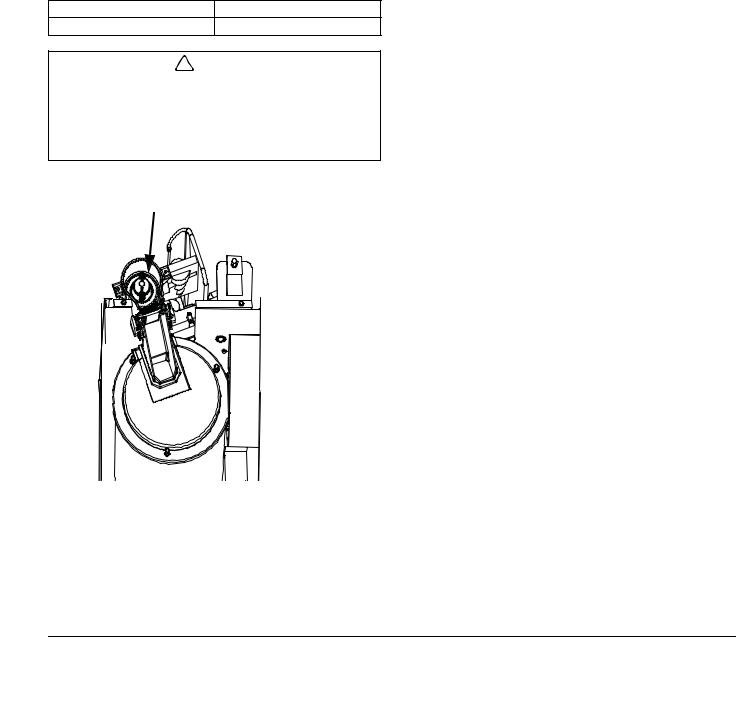
Step 2 Remove the top panel and translucent plastic ice chute cover. Wait about one minute then add the proper amount of Manitowoc Ice Machine Cleaner. Rinse the cleaner from the top of the evaporator with 2 ounces (60 ml) of clear water and re-install cover.
Model |
Amount of Cleaner |
RNS12 RNS20 |
2 ounce (60 ml) |
! Caution
Use only Manitowoc approved Ice Machine Cleaner. It is a violation of Federal law to use these solutions in a manner inconsistent with their labeling. Read and understand all labels printed on bottles before use.
Add Cleaner To Evaporator Here
Step 3 The ice machine will run a wash cycle, a series of rinse cycles and then stop. This entire cycle lasts approximately 30 minutes.
NOTE: Periodic cleaning must be performed on adjacent surface areas not contacted by the water distribution system.
NOTE: The ice machine may be set to start and finish a cleaning procedure, and then automatically start ice making again.
A.After cleaner is added move the switch from CLEAN to ICE position.
B.When the cleaning cycle is complete ice making will start automatically.
Changing toggle switch position during clean cycle:
1.Less than 60 seconds into Clean cycle - The Clean cycle will end when the toggle switch is moved to the OFF position.
2.More than 60 seconds into Clean cycle - The ice machine will complete the Clean cycle. Toggle switch position will determine the next cycle after the Clean cycle is completed.
•CLEAN POSITION - The ice machine will wait for a change in toggle switch position.
•OFF POSITION - The ice machine will wait for a change in toggle switch position.
•ICE POSITION - The ice machine will start making ice automatically.
Manitowoc recommends disassembling, cleaning and sanitizing the ice machine and dispenser every six months.
12 |
Part Number 000008276 10/13 |

Section 4 |
Maintenance |
|
|
PROCEDURE TO CLEAN HEAVILY SCALED FLAKE/ NUGGET ICE MACHINES
Ice machines that are heavily scaled or have not been cleaned on a regular basis will need to run this procedure. Failure to do so may result in binding of the auger as the lime scale releases from the auger and evaporator barrel.
Step 1 Remove panels and set the ICE/OFF/CLEAN toggle switch to the OFF position.
Step 2 Remove all ice from the bin.
Step 3 Turn off the water supply to the ice machine.
Step 4 Place ICE/OFF/CLEAN toggle switch in the CLEAN position. The dump valve will open and drain the water from the evaporator and reservoir.
Step 5 Wait approximately 30 seconds (or until the evaporator is drained) and place the toggle switch in the OFF position.
Step 6 Refer to chart and add the correct amount of cleaner for your model ice machine.
Model |
Amount of Cleaner |
RNS12 RNS20 |
12 ounce (355 ml) |
Step 7 Turn on the water supply to the ice machine.
Important
Leave the cleaner/water solution in the evaporator for a minimum of 4 hours.
Step 8 Move the toggle switch to the ICE position. The compressor will energize and produce ice with the cleaning solution. Continue the freeze cycle for 15 minutes.
Step 9 Move the toggle switch to the OFF position, then follow the standard cleaning (Page 13) and sanitizing procedures (Page 14).
CLEANING PROCEDURE
Ice machines that are heavily scaled or have not been cleaned on a regular basis will need to run the Heavily Scaled Cleaning Procedure before this one. Failure to do so may result in binding of the auger as the lime scale releases from the auger and evaporator barrel.
Ice machine cleaner is used to remove lime scale or other mineral deposits. It is not used to remove algae or slime. Refer to the “Sanitizing Procedure” for removal of algae and slime.
Step 1 Remove panels and set the ICE/OFF/CLEAN toggle switch to the OFF position.
Step 2 Turn off the water supply to the ice machine.
Step 3 Remove all ice from the bin.
Step 4 Place ICE/OFF/CLEAN toggle switch in the CLEAN position. The dump valve will open and drain the water from the evaporator and reservoir.
Step 5 Wait approximately 30 seconds (or until the evaporator is drained) and place the toggle switch in the OFF position.
Step 6 Refer to chart and premix the correct solution of cleaner and cool water for your ice machine.
|
Amount of |
|
|
Model |
Cleaner |
Amount of Water |
|
Part Number |
|||
|
|
||
|
000000084 |
|
|
RNS12 RNS20 |
2 ounces (60 ml) |
32 ounces (1 liter) |
Part Number 000008276 10/13 |
13 |

Maintenance |
Section 4 |
|
|
Step 7 Remove the top cover from the ice chute and pour the cleaner/water solution into the evaporator. Add the entire amount of premixed solution (excess solution will exit through the overflow tube in the water reservoir).
Step 8 Replace the ice chute cover and allow the ice machine to stand for 30 minutes.
Step 9 Turn on the water supply to the ice machine.
Step 10 Move the toggle switch to the ICE position. After the 15 minute delay period expires the compressor will energize and produce ice with the cleaning solution.
Step 11 The ice machine will freeze and discharge the cleaning solution into the bin. Allow the cycle to run for 15 minutes.
Step 12 Place the toggle switch in the OFF position and refer to sanitizing procedure.
NOTE: Discard all ice produced during the cleaning process. Cleaning and sanitizing must be performed on adjacent surface areas not contacted by the water distribution system. Refer to Component Disassembly for Cleaning/Sanitizing (Page 15) - Disassemble, clean and sanitize the ice machine a minimum of once every six months.
SANITIZING PROCEDURE
Ice machine sanitizer is used to remove algae or slime. It is not used to remove lime scale or other mineral deposits. Refer to the “Cleaning Procedure” for removal of lime scale or other mineral deposits.
NOTE: Sanitizing must be performed on adjacent surface areas not contacted by the water distribution system. Always perform Component Disassembly for Cleaning/Sanitizing procedure and a Cleaning Procedure before sanitizing the ice machine.
Step 1 Turn off the water supply to the ice machine.
Step 2 Place ICE/OFF/CLEAN toggle switch in the CLEAN position. The dump valve will open and drain the water from the evaporator and reservoir.
Step 3 Wait approximately 30 seconds (or until the evaporator is drained) and place the toggle switch in the OFF position.
Step 4 Refer to the chart and add the correct amount of sanitizer and cool water for your model ice machine.
Model |
Amount of |
Amount of Water |
|
Sanitizer |
|||
|
|
||
RNS12 RNS20 |
2 ounces (60 ml) |
3 gallons (11 liters) |
Step 5 Remove the top cover from the ice chute and pour the sanitizer/water solution into the evaporator. Add the entire amount of premixed solution (excess solution will exit through the overflow tube in the water reservoir).
Step 6 Replace the ice chute cover and allow the ice machine to stand for 30 minutes.
Step 7 Turn on the water supply to the ice machine.
Step 8 Move the toggle switch to the ICE position. After the 15 minute delay period expires the compressor will energize and produce ice with the sanitizing solution.
Step 9 The ice machine will freeze and discharge the sanitizing solution into the bin. Allow the cycle to run for 15 minutes.
NOTE: Discard all ice produced during the sanitizing process.
Step 10 Place the toggle switch in the CLEAN position. The ice machine will run a wash cycle, a series of rinse cycles and then stop. This entire cycle lasts approximately 30 minutes.
Step 11 Refer to Component Disassembly for Cleaning/Sanitizing, (Page 15) remove clean and sanitize all parts listed.
14 |
Part Number 000008276 10/13 |
Loading...