


 Loading...
 Manitowoc
SM Model
Ice Machines
Installation, Use & Care Manual
This manual is updated as new information and models are released.
Visit our website for the latest manual. www.manitowocice.com
This manual contains English and French text
America’s #1 Selling Ice Machine
Part Number 040001361 05/10

Table of Contents
Section 1 |
|
General Information |
|
Model Numbers . . . . . . . . . . . . . . . . . . . . . . . . . . . . . . . . . . . . . . . . . . . . . . . . . . . . . |
4 |
How to Read a Model Number . . . . . . . . . . . . . . . . . . . . . . . . . . . . . . . . . . . . . . . . . |
4 |
Accessories . . . . . . . . . . . . . . . . . . . . . . . . . . . . . . . . . . . . . . . . . . . . . . . . . . . . . . . |
4 |
Legs . . . . . . . . . . . . . . . . . . . . . . . . . . . . . . . . . . . . . . . . . . . . . . . . . . . . . . . . . . |
4 |
Drain Pump . . . . . . . . . . . . . . . . . . . . . . . . . . . . . . . . . . . . . . . . . . . . . . . . . . . . |
4 |
Manitowoc Cleaner and Sanitizer . . . . . . . . . . . . . . . . . . . . . . . . . . . . . . . . . . . |
4 |
Arctic Pure Water Filter System . . . . . . . . . . . . . . . . . . . . . . . . . . . . . . . . . . . . . |
4 |
Section 2 |
|
Installation Instructions |
|
Installation Prerequisites . . . . . . . . . . . . . . . . . . . . . . . . . . . . . . . . . . . . . . . . . . . . . |
5 |
General . . . . . . . . . . . . . . . . . . . . . . . . . . . . . . . . . . . . . . . . . . . . . . . . . . . . . . . . . . . |
5 |
Location of Ice Machine . . . . . . . . . . . . . . . . . . . . . . . . . . . . . . . . . . . . . . . . . . . . . . |
5 |
Clearances . . . . . . . . . . . . . . . . . . . . . . . . . . . . . . . . . . . . . . . . . . . . . . . . . . . . |
5 |
Electrical Service . . . . . . . . . . . . . . . . . . . . . . . . . . . . . . . . . . . . . . . . . . . . . . . . . . . |
6 |
General . . . . . . . . . . . . . . . . . . . . . . . . . . . . . . . . . . . . . . . . . . . . . . . . . . . . . . . |
6 |
Voltage . . . . . . . . . . . . . . . . . . . . . . . . . . . . . . . . . . . . . . . . . . . . . . . . . . . . . . . |
6 |
Minimum Circuit Ampacity . . . . . . . . . . . . . . . . . . . . . . . . . . . . . . . . . . . . . . . . . |
6 |
Electrical Requirements . . . . . . . . . . . . . . . . . . . . . . . . . . . . . . . . . . . . . . . . . . . |
6 |
Maximum Breaker Size & Minimum Circuit Amperage Chart . . . . . . . . . . . . . . |
6 |
GFCI Requirements . . . . . . . . . . . . . . . . . . . . . . . . . . . . . . . . . . . . . . . . . . . . . . |
6 |
Water Supply and Drain Requirements . . . . . . . . . . . . . . . . . . . . . . . . . . . . . . . . . |
7 |
Water Supply . . . . . . . . . . . . . . . . . . . . . . . . . . . . . . . . . . . . . . . . . . . . . . . . . . . |
7 |
Water Inlet Lines . . . . . . . . . . . . . . . . . . . . . . . . . . . . . . . . . . . . . . . . . . . . . . . . |
7 |
Drain Connections . . . . . . . . . . . . . . . . . . . . . . . . . . . . . . . . . . . . . . . . . . . . . . . |
7 |
Water Supply and Drain Line Sizing/Connections . . . . . . . . . . . . . . . . . . . . . . . |
7 |
Step-by-Step Installation Procedure . . . . . . . . . . . . . . . . . . . . . . . . . . . . . . . . . . . . |
8 |
Drain Pump Option . . . . . . . . . . . . . . . . . . . . . . . . . . . . . . . . . . . . . . . . . . . . . . . . . . |
9 |
Reversing Door Swing . . . . . . . . . . . . . . . . . . . . . . . . . . . . . . . . . . . . . . . . . . . . . . . |
9 |
Installation Check List . . . . . . . . . . . . . . . . . . . . . . . . . . . . . . . . . . . . . . . . . . . . . . . |
10 |
Before Starting the Ice Machine . . . . . . . . . . . . . . . . . . . . . . . . . . . . . . . . . . . . . . . |
10 |
Section 3 |
|
Operation |
|
Sequence of Operation . . . . . . . . . . . . . . . . . . . . . . . . . . . . . . . . . . . . . . . . . . . . . . |
11 |
Control Panel . . . . . . . . . . . . . . . . . . . . . . . . . . . . . . . . . . . . . . . . . . . . . . . . . . . . . . |
11 |
Functions . . . . . . . . . . . . . . . . . . . . . . . . . . . . . . . . . . . . . . . . . . . . . . . . . . . . . . |
11 |
Safety Timers . . . . . . . . . . . . . . . . . . . . . . . . . . . . . . . . . . . . . . . . . . . . . . . . . . . |
12 |
Operational Checks . . . . . . . . . . . . . . . . . . . . . . . . . . . . . . . . . . . . . . . . . . . . . . . . . |
12 |
General . . . . . . . . . . . . . . . . . . . . . . . . . . . . . . . . . . . . . . . . . . . . . . . . . . . . . . . |
12 |
Water Level . . . . . . . . . . . . . . . . . . . . . . . . . . . . . . . . . . . . . . . . . . . . . . . . . . . . |
12 |
Bin Thermostat Adjustment . . . . . . . . . . . . . . . . . . . . . . . . . . . . . . . . . . . . . . . . |
12 |
Testing and Adjusting the Bin Thermostat . . . . . . . . . . . . . . . . . . . . . . . . . . . . . |
13 |
Cube Weight Adjustment . . . . . . . . . . . . . . . . . . . . . . . . . . . . . . . . . . . . . . . . . . |
13 |
2 |
Part Number 040001361 05/10 |

Table of Contents (continued)
Section 4
Maintenance
General . . . . . . . . . . . . . . . . . . . . . . . . . . . . . . . . . . . . . . . . . . . . . . . . . . . . . . . . . . . 14 Interior Cleaning and Sanitizing . . . . . . . . . . . . . . . . . . . . . . . . . . . . . . . . . . . . . . . 15 General . . . . . . . . . . . . . . . . . . . . . . . . . . . . . . . . . . . . . . . . . . . . . . . . . . . . . . . 15 In Place Cleaning/Sanitizing Procedure . . . . . . . . . . . . . . . . . . . . . . . . . . . . . . 15 Cleaning Procedure . . . . . . . . . . . . . . . . . . . . . . . . . . . . . . . . . . . . . . . . . . . . . 16 Removal of Parts For Cleaning/Sanitizing . . . . . . . . . . . . . . . . . . . . . . . . . . . . 17
Exterior Cleaning . . . . . . . . . . . . . . . . . . . . . . . . . . . . . . . . . . . . . . . . . . . . . . . . . . . 21 Cleaning the Condenser . . . . . . . . . . . . . . . . . . . . . . . . . . . . . . . . . . . . . . . . . . . . . 21 General . . . . . . . . . . . . . . . . . . . . . . . . . . . . . . . . . . . . . . . . . . . . . . . . . . . . . . . 21 Removal from Service/Long Term Storage/Winterization . . . . . . . . . . . . . . . . . . 21
General . . . . . . . . . . . . . . . . . . . . . . . . . . . . . . . . . . . . . . . . . . . . . . . . . . . . . . . 21
Self-Contained Air-Cooled Ice Machines . . . . . . . . . . . . . . . . . . . . . . . . . . . . . 21
Section 5
Customer Support
Checklist . . . . . . . . . . . . . . . . . . . . . . . . . . . . . . . . . . . . . . . . . . . . . . . . . . . . . . . . . . 22
Commercial Ice Machine Warranty . . . . . . . . . . . . . . . . . . . . . . . . . . . . . . . . . . . . 23
Residential Ice Machine Limited Warranty . . . . . . . . . . . . . . . . . . . . . . . . . . . . . . 24
Part Number 040001361 05/10 |
3 |

Section 1
General Information
Model Numbers
This manual covers the following models:
Self-Contained
Air-Cooled
SMS050A
! Warning
PERSONAL INJURY POTENTIAL
Do not operate equipment that has been misused, abused, neglected, damaged, or altered/modified from that of original manufactured specifications.
How to Read a Model Number
CONDENSER TYPE
CONDENSER TYPE
A SELF-CONTAINED AIR-COOLED
A SELF-CONTAINED AIR-COOLED
SM S 050 A
|
|
|
ICE MACHINE |
|
|
|
ICE MACHINE |
|
ICE MACHINE |
|
|
MODELDEL |
|
ICE MACHINE |
|
SESERIESI |
|
ICE CUBE SIZE |
|
|
|
||
ICE CUBE SIZE |
|
|
S STANDARD |
|
|
S STANDARD |
|
|
Accessories
Contact your Manitowoc distributor for these optional accessories:
LEGS
Four inch adjustable legs are available.
DRAIN PUMP
Pumps waste water from ice machine to drain.
MANITOWOC CLEANER AND SANITIZER
Manitowoc Ice Machine Cleaner and Sanitizer are available in convenient 16 oz. (473 ml) bottles. These are the only cleaner and sanitizer approved for use with Manitowoc products.
Cleaner Part Number |
Sanitizer Part Number |
16 ounce bottle - 000000084 |
16 ounce bottle - 94-0565-3 |
ARCTIC PURE WATER FILTER SYSTEM
Engineered specifically for Manitowoc ice machines, This water filter is an efficient, dependable, and affordable method of inhibiting scale formation, filtering sediment, and removing chlorine taste and odor. The water filter is K00374.
4 |
Part Number 040001361 05/10 |

Section 2
Installation Instructions
Installation Prerequisites
•Must have open site (gravity) drain available or purchase optional drain pump (see Water Supply and Drain Requirements).
•Must have a grounded, polarized electrical power supply on a dedicated electrical circuit (only appliance on circuit). If GFCI (ground fault circuit interrupter) is required by your local electrical code, it must be breaker type, not outlet type (see Electrical Service).
•Must have cold water supply line available at Ice Machine (see Water Supply and Drain Requirements).
•Clearance and air temperatures must be met (see Location of Ice Machine).
•If built into a cabinet, ice machine must be removable for yearly cleaning procedure.
General
Call Manitowoc Foodservice at (800) 235-9698 for the name of a local company capable of installation and start-up services.
Location of Ice Machine
The location selected for the ice machine must meet the following criteria. If any of these criteria are not met, select another location.
•The ice machine may be built into a cabinet, however the location must allow removal of the ice machine for cleaning and servicing. Service diagnostics are performed from the top of the ice machine.
•The location must be free of airborne and other contaminants.
•The air temperature must be at least 50°F (10°C), but must not exceed 110°F (43°C).
•The location must not be near heat-generating equipment.
•The location must not obstruct air flow through the condenser (airflow is in and out the front of the ice machine).
•The location must allow enough clearance for water, drain and electrical connections at the rear of the ice machine.
•The ice machine may be installed outside.
! Warning
Proper installation requires connection to the water supply, a drain and a dedicated electrical circuit. These connections are the responsibilities of the owner/operator. Improper connections can result in personal injury, substantial property damage and erratic machine operation. If you are unsure of your ability to safely connect the ice machine, consult qualified professionals or contact Manitowoc Foodservice.
Important
Failure to follow these installation guidelines may affect warranty coverage.
! Caution
The ice machine must be protected if it will be subjected to ambient temperatures below 32°F (0°C). Component failure caused by exposure to freezing temperatures is not covered by the warranty.
CLEARANCES
Top/Sides |
5" (12.7 cm)* |
Back |
5" (12.7 cm) |
Front |
24" (60.9 cm) |
*The ice machine may be built into a cabinet. There is no minimum clearance requirement for the top or sides of the ice machine. The listed values are recommended for efficient operation and servicing only.
Part Number 040001361 05/10 |
5 |
Installation Instructions |
Section 2 |
|
|
Electrical Service
GENERAL
! Warning
All wiring must conform to local, state and national codes.
Prepare electrical circuit before installation of your ice machine. Installation requires a grounded (three-prong), polarized receptacle with a separate fuse/circuit breaker in an electrical service box.
VOLTAGE
The maximum allowable voltage variation is ±10% of the rated voltage at ice machine start-up (when the electrical load is highest).
! Warning
The ice machine must be grounded in accordance with national and local electrical codes.
All electrical work, including wire routing and grounding, must conform to local, state and national electrical codes. The following precautions must be observed:
•The ice machine must be grounded.
•A separate fuse/circuit breaker must be provided for each ice machine.
•The maximum allowable voltage variation is +/-10% of the rated voltage at ice machine start-up (when the electrical load is highest).
•Check all green ground screws in the control box and verify they are tight before starting the ice machine.
•Manitowoc’s recommended minimum wire size is #14 for less than 100' (30.5 m) or #12 for more than 100' to 200' (30.5 to 61 m) (solid copper conductor only). The recommended breaker is 15 amp. Local or state electrical code, length of run or materials used, can increase the minimum wire gauge required. A qualified electrician must determine the proper wire size, although #14 is the minimum size allowed.
Important
Observe correct polarity of incoming line voltage.
Incorrect polarity can lead to erratic ice machine operation and a safety issue.
MINIMUM CIRCUIT AMPACITY
The minimum circuit ampacity is used to help select the wire size of the electrical supply. (Minimum circuit ampacity is not the ice machine’s running amp load.)
ELECTRICAL REQUIREMENTS
Refer to Ice Machine Model/Serial Plate for voltage/ amperage specifications.
MAXIMUM BREAKER SIZE & MINIMUM CIRCUIT AMPERAGE CHART
|
Voltage |
Air-Cooled |
||
|
Maximum |
Minimum |
||
Model |
Phase |
Fuse/ |
||
Circuit |
||||
|
Cycle |
Circuit |
||
|
Amps |
|||
|
|
Breaker |
||
|
|
|
||
SM50A |
115/1/60 |
15 |
4.1 |
|
GFCI REQUIREMENTS
If GFCI (ground fault circuit interrupter) is required by local electrical code, it must be breaker type.
6 |
Part Number 040001361 05/10 |
Section 2 |
Installation Instructions |
|
|
Water Supply and Drain Requirements
WATER SUPPLY
Prepare water supply line and drain before installation of your ice machine. Installation requires a 1/4" ID copper cold water line and compression fitting (not supplied).
The ice machine is supplied with a drain hose for gravity draining. The optional drain pump must be purchased if a gravity drain is not possible. Both drain methods require routing to an open site drain. Do not connect directly to drain line as bacteria from drain line may contaminate the ice machine.
The included water filter is designed to inhibit scale formation, filter sediment, and remove chlorine odor and taste. The life expectancy of the water filter is 6 months during normal usage. The ice machine control board will monitor water usage and indicate when replacement is required.
WATER INLET LINES
Follow these guidelines to install water inlet lines:
•Do not connect the ice machine to a hot water supply. Be sure all hot water restrictors installed for other equipment are working. (Check valves on sink faucets, dishwashers, etc.)
•If water pressure exceeds the maximum recommended pressure (80 psi/552 kPA), obtain a water pressure regulator from your Manitowoc distributor.
•Install a water shut-off valve for the ice making water lines.
•Insulate the water inlet line to prevent condensation.
DRAIN CONNECTIONS
Follow these guidelines when installing drain lines to prevent drain water from flowing back into the ice machine and storage bin:
•Drain lines must have a 1.5 inch drop per 5 feet of run (2.5 cm per meter), and must not create traps.
•The floor drain must be large enough to accommodate drainage from all drains.
•Drain pump discharge line must terminate at an open site drain.
•Maximum rise - 12 feet (3.7 m)
•Maximum run - 100 feet (30.5 m)
Approx. Height of Ice Machine Drain
Standard Installation |
3" (76 mm) |
|
|
Installation with Leg Option |
7" (179 mm) |
|
|
WATER SUPPLY AND DRAIN LINE SIZING/CONNECTIONS
! Caution
Plumbing must conform to state and local codes.
Location |
Water Temperature |
Water Pressure |
Ice Machine Fitting |
Tubing Size Up to Ice Machine Fitting |
Ice Making |
35°F (1.6°C) Min. |
20 psi (137.9 kPA) Min. |
1/4" (.64 cm) |
1/4" (.64 cm) minimum inside diameter |
Water Inlet |
90°F (32.2°C) Max. |
80 psi (551.5 kPA) Max. |
ID Copper Tubing |
|
Ice Making |
--- |
--- |
3/4" (1.9 cm) |
3/4" (1.9 cm) minimum inside diameter |
Bin Drain |
Hose Barb |
|
||
|
|
|
||
Drain Pump |
--- |
--- |
3/8" (.96 cm) Hose |
3/8" (.96 cm) ID minimum |
NOTE: If air temperature is less than 60°F (15.5°C), water temperature must be equal to or greater than 50°F (10°C).
Part Number 040001361 05/10 |
7 |
Installation Instructions |
Section 2 |
|
|
Step-by-Step Installation Procedure
1.Prepare the site by following the instructions under Electrical Service and Water Supply and Drain Requirements.
2.Remove ice machine from carton.
3.Inspect for damage.
4.Remove literature/warranty packet and drain hose from inside the ice machine.
5.Adjust leg levelers (or install optional legs).
6.Reverse door if desired. See Reversing Door Swing on page 9.
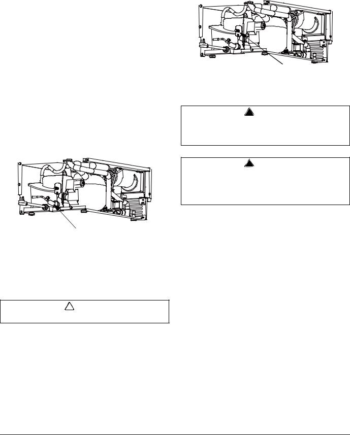
7.For a gravity drain, install drain hose to drain on back of ice machine and route to open site drain. For optional drain pump method, see Drain Pump Option on page 9. Refer to Water Supply and Drain Requirements on page 7.
Drain
10.Connect electrical plug to grounded (three-prong), polarized outlet. See Electrical Service on page 6.
! Warning
The ice machine must be grounded in accordance with national and local electrical codes. Do not use an extension cord or adapter.
Water Inlet
8.Use compression fitting to connect the Water Inlet on back of ice machine to the prepared 1/4" ID cold water line. Refer to Water Supply and Drain Requirements on page 7.
9.Open the shut-off valve on the water line.
! Caution
Check all visible connections for water leakage.
! Warning
Improper water supply and drain connections can result in personal injury and substantial property damage. These connections are the responsibility of the owner/operator.
11.Place ice machine back in position and check leveling again. Make any necessary adjustments.
12.Prepare sanitizer solution and sanitize the ice machine according to In Place Cleaning/Sanitizing Procedure steps 5 and 6.
13.Put one gallon of cold water into a container that will easily pour under the lifted water shutters. Open shutters and add one gallon of cold water.
14.Press Power button.
15.At initial start-up, ice machine will need approximately 30 minutes to freeze ice and up to 5 minutes to harvest the ice.
8 |
Part Number 040001361 05/10 |
Section 2 |
Installation Instructions |
|
|
Drain Pump Option
! Warning
Disconnect power to ice machine before proceeding.
1.Remove top cover screws and slide cover off. Remove back panel screws and lift panel off.
2.Assemble the outlet tube and vent tube to the drain pump.
3.Plug the drain pump’s wire assembly into the ice machine’s wire assembly. Slide drain pump into cavity.
4.Swap out existing Bin Drain Tube for Bin Drain Tube packaged with drain pump.
5.Route the vent tube and outlet tube.
6.Reassemble ice machine.
NOTE: See instructions packaged with drain pump for details.
! Caution
Upon activation, be sure to check all connections for water leakage.
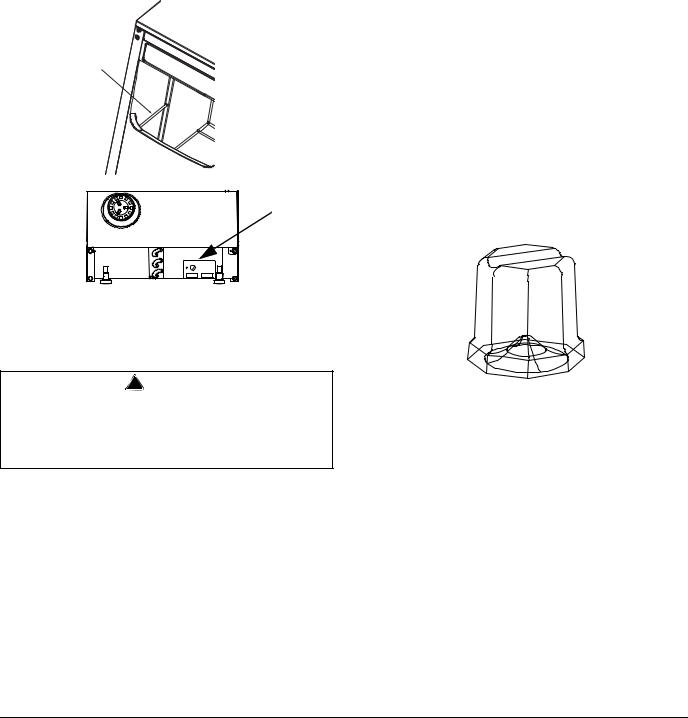
Reversing Door Swing
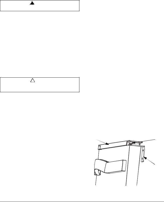
1.Remove top cover from the door - Use a putty knife to lift the inside edge of the top door cover out and up to disengage from the door panel. Repeat on bottom cover.
2.Release door from top hinge - Remove two allen screws from the top of the door and lift door panel off of two bottom allen screws.
NOTE: There are nylon washers for each bottom allen screw and one plastic bushing for the outside screw, do not misplace these parts they help the door swing smoothly.
3.Remove plastic covers from top and bottom hinges and remove screws securing the hinges. Reinstall screws in holes after hinges are removed.
4.Remove existing screws from cabinet to reinstall hinges on opposite side.
5.Install top and bottom hinges in new location.
6.Install the bottom allen screws, nylon washers, and plastic screw cover (to the outside screw).
7.Before installing the door, there is another plastic bushing for the top outside allen screw, remove from top of the door and reinstall on opposite side.
8.Place door on the two bottom screws.
9.Secure top of door with allen screws removed in step 2.
10.Reinstall top and bottom covers on door. Insert front pins first then snap into place.
11.Reverse door handle - Loosen 3 screws from inside door panel until the handle disengages. Flip door handle 180 degrees and tighten screws.
Remove Top |
Remove 2 |
Cover |
Allen Screws |
Remove Plastic
Covers and
Hinges
Part Number 040001361 05/10 |
9 |

Installation Instructions |
Section 2 |
|
|
Installation Check List
Is the Ice Machine level?
Has all of the internal packing been removed?
Have all of the electrical and water connections been made?
Has the supply voltage been tested and checked against the rating on the nameplate?
Is there proper clearance around the ice machine for air circulation?
Is the ice machine grounded and polarity correct?
Has the ice machine been installed where ambient temperatures will remain in the range of 50° - 110°F (10° - 43°C)?
Has the ice machine been installed where the incoming water temperature will remain in the range of 35° - 90°F (2° - 32°C)?
Is the ice machine drain line routed to an open site drain?
Are all electrical leads free from contact with refrigeration lines and moving equipment?
Has the owner/operator been instructed regarding maintenance and the use of Manitowoc Cleaner and Sanitizer?
Has the OWNER WARRANTY REGISTRATION CARD been completed?
Has the ice machine and bin been sanitized?
When installed is the drain pump functioning correctly energizes, de-energizes and safety switch stops the ice machine?
GFCI Required - Is it a breaker type and not a receptacle type?
Is the ice machine plugged into a properly grounded, polarized receptacle?
Have the water and drain connections been examined for leaks?
NOTE: If air temperature is less than 60°F (15.5°C), water temperature must be equal to or greater than 50°F (10°C).
Before Starting the Ice Machine
Sanitize the ice machine.
All Manitowoc ice machines are factory-operated and adjusted before shipment. Normally, new installations do not require any adjustment.
To ensure proper operation, follow the Operational Checks in Section 3 of this manual. Starting the ice machine and completing the Operational Checks are the responsibilities of the owner/operator.
Adjustments and maintenance procedures outlined in this manual are not covered by the warranty.
! Warning
Potential Personal Injury Situation
Do not operate equipment that has been misused. abused, neglected, damaged, or altered/modified from that of original manufactured specifications.
10 |
Part Number 040001361 05/10 |
Section 3
Operation
Sequence of Operation
Depending on ambient conditions and cold water supply temperature, the ice making process will take approximately 30 minutes.
1.Initial Start-Up or Start-Up After Automatic ShutOff — Water Fill
Before the compressor starts, the water inlet valve will energize to purge old water from the system for about 3 minutes.
2.Refrigeration System Start-Up
The compressor starts after the Water Fill cycle and remains on throughout the Freeze and Harvest cycles. The condenser fan motor starts and runs throughout the Freeze cycle.
3.Freeze
The water pump sprays water into the inverted cups. The water freezes layer by layer, until an ice cube forms in each cup. The control system will adjust the length of the Freeze cycle to conditions.
4.Harvest
The water pump shuts off and the water inlet valve starts up to assist harvest and refill the water sump. The evaporator is warmed, allowing the cubes to release from the evaporator and drop into the storage bin. The control system will adjust the length of the Harvest cycle to conditions and regulate whether the condenser fan will run.
At the end of the Harvest cycle, the ice machine will start another Freeze cycle (Step 3).
5.Automatic Shut-Off
The level of ice in the storage bin controls the ice machine shut-off. When the bin is full, ice will contact the bin thermostat bulb holder. The bin thermostat bulb cools, which stops the ice machine. The ice machine remains off until ice no longer contacts the bin thermostat bulb holder and the thermostat bulb warms up. The increase in temperature will restart the ice machine (Step 1).
Control Panel
FUNCTIONS
Power Button (Green)
Pressing the “Power” button once will energize the ice machine and green Power light. Pressing the “Power” button a second time will de-energize the ice machine.
Automatic Ice Making Light (Blue)
This light is energized when the ice machine is the ice making position. The light is off when the ice machine is in the clean cycle.
Delay Start
Pressing the “Delay Start” button will initiate a delay cycle. The ice machine will not run until the delay time expires.
•Pressing the button once will energize the 2 hour light and initiate a two hour delay period.
•Pressing the button a second time will energize the 4 hour light and initiate a four hour delay period.
•Pressing the button a third time will energize the 8 hour light and initiate an eight hour delay period.
•Pressing the button a fourth time will cancel the delay cycle.
Clean (Green)
Pressing the “Clean” button will initiate a clean cycle and de-energize the “Automatic Ice Making” light. The clean light will flash during the clean cycle to indicate the proper time to add ice machine cleaner or sanitizer.
Replace Filter (Red)
When the ice machine completes 8000 freeze/harvest cycles the light will energize to indicate the filter needs replacement. Depressing the “Clean” button for 6 seconds will reset the counter and de-energize the light.
Part Number 040001361 05/10 |
11 |

Operation |
Section 3 |
|
|
SAFETY TIMERS
The control board has the following non-adjustable safety timers:
•Initial cycle is 5 minutes longer than subsequent cycles.
•The ice machine is locked into the freeze cycle for 10 minutes (15 minutes initial cycle) before a harvest cycle can be initiated.
•The maximum freeze time is 120 minutes at which time the control board automatically initiates a harvest cycle (step 4).
•The maximum harvest time is 5 minutes at which time the control board automatically start a freeze cycle.
Operational Checks
GENERAL
Manitowoc ice machines are factory-operated and adjusted before shipment. Normally, new installations do not require any adjustment.
To ensure proper operation, always follow the Operational Checks:
•when starting the ice machine for the first time
•after a prolonged out of service period
•after cleaning and sanitizing
NOTE: Routine adjustments and maintenance procedures are not covered by the warranty.
WATER LEVEL
The ice machine maintains the correct water level. The water level is not adjustable.
BIN THERMOSTAT ADJUSTMENT
The bin thermostat stops the ice machine when the bin is full. Turn the thermostat to the left to decrease the level of ice in bin or to the right to increase the level of ice in bin.
12 |
Part Number 040001361 05/10 |
Section 3 |
Operation |
|
|
TESTING AND ADJUSTING THE BIN THERMOSTAT
The bin thermostat stops the ice machine when the bin is full. It is preset for normal ambient temperatures and adjustments are usually not required.
The thermostat is functioning correctly if, when three ice cubes are placed on the thermostat tube for 5 minutes, the ice machine stops. The ice machine should restart 5 minutes after the cubes are removed.
Bin Thermostat
Tube Location
Bin
Thermostat
If the ice machine stops before the bin is full or runs after the bin is full, ambient temperatures are probably high or low and the bin thermostat can be adjusted as follows:
CUBE WEIGHT ADJUSTMENT
The cube weight can be increased from the factory setting by adjusting the finish time.
Additional finishing time check:
1.Press and hold the power button for 5 seconds.
2.Count the flashes on the Automatic Ice Making light. The light will flash once for each additional minute of freeze cycle time.
Adjusting Finishing Time
Adjust in 1 minute increments and allow the ice machine to run several freeze/harvest cycles, then inspect the ice cubes. If a heavier cube weight is desired add another minute of freeze time and repeat the process.
1.Press and hold the power button.
2.Press and release the clean button once for each additional minute of freeze cycle time desired.
3.Five minutes is the maximum additional freeze time that can be added. Pressing the clean button 6 times will reset the finishing time to zero additional minutes.
! Warning
HAZARDOUS MOVING PARTS
Power is supplied to ice machine during this procedure. Avoid contact with the fan blade and the electrical connections.
1.To access the thermostat, remove the two screws attaching the front grill and remove the grill.
2.Turn the thermostat to the left to decrease the level of ice before automatic shut-off. Turn to the right to increase the level of ice before automatic shut-off.
3.Reassemble the plastic panel and grill.
Cube weight increases or decreases depending on the amount of dimple in the cube
Part Number 040001361 05/10 |
13 |

Section 4
Maintenance
General
You are responsible for maintaining the ice machine in accordance with the instructions in this manual. Maintenance procedures are not covered by the warranty.
! Warning
If you do not understand the procedures or the safety precautions that must be followed, call your local Manitowoc service representative to perform the maintenance procedures for you.
We recommend that you perform the following maintenance procedures a minimum of once every six months to ensure reliable, trouble-free operation and maximum ice production.
Maintenance |
Weekly |
Semi |
Annual |
After prolonged |
At Start-up |
|
Annual |
shutdown |
|||||
|
|
|
|
|||
Clean Cabinet |
X |
|
|
X |
X |
|
Exterior |
|
|
||||
|
|
|
|
|
||
Sanitize Ice Bin |
|
X |
|
X |
X |
|
|
|
|
|
|
|
|
Clean |
|
X |
X |
X |
|
|
Evaporator |
|
|
||||
|
|
|
|
|
||
Sanitize |
|
X |
X |
X |
X |
|
Evaporator |
|
|||||
|
|
|
|
|
||
Clean |
|
X |
X |
X |
|
|
Condenser Coil |
|
|
||||
|
|
|
|
|
||
Change the |
|
X |
X |
X |
|
|
Water Filter |
|
|
||||
|
|
|
|
|
||
Check Ice |
X |
|
X |
X |
X |
|
Quality |
|
|||||
|
|
|
|
|
14 |
Part Number 040001361 05/10 |

Section 4 |
Maintenance |
|
|
Interior Cleaning and Sanitizing
GENERAL
Perform an In Place Cleaning/Sanitizing procedure monthly and a Cleaning/Sanitizing procedure every 12 months for efficient operation. If the ice machine
requires more frequent cleaning and sanitizing, consult a qualified service company to test the water quality and recommend appropriate water treatment. An extremely dirty ice machine must be taken apart for cleaning and sanitizing.
! Caution
Damage to the ice machine evaporator caused by incorrect chemical usage is not covered by the warranty. Use Manitowoc Ice Machine Cleaner (part number 000000084) and Sanitizer (part number 94-0565-3) only.
IN PLACE CLEANING/SANITIZING PROCEDURE
This procedure allows monthly in place cleaning of all surfaces that come in contact with the water system. The ice machine requires disassembly and cleaning/ sanitizing a minimum of once every 12 months. The quality of your potable water supply may require more frequent cleaning intervals.
Use ice machine cleaner to remove lime scale or other mineral deposits. Ice machine sanitizer disinfects and removes algae and slime.
NOTE: All ice must be removed from the bin.
! Warning
Follow all labels and warnings on cleaner and sanitizer bottles.
Step 1 Prepare 4 oz (1/2 cup) of undiluted Manitowoc Ice Machine Cleaner (part number 000000084 only) in a container that will fit easily under the lifted water shutters. Refer to page 18 to identify the water shutters.
Model |
Amount of Cleaner |
SM50 |
4 oz. (120 ml) |
Step 2 Press the clean switch. The ice machine will initiate a 2 minute harvest to remove any remaining ice from the evaporator.
Step 3 Remove all ice from the bin.
Step 4 Wait 3 minutes until the Clean light flashes, then add the prepared Manitowoc Cleaner by lifting the water shutters and pouring directly into the spray area.
Step 5 The ice machine will automatically time out a ten minute cleaning cycle, followed by eight rinse cycles, and stop. The Clean light will turn off to indicate the clean cycle is complete. This entire cycle lasts approximately 30 minutes.
Step 6 Prepare 1/2 oz (1 tablespoon) of undiluted Manitowoc Ice Machine Sanitizer (part number 94-0565-3 only) in a container that will fit into the same area.
Model |
Amount of Sanitizer |
SM50 |
1/2 oz. (15 ml) |
Step 7 Press the Clean switch. Wait 3 minutes until the Clean light flashes, then add the prepared Manitowoc Sanitizer by lifting the water shutters and pouring directly into the spray area. The ice machine will automatically time out a ten minute sanitizing cycle, followed by eight rinse cycles, and stop. The Clean light will turn off to indicate the sanitizing cycle is complete. This entire cycle lasts approximately 30 minutes.
NOTE: The ice machine will automatically continue from the previous point before the clean cycle was initiated.
A.If the ice machine was in the ice making cycle, the control board will start ice making again.
B.If the ice machine was in the off cycle, the control board will turn off.
Step 8 Mix a solution of 1/4 oz. (7.4 ml) of sanitizer and 1/2 gallon (1.9 L) of water. Use a spray bottle, sponge or cloth to sanitize the bin. Rinsing is not required.
Part Number 040001361 05/10 |
15 |
Loading...