


IYT1200A
Part Number: 000014141 Rev 05 11/18
Indigo NXT Ice Machines
Installation, Operation and Maintenance Manual
,
Caution
Read this instruction before operating this equipment.
Original Document

Safety Notices
Safety Notices
Read these precautions to prevent
personal injury:
• Read this manual thoroughly before
operating, installing or performing
maintenance on the equipment. Failure
to follow instructions in this manual
can cause property damage, injury or
death.
• Routine adjustments and maintenance
procedures outlined in this manual are
not covered by the warranty.
• Proper installation, care and
maintenance are essential for
maximum performance and trouble-
free operation of your equipment. Visit
our website www.manitowocice.com
for manual updates, translations, or
contact information for service agents
in your area.
• This equipment contains high
voltage electricity and refrigerant
charge. Installation and repairs are
to be performed by properly trained
technicians aware of the dangers of
dealing with high voltage electricity
and refrigerant under pressure. The
technician must also be certified
in proper refrigerant handling and
servicing procedures. All lockout and
tag out procedures must be followed
when working on this equipment.
• This equipment is intended for indoor
use only. Do not install or operate this
equipment in outdoor areas.
Definitions
DANGER
Indicates a hazardous situation that, if not
avoided, will result in death or serious
injury. This applies to the most extreme
situations.
n
Warning
Indicates a hazardous situation that, if not
avoided, could result in death or serious
injury.
,
Caution
Indicates a hazardous situation that, if not
avoided, could result in minor or moderate
injury.
Notice
Indicates information considered
important, but not hazard-related (e.g.
messages relating to property damage).
NOTE: Indicates useful, extra information
about the procedure you are performing.

n
Warning
Follow these precautions to prevent personal injury during installation of this
equipment:
• Installation must comply with all
applicable equipment fire and health
codes with the authority having
jurisdiction.
• To avoid instability the installation area
must be capable of supporting the
combined weight of the equipment and
product. Additionally the equipment
must be level side to side and front to
back.
• Ice machines require a deflector when
installed on an ice storage bin. Prior to
using a non-OEM ice storage system
with this ice machine, contact the
bin manufacturer to assure their ice
deflector is compatible.
• Prior to installing a non-OEM ice storage
system with this ice machine, follow the
manufacturers installation procedures
and verify the location and installation
meets the local/national mechanical
codes and stability requirements.
• Remove all removable panels before
lifting and installing and use appropriate
safety equipment during installation
and servicing. Two or more people are
required to lift or move this appliance to
prevent tipping and/or injury.
• Legs or casters must be installed and
the legs/casters must be screwed in
completely. When casters are installed
the mass of this unit will allow it to move
uncontrolled on an inclined surface.
These units must be tethered/secured
to comply with all applicable codes.
Swivel casters must be mounted on the
front and rigid casters must be mounted
on the rear. Lock the front casters after
installation is complete.
• Connect to a potable water supply only.
• Do not damage the refrigeration circuit
when installing, maintaining or servicing
the unit.
• This equipment contains refrigerant
charge. Installation of the line sets must
be performed by a properly trained and
EPA certified refrigeration technician
aware of the dangers of dealing with
refrigerant charged equipment.

DANGER
Follow these flammable refrigeration system requirements during installation, use or
repair of this equipment.
• Refer to nameplate - Ice machine models
may contain up to 150 grams of R290
(propane) refrigerant. R290 (propane)
is flammable in concentrations of air
between approximately 2.1% and 9.5%
by volume (LEL lower explosion limit and
UEL upper explosion limit). An ignition
source at a temperature higher than
470°C is needed for a combustion to
occur. Refer to nameplate to identify the
type of refrigerant in your equipment.
• To minimize the risk of ignition due to
improper installation, replacement parts
or service procedures, only refrigeration
technicians with flammable refrigerant
training who are aware of the dangers of
dealing with high voltage electricity and
refrigerant under pressure are allowed to
work on this equipment.
• All replacement parts must be like
components obtained from the
equipment manufacturers authorized
replacement part network.
• This equipment must be installed in
accordance with the ASHRAE 15 Safety
Standard for Refrigeration Systems.
• This equipment can not be installed in
corridors or hallways of public buildings
• Installation must comply with all
applicable equipment fire and health
codes with the authority having
jurisdiction.
• All lockout and tag out procedures
must be followed when working on this
equipment.
• This equipment contains high voltage
electricity and refrigerant charge.
Shorting electrical wires to refrigeration
tubing may result in an explosion. All
electrical power must be disconnected
from the system before servicing the
system. Refrigerant leaks, can result in
serious injury or death from explosion,
fire, or contact with refrigerant or
lubricant mists.
• Do not damage the refrigeration circuit
when installing, maintaining or servicing
the unit. Never use sharp objects or
tools to remove ice or frost. Do not use
mechanical devices or other means to
accelerate the defrosting process.

n
Warning
Follow these electrical requirements
during installation of this equipment.
• All field wiring must conform to all
applicable codes of the authority
having jurisdiction. It is the
responsibility of the end user to
provide the disconnect means to satisfy
local codes. Refer to rating plate for
proper voltage.
• This appliance must be grounded.
• This equipment must be positioned so
that the plug is accessible unless other
means for disconnection from the
power supply (e.g., circuit breaker or
disconnect switch) is provided.
• Check all wiring connections, including
factory terminals, before operation.
Connections can become loose during
shipment and installation.
DANGER
Do not operate equipment that has
been misused, abused, neglected,
damaged, or altered/modified from that
of original manufactured specifications.
This appliance is not intended for use by
persons (including children) with reduced
physical, sensory or mental capabilities,
or lack of experience and knowledge,
unless they have been given supervision
concerning use of the appliance by a
person responsible for their safety. Do
not allow children to play with, clean or
maintain this appliance without proper
supervision.
n
Warning
Follow these precautions to prevent
personal injury while operating or
maintaining this equipment:
• Read this manual thoroughly before
operating, installing or performing
maintenance on the equipment. Failure
to follow instructions in this manual
can cause property damage, injury or
death.
• Crush/Pinch Hazard. Keep hands clear
of moving components. Components
can move without warning unless
power is disconnected and all potential
energy is removed.
• Moisture collecting on the floor will
create a slippery surface. Clean up
any water on the floor immediately to
prevent a slip hazard.
• Objects placed or dropped in the bin
can affect human health and safety.
Locate and remove any objects
immediately.
• Never use sharp objects or tools
to remove ice or frost. Do not use
mechanical devices or other means to
accelerate the defrosting process.
• When using cleaning fluids or
chemicals, rubber gloves and eye
protection (and/or face shield) must be
worn.

DANGER
Follow these precautions to prevent personal injury during use and maintenance of this
equipment:
• It is the responsibility of the equipment
owner to perform a Personal Protective
Equipment Hazard Assessment to ensure
adequate protection during maintenance
procedures.
• Do Not Store Or Use Gasoline Or Other
Flammable Vapors Or Liquids In The
Vicinity Of This Or Any Other Appliance.
Never use flammable oil soaked cloths
or combustible cleaning solutions for
cleaning.
• All covers and access panels must be
in place and properly secured when
operating this equipment.
• Risk of fire/shock. All minimum
clearances must be maintained. Do not
obstruct vents or openings.
• Failure to disconnect power at the main
power supply disconnect could result
in serious injury or death. The power
switch DOES NOT disconnect all incoming
power.
• All utility connections and fixtures must
be maintained in accordance with the
authority having jurisdiction.
• Turn off and lockout all utilities (gas,
electric, water) according to approved
practices during maintenance or
servicing.
• Units with two power cords must be
plugged into individual branch circuits.
During movement, cleaning or repair it is
necessary to unplug both power cords.
• Never use a high-pressure water jet for
cleaning on the interior or exterior of
this unit. Do not use power cleaning
equipment, steel wool, scrapers or wire
brushes on stainless steel or painted
surfaces.
• Two or more people are required to
move this equipment to prevent tipping.
• Locking the front casters after
moving is the owner’s and operator’s
responsibility. When casters are installed,
the mass of this unit will allow it to move
uncontrolled on an inclined surface.
These units must be tethered/secured to
comply with all applicable codes.
• The on-site supervisor is responsible for
ensuring that operators are made aware
of the inherent dangers of operating this
equipment.
• Do not operate any appliance with a
damaged cord or plug. All repairs must
be performed by a qualified service
company.

THIS PAGE INTENTIONALLY LEFT BLANK

Table of Contents
Part Number: 000014141 Rev 05 11/18 9
Safety Notices
Safety Notices ...........................................................................3
Section 1
General Information
Model Numbers ......................................................................11
Accessories ..............................................................................11
How To Read A Model Number ................................................ 12
Section 2
Installation
Installation ..............................................................................13
Location Requirements ............................................................ 13
Installation Requirements ........................................................ 13
Ice Machine Heat of Rejection .................................................14
Air Baffle .................................................................................16
Bin Installation Requirements .................................................. 16
Bin Installation ........................................................................17
Dispenser Installation .............................................................. 17
Electrical Requirements ...........................................................18
Maximum Breaker Size & Minimum Circuit Amperage Chart .... 19
Water Supply and Drain Line Sizing/Connections ..................... 22
Water Connections .................................................................. 22
Water Supply and Drain Connections ....................................... 23
Air Gap .................................................................................. 23
Cooling Tower Applications
(Water-Cooled Models) ...........................................................24
Drain Connections ...................................................................24
Remote Condenser and Condensing Unit Refrigeration
System Installation ..................................................................25
Calculating Installation Distances ......................................... 26
Remote Condenser Models .................................................. 27
QuietQube Models ............................................................... 28
Starting the Ice Machine .......................................................... 32
Remove Ice Thickness Probe Shipping Brackets ................... 32
Minimum/Maximum Slab Weight ........................................ 32
Warranty ................................................................................. 32
Warranty Registration ........................................................... 32
Remote Ice Machine Usage with Non-Manitowoc
Multi-Circuit Condensers .........................................................33

10 Part Number: 000014141 Rev 05 11/18
Table of Contents (continued)
Section 3
Operation
Touch Screen Features ............................................................. 35
Home Screen Icon Descriptions ............................................ 36
Setup Wizard ........................................................................... 37
Menu Screen Navigation .......................................................... 38
Ice Making Sequence of Operation ..........................................39
Control Board Timers ............................................................... 39
Minimum/Maximum Slab Weight ............................................ 41
Ice Thickness Check .................................................................41
Reverse Osmosis or Deionized Water Usage ............................42
Section 4
Maintenance
Cleaning and Sanitizing ............................................................ 43
Cleaning/Sanitizing Procedure ................................................. 44
Cleaning Procedure ............................................................... 44
Sanitizing Procedure ............................................................. 45
Parts Removal for Cleaning/Sanitizing ..................................... 46
Preventative Maintenance Cleaning Procedure ........................ 48
Cleaning the Air Filter and Condenser ...................................... 49
Removal from Service/Winterization ....................................... 49
Section 5
Troubleshooting
Before Calling for Service Checklist .......................................... 51
Service Faults ..........................................................................53
Part Number: 000014141 Rev 05 11/18 11
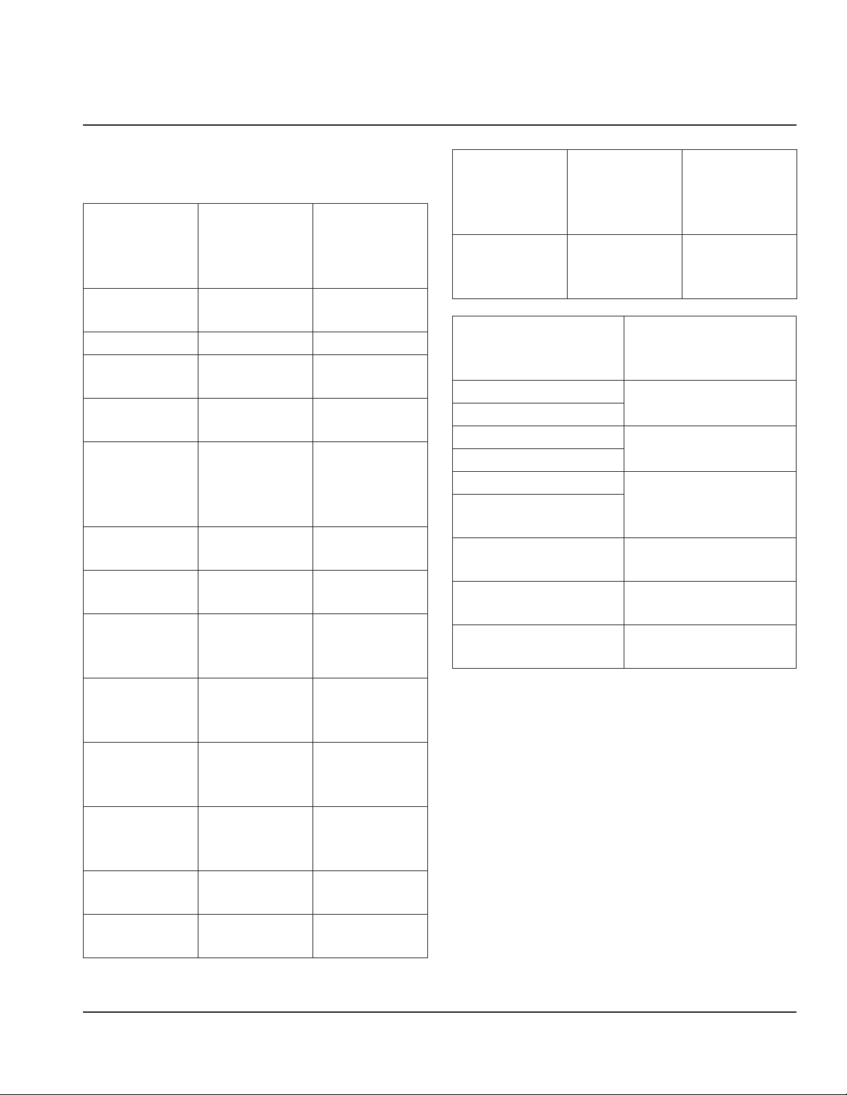
Model Numbers
This manual covers the following models:
Self-
Contained
Air-Cooled
Self-
Contained
Water-
Cooled
Remote Air-
Cooled
IDF0300A
IYF0300A
IDF0300W
IYF0300W
----
----
IYP0320A ---- ----
IDT0420A
IYT0420A
IDT0420W
IYT0420W
----
----
IDT0450A
IYT0450A
IDT0450W
IYT0450W
----
----
IDT0500A
IYT0500A
IRT0500A
IDP0500A
IDT0500W
IYT0500W
IRT0500W
----
IDT0500N
IYT0500N
----
----
IDP0520A
IYP0520A
----
----
----
----
IDF0600A
IYF0600A
IDF0600W
IYF0600W
IDF0600N
IYF0600N
IDT0620A
IYT0620A
IRT0620A
IDT0620W
IYT0620W
----
----
----
----
IDT0750A
IYT0750A
IRT0750A
IDT0750W
IYT0750W
IRT0750W
----
----
----
IDF0900A
IYF0900A
IRF0900A
IDF0900W
IYF0900W
IRF0900W
IDF0900N
IYF0900N
----
IDT0900A
IYT0900A
IRT0900A
IDT0900W
IYT0900W
IRT0900W
----
----
----
IDT1200A
IYT1200A
IDT1200W
IYT1200W
IDT1200N
IYT1200N
IDT1500A
IYT1500A
IDT1500W
IYT1500W
IDT1500N
IYT1500N
Self-
Contained
Air-Cooled
Self-
Contained
Water-
Cooled
Remote Air-
Cooled
IDT1900A
IYT1900A
IRT1900A
IDT1900W
IYT1900W
----
IDT1900N
IYT1900N
IRT1900N
QuietQube
Indoor Head Section
QuietQube
Air-Cooled
Condensing Unit
IYF0600C
CVDF0600
IBF0620C
IBF0820C
CVDF0900
IYF0900C
IBT1020C
CVDT1200
IDT1200C
IYT1200C
IDF1400C
IYF1400C
CVDF1400
IDF1800C
IYF1800C
CVDF1800
IDF2100C
IYF2100C
CVDF2100
Accessories
Ice Deflector
An ice deflector is required when the
ice machine is installed on a bin. An ice
deflector is not required when the ice
machine is installed on a dispenser.
Section 1
General Information

12 Part Number: 000014141 Rev 05 11/18
General Information Section 1
Top Air Discharge Kit
The top air discharge kit can be used on
select ice machine models. This kit directs
warm exhaust air upward rather than out
the side panels.
AuCS® Automatic Cleaning System
This accessory reduces equipment cleaning
expense. The AuCS® accessory monitors
ice making cycles and initiates cleaning
procedures automatically.
LuminIce® II
The LuminIce® growth inhibitor recirculates
the air in the ice machine foodzone over
a UV bulb. This process will inhibit the
growth of common micro-organisms on all
exposed foodzone surfaces.
How To Read A Model Number
I Y T 1500 N — 261 X
Ice Machine Model
I - Indigo Model
IB - Ice Beverage
X - LuminIce
A - Alternate Compressor
HP - High Pressure Water
Regulating Valve
Ice Cube Size
R - Regular
D - Dice
Y - Half-Dice
Not Used On IB Models
P - Correctional Model
M - Marine Model
V - Space Saver
Q - Coated Condenser
Blank - General Usage
Refrigerant
P - R290
F - R404A
T - R410
Voltage
161 - 115/60/1
261 - 208-230/60/1
251 - 230/50/1
263 - 208-230/60/3
463 - 460/60/3
Nominal Production
Condenser Type
A - Self-Contained Air-Cooled
W - Self-Contained Water-Cooled
N - Remote Air-Cooled
C - CVD Air-Cooled
NOTE: These products are hermetically sealed and contain fluorinated greenhouse gas
R404A or R410A.

Part Number: 000014141 Rev 05 11/18 13
Installation
Location Requirements
The location selected for the ice machine
head section must meet the following
criteria. If any of these criteria are not met,
select another location.
• The location must be indoors and
must be free of airborne and other
contaminants.
• The location must not be near heat-
generating equipment or in direct
sunlight.
• The location must allow enough
clearance for water, drain, and electrical
connections in the rear of the ice
machine.
• The location must not obstruct airflow
through or around the ice machine.
Installation Requirements
• The ice machine and bin must be level.
• Vent the ice machine and bin drains
separately.
• Bin drain termination must have an air
gap.
• The ice machine and bin must be
cleaned and sanitized after installation.
• The drain line must contain a union or
other suitable means of disconnection at
the ice machine.
QuietQube Models Only
• The ice machine top panel can be
trimmed with an aviator snips to allow
the line set, water line and electrical
connections to exit the top. Only cut out
what is needed, the back panel must
support the top panel.
• The water inlet and electrical connection
must contain a service loop to allow
future access.
Section 2
Installation
14 Part Number: 000014141 Rev 05 11/18
Installation Section 2
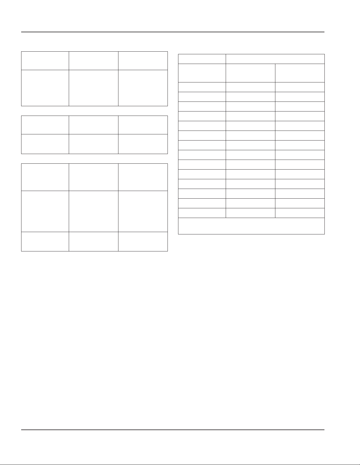
Minimum/Maximum Temperatures
Model
Minimum Air
Temperature
Maximum Air
Temperature
All Ice
Machine
Head
Sections
35°F
2°C
110°F
43°C
Remote
Condensers
Minimum Air
Temperature
Maximum Air
Temperature
All Models
-20°F
-29°C
120°F
49°C
QuietQube
Condensing
Units
Minimum Air
Temperature
Maximum Air
Temperature
CVDF0600
CVDF0900
CVDT1200
CVDF2100
-20°F
-29°C
120°F
49°C
CVDF1400
CVDF1800
-20°F
-29°C
130°F
54°C
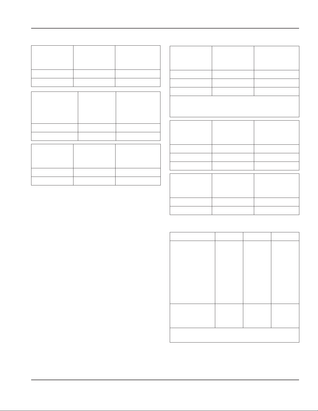
Ice Machine Heat of Rejection
Ice Machine Heat of Rejection
Series
Air
Conditioning
Peak
IF0300 4600 5450
IT0420 3800 6000
IT0450 3800 6000
IT0500 3800 6000
IP0500 3800* 6000*
IP0520 3800* 6000*
IF0600 11800 13700
IT0620 5400 6300
IT0750 11800* 13700*
IF0900 13000 16000
IT0900 13000* 16000*
IT1200 16200 19100
IT1500 23000 27000
IT1900 26100 30500
* Data marked with an asterisk is preliminary
and subject to change
Use this information when:
• Sizing air conditioning equipment where
self-contained air-cooled ice machines
are installed.
• Determining the load on a cooling tower.
Use the peak figure for sizing the load.
Part Number: 000014141 Rev 05 11/18 15
Section 2 Installation
Clearance Requirements
IF0300
Self-
Contained
Air-Cooled
Self-
Contained
Water-Cooled
Top/Sides 16" (40 cm) 8" (20 cm)
Back 5" (13 cm) 5" (13 cm)
IT0420 IT0450
IT0500 IP0500
IP0520 IF0600
IT0620 IT0750
Self-
Contained
Air-Cooled
Water-Cooled
or Remote
Condenser
Top/Sides 12" (31 cm) 8" (20 cm)
Back 5" (13 cm) 5" (13 cm)
IF0900
IT0900
Self-
Contained
Air-Cooled
Self-
Contained
Water-Cooled
Top/Sides 8" (20 cm) 8" (20 cm)
Back 5" (13 cm) 5" (13 cm)
NOTE: Top air discharge kits require the
same clearance requirements as the
comparable self-contained air-cooled
model.
IT1200
Self-
Contained
Air-Cooled
Water-Cooled
or Remote
Condenser
Top 8" (20 cm)* 8" (20 cm)*
Sides 12" (31 cm)* 8" (20 cm)*
Back 5" (13 cm)* 5" (13 cm)*
* Data marked with an asterisk is preliminary
and subject to change - Model/serial plate
information overrides all data listed in this chart.
IT1500
Self-
Contained
Air-Cooled
Water-Cooled
or Remote
Condenser
Top 12" (31 cm) 8" (20 cm)
Sides 8" (20 cm) 8" (20 cm)
Back 12" (31 cm) 5" (13 cm)
IT1900
Self-
Contained
Air-Cooled
Water-Cooled
or Remote
Condenser
Top/Sides 24" (61 cm) 8" (20 cm)
Back 12" (31 cm) 5" (13 cm)
QuietQube Model Clearance Requirements
Model Top Back Sides
IF0600C
IT0750C
IF0900C
IT0900C
IT1200C
IF1400C
IF1800C
IF2100C
5"
(13 cm)
5"
(13 cm)
5"
(13 cm)
IBF0620C
IBF0820C
IBF1020C
2"**
(5 cm)
5"
(13 cm)
8" **
(20 cm)
** 24" (61 cm) is recommended on top/sides for
servicing
16 Part Number: 000014141 Rev 05 11/18
Installation Section 2
Condensing Unit Clearance Requirements
Model
Top/
Sides
Back Front
CVDF0600
CVDF0900
CVDT1200
CVDF1400
CVDF1800
CVDF2100
0"
(0 cm*)
48"
(122 cm)
48"
(122 cm)
* 24" (61 cm) is recommended on top/sides for
servicing
Notice
The ice machine must be protected if it
will be subjected to temperatures below
32°F (0°C). Failure caused by exposure to
freezing temperatures is not covered by
the warranty.
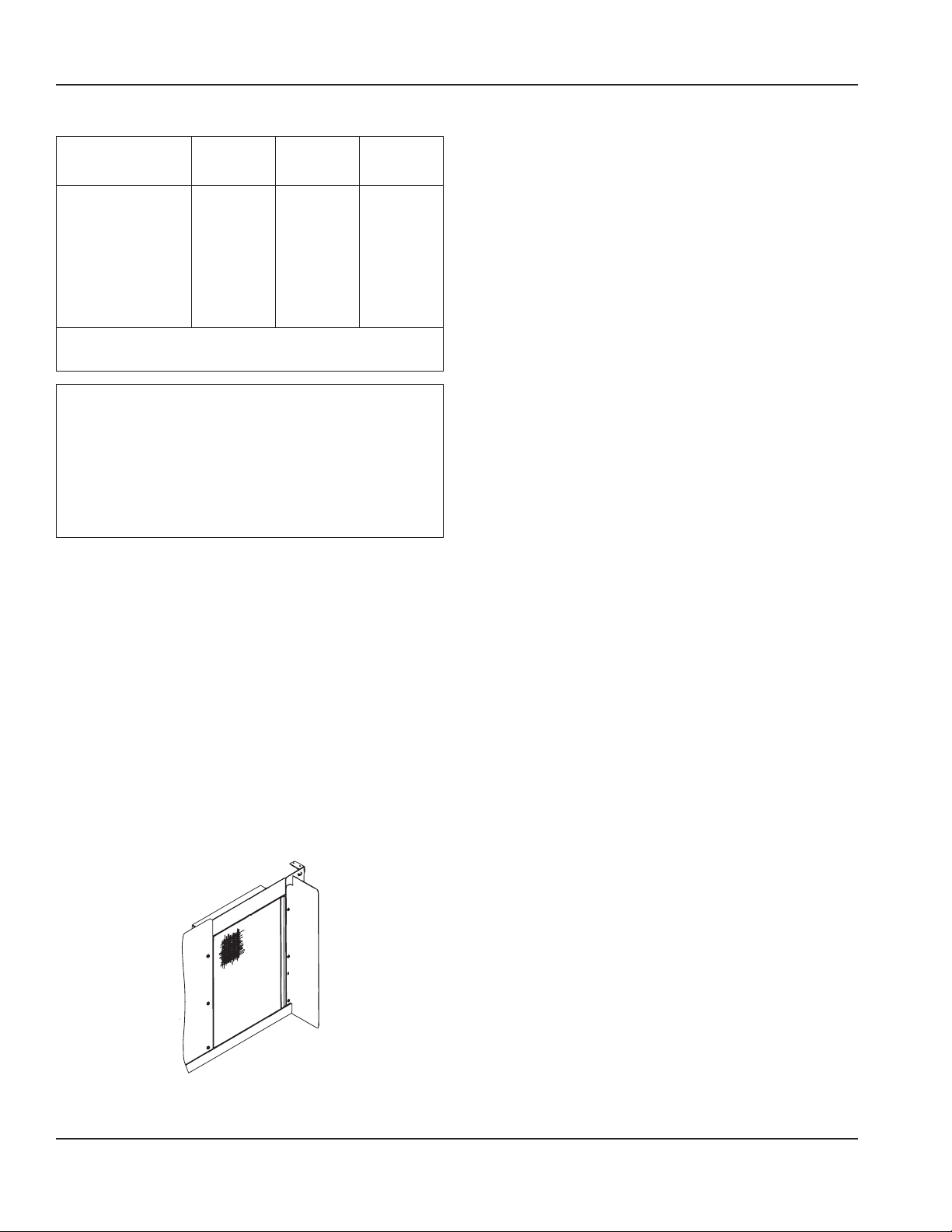
Air Baffle
Self-Contained Air-cooled Only
The air-cooled baffle prevents condenser
air from recirculating.
To install:
1. Loosen the back panel screws next to
the condenser.
2. Align the keyhole slots in the air baffle
with the screw holes and slide the
baffle down to lock in place.
Bin Installation Requirements
• The installation area must be capable of
supporting the combined weight of the
equipment and product.
• All ice machines installed on a bin
require an ice deflector.
• Manitowoc bins have a deflector
installed and require no modifications
when used with a forward-facing
evaporator.
• Ice machines with multiple evaporators
require a deflector kit.
• Align sides and back of ice machine with
sides and back of bin when placing ice
machine on bin.
• Optional sales kits are available to adapt
various sized or multiple ice machines on
large bins.

Part Number: 000014141 Rev 05 11/18 17
Section 2 Installation
Bin Installation
NOTE: When using casters, the units must
be tethered or secured to comply with all
applicable codes. Swivel casters must be
mounted on the front and rigid casters
must be mounted on the rear. Lock the
front casters after installation is complete.
1. Remove threaded plug from drain
fitting.
2. Screw the leveling legs onto the
bottom of the bin.
3. Screw the foot of each leg in as far as
possible.
4. Move the bin into its final position.
5. Level the bin to assure that the bin
door closes and seals properly. Use a
level on top of the bin. Turn the base
of each foot as necessary to level the
bin.
6. Inspect bin gasket prior to ice machine
installation. (Manitowoc bins come
with a closed cell foam gasket installed
along the top surface of the bin.)
7. Remove all panels from ice machine
before lifting and installing on bin.
Remove front panel, top cover, left and
right side panels.
Dispenser Installation
Observe following recommendations unless
required by the dispenser manufacturer.
• An adapter is not required for ice
machines that match the dispenser size.
• A deflector is not required.
• Ice level management is recommended
to prevent water leakage or movement
of ice machine during agitation.
• Align sides and back of ice machine with
sides and back of dispenser when placing
ice machine.
• Follow ice machine installation
procedures in this manual and any
additional installation requirements
specified by the dispenser manufacturer.
 Loading...