

Page 1
MAN GUIDE 107
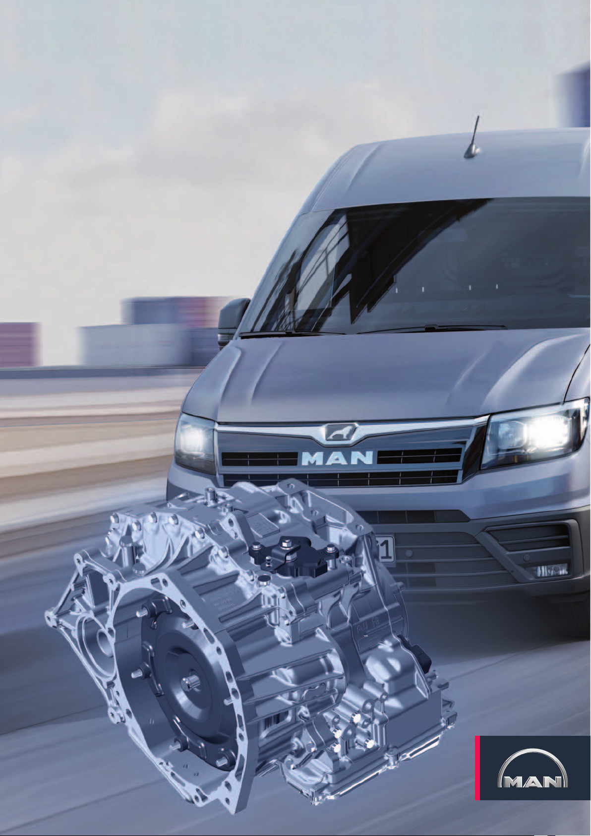
TGE - The 8-speed automatic gearbox
Page 2
The gearbox variants in the TGE
In addition to the 6-speed manual gearbox described in the TGE GUIDE 105, the TGE can also be equipped with an
8-speed automatic gearbox. It is a consistent further development of the well-known 6-speed automatic gearbox from
AISIN AW CO., LTD. of Japan.
Technical status April 2019
2
m107_039
Page 3
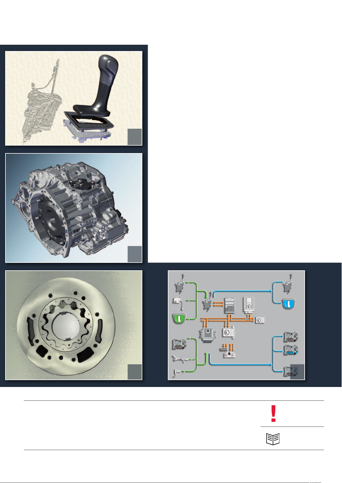
table of contentS
4 IntroductIon
6 Selector lever
10 Gearbox deSIGn
18 valve body
4
20 oIl Supply
22 Gearbox manaGement
34 ServIce
10
20
35 teSt your knowledGe
22
The MAN TGE Guide teaches the basics of design and function for sales and after-sales of new vehicle models, new
vehicle components or new technologies.
The MAN TGE Guide is not a sales manual nor a repair guide! Specified values are for the sake of easy understanding
only and refer to the data status valid at the time the MAN TGE Guide was created.
The contents are not updated.
Please use the appropriate technical literature for customer advice, maintenance and repair work.
Note
Reference
3
Page 4
IntroductIon
The features of the 8-speed automatic gearbox
The new 8-speed automatic gearbox from Aisin is characterised by the following technical features:
Auxiliary hydraulic pump 1 for gearbox oil V475 for assuring the oil supply in start/stop operation
Torque converter with starter ring gear
Two additional electric pressure control valves for gears 7 and 8
An additional clutch on the Lepelletier planetary gearbox for gears 7 and 8
Design of one of the two brakes as a band brake
m107_016
Note
The exact technical design of the 8-speed automatic
gearbox depends on the engine of the respective vehicle
model.
4
Page 5

The technical data for the 8-speed automatic gearbox
Manufacturer
Gearbox code
Gearbox features
Maximum torque
ATF specification for gearbox oil
Filling quantity gear oil
Filling quantity bevel box
AISIN AW CO., LTD. Japan
AQ 450
8-speed automatic gearbox with single Lepelletier planetary gearbox
450Nm
G 055 540 A2
7.65 litres at a change interval of 200,000 km
0.86 litres lifetime filling
The drive train in the TGE
The diverse applications of the TGE mean there are also several variants of power transmission in
its drive concept. The spectrum ranges from front-wheel drive with manual gearbox to four-wheel
drive with 8-speed automatic gearbox including a Generation 5 four-wheel drive coupling and
electronic differential lock.
Power transmission
Gearbox
6-speed manual
gearbox
8-speed automatic
gearbox
This booklet presents the design and function of the 8-speed automatic gearbox with its components for front and
four-wheel drive.
Engine Type of drive Four-wheel drive
coupling
2.0 l TDI with 75 kW Front-wheel
drive
2.0 l TDI with 103 kW Front-wheel
drive and
four-wheel
drive
2.0 l TDI with 130 kW Front-wheel
drive and
four-wheel drive
2.0 l TDI with 103 kW Front-wheel
drive
2.0 l TDI with 130 kW Front-wheel
drive
2.0 l TDI with 130 kW Four-wheel
drive
No No
Generation 5 bevel
box and four-wheel
drive coupling
Generation 5 bevel
box and four-wheel
drive coupling
No No
No No
Generation 5 bevel
box and four-wheel
drive coupling
Differential lock
Electrical differential
lock (optional)
Electrical differential
lock (optional)
Electrical differential
lock (optional)
5
Page 6
Selector lever
The selector lever may differ in appearance from one vehicle to another. The operation and function
are the same for all vehicles with this automatic gearbox.
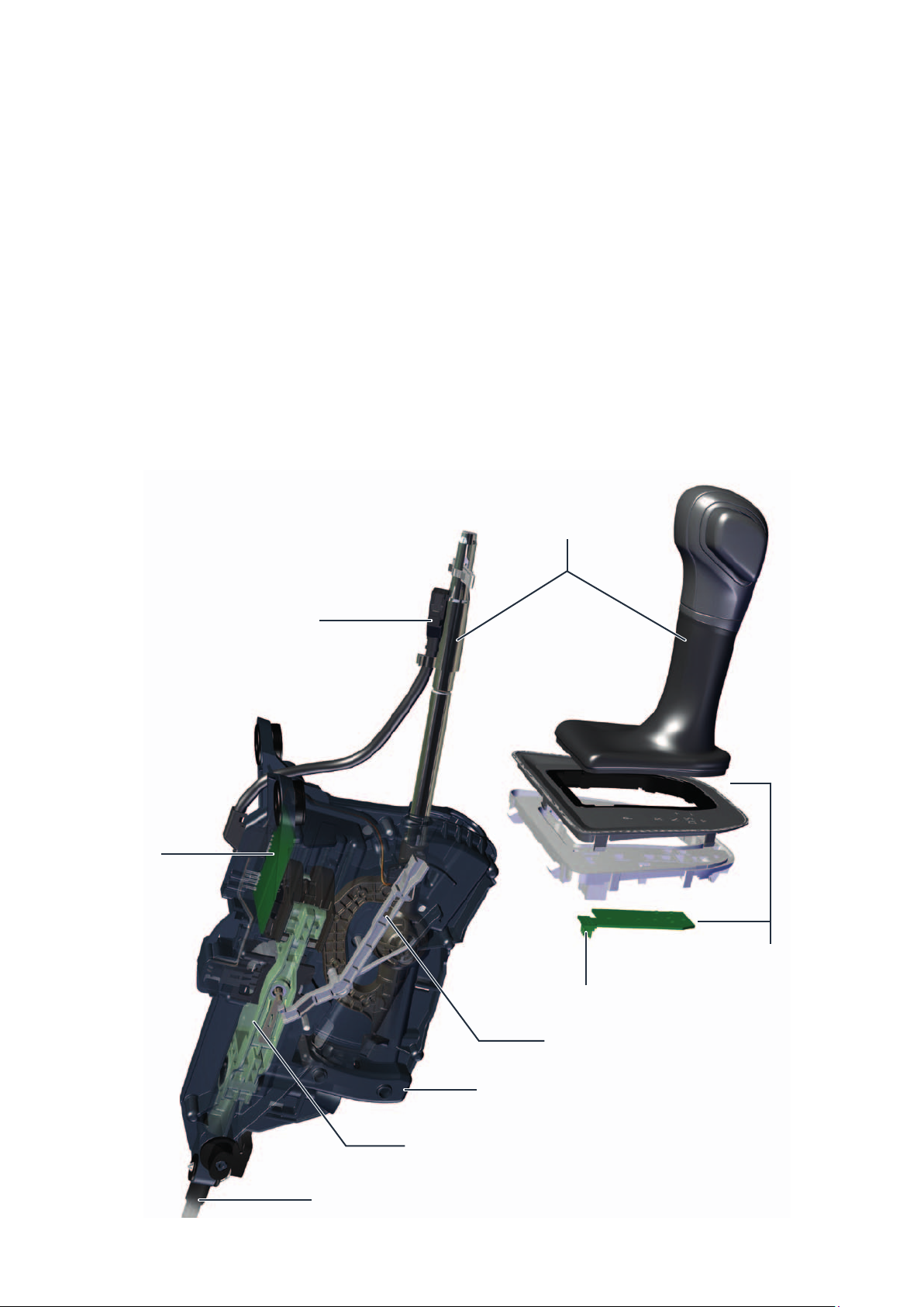
Design of the selector lever module
The selector lever module is made up of the following main components:
The selector mechanism
The selector lever with bellows
The selector lever position display Y6
The selector lever locked in position “P” switch F319
Plug connection C for selector lever
position display Y6
The selector lever lock solenoid N110
The Tiptronic switch F189
Switch for selector lever gate detection F257
Mechanical, manual emergency release
Selector lever
Electronics of
the selector
mechanism
6
Selector lever cable
Selector lever electronics
with switch for Tiptronic F189
Connector A to the vehicle
wiring harness for the gearbox
Emergency release
Selector housing
Selector mechanism
m107_042
Page 7
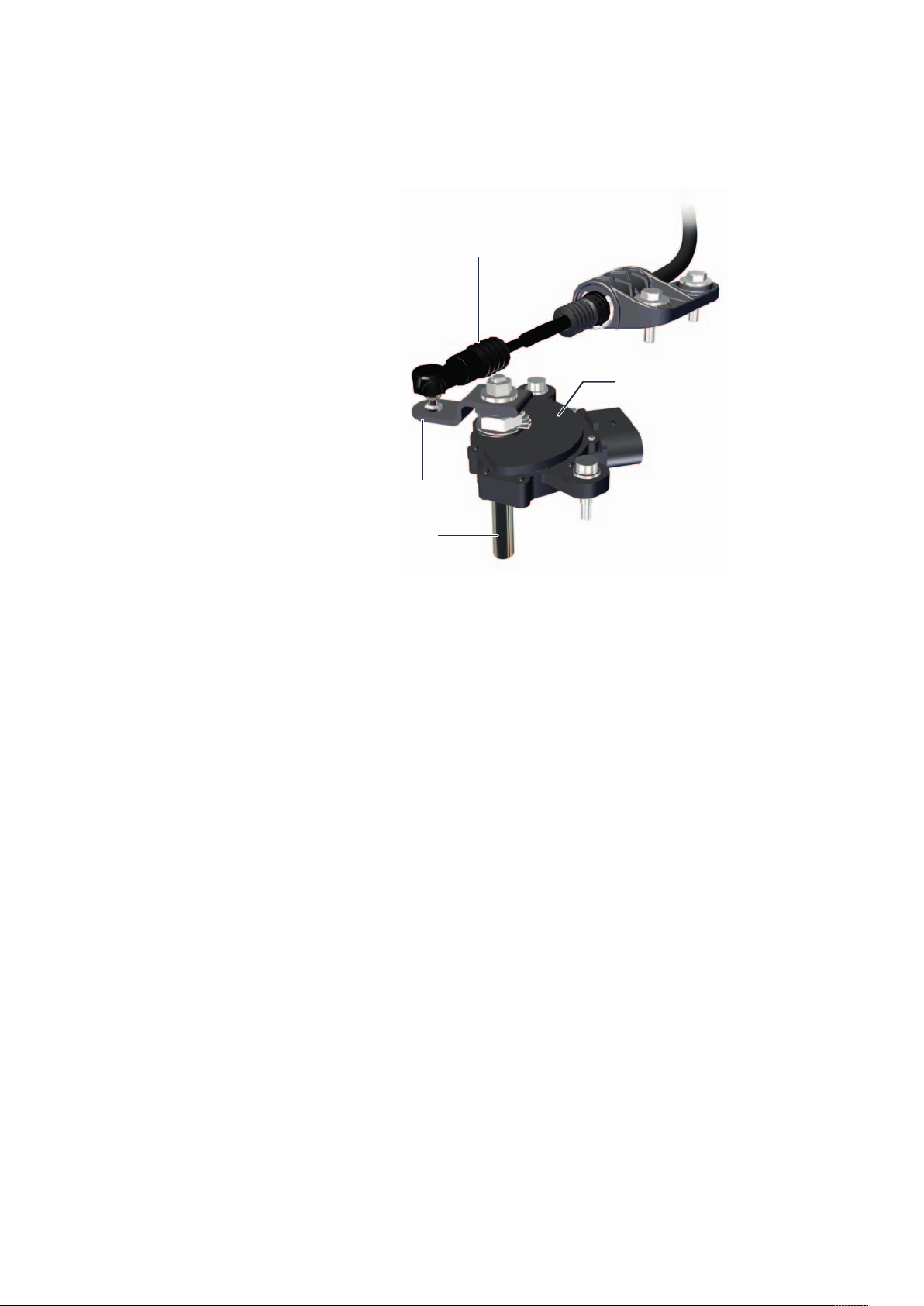
How the selector lever module works
The selector lever operates the selector slide in the
valve body and the multifunction switch via the
selector lever cable and a relay lever. The selector
lever module has both mechanical and electrical
functions.
Relay lever
Selector lever cable
Multifunction switch
Shaft to selector slide
Mechanical functions
Actuation of the parking lock
Actuation of the selector slide of the hydraulic
control unit
Actuation of the multifunction switch in the gearbox
Electrical functions
Ignition key withdrawal lock
Control of the display unit for selector lever position
(via gear control unit)
Tiptronic function
Selector lever lock (P/N lock)
Further electrical elements of the switching operation
Multifunction switch
The multifunction switch is connected to the selector
mechanism via a cable.
In the multifunction switch, the mechanical movement
of the cable is converted into electrical signals according to the selector lever position and transmitted to
the control unit for the automatic gearbox.
Selector lever locked in position “P” switch F319
The switch is operated by the selector lever in the “P”
position. It then sends a signal “selector lever in
position P” to the control unit for steering column
electronics.
The control unit needs this signal to control the ignition
key withdrawal lock.
m107_014
Switch for selector lever gate detection F257
The switch recognises the position of the selector lever
and thus the driver‘s wish. The signal is compared with
that of the multifunction switch and checked for
plausibility.
Tiptronic switch F189
The switch detects the Tiptronic gate as well as “Tip +”
and “Tip -”. The signal is sent via analogue line to the
gearbox control unit.
7
Page 8
Selector lever
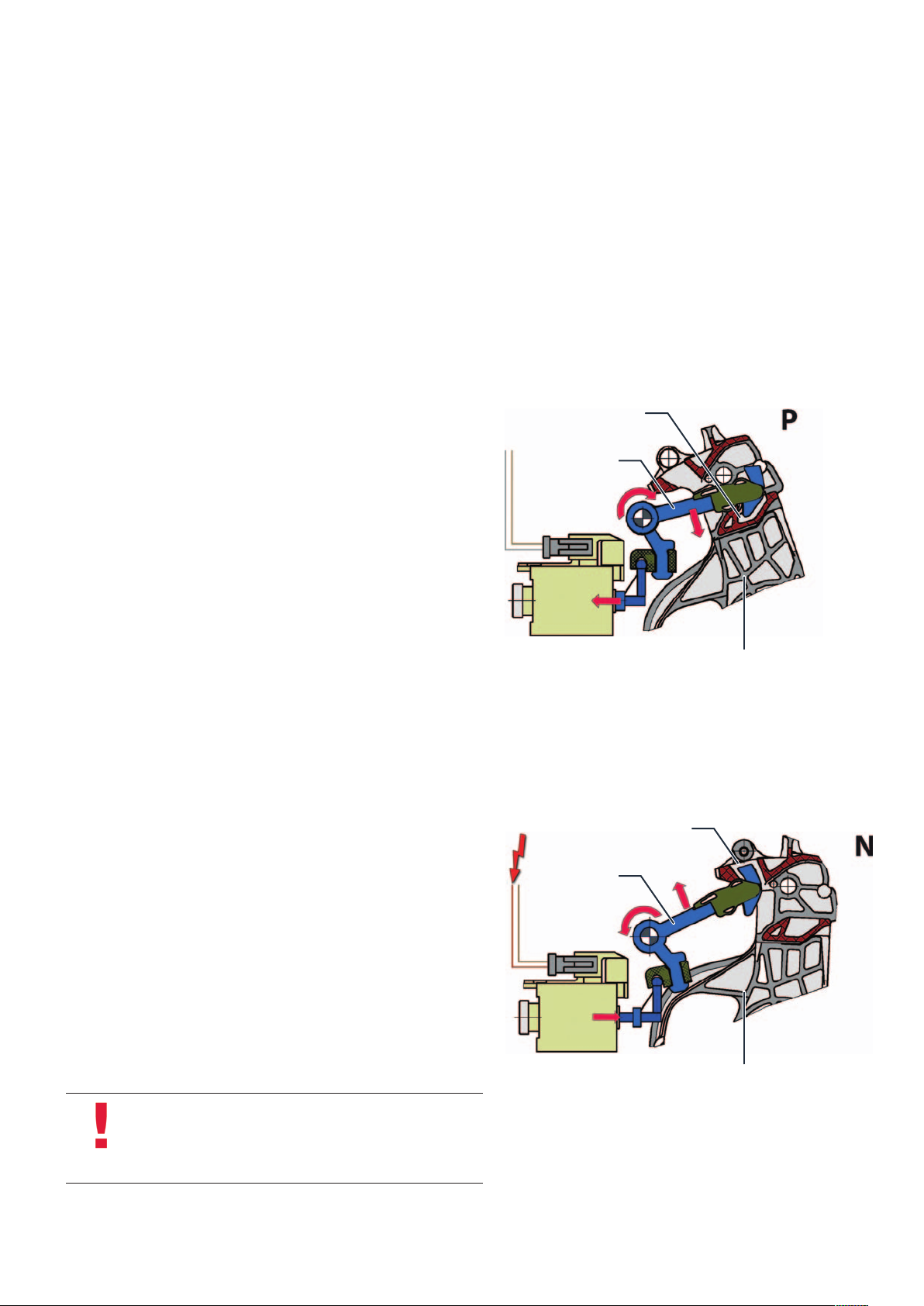
Selector lever lock
The selector lever lock is engaged when the ignition is switched on and in the P and N positions
during vehicle operation. When the ignition key is removed, the lock is engaged in the P position.
The locking mechanism enables the selector lever to be locked both when the selector lever lock
solenoid N110 is deenergised (position P) and when the solenoid is energised (position N).
Lock in selector lever position P
If the solenoid N110 is deenergised, the locking lever automatically
engages in the P latch in the selector mechanism as soon as the
selector lever is brought into position P. This movement of the locking
lever is supported by a spring in the solenoid N110.
For unlocking, the solenoid N110 is energised, which means the
solenoid pulls the locking lever out of the P latch.
Lock in selector lever position N
Solenoid N110 is activated if the selector lever is in position N. The
solenoid then pushes the locking lever with its upper hook into the N
latch and the selector lever locks. The solenoid N110 is switched off
to release. The weight of the locking lever causes it to drop down and
release the selector lever again.
Locking lever
Selector lever
lock solenoid
N110
Locking lever
P latch
Selector mechanism
m107_025
N latch
Selector lever
lock solenoid
N110
Note
In the event of a defect or a power failure, the selector
lever remains locked. In this case, a locked selector lever
can be unlocked mechanically.
8
Selector mechanism
m107_026
Page 9
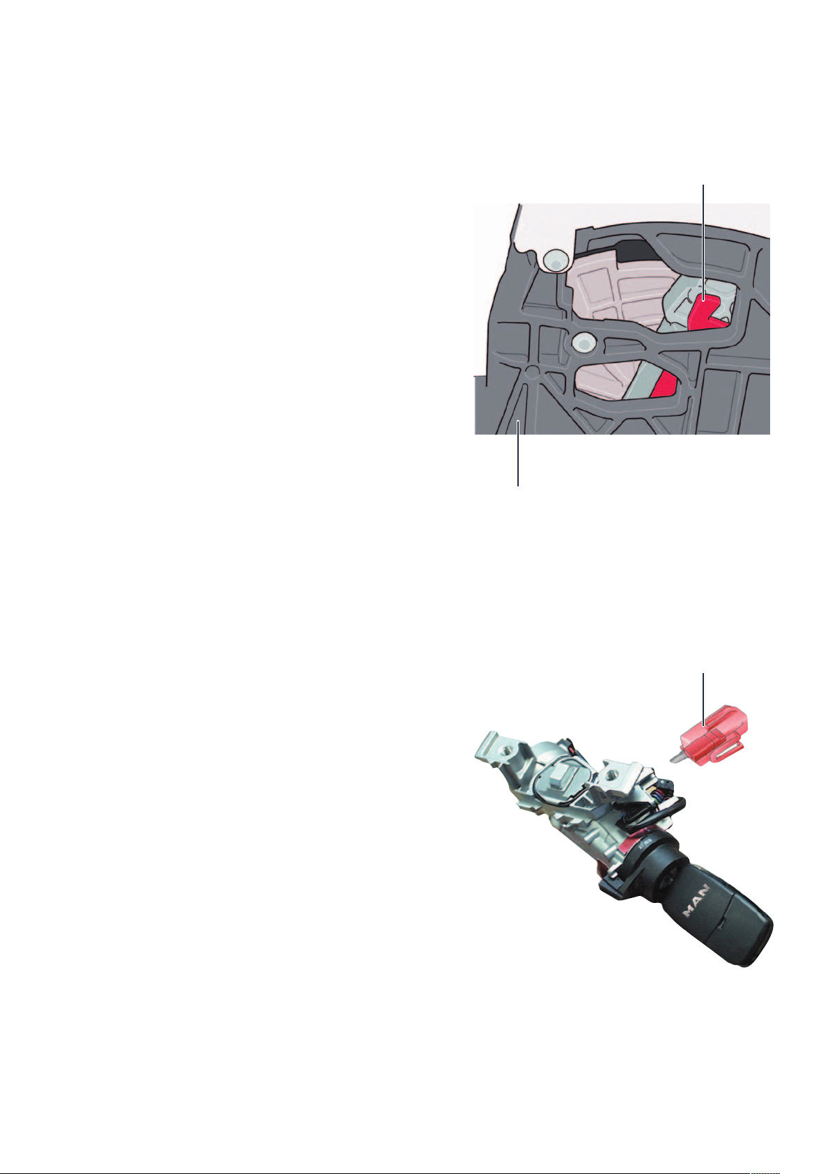
The mechanical, manual emergency release of the P latch
The locking lever for the emergency release is located on the right of
the selector mechanism.
To unlock the selector lever lock, pull the locking lever backwards and
press the selector lever lock button at the same time.
Locking lever
m107_025
Selector mechanism
The ignition key withdrawal lock
The ignition key withdrawal lock prevents the ignition key from being
turned back to the withdrawal position if the parking lock is not
engaged.
It functions electromechanically and is controlled by the steering
column electronics control unit J527.
The control unit for steering column electronics detects the position
of switch F319. If the switch is open, the selector lever is in “P”, the
solenoid for ignition key withdrawal lock N376 is not energised. The
ignition key can be removed.
Locking pin
m107_055
9
Page 10
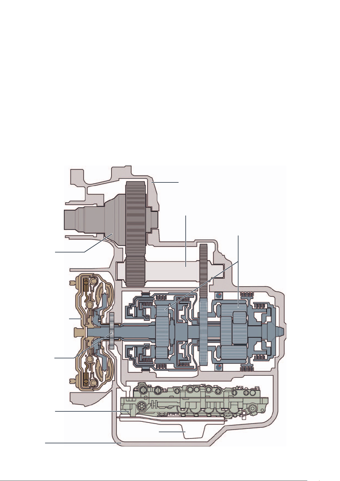
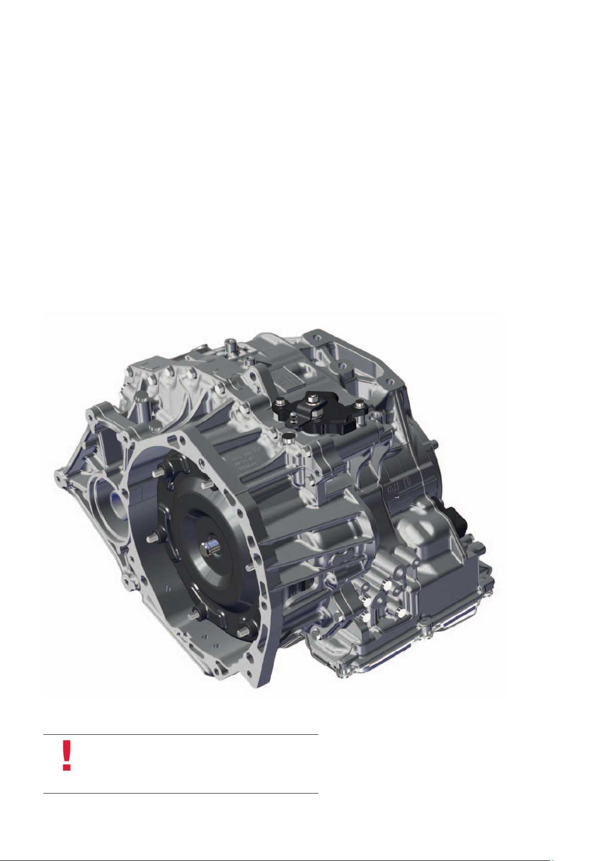
Gearbox deSIGn
The gearbox at a glance
The gearbox is divided into the following main
assemblies:
The torque converter with torque converter lock-up
clutch
− for front-wheel drive without centrifugal pendulum
− for four-wheel drive with centrifugal pendulum
The ATF oil pump
Differential
The planetary gearbox
The valve body
The transfer box (only for four-wheel drive)
The automatic gearbox control unit (in the engine
compartment)
Gearbox housing
Intermediate shaft
Planetary gearbox
Torque converter
ATF pump
Valve body
Sump
10
Oil filter
m107_002
Page 11
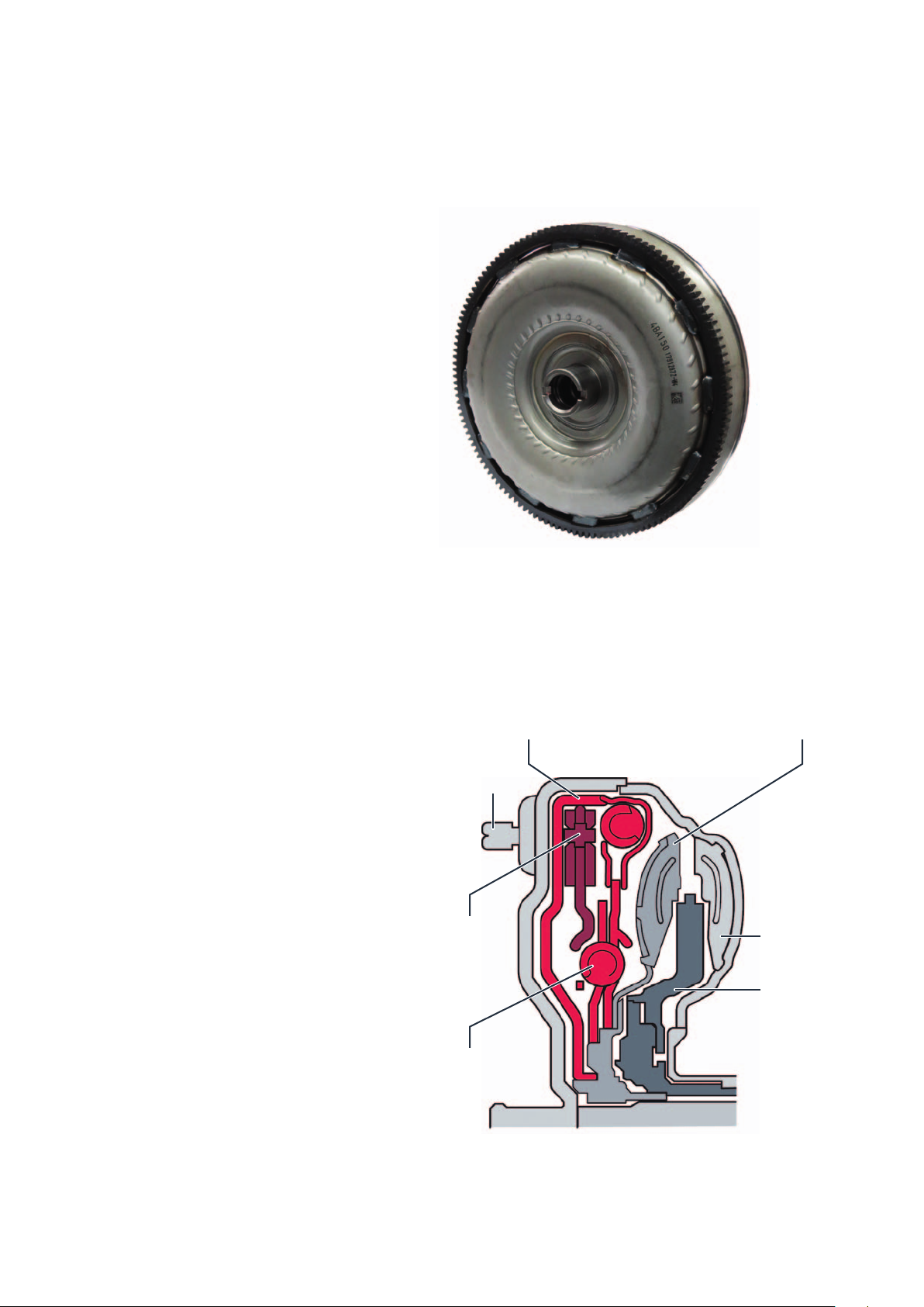
Torque converter
The hydromechanical torque converter is a fluid
coupling. It serves as a driving off element and boosts
the torque in the conversion range. Alongside the
turbine wheel, pump wheel and stator, a torque
converter lock-up clutch is fitted in the torque
converter. The torque converter of the fourwheel
driveversion of the TGE has what are referred to as
centrifugal pendulums to compensate for torsional
vibrations in the engine more efficiently.
During operation, their inertia causes them to oscillate
in the opposite direction to the engine oscillations, thus
largely compensating for them. The torque converter is
connected to the various engines via a driving plate
with six studs, which are permanently connected to
the torque converter.
m107_043
Alongside the turbine wheel, pump wheel and stator, a
torque converter lock-up clutch is fitted in the torque
converter.
An optimised torsional damper is used in the torque
converter of the TGE. In addition, torque converters in
four-wheel drive vehicles have integrated centrifugal
pendulums. Torsion dampers and centrifugal
pendulums reduce the transmission of torsional
vibrations from the engine to the drive train.
Torque converter lock-up clutch
Stud
Centrifugal
pendulum
absorbers
Torsional damper
Turbine
Pump impeller
Stator
m107_018
11
Page 12

Gearbox deSIGn
The planetary gearbox
Like its predecessors, this automatic gearbox also has
two planetary gear sets arranged one behind the other.
The first planetary gear set is a single planetary
gearbox.
The second planetary gear set is a double planetary
gearbox based on the Ravigneaux principle. This
special arrangement of the two different planetary gear
sets is called a Lepelletier planetary gearbox.
The first planetary gear set makes it possible to drive
the second planetary gear set at two different speeds.
Due to this special design, it is possible to implement
amaximum of 9 gears (10 minus 1). This means that
gearboxes with this design have an extremely wide
range of applications from 5-speed automatic gearboxes to the 8-speed automatic gearbox described
here. They differ essentially only in the number of
clutches and brakes required to implement the
respective number of gears.
m107_044
m107_056
12
Single planetary gear set Double planetary gear set
according to Ravigneaux
Planetary gearbox according to Lepelletier
Page 13

The single planetary gear set
From the torque converter, the drive torque of the
engine passes from the gearbox input shaft via the
planetary gear carrier PT1 to this planetary gearbox.
The sun gear S1 is permanently connected to the ATF
oil pump via a plug connection. This means it cannot
m107_045
rotate freely. The planetary gear carrier PT1 has five
planetary gears for transmission to the annulus H1.
The single planetary gearbox is integrated into the
gearbox via theclutches K1, K3 and K4 as well as the
brake B1.
Planetary gear
carrier PT1
Input shaft
Sun gear S1
Brake B1 Annulus H1
Clutch K4 Clutch K3 Clutch K1
m107_022
13
Page 14

Gearbox deSIGn
The double planetary gear set according to Ravigneaux
The clutches K1, K3 and K4 on the single planetary
gearbox and the clutch K2 on the Ravigneaux
planetary gearbox transmit the engine torque to this
double planetary gearbox. This is done either from the
gearbox input shaft via the single planetary gear set
described above to the sun gears S2 or S3 or via the
clutch K2 directly from the gearbox input shaft to the
planetary gear carrier PT2.
The two sun gears S2 and S3 can rotate at different
speeds. On the planetary gear carrier there are three
planetary gears of different lengths P2a and P3a. The
short planetary gears P2a engage in the sun gear S2
and the annulus H2 and the long planetary gears P3a
engage in the annulus H2 and via inner planetary gears
P3b on the sun gear S3. The double planetary gear set
is integrated into the gearbox via the clutch K2, the
brake B2 and the freewheel.
Output to
differential
Connection K3 and K4
with sun gear S2
Input shaft
Connection K1 with
sun gear S3
m107_047
Annulus H2 Brake B2
Planetary gear carrier PT2
Intermediate shaft
(turbine shaft)
14
m107_023
Sun gear S2 Sun gear S3 Clutch K2
Page 15

The brakes
Brake B1
Brake B1 is a band brake. It is connected to the
gearbox housing and is operated hydraulically by
means of a control piston via the valve body.
Brake B1 is controlled using the automatic gearbox
pressure regulating valve 2. The return movement is
performed using a spring.
When applied, it holds the sun gear S2, when K4 is
closed it holds the planetary gear carrier PT1, when K3
is closed it holds the annulus H1 and when K1 is
closed it holds the sun gear S3.
m107_027
Brake B1
Brake B2
Brake B2 is designed as a multi-disc brake. It is
connected to the gearbox housing.
When the solenoid valve 1 N88 is energised, the
hydraulic oil pressure compresses the discs of the
brake.
The planetary gear carrier PT2 is held in this way.
m107_029
B1 PT1 H1 S2 S3
m107_028
Brake B2
B2 PT2
m107_030
15
Page 16

Gearbox deSIGn
The clutches
The clutches K1, K2, K3 and K4
The electric solenoid valves inside the valve body open
or close the clutches. The clutches fulfil the following
functions when closed:
Clutch K1 connects the annulus H1 with the sun
gear S3.
Clutch K2 connects turbine shaft to the planetary
gear carrier PT2.
Clutch K3 connects the annulus H1 with the sun
gear S2.
Clutch K4 connects the planetary gear carrier PT1
to the sun gear S2.
16
m107_031
Clutch K4 Clutch K3 Clutch K1 Clutch K2
Page 17

Parking lock
In order to protect the parking lock against
unnecessary mechanical wear, a new display concept
has been implemented in the TGE to prevent misuse
ofthe parking lock.
In this context, misuse means using the parking lock
as a service brake.
This means that the parking lock is engaged when the
vehicle is rolling in order to bring the vehicle to a
standstill. The parking lock serves exclusively to secure
the vehicle against rolling away and is only allowed to
be engaged when the vehicle is stationary.
The display concept works with two warning levels.
Warning level 1
m107_050
An acoustic warning tone of priority level 2 sounds.
The display of the dash panel insert shows the
adjacent warning message for six seconds.
Warning level 2
An acoustic warning tone of priority level 1 sounds.
The display of the dash panel insert shows the
adjacent warning message for six seconds.
In addition, the central warning lamp lights up red.
The display of this warning level repeats itself with
each engine start.
Warning level 2 cannot be reset. The gearbox must
berenewed.
Only engage P
when stationary!
Wear of the
parking lock!
m107_052
Parking lock
damaged by misuse.
Use handbrake.
Workshop!
m107_053
17
Page 18

valve body
The valve body at a glance
The valve body is screwed into the gearbox housing
from below. The clutches and brakes of the gearbox
are actuated by means of hydraulic valves, so-called
shift valves, inside the valve body. The shift valves are
controlled by electrically operated solenoid valves,
which in turn are controlled by the automatic gearbox
control unit J217. In addition to the shift valves, the
valve body controls the torque converter and the
various pressures in the gearbox, e.g. main, control,
converter and lubricating pressure.
To achieve the required oil pressure in start-stop
operation, an auxiliary hydraulic pump 1 for gearbox oil
V475 is installed in the valve body.
Solenoid valve 2 N89 (solenoid valve)
Pressure regulating valve 1 for automatic
gearbox N215 (falling characteristic)
Selector slide
Gearbox oil temperature sender G93
The valve body contains the following components:
The mechanically operated selector slide valve
Two electrically controlled solenoid valves
(3/2-way valves)
Six electric pressure regulating valves with
increasing characteristic curve (pressure increases
with increasing control current)
One electric pressure regulating valve with falling
characteristic (pressure decreases with increasing
control current)
The gearbox oil temperature sender G93
The electric auxiliary hydraulic pump 1 for gearbox
oil V475
Solenoid valve 1 N88 (solenoid valve)
Pressure regulating valve 3 for automatic
gearbox N217 (rising characteristic)
Auxiliary hydraulic
pump1 for gearbox oil
V475
Pressure regulating
valve 8 for automatic
gearbox N510
(rising characteristic)
Pressure regulating
valve 6 for automatic
gearbox N371
(risingcharacteristic)
m107_019
Pressure regulating valve 5 for automatic
gearbox N233 (rising characteristic)
18
Pressure regulating valve 4 for automatic
gearbox N218 (rising characteristic)
Pressure regulating valve 2 for automatic
gearbox N216 (rising characteristic)
Page 19

Solenoid valves
Gears
P R N 1 2 3 4 5 6 7 8
Solenoid valve 1 N88 – – – X – – – – – – –
Solenoid valve 2 N89 – – – – X X – – – – –
Pressure regulating valve 1 for
automatic gearbox N215
Pressure regulating valve 2 for
automatic gearbox N216
Pressure regulating valve 3 for
automatic gearbox N217
Pressure regulating valve 4 for
automatic gearbox N218
Pressure regulating valve 5 for
automatic gearbox N233
Pressure regulating valve 6 for
automatic gearbox N371
Pressure regulating valve 8 for
automatic gearbox N510
The pressure regulating valve 1 modulates the main oil pressure of the gearbox
depending on of the accelerator pedal value.
– – – – X – – – – – X
– – – X X X X X – – –
– – – – – – – X X X X
– X – – – X – – – X –
– – – – – – X – X – –
The pressure regulating valve 8 modulates the oil pressure for the torque converter
lock-up clutch depending on the shift strategy.
Clutches
Gears
P R N 1 2 3 4 5 6 7 8
Clutch K1 – – – X X X X X – – –
Clutch K2 – – – – – – – X X X X
Clutch K3 – X – – – X – – – X –
Clutch K4 – – – – – – X – X – –
Brakes/freewheel
Gears
P R N 1 2 3 4 5 6 7 8
Brake B1 – – – – X – – – – – X
Brake B2 – X – X* – – – – – – –
Gliding – – – X – – – – – – –
– = Valve switched off, clutch open, brake not applied
X = Valve switch on, clutch closed, brake applied
X* = Only closed in Tiptronic mode in 1st in certain driving situations to use the
engine braking effect
19
Page 20

oIl Supply
The ATF oil pump
In the case of vehicles with internal combustion
engines, the mechanical ATF pump (Automatic
Transmission Fluid) is exclusively responsible for the
supply of hydraulic oil to the gearbox during normal
driving. It draws the ATF oil from the oil sump, builds
up the oil pressure and supplies the valve body with
the hydraulic fluid required for the gear changes.
m107_054
The ATF oil pump is an internal geared wheel pump
(duocentric oil pump). It is driven directly by the engine
via the converter housing by the converter hub. Here,
m107_012
the drive lugs of the pinion of the ATF oil pump engage
in two grooves on the converter hub.
20
Page 21

Auxiliary hydraulic pump 1 for gearbox oil V475
The electric oil pump is required for vehicles with
start-stop system. It maintains the oil pressure in the
gearbox during the stop phase. This allows the vehicle
to move off immediately after the engine starts without
any loss of comfort.
After the internal combustion engine has started again
and the mechanical oil pump has built up the required
oil pressure, the auxiliary hydraulic pump 1 for gearbox
oil is switched off.
m107_020
m107_021
21
Page 22

Gearbox manaGement
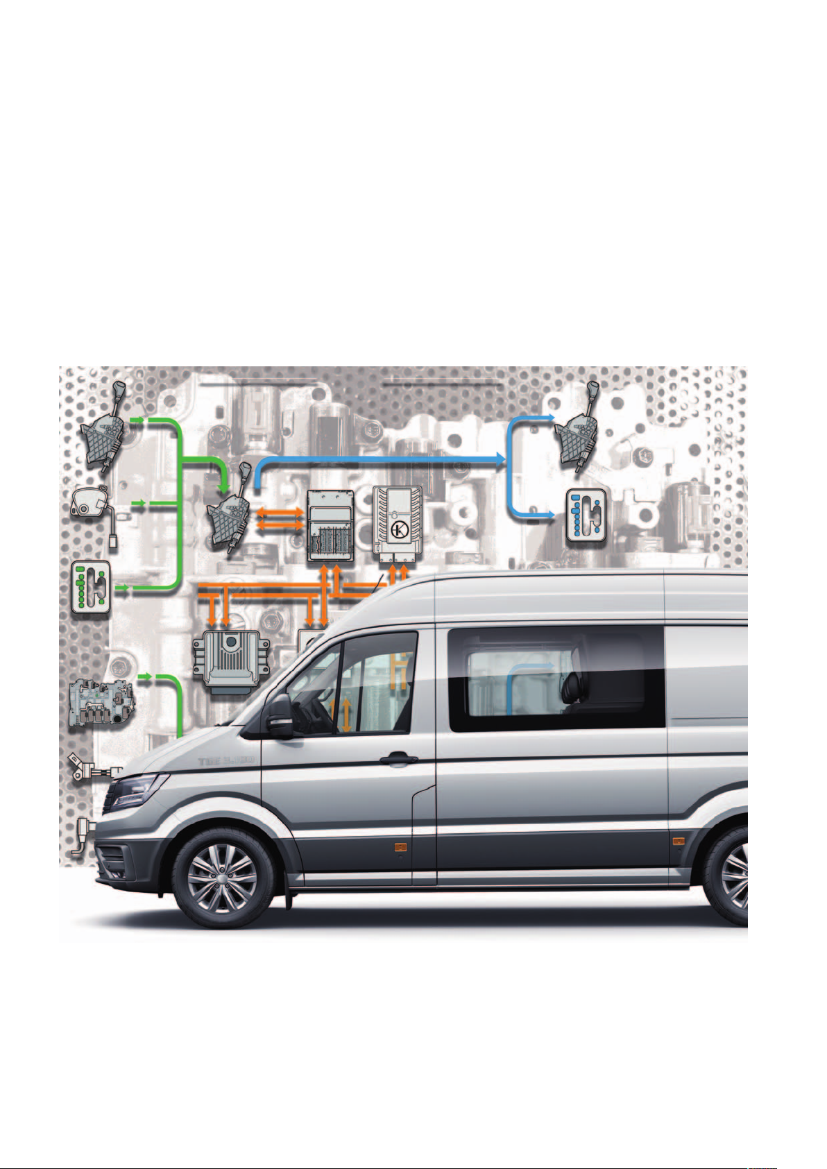
System overview
Sensors
Reversing switch
F41
Gearbox position switch
F305
Selector lever locked in position P switch
F319
Multifunction switch
F125
On-board power
supply control unit
J519
Tiptronic switch
F189
Gearbox oil temperature sender
G93
Gearbox input speed sender
G632
Selector lever sensors
control unit
J587
Data bus diagnostic
interface J533
Automatic gearbox
control unit
J217
Control unit in dash
panel insert
J285
22
Gearbox output speed sender
G195
Page 23

Engine control unit
J623
Actuators
Selector lever lock solenoid
N110
Solenoid for selector lever lock P
N380
Selector lever position display
Y6
Steering column
electronics control
unit J527
Solenoid valve 1
N88
Solenoid valve 2
N89
Pressure regulating valve 1 for automatic gearbox N215
Pressure regulating valve 2 for automatic gearbox N216
Pressure regulating valve 3 for automatic gearbox N217
Pressure regulating valve 4 for automatic gearbox N218
Pressure regulating valve 5 for automatic gearbox N233
Pressure regulating valve 6 for automatic gearbox N371
Pressure regulating valve 8 for automatic gearbox N510
Auxiliary hydraulic pump 1 for gearbox oil
V475
m107_038
23
Page 24

Gearbox manaGement
The automatic gearbox control unit J217
The automatic gearbox control unit J217 is located in
the engine compartment at the front left under the
battery console of the additional battery.
It is connected to the diagnostic interface for data bus
via the powertrain CAN bus.
The automatic gearbox control unit directly controls
the solenoid valves in the valve body.
The information from the sensors in the gearbox is also
transmitted directly. For this reason, the control unit is
connected to the on-board electrical system and the
gearbox via a 52-pin plug.
The VAS adapter cable 1598/48 is available for static
and dynamic measurements on the system.
The manufacturer of the control unit is also AISIN AW
Japan. The update programming is possible with the
VAS 5051.
The dynamic shift program DSP is integrated in the
control unit. This shift program evaluates the driving
resistance (e.g. for driving on hilly terrain), the route
profile (e.g. for windy roads) and the driving style,
amongst other factors, to determine the gearshift
points.
24
m107_037
Page 25

The torque characteristics
The torque curves of the individual gears are shown in
the following highly simplified cross-section of the
gearbox. The illustration of the valve body shows
1st gear
PT1
which solenoid valves are activated for the respective
gear.
H1
K1
H2
P2
P3
S3
B2
PT2
Clutch K1 and freewheel F
The gearbox input shaft transmits the engine torque to
the planetary gear carrier PT1 of the single planetary
gear set. The planetary gears P1 roll around supported
on the fixed sun gear S1 and drive the annulus H1.
Clutch K1 connects the planetary gear carrier H1 to
the sun gear S3 and, in this way, transfers the torque
to the double planetary gear set. The freewheel blocks
the planetary gear carrier PT2. From the sun gear S3,
the torque is transferred to the planetary gears P3.
Supported by the planetary gear carrier PT2, the
torque is transferred to the annulus H2.
Annulus H2 is connected to the gearbox output shaft.
N88
N217
In certain driving situations, the braking effect of the
engine can be used by selecting 1st gear in Tiptronic
mode.
Using the engine braking effect in 1st gear is made
possible by closing the brake B2.
Brake B2 blocks the planetary gear carrier PT2
similarly to the freewheel. Unlike the freewheel F,
however, the brake B2 holds the planetary gear carrier
PT2 in both directions of rotation.
m107_003
25
Page 26

Gearbox manaGement
2nd gear
B1
PT1
H1
N217
K1
N89
N216
P2
H2
P3
S3
PT2
m107_004
Clutch K1 and brake B1
As with the first gear, the engine torque is introduced
into the double planetary gear set by the annulus H1 of
the single planetary gear set. Clutch K1 connects the
annulus H1 to the sun gear S3 for this purpose.
26
Brake B1 blocks the sun gear S2. From the sun gear
S3, the torque is transferred to the planetary gears P3.
Planetary gears P2 roll around the sun gear S2 and,
together with the planetary gears P3, drive annulus H2.
Page 27

3rd gear
K3
PT1
H1
K1
N89
P2
S2
H2
P3
S3
PT2
Clutches K1 and K3
As before, the clutch K1 connects the annulus H1 to
the sun gear S3.
Clutch K3 additionally connects the annulus H2 to the
large sun gear S2.
N217
N233
m107_005
Planetary gears P2 and P3 are blocked by K1 and K3.
Planetary gear carrier PT2 now rotates together with
the sun gears S2 and S3.
The torque is thus transmitted via the planetary gear
carrier PT2 to the annulus H2.
27
Page 28

Gearbox manaGement
4th gear
K4
PT1
H1
N217
K1
P2
S2
H2
P3
S3
N371
PT2
m107_006
Clutches K1 and K4
Once again, the clutch K3 connects the annulus H1 to
the sun gear S3 and, in this way, transfers the torque
to the double planetary gear set.
Clutch K4 connects the planetary gear carrier PT1 to
the sun gear S2 and also transfers the torque to the
double planetary gear set, although with different input
speeds.
28
Sun gear S3 is driven more slowly than the sun
gearS2. Planetary gears P2/P3 roll around the fasterrotating sun gear S2 and drive the annulus H2.
Page 29

5th gear
PT1
H1
N217
K1
N218
P2
H2
P3
S3
K2
PT2
m107_007
Clutches K1 and K2
Clutch K1 connects the annulus H1 to the sun gear S3
and, in this way, transfers the torque to the double
planetary gear set. The clutch K2 connects the turbine
shaft to the planetary gear carrier PT2 and thereby
transfers the torque to the double planetary gear set in
the same way.
Together with the planetary gear carrier PT2, planetary
gears P2 and P3 drive the annulus H2.
29
Page 30

Gearbox manaGement
6th gear
K4
PT1
H1
N217
P2
S2
H2
P3
N371
K2
PT2
m107_008
Clutches K2 and K4
The turbine shaft drives the planetary gear carrier PT1
of the single planetary gear set and the outer disc
carrier of the clutch K2. The clutch K4 connects the
planetary gear carrier PT1 to the sun gear S2 and, in
this way, transfers the torque to the double planetary
gear set.
The clutch K2 connects the turbine shaft to the
planetary gear carrier PT2 and thereby transfers the
torque to the double planetary gear set in the same
way.
30
Sun gear S2 transfers the torque to the planetary
gears P2. The torque is transferred to the planetary
gears P3 via the planetary gear carrier PT2. Together
with the planetary gears P2, the planetary gears P3
drive the annulus H2.
Page 31

7th gear
K3
H1
H2
K2
PT1
N218
N233
P2
S2
P3
PT2
m107_009
Clutches K2 and K3
The turbine shaft drives the planetary gear carrier PT1
of the single planetary gear set and the outer disc
carrier of the clutch K2. Planetary gear carrier PT1
drives the planetary gears P1, which roll around
supported on the fixed sun gear S1 and thus drive the
annulus H1.
Clutch K3 connects the annulus H1 to the sun gear S2
and, in this way, transfers the torque to the double
planetary gear set.
The clutch K2 connects the turbine shaft to the
planetary gear carrier PT2 and, in this way, likewise
transfers the torque to the double planetary gear set.
The planetary gears P2, which are jointly driven by sun
gear S2 and planetary gear carrier PT2, drive the
annulus H2 along with the permanently connected
outer planetary gears P3a.
31
Page 32

Gearbox manaGement
8th gear
B1
PT1
H1
N218K2N216
P2
S2
H2
P3
PT2
m107_010
Clutches K2 and brake B1
Brake B1 blocks the sun gear S2. Clutch K2 connects
the turbine shaft to the planetary gear carrier PT2 of
the double planetary gear set and, in this way,
transfers the torque to the double planetary gear set.
32
The long planetary gears P3 roll around the stationary sun
gear S2 and, together with the planetary gears P2, drive
the annulus H2. The clutches K1 and K3 are open.
The single planetary gear set is not part of the power flow.
Page 33

Reverse gear
K3
H1
B2
H2
PT1
N233
P2
S2
P3
N510
PT2
m107_011
Clutches K3 and brake B2
The turbine shaft drives the planetary gear carrier PT1
of the single planetary gear set. The planetary gear
carrier PT1 drives the planetary gears P1, which roll
around supported on the fixed sun gear S1.
The annulus H1 is driven in this way.
Clutch K3 connects the annulus H1 to the sun gear S2
and, in this way, transfers the torque to the double
planetary gear set. In the double planetary gear set,
brake B2 blocks the planetary gear carrier PT2.
From the sun gear S2, the torque is transferred to the
planetary gears P2 and P3. Supported by the
planetary gear carrier PT2, the torque is transferred
tothe annulus H2, which is connected to the output
shaft. Annulus H2 is thereby driven against the
direction of engine rotation.
33
Page 34

ServIce
Special tools
Special tools
Designation
T10173
Setting gauge
30-211A
Support bridge
Tool Use
To set the multifunction switch
m107_040
Holds the torque converter in position
when the engine and gearbox are
separated.
m107_041
Towing
Note
If the TGE with 8-speed automatic gearbox has to be
towed, the 50/50 rule must be strictly observed. This
means that it is only allowed to be towed at a maximum
speed of 50 km/h over a maximum distance of 50 km.
34
Page 35

teSt your knowledGe
Which answers are correct?
One or several of the given answers may be correct.
1. An automatic gearbox according to Lepelletier essentially consists of:
a) A double Lepelletier planetary gear set and a single Ravigneaux planetary gear set
b) An upstream single planetary gear set and a Ravigneaux double planetary gear set
c) Two single Lepelletier planetary gear sets
2. Which statement is correct?
a) The entire planetary gearbox has a multi-disc brake and a band brake.
b) The entire planetary gearbox has two band brakes.
c) The entire planetary gearbox has two multi-disc brakes.
3. What is new about the parking lock in the 8-speed automatic gearbox of the TGE?
a) There are no new features on the parking lock.
b) A new display concept has been developed intended to prevent the misuse of the parking
lock as a service brake.
c) The parking lock is mechanically designed in such a way that it cannot be used as a service
brake.
4. The auxiliary hydraulic pump 1 for gearbox oil V475 is:
a) Screwed onto the gearbox housing from the outside.
b) Screwed onto the left longitudinal member under the cabin, separately from the gearbox.
c) Integrated in the valve body.
Answers:
1. b); 2. a); 3. b); 4. c)
35
Page 36

MAN Truck & Bus SE
Dachauer Straße 667
80976 München
www.mantruckandbus.com
MAN Truck & Bus – A company of the MAN group
 Loading...