

Page 1
MAN GUIDE 106
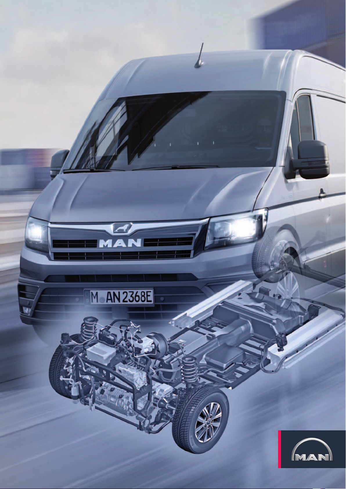
The eTGE
Page 2
The high-voltage components and the technologies used for the remaining subassemblies guarantee safe and comfortable
mobility. The electric motor boasts a power output of 100 kW and develops a maximum torque of 290 Nm from a standstill.
Depending on the vehicle payload, route and driving profile, the real range is approx. 120 km. According to the NEDC, the range
is 173 km. In the new, more challenging WLTC, the range is 110 / 114 km. The nominal energy of the lithium-ion high-voltage
battery is 35.8 kWh. The recuperation, i.e. the braking energy recovery, has been adapted for the eTGE with three-phase drive.
Under certain circumstances, the three-phase current drive can cause a deceleration when in alternator mode. The power and
control electronics for the electric drive supplies the energy generated to the high-voltage battery. Withthe eTGE, MAN is paving
the way for sustainable, future-proof mobility.
Technical status April 2019
2
m106_002
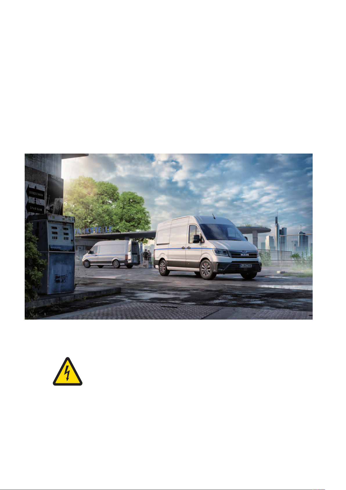
Attention! Dangerous electric voltage!
The eTGE is a battery-driven electric vehicle. It features a high-voltage system with a rated voltage
of 323 volts. This voltage level can be fatal. Only qualified employees may perform work on this
vehicle. The minimum qualification required is an electrically instructed person.
Page 3
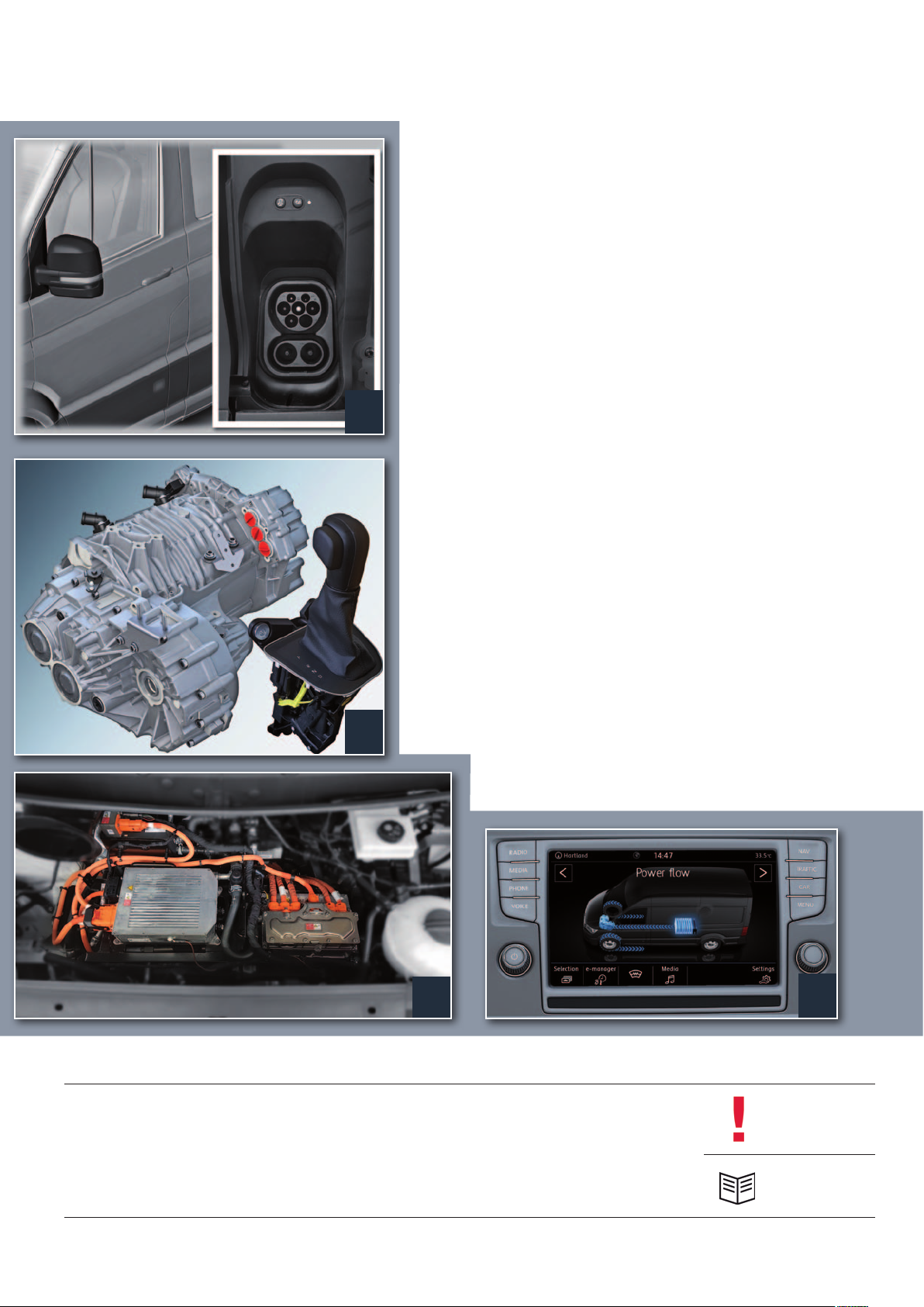
taBle of contents
4 IntroductIon
6 Body
8 Power transmIssIon
10 HeatIng and aIr condItIonIng
16 drIver assIst systems
4
18 HIgH-voltage system
30 electrIcal system
8
38 InfotaInment
41 servIce
43 test your knowledge
18
38
The MAN TGE Guide teaches the basics of design and function for sales and after-sales of new vehicle models, new
vehicle components or new technologies.
The MAN TGE Guide is not a sales manual nor a repair guide! Specified values are for the sake of easy understanding
only and refer to the data status valid at the time the MAN TGE Guide was created.
The contents are not updated.
Please use the appropriate technical literature for customer advice, maintenance and repair work.
Note
Reference
3
Page 4
IntroductIon
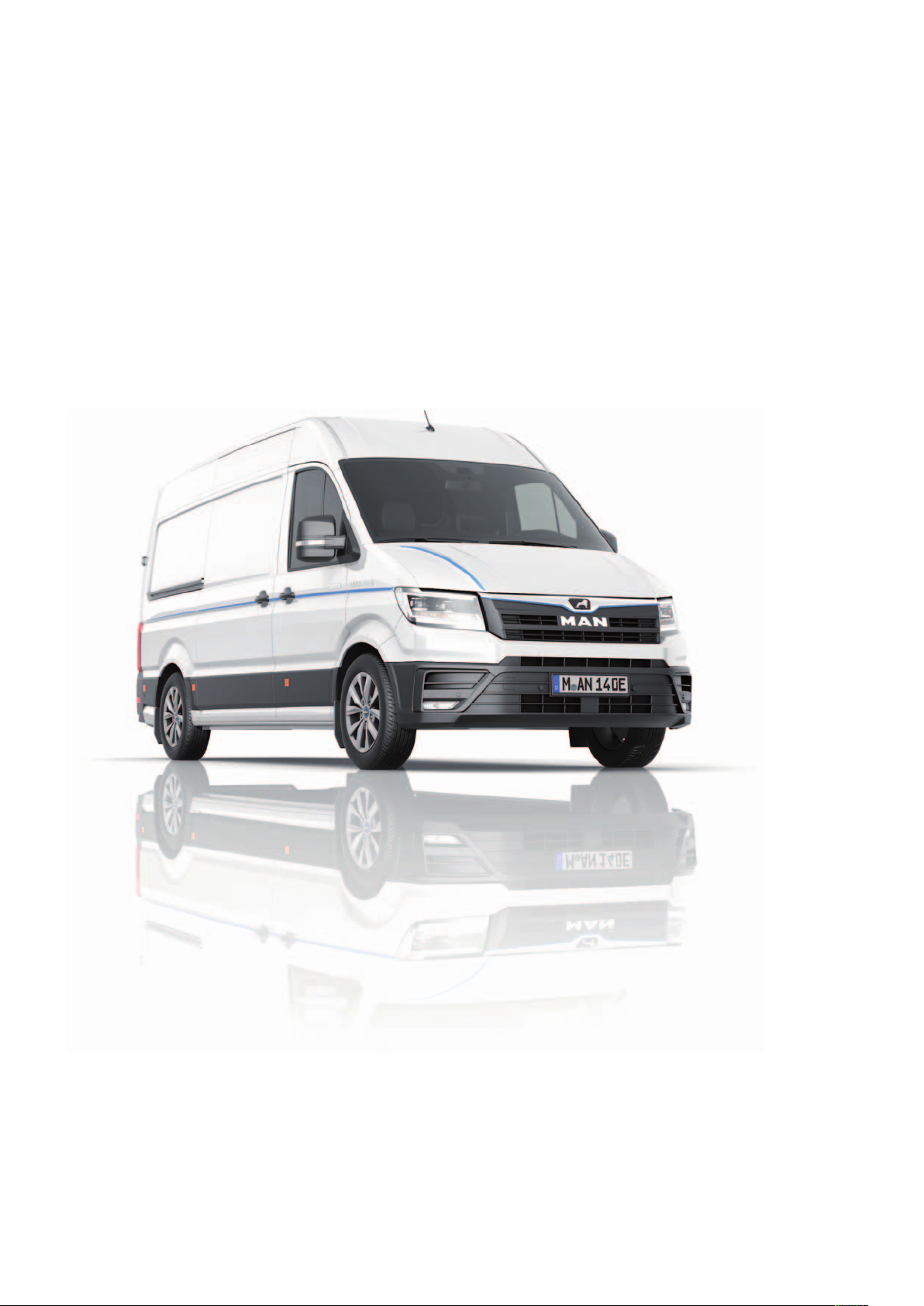
The eTGE
The electric van is based on the TGE 2017. Like the versions with diesel engines, the new eTGE
isalso equipped with state-of-the-art assistance and comfort systems.
Because the battery is integrated in the underbody, the charging volume of the electric version
withjust under 10.7 m
The payload of the eTGE is approx. 1.0 tonne at a gross vehicle weight of 3.5 tonnes.
3
remains at the level of the conventional models with rear-wheel drive.
m106_004
4
Page 5
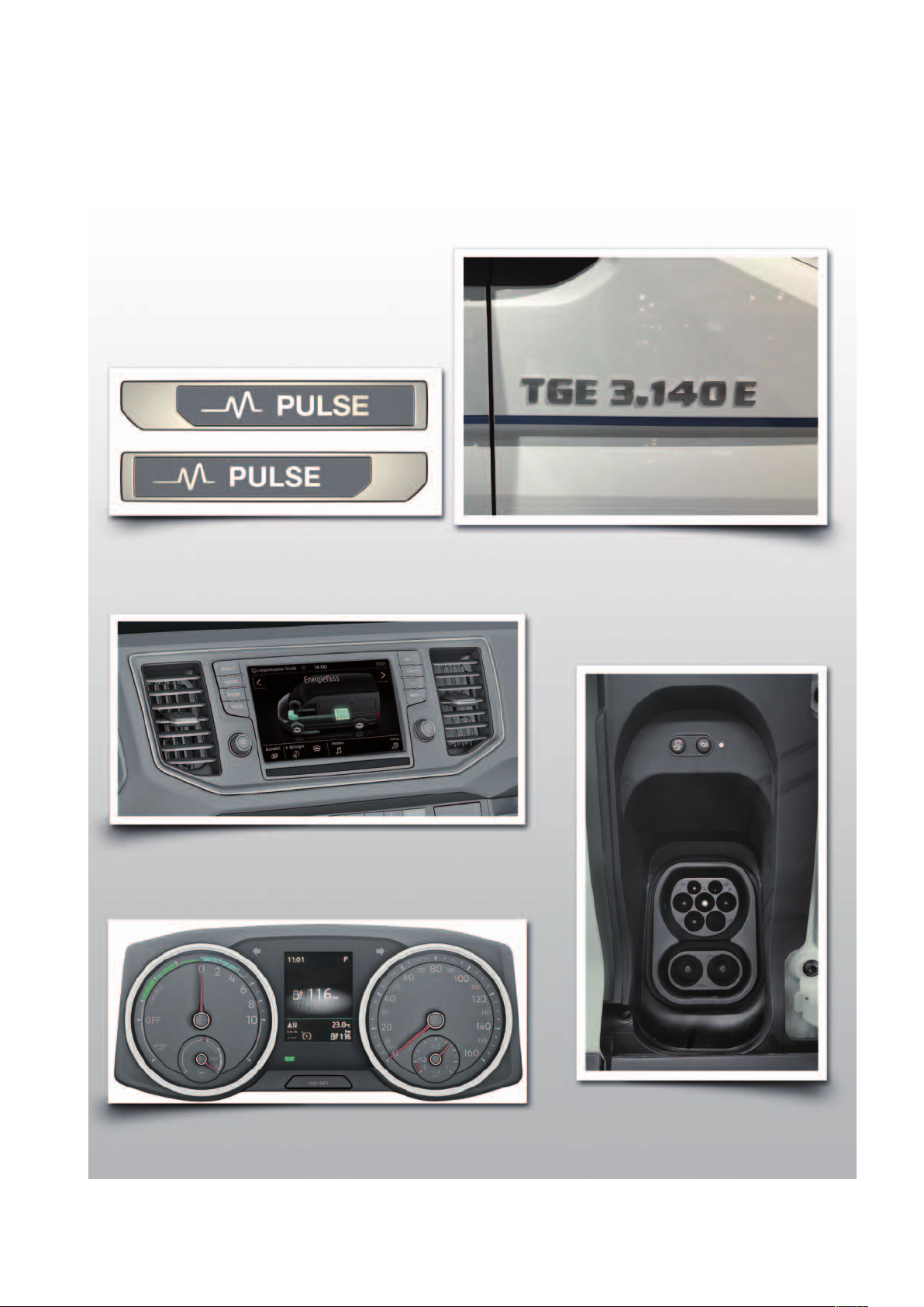
The characteristic features of the eTGE
eTGE emblems in the front grille, on the side panels, in front
of the wheel arches and at the rear left of the wing door at
the height of the tail light
e-specific displays in MAN Media Van Advanced
Instrument panel with e-specific displays
Charging socket behind the tank cap
m106_005
5
Page 6
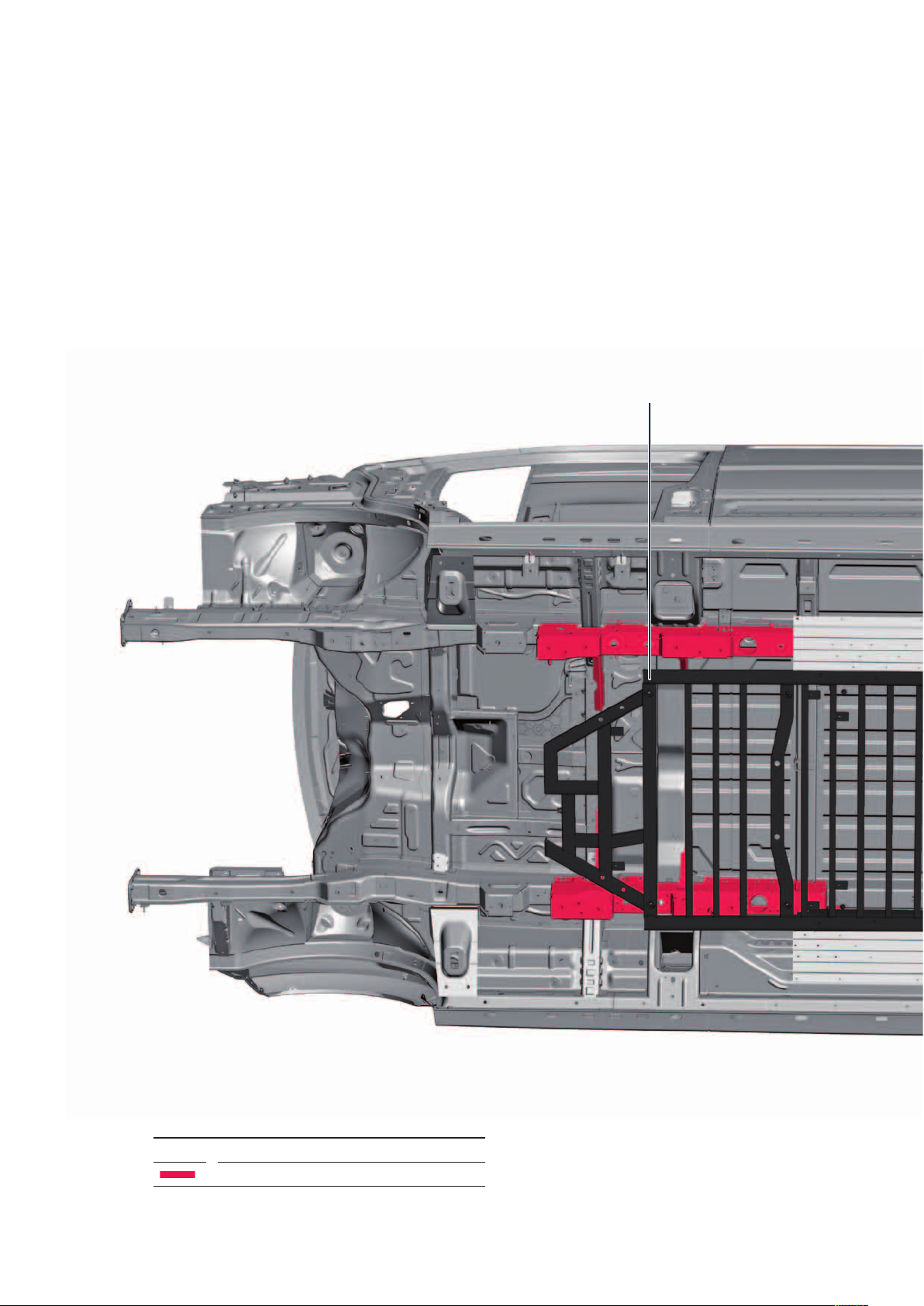
Body
Body structure
The body structure is based on the vehicle body
featured in the TGE 2017. In order to do justice to
crash safety requirements, the necessary changes to
the geometry were implemented in the underbody, and
additional components have been utilised.
Battery frame
Key
Body changes specifically for the eTGE
6
Page 7
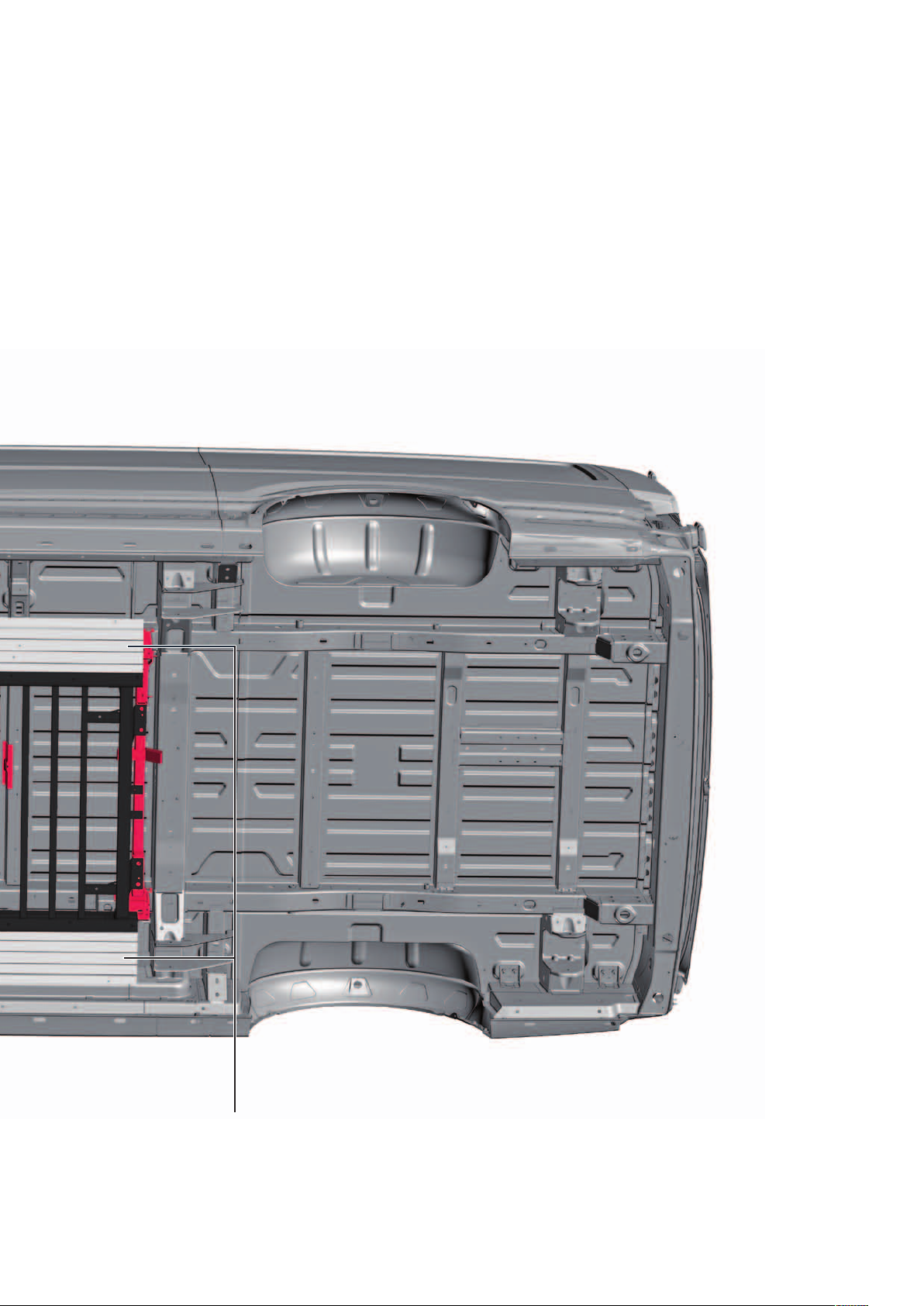
Underbody
The underbody has been extended, which allows
installation of the high-voltage battery, also allowing
thestricter impact requirements this involves to be
satisfied. In the lateral areas, additional crash elements
are installed between the high-voltage battery and the
sill panels. A support frame is located under the middle
of the underbody, which serves as protection for the
high-voltage battery from below. To protect against
dirt, and to improve the drag coefficient, the front of
the underbody features an underbody impact guard
and there are 4underbody covers in the middle.
Crash elements
m106_006
7
Page 8
Power transmIssIon
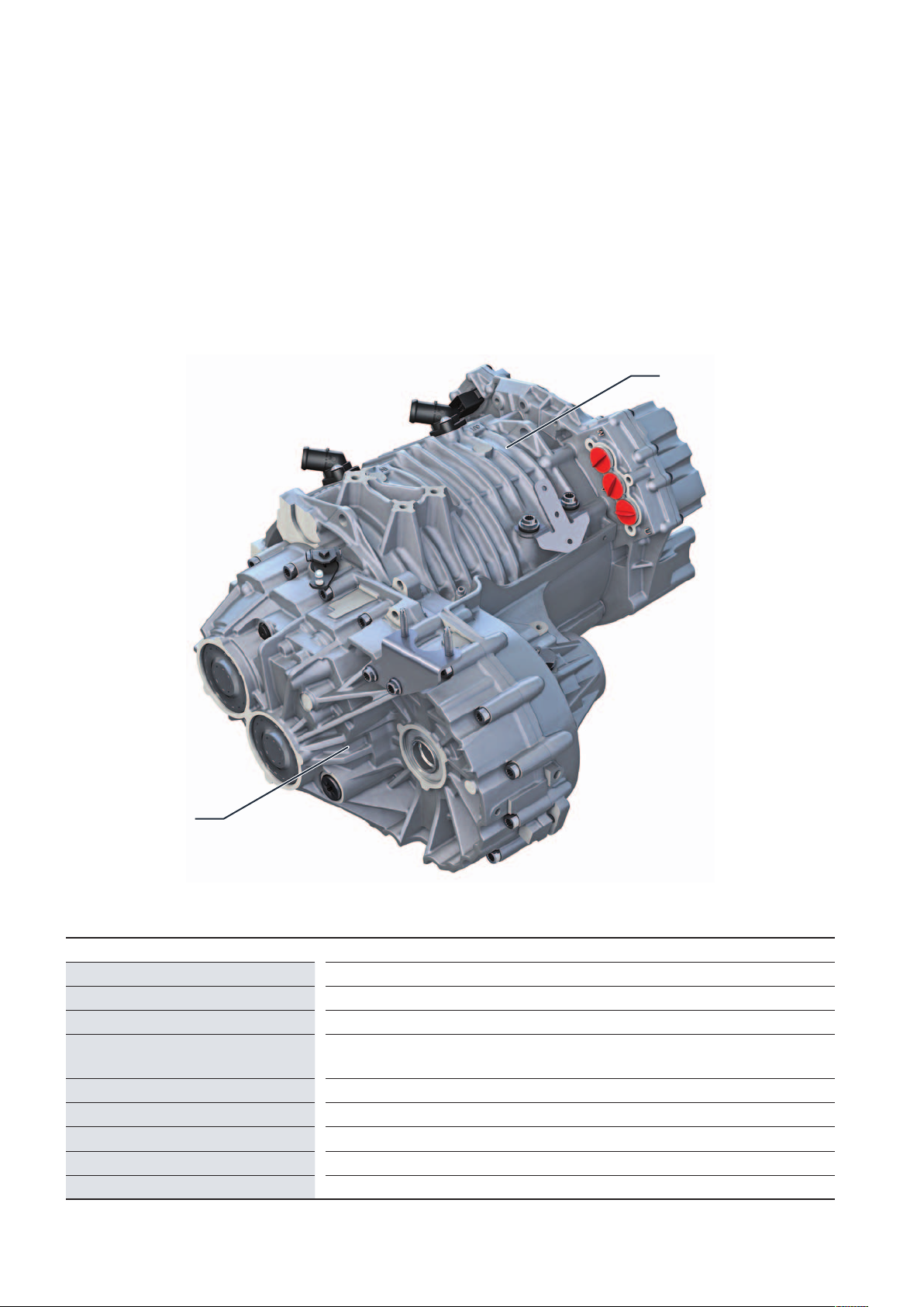
The 0MD 1-speed transmission
The 1-gear drive 0MD of the eTGE consists of proven
components of the group. Thereby, all components,
especially the lubrication in the gearbox, were optimally
designed to fulfil the high requirements in the
commercial vehicles sector.
Three-phase current drive VX54
1-speed transmission
0MD
Technical data
Transmission designation
Number of gears
Transmission stages
Transmission ratios
Max. input torque
Max. input speed
Weight (with oil)
Oil volume
Driveshafts
m106_007
0MD
1
2
Level 1: 3.192 (Z1 = 26; Z2 = 83)
Level 2: 3.609 (Z3 = 23; Z4 = 83)
290 Nm
12,000 rpm
32.2 kg
1.5 l
Splined connection
8
Page 9
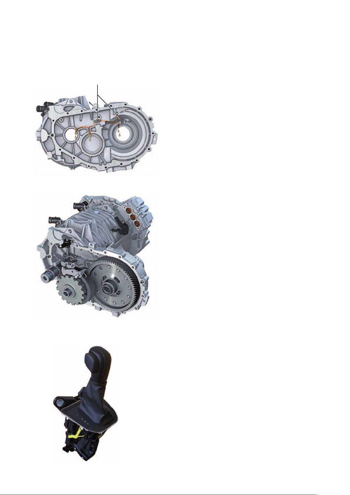
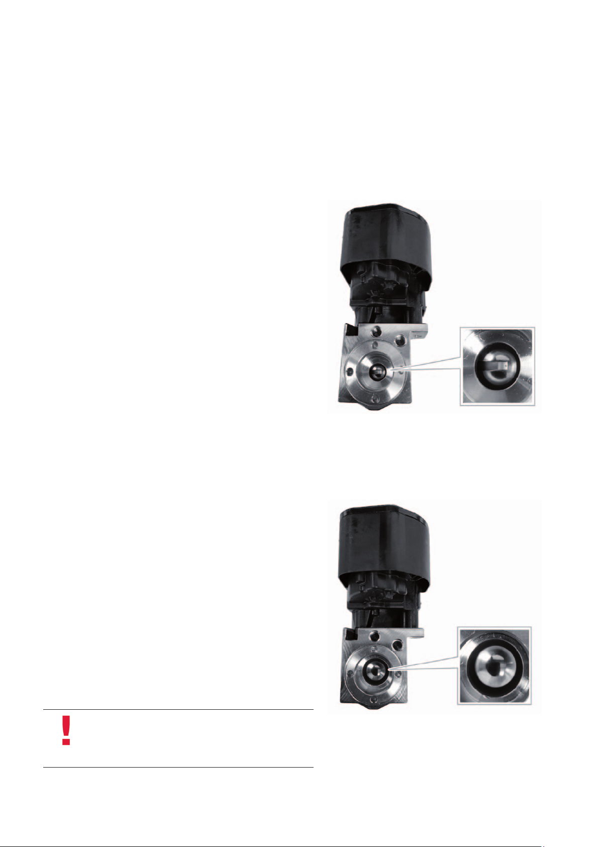
Oil supply system
Oil holes
m106_009
The 1-speed gearbox 0MD of the eTGE uses splash
lubrication. To ensure permanent lubrication, the final
drive gear runs in the oil sump. This requires an
appropriate design of the gearbox housing to ensure
lubrication, cooling and oil distribution. Lubrication of
the bearings for the drive shaft, drive shaft and axle
drive is ensured on the gearbox and motor housing
side by 2transverse bores and grooves behind the
bearing shells.
Other necessary measures:
Reinforced tapered roller bearings
Reinforced and larger parking lock
Reinforced toothing of the drive gears
Reinforced differential
Selector lever
m106_008
The 1-gear gearbox 0MD and the selector lever E313
are connected by a cable. This mechanical connection
is used only to activate the parking lock. The mechanical and electrical components of the selector lever are
installed in the housing of the selector lever E313. The
locking mechanism for the selector lever E313 is
provided by the selector lever lock solenoid N110. In
the event of a defect or a power failure, the selector
lever E313 remains locked. The manual emergency
release is located on the left of the selector mechanism. To unlock the selector lever lock, pull the locking
lever backwards and press the selector lever lock
button at the same time.
m106_010
9
Page 10
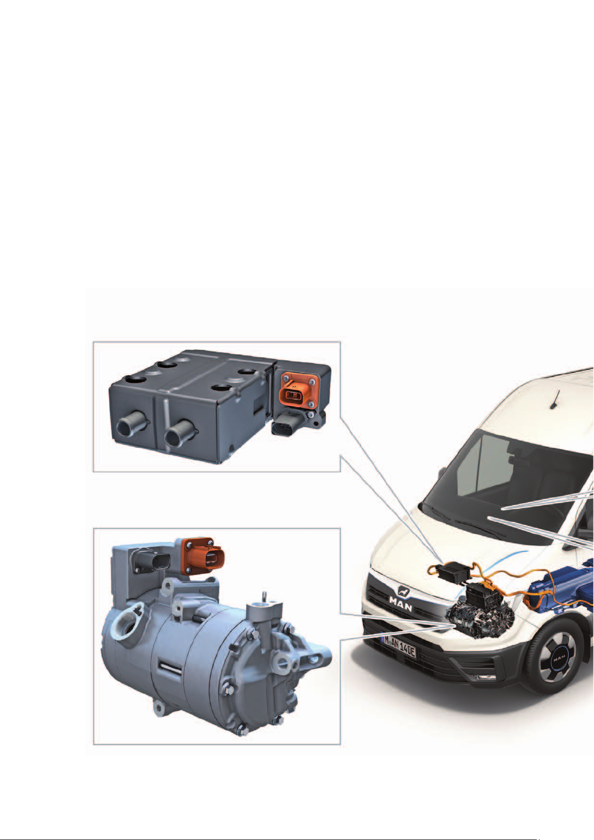
HeatIng and aIr condItIonIng
Overview of components
A 2-zone Climatronic is installed as series standard.
The interior air conditioning of the vehicle is carried out
entirely with a heat pump system via the operating
states “cooling” and “heating”. For cooling, the
refrigerant circuit is switched on in the same way as for
a normal air conditioning system. The system can
switch from cooling to heating via the modified control
of the expansion and shut-off valves. The hot
refrigerant coming from the compressor is passed over
the heating condenser and gives off its heat there to
the air flowing through, which heats the interior. The
Climatronic control unit J255 controls and monitors the
temperature sensors and the air and temperature flaps
in the interior. The thermal management control unit
J1024 controls, regulates and manages the expansion
valves, shut-off valves, high voltage heating (PTC)
Z115, electric air conditioning compressor and
refrigerant pressure and temperature senders.
High-voltage heater (PTC) Z115
Electrical air conditioner compressor V470
10
Page 11
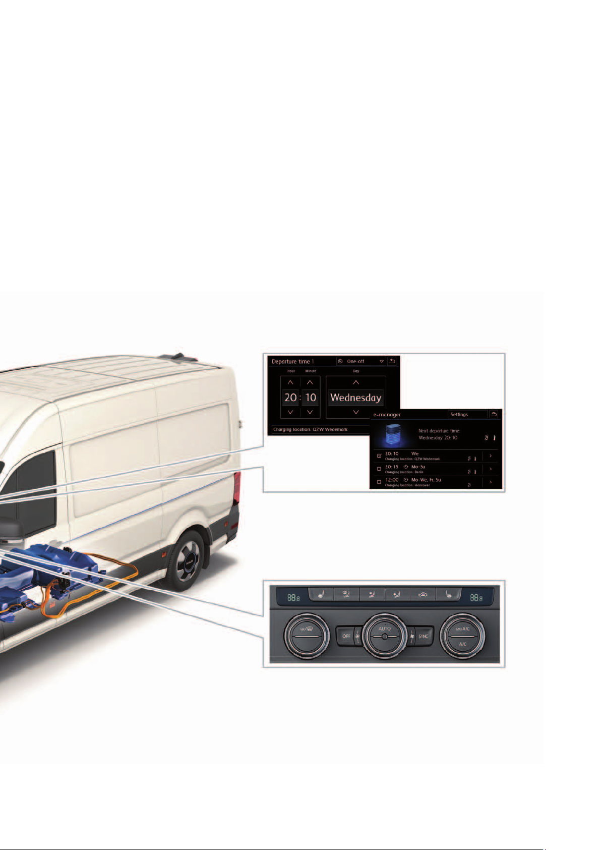
The high-voltage heating (PTC) Z115 and the electric
air conditioning compressor V470 operate on demand
from the air conditioning control unit for heating/
cooling. The set temperature request is sent via CAN
bus to the thermal management control unit J1024.
The e-Manager can be used to program the auxiliary
air conditioning with three departure times (timer).
e-Manager
Climatronic control unit J255
m106_011
11
Page 12
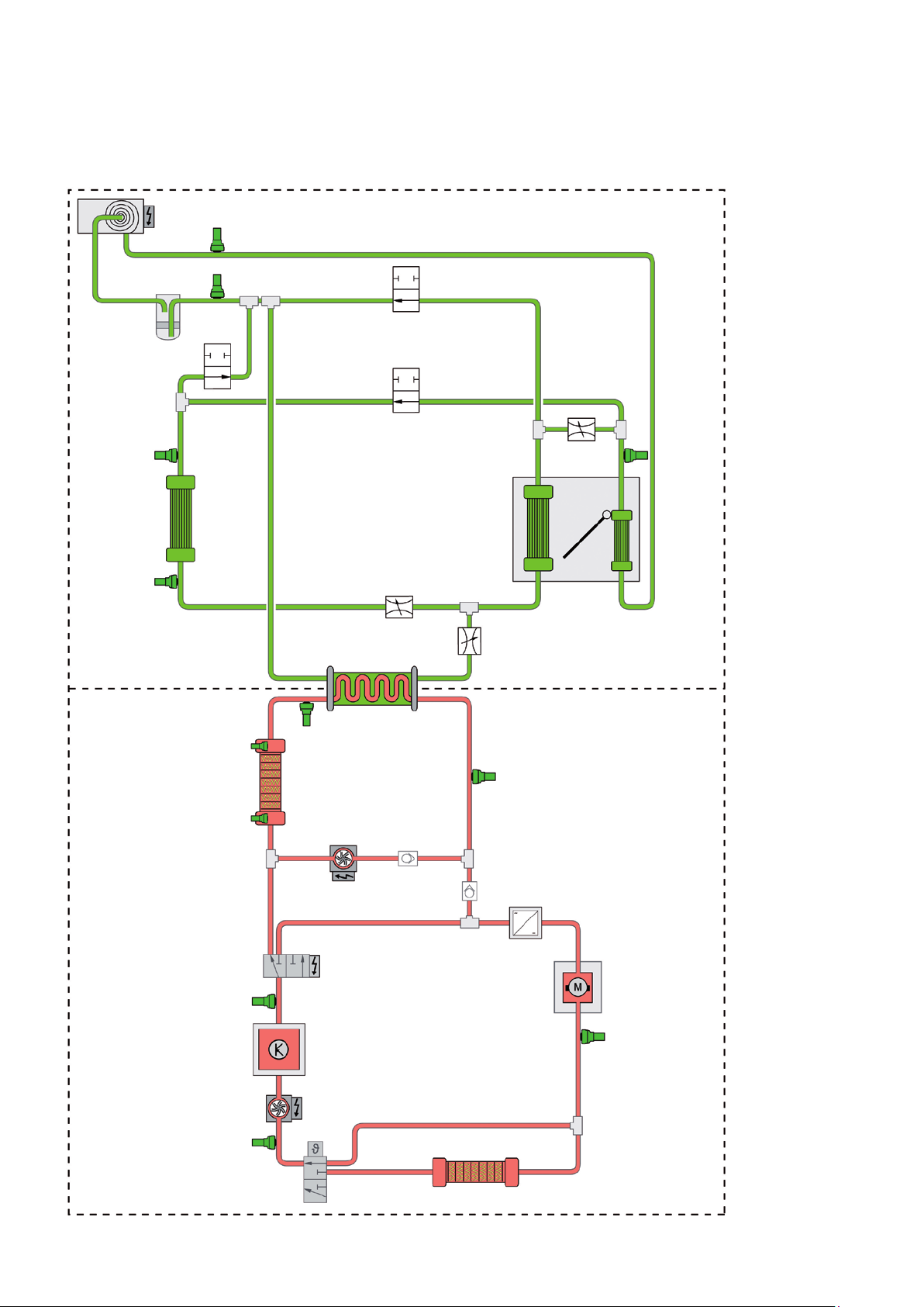
HeatIng and aIr condItIonIng
System overview
V470
G395
1
G827
2
G828
Refrigerant circuit
Coolant circuit
N643
G829
N642
N696
N636 G826
3
4
5
N637 N638
6
G785
N632
G789
JX1
V508
G83
9
G110
Z115
V509
G787
8
10
8
AX4
VX54
G788
m106_064
7
12
Page 13

Key
AX4
Charging unit 1 for high-voltage battery
G83 Radiator outlet coolant temperature
sender
G110 Air conditioning system coolant tempera-
ture sender
G395 Refrigerant pressure and temperature
sender 1
G785 Temperature sender in the high-voltage
heater (PTC)
G787
Temperature sender after heat exchanger
G788 Temperature sender after electric drive
motor
G789 Temperature sender after power and
control electronics for electric drive
G826 Refrigerant pressure and temperature
sender 2
G827 Refrigerant pressure and temperature
sender 3
G828 Refrigerant pressure and temperature
sender 4
G829 Refrigerant pressure and temperature
sender 5
JX1 Power and control electronics for electric
drive
N632
N636
N637
N638
N642
N643
N696
V470
Coolant changeover valve 1
Refrigerant expansion valve 1
Refrigerant expansion valve 2
Refrigerant expansion valve 3
Refrigerant shut-off valve 4
Refrigerant shut-off valve 5
Refrigerant shut-off valve 1
Electrical air conditioner compressor
V508 Coolant circulation pump before power
and control electronics for electric drive
V509 Coolant circulation pump before high-vol-
tage heater (PTC)
VX54
Z115
Three-phase current drive
The high-voltage heater (PTC)
1
2
3
4
5
6
Dryer
Condenser
Evaporator
Temperature flap
Heat condenser
Heat exchanger for heat condenser
7 Internal temperature sender in the high-
voltage heater (PTC)
8
9
10
Non-return valve
Thermostat
Cooler
Refrigerant circuit
Coolant circuit
13
Page 14
HeatIng and aIr condItIonIng
Expansion valves and shut-off valves
The refrigerant circuit has three expansion valves and three shut-off valves.
Expansion valve
The expansion valves are designed as ball valves with a V-shaped
control edge increasing in size. The expansion valves are actuated by
the thermal management control unit J1024 as and when required.
The electric valve is controlled so as to take any position between 0%
(closed) and 100% (fully open). The expansion valves are all identical
in design and are connected to the thermal management control unit
via a LIN bus.
The refrigerant flows through the N637 (EXV2) in one direction or the
other according to the function (heating or cooling).
Coolant
The shut-off valves have been designed as ball valves. They are all
identical in design and are connected to the thermal management
control unit via a LIN bus. The valves can be 0% (closed) or 100%
(fully open).
m106_070
14
Note
When a valve is replaced, it must be readdressed via the
diagnostic software in the thermal management control
unit J1024.
m106_071
Page 15

Heat exchanger
The heat exchanger is the link between the refrigerant circuit and the coolant circuit.
It is required in some operating conditions for re-evaporation of the refrigerant.
Connections for
coolant lines
m106_067
Air conditioning system coolant temperature sender G110
Task and function
The air conditioning system coolant temperature sender G110
measures the current coolant temperature before the heat exchanger
and sends this information to the thermal management control unit
J1024. If the measured waste heat temperature of the water-cooled
high-voltage components is not sufficient to re-evaporate the
refrigerant, the PTC heating element Z115 is activated to increase
thetemperature in the refrigerant circuit.
Connections for
refrigerant lines
m106_068
15
Page 16

drIver assIst systems
Overview of the driver assist systems
Available driver assist systems
Cruise control system (CCS)
Speed limiter
Parking aid (PDW)
Rain/light sensor
Area monitoring system
(Front Assist) with
City Emergency Brake
Main beam assist
(FLA)
Side wind assist
(ESC function)
Lane departure warning
(Lane Assist)
Automatic Post-Collision Braking
SystemArea
16
Page 17

Note
You will find further information on the driver assist
systems in MAN GUIDE 104
“TGE - Driver Assist Systems”.
Hill Start Assist Optical 360° parking system
(OPS) with flank protection
Reversing camera
(Rearview Camera System)
Traffic sign detection
(Sign Assist)
Driver Alert System
(DAS)
m106_013
Tyre Pressure Monitoring System
(TPMS)
17
Page 18

HIgH-voltage system
The high-voltage system at a glance
The components of the high-voltage system have been installed to save space, ensuring there are
no limitations imposed on the room available, along with operation.
High-voltage heater
(PTC)
Z115
Charging unit 1 for high-voltage
battery
AX4
Power and control electronics
for electric drive
JX1
Electrical air conditioner
compressor
V470
18
Three-phase current drive
VX54
Page 19

Charging socket 1 for high-voltage battery charging UX4,
230volt alternating current voltage, 400volt alternating
current voltage and 400volt direct current voltage
m106_069
Crash element
High-voltage battery 1
AX2
Attention! Dangerous electric voltage!
Please note that work on the electric vehicle may be carried out only by qualified personnel.
Improper handling of the high-voltage equipment may lead to life-threatening situations.
AC voltages of 25 volts or more and DC voltages of 60 volts or more are dangerous for humans.
Therefore, please observe the safety information in the service literature, the vehicle diagnostic
tester and on the vehicle itself.
19
Page 20

HIgH-voltage system
Three-phase current drive VX54
Design
The three-phase current drive VX54 includes:
The electric drive motor V141
The drive motor temperature sender G712
The drive motor rotor position sender 1 G713
2 coolant connections and
the 3 phase connections.
The electric drive motor V141 is comprised of a rotor
and stator.
m106_021
Drive motor rotor
position sender 1 G713
Drive motor
temperature sender
G712
Technical data
Maximum output
Maximum torque
Max. motor speed
Weight including gearbox
Efficacy
100 kW
290 Nm
12,000 rpm
~106 kg
up to 94 %
3 phase connections Electric drive motor
V141
Torque and power diagram
[Nm]
300
250
200
150
Motor housing
m106_022
Coolant connectionsRotorStator
[kW]
100
80
60
20
100
50
0
40
20
0
2000 6000 10000 [rpm]
m106_023
Page 21

Power and control electronics for
electric drive JX1
The power and control electronics for electric drive JX1
are installed at the front of the motor compartment. It
controls the energy flow from high-voltage battery 1
AX2 to the three-phase drive VX54 and sets the required (motor or generator) torque for the three-phase
current drive. Furthermore, the power and control
electronics for electric drive JX1 backs up the 12-volt
vehicle electrical system via the integrated voltage
converter A19.
Fitting location
The power and control electronics for electric drive JX1
are installed at the left of the motor compartment.
Technical data
Voltage range
Maximum current
12 V charge current
Frequency
Weight
250 – 430 V
450 A
120 A
9 – 10 kHz
10.5 kg
2 connections for the
high-voltage battery
m106_024
m106_053
1 connection for the charging unit
3 connections for the electric drive motor
(three-phase current drive VX54)
1 signal connector for the
12-volt vehicle electrical system
2 coolant/low-temperature
connections up to max. 65 °C
Connection for the charging cable to
the 12-volt vehicle electrical system
21
Page 22

HIgH-voltage system
Design
The power and control electronics for electric drive JX1 are comprised of several integrated
components. All components are controlled by the electric drive control unit J841. The following
components are installed:
Key
1
2
3 Discharge resistor for the intermediate
4
5
Electric drive control unit J841
Intermediate circuit capacitor 1 C25
circuit capacitor 1 C25
Voltage converter A19
DC/AC converter for drive motor A37
1
High-voltage + (HV+)
4
Vehicle voltage + (NV+)
Vehicle voltage - (NV-)
5
22
High-voltage - (HV-)
2 3
V141
m106_052
Page 23

The coolant circuit
To protect against excessively high temperatures, the
three-phase drive VX54, the charger 1 for high-voltage
battery AX4 and the power and control electronics for
electric drive JX1 are cooled by the coolant circuit. The
coolant temperature amounts to as much as 65°C and
is electronically monitored and regulated by the motor
control unit J623.
The thermostat opens from a coolant temperature of
approx. 30 °C, thereby opening the flow through the
cooler. By controlling the shut-off valve N632, the
coolant circuit is divided into two circuits. The large
coolant circuit is also used for cooling the electrical
components and the small coolant circuit is used for
re-evaporation of the refrigerant in the heat exchanger.
Representation of the coolant circuit
The diagram gives an overview of the components of
the coolant circuit.
1
2
Z115
G785
N632
G789
JX1
V508
G83
G110
Small
Coolant circuit
V509
Large
Coolant circuit
4
G787
3
3
AX4
VX54
G788
5
m106_066
Key
AX4
G83 Radiator outlet coolant temperature
G110 Air conditioning system coolant tempera-
G785 Temperature sender in the high-voltage
G787
G788 Temperature sender after electric drive
G789 Temperature sender after power and
JX1 Power and control electronics for electric
N632
V508 Coolant circulation pump before power
V509 Coolant circulation pump before high-
VX54
Z115
1
2 Internal temperature sender in the high-
3
4
5
Charging unit 1 for high-voltage battery
sender
ture sender
heater (PTC)
Temperature sender after heat exchanger
motor
control electronics for electric drive
drive
Coolant changeover valve 1
and control electronics for electric drive
voltage heater (PTC)
Three-phase current drive
The high-voltage heater (PTC)
Heat exchanger for heat condenser
voltage heater (PTC)
Non-return valve
Thermostat
Cooler
Refrigerant circuit
Coolant circuit
23
Page 24

HIgH-voltage system
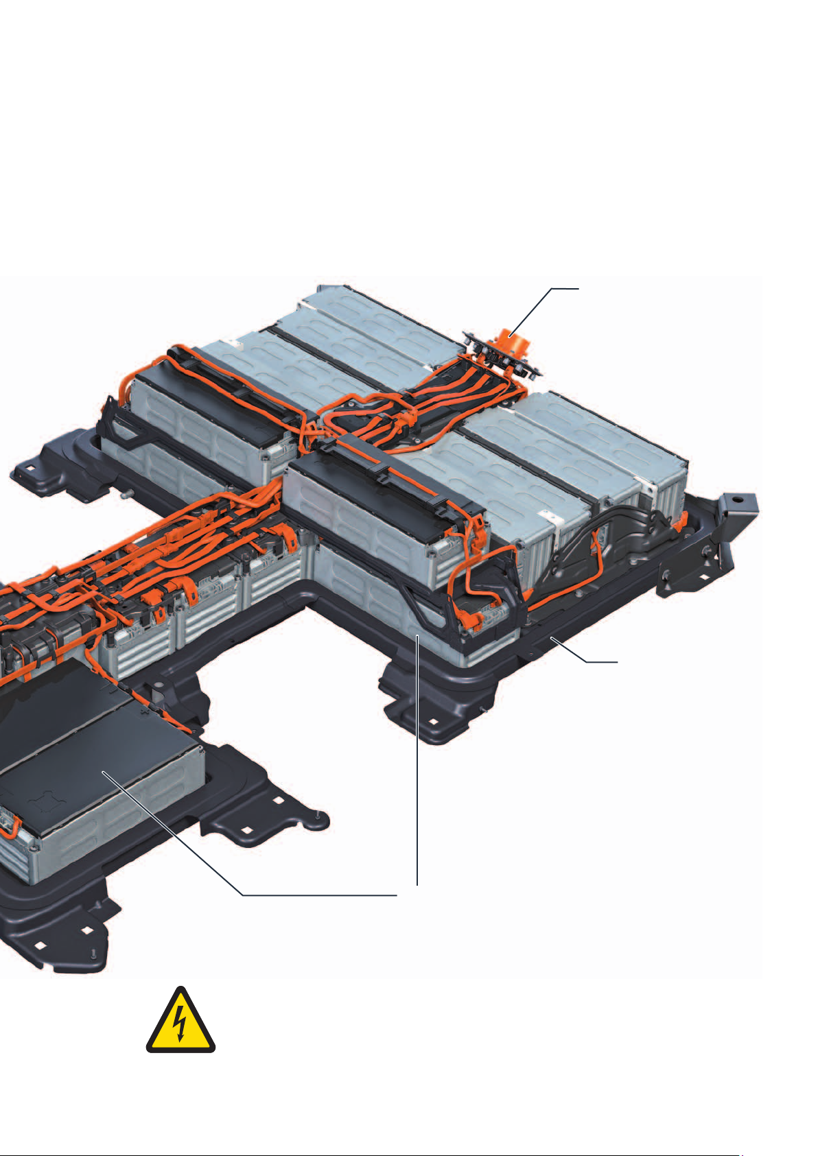
High-voltage battery 1 AX2
The high-voltage battery is installed under the vehicle and provides the energy needed for driving,
heating and cooling. Lithium-ion battery cells are used for storing the energy.
Technical data
Weight
Number of battery cells
Battery module
Nominal voltage
Nominal energy
Capacity
Temperature range
Switching unit for high-voltage battery SX6
with:
- Battery regulation control unit J840 and
- Module monitor control unit for batteries J497
344 kg
264 with 3.7 V
27
323 V
35,8 kWh
111 Ah
-25 °C to +55 °C
10 battery modules with 6 battery cells
as a slave modules
12 volt on-board power
system connection
High-voltage connection
24
Page 25
The battery regulation control unit J840, which has
been integrated into the switching unit for high-voltage
battery SX6, has the following functions:
Monitoring of the pilot line
Testing the crash signal
Master function for the module monitor control unit
for batteries J497
The module monitor control unit for batteries J497 has
the following functions:
Contactor controls
Regulating the charge level
Monitoring the isolation protection
Current measurements upstream and downstream
of the contactors
DC charging connection
for charging using DC current
Battery bottom part
m106_026
17 battery modules with
12 battery cells, subdivided into
8 master modules and
9 slave modules
Attention! Dangerous electric voltage!
Please note that maintenance work on the high-voltage battery may only be carried out by qualified
MAN high-voltage experts.
25
Page 26

HIgH-voltage system
Battery module
The eTGE has 27 battery modules connected in series.
8 master modules with 12 battery cells
9 slave modules with 12 battery cells
10 slave modules with six battery cells
The battery modules are comprised of the battery
cells. 3 battery cells configured in parallel are always
connected in series.
Master modules
Each master module can have up to 4 slave modules
connected to it. The master module controls the
charge level, and monitors the module temperature
and the cell voltage. The data are transmitted to the
module monitor control unit for batteries J497 using a
private data bus.
Battery cell configuration
(module with six battery cells)
Cell
m106_027
Master module with 12 battery cells
Slave modules
The slave modules register the cell voltage and temperature, and relay the data to the master module.
m106_028
Slave module with 12 battery cells
m106_029
26
Page 27

Charging unit 1 for high-voltage battery AX4
Charging unit 1 for high-voltage battery AX4 is responsible for converting the alternating current
sourced from the mains grid into direct current for charging the high-voltage battery 1 AX2. The
control unit for high-voltage battery charging unit J1050 has been integrated for control purposes.
A power distributor for the air-conditioning system has also been integrated.
Charging unit 1 for the high-voltage battery AX4 is housed in the motor compartment.
Fitting location
Charging unit 1 for high-voltage battery AX4 is housed
in the motor compartment on the right.
Technical data
Vehicle electrical system
connection for the control unit
Coolant Electrical
Air conditioner
compressor V470
High-voltage heater (PTC)
Z115
m106_054
Charging socket 1 for
high-voltage battery charging
UX4
High-voltage connector for
the power and control
electronics for electric drive
JX1
m106_030
Input alternating current voltage,
alternating current
Output direct current voltage, direct
current
Efficacy
Weight
100 – 400 V, 16 A/32A
220 - 450 V, 12 A
93 %
7.1 kg
27
Page 28

HIgH-voltage system
The charging connector
The charging socket 1 for high-voltage battery UX4 is the point connecting the vehicle with the
external source of power.
The charge plug includes the following contacts:
PP - Proximity
(max. rated current/wire cross-section)
CP - Control Pilot
(enable/cancel charging by the vehicle)
PLC – Power Line Communication
(communication with the charging station/charging
cable)
AC charge plug option
PLC
N CP PP L1
PE - Protected Earth
L1 - Phase 1
L2 - Phase 2
N - Neutral
+/-DC - DC current connection
DC charge plug option
PLC
CP PP
PE
PE L2
m106_031
High-voltage battery charging socket 1 UX4
Button module for battery charging EX32
m106_061
+/-DC
Charging indicator (LED)
Immediate charge button
Time-delay charge button
m106_032
28
Page 29

High-voltage wire routing
The following diagram provides an overview of how the high-voltage wires are routed to the highvoltage components.
Key
1
Three-phase current drive VX54
2 Power and control electronics for electric
drive JX1
3
4
5
Charging unit 1 for high-voltage battery AX4
High-voltage battery 1 AX2
High-voltage battery charging socket 1 UX4
3
DC 2 x 4 mm
6
2
DC 2 x 25 mm
7
6
7
Electrical air conditioner compressor V470
High-voltage heater (PTC) Z115
L1, L2
N
PE
AC 4 x 4 mm
DC 2 x 4 mm
2
2
2
AC
DC
5
2
AC 3 x 35 mm
4
DC 2 x 35 mm
2
2
1
m106_038
29
Page 30

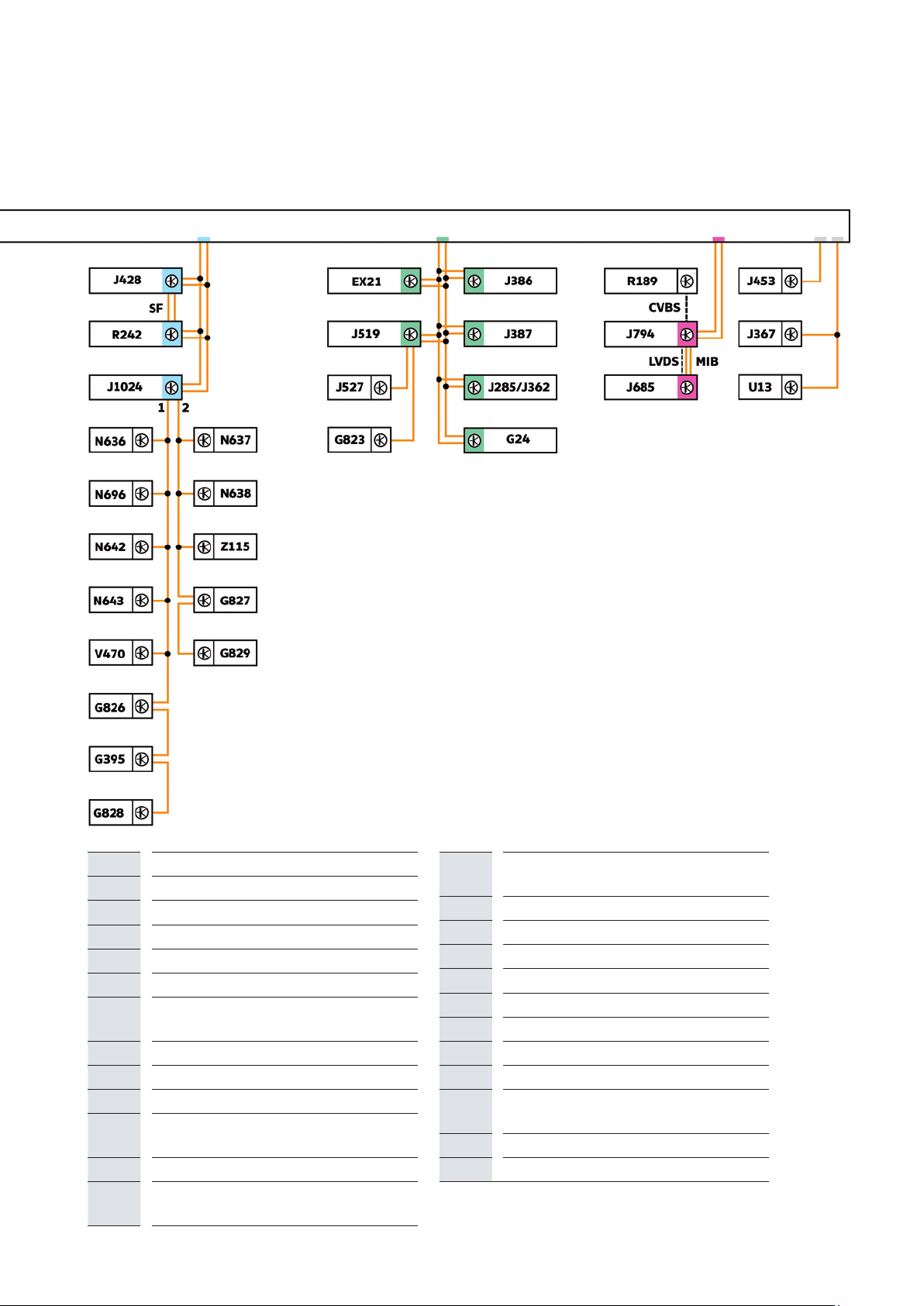
electrIcal system
Networking concept
The networking concept is based on that of the MQB
and has been expanded and adapted for the eTGE.
All CAN bus systems in the eTGE have a transfer
speed of 500kbit/s. The LIN buses have a speed of
19.2kbit/s.
The data bus diagnostic interface J533 contains the
control system for several LIN buses and forms the link
between the individual CAN buses as usual. Further
LIN buses are connected to various control units.
Due to the increased number of control units used for
the drive, the hybrid CAN bus is used in addition to the
powertrain CAN bus. This is a sub-bus (it is not connected to the data bus diagnostic interface J533) and
is used for communication between the individual
high-voltage components.
Key
Powertrain CAN bus
Hybrid CAN bus
Running gear CAN bus
CAN bus extended
Convenience CAN bus
Infotainment CAN bus
LIN bus
CAN bus line
LIN bus line
A
CVBS Colour Video Blanking Synchronisation
LVDS
MIB
SF
a
1
2
EX21
G24
G85
Diagnostic CAN bus
signal
Low voltage differential signalling
Modular infotainment matrix CAN bus
Sensor fusion CAN bus
Private CAN bus
LIN bus 1
LIN bus 2
Heater and air conditioning controls
Tachograph
Steering angle sender
G395 Refrigerant pressure and temperature
sender 1
G823
G826 Refrigerant pressure and temperature
G827 Refrigerant pressure and temperature
G828 Refrigerant pressure and temperature
G829 Refrigerant pressure and temperature
J104
J234
J285
J362
J367
J386
J387
J428
J446
J453
J497
Air humidity, rain and light sensor
sender 2
sender 3
sender 4
sender 5
ABS control unit
Airbag control unit
Control unit in dash panel insert
Immobiliser control unit
Battery monitor control unit
Driver door control unit
Front passenger door control unit
Adaptive cruise control unit
Parking aid control unit
Multifunction steering wheel control unit
Module monitor control unit for batteries
30
Page 31
m106_040
J500
J519
J527
J533
J587
J623
Power steering control unit
Onboard supply control unit
Steering column electronics control unit
Data bus diagnostic interface
Selector lever sensors control unit
Engine control unit
J685 Display unit for front information display
and operating unit control unit
J794
J840
J841
Control unit 1 for information electronics
Battery regulation control unit
Electric drive control unit
J966 Charge voltage control unit for high-
voltage battery
J1024
Thermal management control unit
J1050 Control unit for high-voltage battery
charging unit
Jxx*** Battery modules 0-26: J991 – J1002;
J1068; J1077 – J1085
N636
N637
N638
N642
N643
N696
R189
R242
Refrigerant expansion valve 1
Refrigerant expansion valve 2
Refrigerant expansion valve 3
Refrigerant shut-off valve 4
Refrigerant shut-off valve 5
Refrigerant shut-off valve 1
Reversing camera
Front camera for driver assist systems
U13 DC/AC converter with socket, 12 V -
230V
V470
Z115
Electrical air conditioner compressor
The high-voltage heater (PTC)
31
Page 32

electrIcal system
Fitting locations in the 12-volt vehicle electrical
system
Despite electrification of the drive and the integration of the high-voltage system this involves,
virtually all comfort components in the eTGE, except for the voltage supply, are supplied with
power by the 12-volt vehicle electrical system.
32
Vacuum pump V22 for brake booster in
the motor compartment on the right
Maintenance connector TW with instruction flag Fuse carrier SH on left in engine compartment
Page 33

In the dash panel
Relay carrier and fuse holder C
(SC) with onboard supply control unit J519
and instruction flag
Under driver seat, relay carrier
and fuse holder B (SB)
Battery under driver’s footwell Main fuses (SA) of the battery
m106_039
33
Page 34

electrIcal system
Maintenance plug TW
The maintenance connector TW is located in the motor
compartment and is marked with a warning sign. It is
on the one hand an electrical connection in the 12 volt
control circuit of the power contactors of the highvoltage battery, and on the other hand a component of
the safety line. If the maintenance connector TW is
opened, the safety line is opened and the 12 volt
control circuit of the contactors is interrupted. The
maintenance connector serves to disconnect the
voltage of the high-voltage system. Please use the
corresponding program in the vehicle diagnostic
systems for opening and disconnecting the highvoltage system proficiently. After opening, the
maintenance connector TW is secured against being
switched on again with the padlock T40262/1.
m106_055
Fuse carrier in the passenger compartment
The fuse for the voltage supply of the control current to
the contactors is marked with a warning sign.
m106_055
m106_057
34
m106_058
Page 35

Dash panel insert
The dash panel insert features the following e-specific
displays:
Power meter
Available power
Charge level of the high-voltage battery
Multifunction display (MFI) Current gear display
Power meter
The modified multifunction display (MFI) can display
the following additional information:
Constant display of the remaining range
Ready to drive with the display “READY”
Current power consumption
Average power consumption
Charging mode display
Speed
Available power Constant display
Charging mode display
Charge plug connected
Ready mode
of the remaining range
When charging is active, the indicator provides a
reading of the current charge level of the high-voltage
battery, and the charging station symbol flashes. The
driver door must be opened for this to occur.
m106_041
Charge state of the
high-voltage battery
m106_042
Remaining charge time Charging station symbol
35
Page 36

electrIcal system
Left-hand instrument dial
The left-hand instrument dial is comprised of the
Power meter
Power availability, and
Warning lamp for limited driving performance
The power meter (which displays the power output as
a percentage) shows the power demands. It is divided
into the categories power delivered, eco-friendly
driving, ready to drive, energy recovery, not ready to
drive and standby.
The “power availability” display shows the power
currently available.
If the indicator in the power availability instrument is
pointing to the red area, then there are considerable
restrictions to the drive power and comfort functions
are switched off. When this occurs, the warning lamp
for restricted vehicle performance (turtle) lights up in
the dash panel insert.
Energy recovery area/
energy recovery
(green section)
ready to drive
Power meter
Inactive state
Ready to drive/Ready
Not
Available power
Power delivered section
Eco-friendly driving
(blue section)
m106_043
Inactive state
When in standby mode, the indicators in both displays
point to the starting point of the scale, which is at the
lower left.
Warning lamp for restricted driving
performance
36
m106_044
Page 37

Ready mode
Availability of peak power
The ready-to-drive display is indicated both by
“READY” and by the indicator pointing to the
0position. In addition, an acoustic signal will sound
once. These displays appear when terminals S and 15
are active, and when terminal 50 is deactivated.
m106_045
If the indicator in the power availability instrument is in
the “max” section, then the maximum power is
available. The indicator in the power meter can deflect
up to 10 (= 100%) in the event of full load acceleration,
with the full power being available at all times.
The driving style determines how quickly the power
availability decreases in the white section.
Available power
m106_046
If the indicator in the power availability instrument is in
the “normal” section, then less than peak power is
available. The position of the indicator shows how
much power is available at most. The power meter
display (= power demanded) cannot exceed the
percentage currently shown by the power availability
instrument.
Display of the power availability
m106_047
37
Page 38

InfotaInment
MAN Media Van Advanced
MAN Media Van Advanced, a feature of the modular infotainment matrix (MIB), is installed as series
standard.
Touch-sensitive 8“ TFT colour display
Radio mode
Media mode
Telephone use
Voice operation
Rotary knob with push
button: on/off switch,
volume adjustment
Navigation mode
Traffic program function
Vehicle and system settings
Display of additional functions,
calls up set-up
m106_048
Rotary knob with push button:
menu settings, manual station settings,
SCAN function
MAN Media Van Advanced has been modified for use in an electric vehicle, and now features the
following additional functionalities:
e-specific displays, such as:
− Range monitor
− Energy flow display
− Energy recovery statistics
e-Manager
Note
You can find further information on the modular
infotainment matrix and the MAN Media Van Advanced in
MANGUIDE 101 “TGE basics”.
38
Page 39

The e-specific displays
m106_049
m106_050
Range monitor
The operating range display shows the current vehicle
range in a diagram. Furthermore, the driver is informed
about the potential (additional range) which can be
utilised when convenience functions are switched off.
This function is activated by the data bus diagnostic
interface J533.
Energy flow display
The energy flow display uses an animated diagram to
represent the flow of energy between the electric
motor and the high-voltage battery when accelerating
or braking.
The current being discharged is shown using a blue
arrow, and green arrows pointing in the opposite
direction show that the high-voltage battery is being
charged when braking or using energy recovery. The
high-voltage battery shown indicates the charge level.
m106_051
Energy recovery statistics
The energy recovery statistics show the amount of
energy recovered since the journey began. To show
this, the energy recovered each minute is displayed
using a column graph.
39
Page 40

InfotaInment
Der e-Manager
The user can use the e-Manager function to program vehicle charging and air conditioning in
relation to departure times and charging locations. The following diagram provides an overview of
the setting options:
e-Manager
Departure time
Setting options:
Programming up to 3 departure
times:
time, weekdays
Departure time 1 - 3
Setting options:
Entering a new charging location or
selecting a saved one.
Configuring charging locations:
air conditioning,
maximum charge current,
upper battery charge limit,
off-peak current.
Charging location
Basic setting
Electric driving/charging
settings
Setting options:
Immediate charging:
maximum charge current
e-Manager settings:
interior temperature, allow air
conditioning using the battery, lower
battery charge limit
m106_059
40
m106_062
Page 41

The maintenance intervals
Inspections are time-dependent and mileage-dependent. The first inspection takes place after
30,000 km or 24 months, followed by every 12 months or 30,000 km after that, depending on
which comes first. The production control number VI9 refers specifically to an electric vehicle.
The brake fluid inspection intervals remain the same: for the first time after 3 years, followed by
every 2 years.
servIce
Inspection and
additional work
Note
Please observe the most recent information in the service
literature.
30,000 km or
24 months
60,000 km or
36 months
90,000 km or
48 months
Towing
Electric vehicles feature a fixed connection between the drive wheels and the three-phase current
drive (electric drive motor). This connection cannot be undone without mechanical work. If the
vehicle needs to be towed, there are 2 options:
1. Towing the vehicle with the high-voltage system intact
120,000 km or
60 months
Switch the ignition (terminal 15) to “On” and move the selector lever to the N position to allow
electric freewheel mode. The vehicle can now be towed for a maximum distance of 50 km at
50km/h using a rope or tow-bar.
Using a bar for towing is recommended for safety reasons.
2. Towing with a damaged high-voltage system
If it is not possible to activate the high-voltage system, the vehicle must be transported with the
front axle raised. Freewheel mode cannot be activated, which creates a risk of overheating.
The corresponding text message in the dash panel insert reads: “Towing damages electrical
system”. Vehicle wallet.
41
Page 42

servIce
The emergency start function
If the high-voltage battery has been discharged completely, there is still an option allowing the
eTGE to be restarted twice for a short distance:
1. For approx. 100 metres, after switching the ignition off and on
2. For approx. 50 metres, after switching the ignition off and on once again
3. No more emergency starts are possible.
Note
Also observe the information in the vehicle wallet!
The charging plug emergency release
The charging plug is locked and unlocked by the
actuator for high-voltage charging plug lock 1 F498. If
unlocking is not possible, emergency unlocking can be
initiated by pressing and holding the immediate charge
button in the button module for battery charging EX32
and simultaneously pressing the opening button on the
remote control. If emergency unlocking is still not
possible, the charging plug can be emergency
unlocked via a Bowden cable. By pulling the
emergency unlocking loop of the Bowden cable, the
mechanism of the actuator for high-voltage charging
plug lock 1 F498 is actuated directly and the locking
pin in the charging socket is pulled back. Now the
charging plug can be removed. The emergency release
loop of the Bowden cable can be found at the bottom
in the passenger compartment, behind the driver‘s
seat.
Emergency release loop
behind driver‘s seat
42
Page 43

test your knowledge
Which answers are correct?
One or several of the given answers may be correct.
1. What particular measure has to be considered when renewing a shut-off or expansion
valve?
a) After installation, the new valve must be adapted using the diagnostic tester.
b) There are no specifics to be considered.
c) After installation, a waiting period of 30 minutes must be maintained before the heat pump
system can be put back into operation. During this period, the valve is automatically adapted
to the thermal management control unit.
2. What are the functions of the three-phase drive VX54 in the eTGE?
a) Drive motor and alternator for high-voltage battery
b) Starter for the electric drive motor
c) Monitoring of activation by the power and control electronics for electric drive
3. On an eTGE, what is interrupted when the maintenance connector for high-voltage
system TW is opened?
a) Positive supply to the battery regulation control unit J840 and the pilot line
b) Positive cable to the power and control electronics
c) Voltage supply to the charging unit 1 for high-voltage battery AX4
4. The coolant circuit in the eTGE ...
a) is also used to heat the vehicle interior.
b) is only required to cool the high-voltage components.
c) is required to ensure cooling of the high-voltage components as well as for re-evaporation of
the refrigerant in the heat exchanger.
d) has no dedicated water pump. Circulation is assured by the air conditioner compressor.
Answers:
1. a); 2. a); 3. a); 4. c)
43
Page 44

MAN Truck & Bus SE
Dachauer Straße 667
80976 München
www.mantruckandbus.com
MAN Truck & Bus – A company of the MAN group
 Loading...