

Page 1
MAN GUIDE 104
TGE - Driver Assist Systems
Page 2
New standards for driver assistance systems in the light commercial vehicle segment
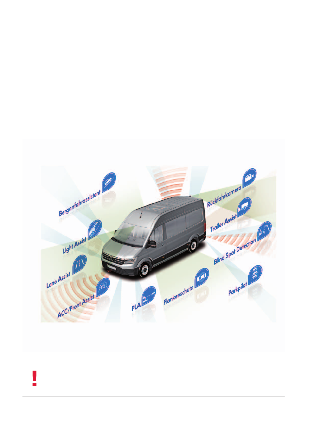
The TGE comes with a range of driver assistance systems truly innovative for this segment.
Thanks to the electromechanical steering system, parking and driving “in the lane” become much more comfortable. Each
customer can choose from a variety of optional driver assistance and safety systems to tailor the vehicle to his own needs. The
active edge protection sensors, which facilitate manoeuvring past obstacles, or the automatic distance control with “Follow to
Stop” function in conjunction with an automatic transmission – all these systems make their contribution to increased road
safety.
Note
The display contents shown in the displays correspond to the dashboard insert
resp. the display and operating unit of the Modular Infotainment Kit (MIB)
with German system setting and are only examples.
Technical status January 2018
2
m104_002
Page 3
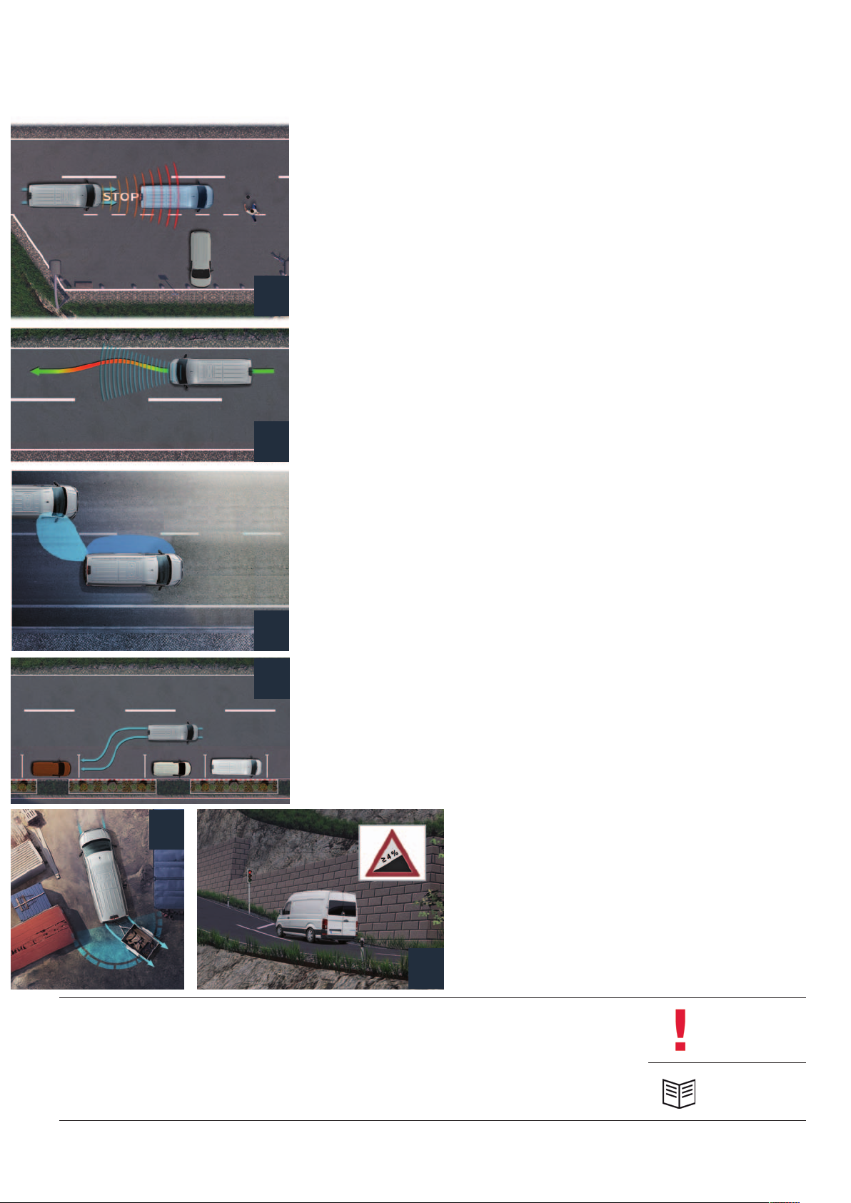
taBlE oF contEnts
4 ElEctromEchanical
PowEr stEEring
11 sPEEd control
drivEr assistancE systEms
12
12 distancE-rEgulating drivEr
assistancE systEms
19 Front camEra assistEd
19
drivEr assistancE systEms
37
26 Blind sPot sEnsor
31 Parking suPPort
drivEr assistancE systEms
26
37 rEar camEra assistEd
31
drivEr assistancE systEms
40 tyrE control systEms
42 othEr
drivEr assistancE
systEms
42
The MAN TGE Guide teaches the basics of design and function for sales and after-sales of new vehicle models, new
vehicle components or new technologies.
The MAN TGE Guide is not a sales manual nor a repair guide! Specified values are for the sake of easy understanding
only and refer to the data status valid at the time the MAN TGE Guide was created.
The contents are not updated.
Please use the appropriate technical literature for customer advice, maintenance and repair work.
Note
Reference
3
Page 4
ElEctromEchanical
PowEr stEEring
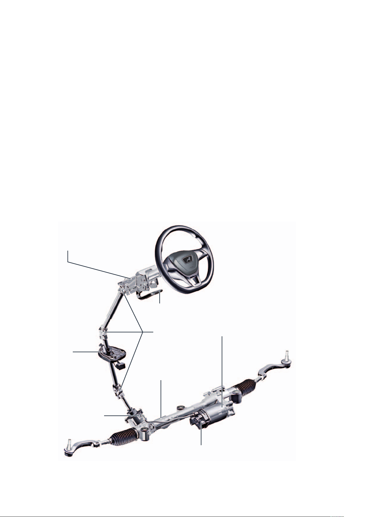
Electromechanical power steering with axially
parallel drive (APA)
Bosch APA steering
Two steering systems of different “sizes” are used in the TGE, depending on the front axle load. The difference
between the two steering systems is the torque output of the electric motor, which is a maximum of 6.3 Nm up to
1.8 t front axle load or 8.4 Nm from 1.8 t front axle load.
Power steering is provided as required depending on the vehicle speed, the steering torque applied by the driver,
the engine speed and the current steering angle.
Adjustment unit for longitudinal
and inclination adjustment
Support panel
Steering torque sensor G269
Locking lever
Universal joint
Steering gearbox
Motor for electromechanical
power steering V187
m104_003
Control unit for power steering J500
with steering angle sensor G85
(iLWS = internal steering angle sensor)
4
Page 5
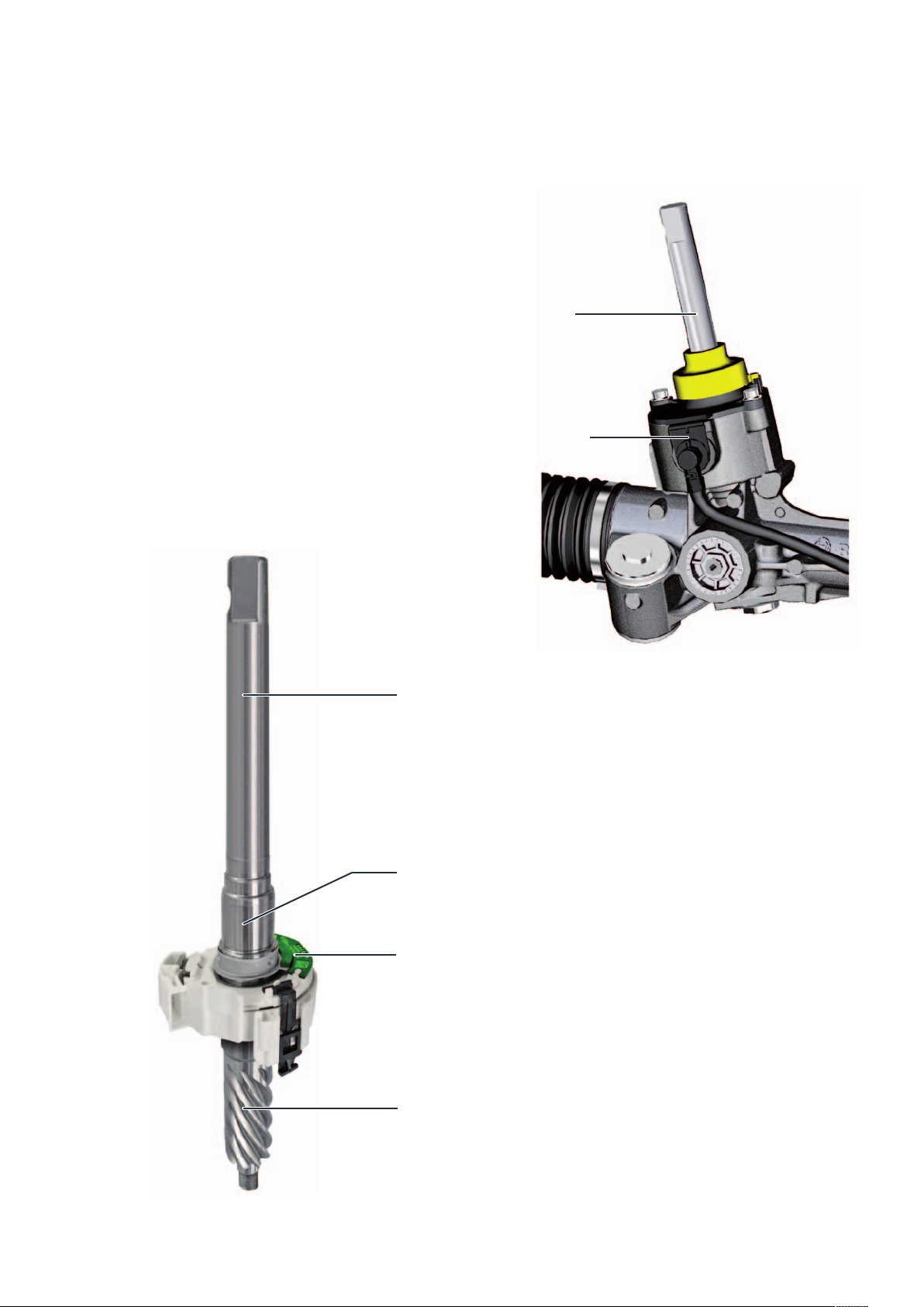
Steering torque sensor G269
The force applied by the driver during steering is
determined by the twisting of a torsion bar located
inside, between the steering pinion and the steering
input shaft. The relative rotation of the steering input
shaft relative to the steering pinion is measured. The
steering torque sensor (2 Hall sensors) determines how
far the torsion bar has been twisted. The signals are
passed on to the power steering control unit. The
steering force determined in this way serves as a basis
for calculating how much steering support still needs
to be applied for the current driving situation.
Steering input shaft
Steering torque sensor
Steering input shaft
Torsion bar (installed inside)
Steering torque sensor
m104_004
m104_005
Steering pinion
5
Page 6
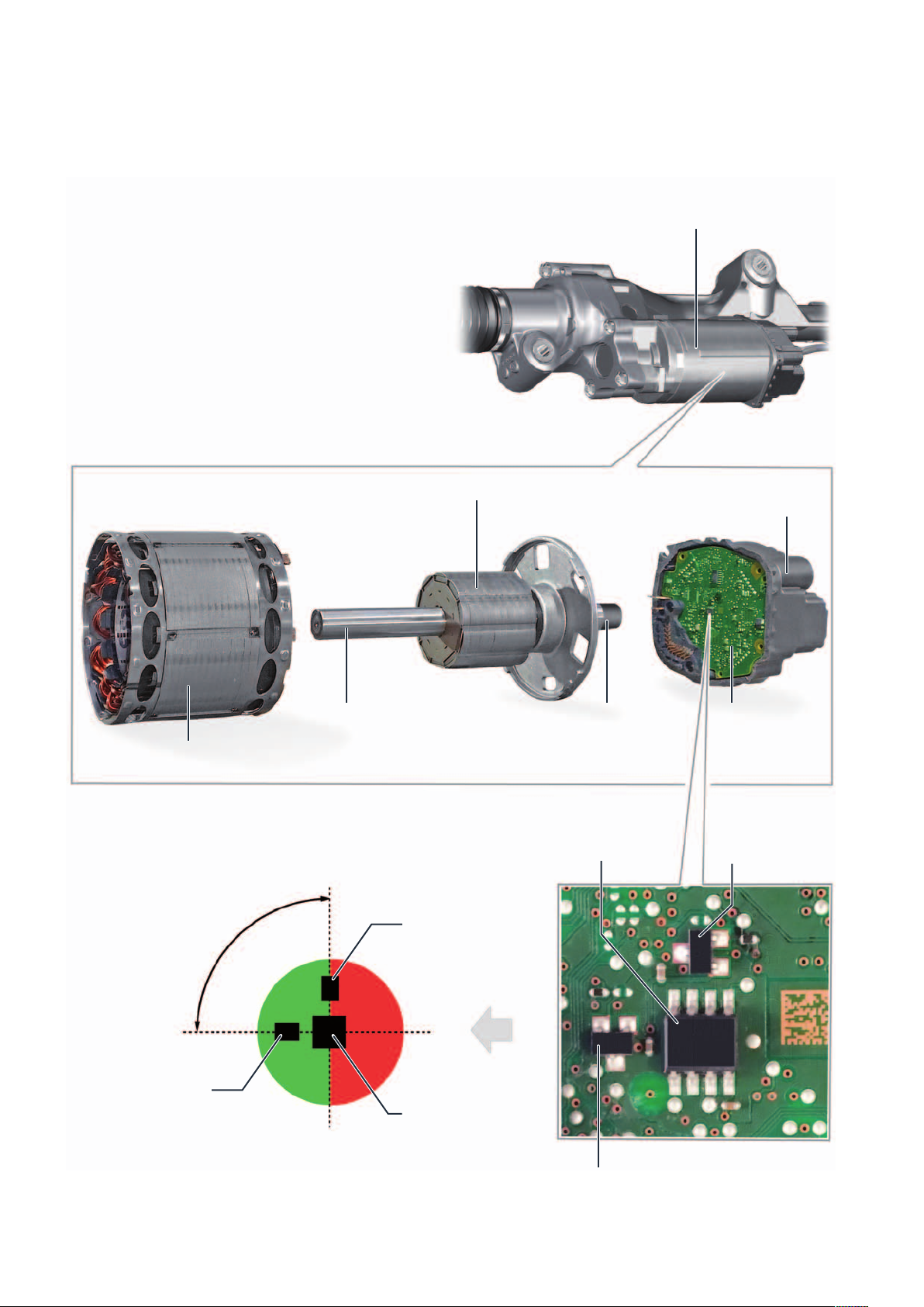
Internal steering angle sensor G85
The steering angle is calculated indirectly via motor
position, engine revolutions and a transmission factor
(steering input shaft to engine).
The motor position is determined by the AMR sensor
(anisotropic magnetoresistive sensor).
The AMR sensor detects the magnetic field of the
magnet located at the end of the motor shaft.
The engine revolutions are counted by 2 Hall sensors
and the position of the steering input shaft is determined by the index sensor.
Rotor
Motor for electromechanical power steering
V187 with integrated G85 steering angle sensor
End housing with
plug-in connections
m104_006
Stator
90° offset
Hall sensor 2
Motor shaft with magnet for
motor position sensing
Hall sensor 1
AMR sensor
Magnet
AMR sensor
PCB of the
control electronics
Hall sensor 1
Hall sensor 2
6
Page 7
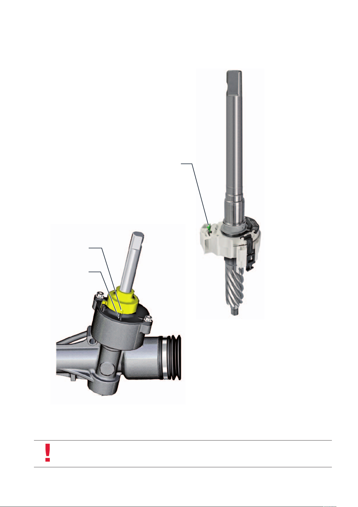
Index sensor
The index sensor indicates the position of the steering
centre.
Torsion bar (installed inside)
Mark on cap
Notch on
steering gearbox
m104_007
If the markings on the cap are aligned with the mark
on the steering gearbox, the steering is in its mechanical centre (steering centre position).
m104_008
Note
Please refer to the current repair guide in order to check the steering centre position!
7
Page 8
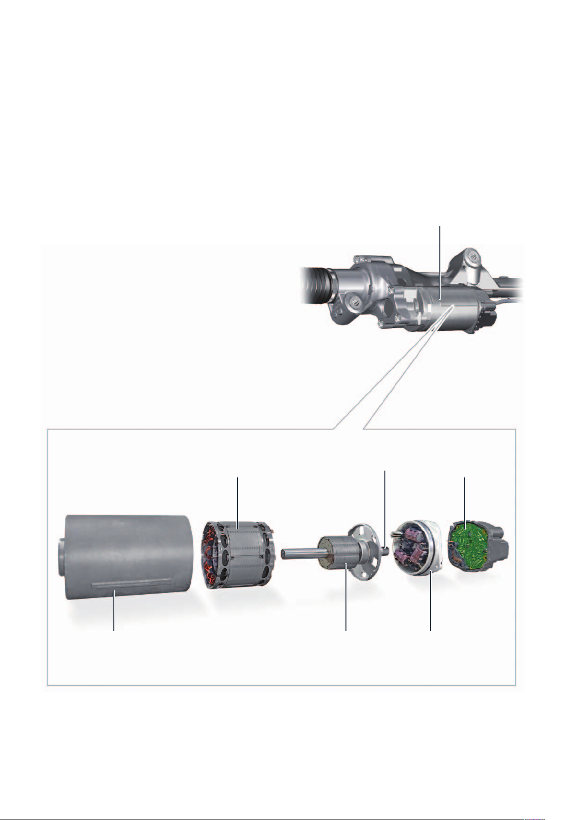
Motor for electromechanical power steering V187
The V187 electromechanical power steering motor is a 3-phase synchronous motor. It is equipped with a rotor with
a 10-pole ring magnet made of rare-earth magnets. Rare-earth magnets enable very high magnetic field strengths in conjunction
with the smallest possible structural dimensions.
The stator consists of 12 coils and plate packs, which
are interconnected to 3 phases in the motor. The
individual phases are energized one after the other so
that a moving magnetic field is generated from all
3 magnetic fields.
The rotor magnet adjusts itself according to the
direction of the rotating field generated by the coils like
a compass needle in the earth's magnetic field:
The speed and direction of rotation can be determined
by the current applied. No pre-excitation is necessary.
The rotor rotates synchronously with the field of the
stator current.
Motor for electromechanical power steering V187
Stator (12 coils and
plate pack)
Motor casing Rotor with 10-pole
annular magnet
Magnet
PCB of the
control electronics
Power electronics
and noise filter
m104_009
8
Page 9
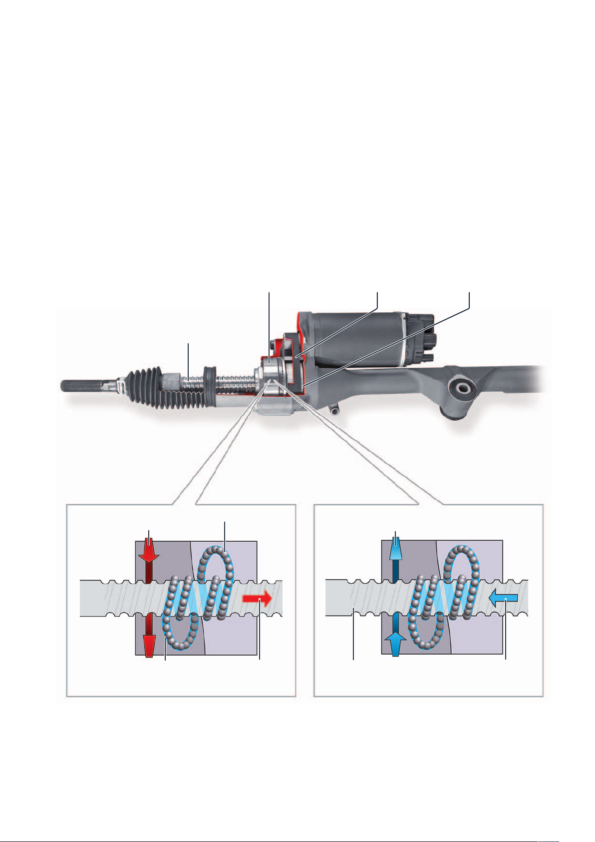
The motor for the electromechanical
power steering V187 is installed parallel
to the steering rack in the steering
housing. It develops a maximum torque
of 8.4 Nm to support the steering. The
steering support force generated by the
motor is transmitted via a toothed belt
to the ball screw gear.
The gear consists essentially of the
Spindle
recirculating ball nut, the balls and the
return channel.
The recirculating ball nut is firmly connected to the toothed wheel, which is
driven by the motor via the toothed belt.
The area of the spindle covered by the
nut and the return channel are filled with
balls. If a steering movement is performed, the recirculating ball nut rotates
Housing with integrated
recirculating ball nut
Toothed belt
and pushes the balls over the spindle.
The first ball in the spindle groove is
pushed into the return channel and the
first ball from the return channel
becomes the last ball in the spindle
roller (circulation system). Since the balls
and nut “move” in the same direction,
the spindle is now moved in the desired
steering direction.
Toothed wheel
Steering direction of the
vehicle to the left
Rotation of the
recirculating ball nut
Return channel
Ball
Longitudinal motion
of the steering rack
Rotation of the
recirculating ball nut
Spindle grooves
m104_010
Steering direction of the
vehicle to the right
Longitudinal motion
of the steering rack
Recirculating ball nut turned clockwise –
the steering rack moves to the right.
Recirculating ball nut turned counterclockwise –
the steering rack moves to the left.
9
Page 10

Functions
Directional stability correction Counter-steering assistance
When the vehicle pulls to the side and the driver has to
counter-steer for a short time (e. g. with constant
crosswind) or for a long time (e. g. with worn tyres), the
steering takes over the steering correction and applies
the required steering torque. This relieves the driver
and gives him the feeling that he or she no longer
needs to counter-steer that hard.
Active return
movement to return to the straight forward position.
The APA steering performs a self-check every time the
ignition is switched on – during this time the red control
lamp lights up.
In the event of system malfunctions, the indicator light
in the dashboard insert lights up in YELLOW or RED,
depending on the type of fault, and remains permanently on until the fault has been rectified. In addition,
the driver is informed acoustically of the fault. The
yellow control lamp signals a limited functionality of the
system. The red control lamp indicates that the system
functions are down.
This is a supplementary ESC safety function. In critical
situations, a steering recommendation for correct
counter-steering is given by a small steering torque.
Towing
If the vehicle must be towed, the steering can continue
to provide steering assistance even when the engine is
not running. The prerequisite for this is that terminal 15
is switched on, the speed is greater than 7 km/h and
the battery still supplies sufficient power.Assists the driver with a return torque after a steering
m104_011
Yellow for light warnings
e. g. short undervoltage
Red for serious malfunctions
With the use of this new electromechanical steering system, the following driver assistance systems can also be
installed:
Park assist steering
Trailer manoeuvring assist
Lane departure warning system
10
m104_012
Page 11
sPEEd control drivEr
assistancE systEms
The speed limiter
Task
The purpose of the speed limiter is to limit the speed of
the vehicle to a set maximum speed, even if the driver
requests a higher speed via the accelerator pedal. This
makes the compliance with prescribed speed limits
more comfortable.
System configuration
The prerequisite for the function of the speed limiter is
the installation of a cruise control system (GRA) or the
Adaptive Cruise Control (ACC).
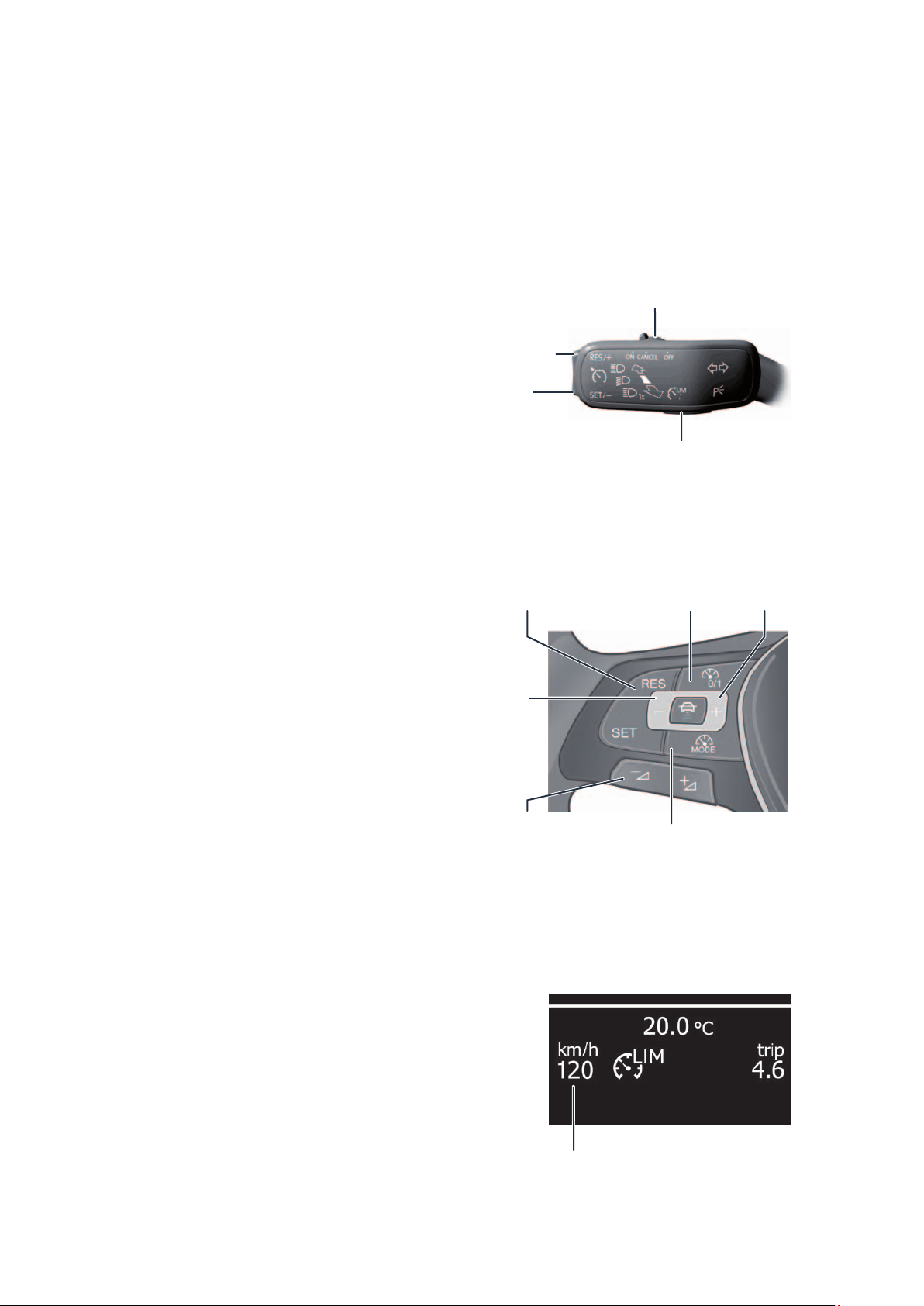
Function
RESUME button
Accelerate
SET button
Coast
Speed increase
+1 km/h
Speed reduction
-10 km/h
Switching GRA on and off/Cancel
Switching between
GRA and speed limiter
Switching
on and off
m104_013
Speed increase
+10 km/h
The function of the speed limiter is stored in the engine
control unit and is implemented by interventions in the
engine management system.
Kick-down operation of the accelerator briefly overrides the set speed limitation. Braking and clutching
does not cause the system to shut down. No automatic braking operations are performed.
An ignition change switches off the function.
Operation
Depending on the equipment of the vehicle, the function of the speed limiter is switched on or off and
operated using the left-hand steering column lever or
the buttons on the multifunction steering wheel.
Determining the
maximum speed and
speed reduction -1 km/h
Display of the set
maximum speed
Switching between
m104_014
GRA and speed limiter
m104_015
11
Page 12
distancE-rEgulating drivEr
assistancE systEms
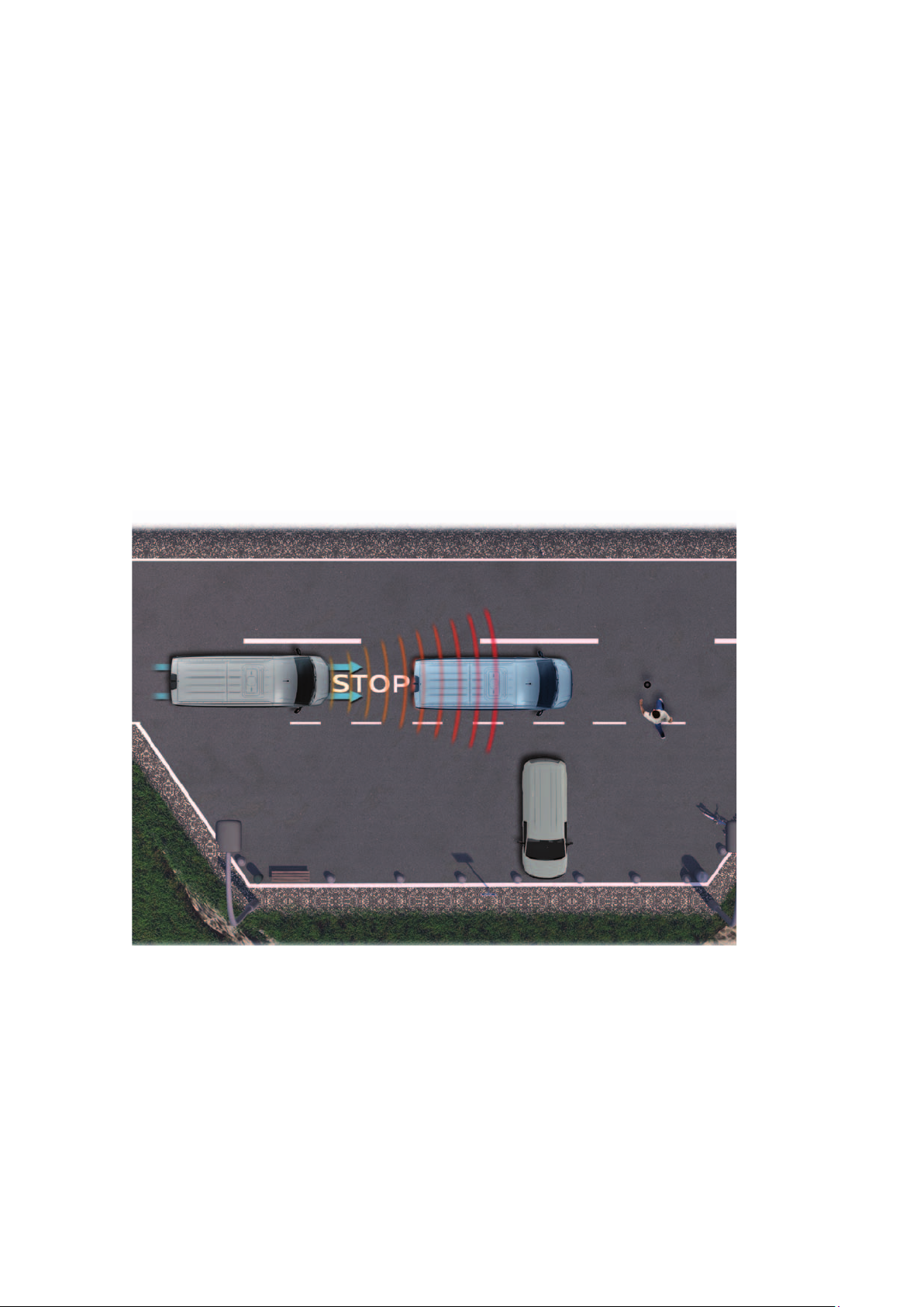
The environment monitoring system – Front Assist
Task
Within the system limits, the Front Assist
environment monitoring system helps to
avoid rear-end collisions or reduce the
consequences of accidents. The information from the front radar system is
used for this purpose. Front Assist
permanently monitors the traffic situation in front of the vehicle and reports
critical situations to the driver. Depending on the situation, it supports the
driver by braking independently and by
increasing the braking force applied by
the driver.
The system operates in a speed range of about 4 km/h to 160 km/h and a distance of up to about 120 meters.
The R242 front camera also provides information for the system to improve object positioning accuracy and
triggering reliability. This information is sent directly via a sensor fusion CAN to the J428 distance control unit.
12
m104_016
Page 13
Function
Monitoring: Front Assist permanently monitors the distance to the traffic ahead with the radar sensor installed in
the bumper below the license plate.
Prewarning: Front Assist detects collision hazards and assists the driver in critical situations by pre-conditioning
the braking system and giving visual and audible warnings with respect to a necessary driver response.
Automatic deceleration: If the driver brakes too weakly, Front Assist generates as much brake pressure as would
be necessary to avoid a collision. If the driver does not brake at all, Front Assist automatically decelerates.
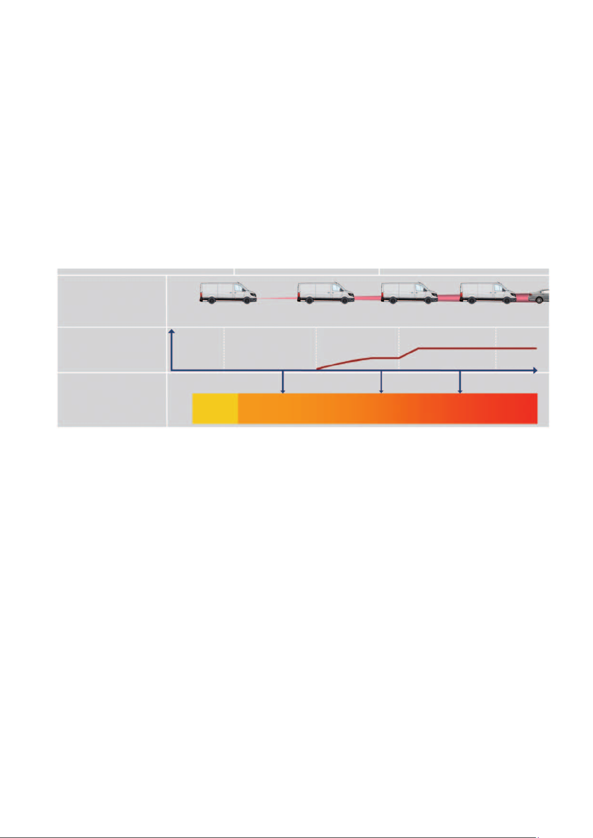
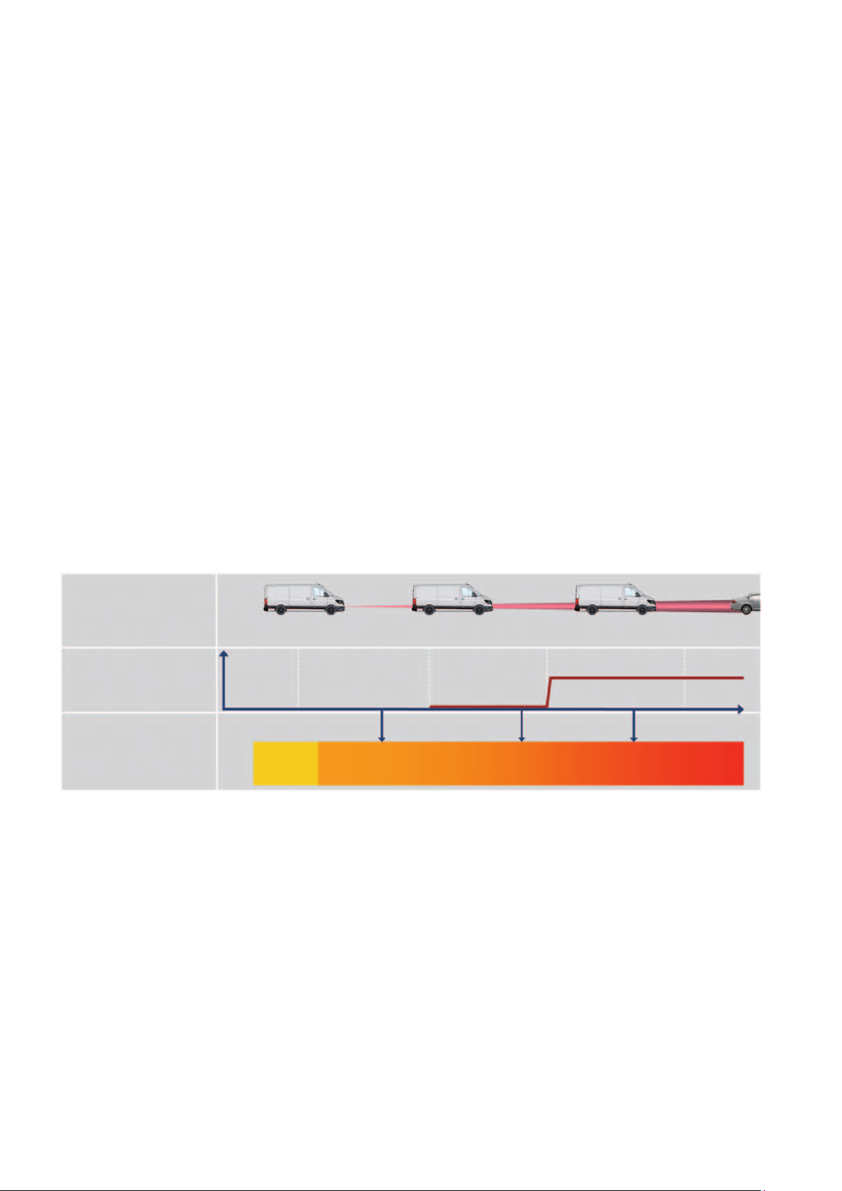
Sequence of a critical approach (Front Assist)
Risk of collision
slightly increased
increased
very high inevitable
optoacoustic warning
Driver doesn’t react
Driver brakes
Conditions
Stationary and moving vehicles
Speed range
4 - 160 km/h optical warning
> 30 km/h acoustic warning
30 - 85 km/h brake response to stationary objects
4 - 160 km/h brake response to moving and
stopping objects
1. Prewarning
Optical and acoustic warning
Prefill of the brake and the hydraulic brake
assistant (HBA) is set to increased sensitivity
in threshold switching
Prefill,
HBA switching
no
activity
APB pre-stage:
2
3.5 m/s
Driver brakes
targeted braking
(Brake pressure increases “as much as necessary”)
2. Main warning/automatic partial braking (APB)
Brake assistant threshold switching to
highest sensitivity
APB pre-stage deceleration with max. 3.5 m/s
3. APB main stage
Automatic deceleration at 6.0 - 8.0 m/s
4. Targeted braking
Intensification of the driver's braking to avoid a collision
or to reduce the consequences of an accident
Driver brakes
APB main stage:
6-8 m/s
2
Driver brakes
m104_017
2
2
13
Page 14
City emergency brake function
Task
The city emergency brake function is a system extension of the Front Assist and monitors the space in front of the
vehicle at speeds below 30 km/h.
Function
Monitoring: The city emergency brake function permanently monitors the distance to the traffic ahead.
Warning: An audible warning and the APB pre-stage is omitted.
Automatic deceleration: If an unavoidable collision is detected and the driver fails to react or does not react
sufficiently, the APB pre-stage is omitted. The system then initiates automatic emergency braking in the main stage
to achieve the maximum possible deceleration of 8,0 m/s
When the system intervenes, the instrument cluster shows an optical warning.
2
.
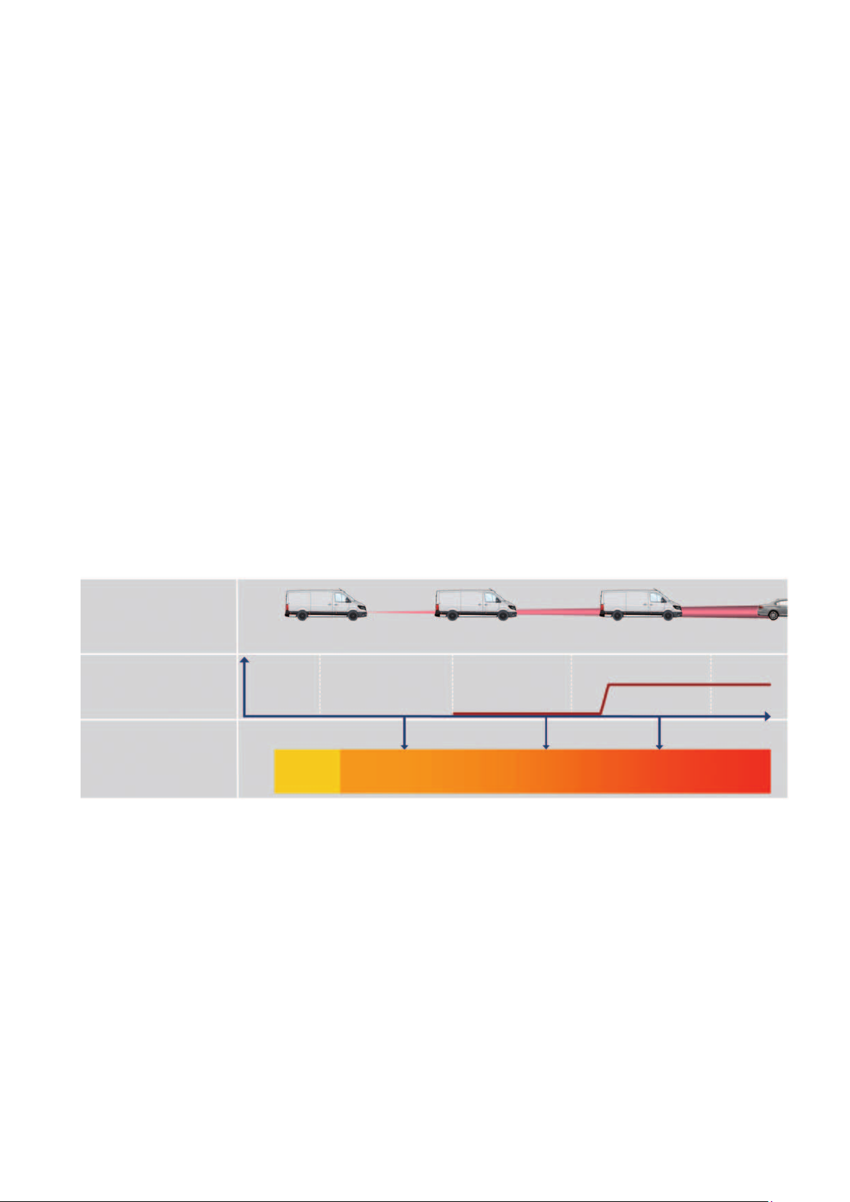
Sequence of a critical approach (city emergency brake function)
Risk of collision
slightly increased
Driver doesn’t react
Driver brakes
Conditions
Moving and stopping vehicles
Speed range less than 30 km/h
1. Prewarning
Prefill of the brake and the hydraulic brake
assistant (HBA) is set to highest sensitivity
in threshold switching
Prefill,
HBA switching
activity
no
increased
Driver brakes
targeted braking
(Brake pressure increases “as much as necessary”)
2. APB main stage
Automatic deceleration in the main stage with
3. Targeted braking
2
8,0 m/s
Intensification of the driver's braking to avoid a collision
or to reduce the consequences of an accident
Driver brakes
very high
APB main stage: 8 m/s
2
Driver brakes
m104_018
14
Page 15
Emergency brake function
Task
The emergency brake function monitors the traffic space in front of the vehicle within a speed range of
30 - 85 km/h. It can detect stationary and moving obstacles in this area and supports the driver in the event of a
collision.
Function
Monitoring: The emergency brake function permanently monitors the distance to the traffic ahead.
Prewarning: In case of slightly increased risk of collision there is a warning tone, an optical warning and the
HBA threshold switching (main stage) occurs.
Automatic deceleration: If an unavoidable collision is detected and the driver fails to react or does
not react sufficiently, the APB pre-stage is omitted. The system then initiates an
automatic emergency braking in the main stage in order to achieve the greatest possible deceleration of
6 - 8.0 m/s
2
.
Sequence of an emergency brake function
Risk of collision
slightly increased
Driver doesn’t react
Driver brakes
Conditions
Moving and stationary vehicles
Speed range 30 - 85 km/h
1. Prewarning
An optical and acoustic warning is given
Prefill of the brake and the hydraulic brake
assistant (HBA) is set to highest sensitivity
in threshold switching
Prefill,
HBA switching
activity
optoacoustic warning
no
increased
Driver brakes
targeted braking
(Brake pressure increases “as much as necessary”)
2. APB main stage
Automatic deceleration in the main stage at
6 - 8,0 m/s
3. Targeted braking
Intensification of the driver's braking to avoid a
collision or to reduce the consequences of an accident
Driver brakes
2
very high
APB main stage: 6 - 8 m/s
2
Driver brakes
m104_019
15
Page 16

Distance warning system
Task
The distance warning system visually
alerts the driver when he or she follows
a vehicle in front of him at a distance of
less than 0.9 seconds. The distance to
a vehicle in front should be such that
the following vehicle can be stopped
behind it without collision if the vehicle in
front suddenly brakes.
m104_020
Function
The distance warning system is active in
a speed range of 65 to 160 km/h and
deactivates itself at a speed of less than
60 km/h. This function uses the distance control unit to measure the
16
distance to the vehicle ahead. A table is
stored in the control unit software which
determines the critical distance as a
function of the speed. If a hazard is
detected due to tailgaiting, the
corresponding symbol in the dashboard
insert is switched on.
This warning can be switched on and
off via the MIB’s control and display
units.
Page 17

Adaptive cruise control (ACC)
up to 160 km/h
Task
The adaptive cruise control (ACC)
supports maintaining the speed and
distance to the vehicle in front by engine
and brake intervention within the system
limits. If there is no vehicle ahead, the
ACC works like a cruise control system.
If the radar sensor detects a vehicle in
front in its own lane, the ACC brakes if
necessary and regulates the preselected
following distance.With the ACC
function “Follow to Stop”, the TGE can
be automatically braked to a standstill if
the vehicle has an automatic transmission.
Radar sensor
The radar sensor in the current generation J428
distance control unit has been optimized in its antenna
power and evaluation of the input and output signals.
Obstacles can be identified easier and more accurately
by this.
Technical data
Mid range radar sensor with a frequency of 77 GHz
Detection range of the sensor 200 m
Note
The radar sensor must be recalibrated in the event of replacement or malfunctions. Please refer to the
current repair guide!
m104_022
Activatable > 30 km/h with manual transmission
> 4 km/h with automatic transmission
Speed range 4 km/h - 160 km/h
and 160 km/h - 0 km/h
m104_021
17
Page 18

System design and function
The distance control unit J428 is installed in the front bumper to detect the traffic situation in front of the vehicle. The
radar sensor and the control unit are one component. The sensor permanently records the distance and speed of the
vehicle ahead and transmits the data to the engine control unit, which now coordinates acceleration and braking. To
do this, it compares the values set by the driver with the actual status and takes corrective action if necessary.
The driver can use the multifunction steering wheel to activate and deactivate the system, set the desired speed and
set the following distance. In addition, he or she can define an ACC driving program (Normal, Comfort, Eco, Sport) in
the display and operating unit, which is to be active already when the vehicle starts.
The multifunction display of the dashboard insert displays all relevant system information, such as desired speed and
warning messages. If the vehicle is additionally equipped with a front camera (R242), the information from the camera
is also used to support the control of the ACC system. Object detection is sent directly to the distance control unit via
a sensor fusion CAN.
Front camera
Control unit for
distance control
Display in the display and
control unit
Multifunctional steering wheel
Multi-function display
in dashboard insert
18
m104_023
Page 19

Front camEra assistEd
drivEr assistancE systEms
The front camera
The R242 front camera for driver assistance systems is installed at the windscreen.
Task
The R242 front camera is a multifunction camera and
provides image information for the following driver
assistance systems:
Lane departure warning system (Lane Assist)
Traffic sign detection (Sign Assist)
High beam assistant HBA
Adaptive cruise control (ACC) with Front Assist
Function
The R242 front camera for driver assistance systems is
a black and white camera with an additional red light
filter for better contrast detection of lines and traffic
signs. It detects various objects, such as road markings, lighting (white/red light), vehicles and traffic signs.
An evaluation of the object recognition takes place
directly in the camera; this information is then sent to
the responsible control unit via the CAN Extended data
bus. This does not include the information for the
distance control unit. It receives the data directly via
the sensor fusion CAN. The visibility of the front
camera depends on the supporting systems. For the
high beam assistant the range of vision is about
1000m, all other supporting systems use a distance of
about 100m.
An additional heating foil is installed in the viewing area
of the camera in order to keep the viewing area “free”;
this is the screen heater for front sensors Z113.
When visibility is restricted, control is performed automatically by the camera.
Note
The R242 front camera must be recalibrated when changes are made to the vehicle, e. g. in case of:
Vehicle measurement with adjustment work, replacement or installation and removal of the windscreen.
Please refer to the current repair guide!
19
Page 20

Lane departure warning system (Lane Assist)
Task
The lane departure warning system “Lane Assist” helps
the driver to keep the vehicle in the lane by means of a
corrective steering intervention into the electromechanical steering system.
Function
The R242 front camera looks for lane markings or clear
lane boundaries in its field of detection. If a lane is
detected, a virtual lane is calculated from the real lane,
which is narrower than the actual lane.
The system tries to keep the vehicle in the virtual lane. Whenever the vehicle reaches the external
markings, the electromechanical power steering produces a corrective steering action.
m104_025
Special case of steering wheel vibration:
If the driver crosses the lane mark when the system is
active or changes lanes when the blind spot sensor is
installed with the indicator activated and there is a
vehicle in the detection range of the blind spot sensor,
he or she is alerted by a steering wheel vibration. In
addition, the prompt “Take over steering” is displayed
in the instrument cluster.
m104_028
Prerequisite for warning by steering wheel vibration:
The driver was not actively steering in the situation and the corrective steering intervention was not sufficient.
The driver can override the system at any time by steering intervention. The lane departure warning system can be switched on
and off via the instrument cluster or in the display and operating unit (MIB).
Active Passive
The system must be switched on
The speed is greater than 65 km/h
A lane is detected
The driver has his or her hands on the steering
wheel, determined by the steering torque sensor
Lane is not detected
Flashing indicator is activated
Speed is less than 60 km/h
Steering intervention of the driver without flashing
ESC switched off or in intervention
No hand on the steering wheel, determined by the
steering torque sensor
Curve radius too narrow
20
Page 21

The traffic sign recognition
Task
Traffic sign recognition provides the driver with information on current speed limits, overtaking prohibitions
including additional signs and cancellation signs.
m104_029
Function
The R242 front camera also detects traffic signs on the road. The system performs an internal plausibility check
with the navigation data, the current vehicle data and the recognized traffic signs.
If the data is evaluated positively, the recognized signs are displayed in the instrument cluster and/or in the radio/
navigation system. If the evaluation does not produce an unambiguous result, a traffic sign display is omitted.
If no traffic signs are detected, the data of the navigation system are used and displayed.
A speed warning can be activated in the display and control unit which reacts to the speed limits detected by the
camera, i. e. the driver is warned visually and/or acoustically if a set tolerance is exceeded. In addition, the speed
limit for vehicles with trailers can be adjusted. This allows you to set a valid speed limit for the country you are
travelling in and you will see the correct limits and speed warnings.
m104_030
21
Page 22

The high beam assistant – Light Assist
Task
The high beam assistant (HBA) enables the high beam to be switched on and off automatically depending on the
current driving situation.
Function
The high beam assistant detects vehicles ahead and oncoming vehicles with exterior lighting switched on as well
as sufficiently illuminated roads and high ambient brightness.
The high beam assistant can be used in combination with halogen and LED headlights.
The R242 front camera detects light objects in a range up to 1000 m for oncoming
vehicles and 400 m for vehicles ahead with an opening angle of 30° in the direction of travel
(15° to the left plus 15° to the right).
Maximum 1000 m
Detection area
m104_031
22
Page 23

Task
The oncoming vehicle is still outside the detection
range of the high beam assistant.
The oncoming vehicle is in the detection range of the
high beam assistant. But it is still far enough away so
that oncoming traffic is not dazzled yet. The high beam
assistant still keeps the high beam switched on.
m104_032
m104_033
The oncoming vehicle has approached so far that the
high beam assistant switches lo low beam, to avoid
dazzling the driver of the oncoming traffic.
The oncoming vehicle is no longer detected by the
highbeam assistant. The high beam is switched on
again.
m104_034
m104_035
23
Page 24

Switch-on and switch-off conditions
Function Switch-on conditions Switch-off conditions
Activation or
deactivation of the
high beam assistant
(HBA)
Function Switch-on conditions Switch-off conditions
Automatic activation or
deactivating the high beam by
the high beam assistant
(HBA)
Terminal 15 switched on
Automatic light selected
Push the main beam lever forwards
once
Error-free overall system
If all of the above conditions are met,
the MFA displays an icon to indicate
that the HBA is active.
Maintaining the
basic requirements
Low beam is switched on due to
detected darkness
Sufficient ambient darkness
Driving speed > 60 km/h
No vehicle/motorcycle ahead or
oncoming, or sufficiently
illuminated location in the
detection field of the camera
When the HBA high beam is active,
the high beam indicator light lights
up in the instrument cluster in addition
to the HBA icon.
Terminal 15 off
or
Switch not in automatic light position
or
Push the high beam lever forward to
switch to manual high beam
or
With high beam active: pull the high
beam lever backwards – this switches off
the high beam and also deactivates the
high beam assistant
If the high beam is switched on by the
high beam assistant, it is switched off again
under the following conditions:
Vehicle/motorcycle ahead or
oncoming or sufficiently illuminated
locality are detected
or
Vehicle speed drops below 30 km/h
or
The high beam assistant clearly
recognizes fog
or
Error in the partner control units
or
Limited view of the camera
24
HBA-ICON
Page 25

Networking
G823
E1
J527/E4
R242
J104
LIN
CAN comfort
CAN extended
CAN chassis
J519
Headlamp
J285
J533
MIB
J623
CAN drive
Legend
E1
Light switch
E4 Switch for manual low beam and
headlight flasher
G823 Sensor for humidity, rain and light
detection
J104
J285
J519
Control unit for ABS
Control unit in dashboard insert G81
On-board control unit
J527 Control unit for steering column
electronics
J533
J623
Diagnostic interface for data bus
Engine control unit
J685 Display unit for the controller of the display
and control unit, information, front
J794
Control unit for information electronics 1
R242 Front camera for driver assistance
systems
MIB
CAN infotainment
J794 J685
m104_037
CAN data bus line
LIN data bus line
Sensor cable
Actuator cable
CAN data bus modular infotainment kit
25
Page 26

Blind sPot sEnsor
Blind spot detection with assistant for reversing
out of parking spaces
Blind spot detection
Task
The “blind spot” sensor monitors the traffic space while driving in the blind angle on the driver and front passenger side and informs or warns the driver if dangers are detected. The system works with 2 control units for blind
spot detection (radar sensors) and the lateral ultrasound sensors installed in the rear of the vehicle.
Technical data and system limits
2 radar sensors (24 GHz)
4 laterally mounted ultrasound sensors
on the right and left side each
System active > 20 km/h
System passive < 15 km/h
The system remains activated when the ignition
status changes.
Note
Calibration of the radar sensors is not necessary. Please observe the current
repair guide!
26
m104_038
The system is deactivated in trailer operation.
The system is switched on or off in the multifunction
display or in the MIB.
Detection range of radar sensors approx. 20 m
behind the vehicle, angle of detection approx. 110°
Detection range of ultrasound sensors about 90 cm
Page 27

Function
If vehicles are within the detection range, the driver is informed or warned by the indicator lights in the door
mirrors.
m104_039
1 PDC ultrasound
sensor
3 PDC ultrasound sensors
1 radar sensor in the control units for
blind spot detection (left sensor shown)
on the left and right side each
Information about the control lamp
If a vehicle is in the detection zone, the control lamp on the detected side is switched on and lights up constantly.
Warning via the control lamp
If a lane change is detected during this information, either by actuating the indicator or by the R242 front camera
(lane departure warning system), a warning is given out. The indicator light starts flashing quickly.
An immediate warning without previous information is also possible if a lane change has already been initiated
and a vehicle enters the detection zone of the sensor from the rear. In vehicles with lane departure warning
system, a vibration and/or a short counteraction of the electromechanical steering may occur.
27
Page 28

Assistance system for reversing out of parking spaces
Task
Using the control units for blind spot
detection with integrated radar sensors
mounted behind the bumper, the
parking assistant monitors cross-traffic
behind the vehicle when reversing out of
a parking space or when manoeuvring.
Technical data and system limits
The detection angle of the radar sensors is about 110°.
The detection range is about 20 m.
The speed range of your own vehicle is between 0 km/h and 12 km/h.
The system has a follow-up time of about 10 seconds at standstill, for sound output as a warning.
The speed of the detected vehicle or object must be greater than 4 km/h.
Activation
System switched on in the multifunction display.
Reverse gear is engaged and the ABS sensors detect the reverse drive.
The parking assistance system Parking Distance Control (PDC) must be available and active.
This is particularly helpful in traffic
situations with poor visibility.
It warns of approaching vehicles/objects
when reversing and can reduce or even
prevent a collision by brake intervention
within its system limits. For this, the
radar sensors measure the distance and
speed of the crossing objects behind
the vehicle. The determined values are
then used to calculate the time until a
possible collision.
Deactivation
System switched off in the multifunction display.
Speed over 12 km/h when reversing.
A trailer is recognized.
Sensor view is limited.
All errors that generate an error entry in the PDC system.
Parking assistance system Parking Distance Control (PDC) not available or deactivated.
28
Page 29

Technical data and system limits
1. Information
m104_040
The measured distance from the vehicle itself to the approaching vehicle is sufficiently large or the calculated time
until a collision is higher than a time period stored in the control unit. If a collision is unlikely, the driver is visually
informed about the vehicle. The information takes place in the MIB.
2. Warning
The measured distance from the vehicle itself to the approaching vehicle or the calculated time until a collision is
less than a time period stored in the control unit. If the probability of a collision is increased, the driver is warned
by an acoustic system in addition to the optical information. The acoustic warning is given by the sound generator
of the parking assistant.
3. Intervention
The measured distance from the vehicle itself to the approaching vehicle is small enough or the calculated time
until a collision is less than a time period stored in the control unit. Thus, a collision is imminent. The system
causes emergency braking to a standstill in order to avoid, in the best case, a collision or to mitigate a collision.
29
Page 30

Technical data and system limits
Legend
m104_041
E266
G44
G45
G46
G47
G397
G568
G569
G716
G717
Pushbutton for parking assistant
Speed sensor, rear right
Speed sensor, front right
Speed sensor, rear left
Speed sensor, front left
Sensor for rain and light detection
Encoder for front left park steering assistant
Encoder for front right park steering assistant
Encoder for rear left park steering assistant
Encoder for rear right park steering assistant
G956 Encoder 2 for front right parking assistant
G957
G958
G959
H3
H15
H22
J104
J285
J345
J446
J500
J519
J527
Encoder 2 for front left parking assistant
Encoder 2 for rear right parking assistant
Encoder 2 for rear left parking assistant
Buzzer and bell
Warning buzzer for rear parking assistant
Warning buzzer for front parking assistant
Control unit for ABS
Control unit in dashboard insert
Control unit for trailer recognition
Control unit for parking assistant
Power steering control unit
On-board control unit
Control unit for steering column electronics
J533
Diagnostic interface for data bus
J685 Display unit for the controller of the display
and control unit, information, front
J794
Control unit for information electronics 1
J1086 Control unit for blind spot detection
(master control unit)
J1087 Control unit 2 for blind spot detection
(slave control unit)
K303 Warning light for blind spot detection in the
left door mirror
K304 Warning light for blind spot detection in the
right door mirror
R242
Front camera for driver assistance systems
CAN data bus line
Discreet line
Sensor cable
CAN data bus chassis
CAN data bus comfort
CAN data bus infotainment
CAN data bus extended
MIB
CAN data bus modular infotainment kit
Private CAN (Private CAN data bus
blind spot detection)
30
Page 31

Parking-suPPorting drivEr
assistancE systEms
Task
Parking distance control is designed to warn the driver of obstacles in the front and rear areas
when entering and exiting the parking space and when manoeuvring. The acoustic warning is
given out via the front or rear sound generators.
The system consists of:
4 PDC ultrasound sensors at the front
4 PDC ultrasound sensors at the rear
1 push button
2 sound generators
1 parking assistant control unit
Radio or MIB (optional)
G252 G206
G253 G205
G254 G204
G255 G203
J446
E266
Detection ranges of the sensors:
front centre: about 120 cm
front lateral: about 60 cm
rear centre: about 160 cm
rear lateral: about 60 cm
F41
H15
H22
Legend
E266
F41
G203
G204 Encoder for parking assistant, rear centre
G205 Encoder for parking assistant, rear centre
G206
G252
The system is activated via push-button E266, by engaging reverse gear and via detection of the status “vehicle is rolling backwards”.
If the sensors detect an obstacle in the front area while driving at a speed of up to 15 km/h, a message on the MIB/radio is
displayed when the vehicle is at a distance of about 95 cm from the obstacle, and the front sound generator is switched on
when the vehicle is at a distance of about 45 cm from the obstacle.
If the trailer recognition control unit J345 detects a trailer, the rear sensors are switched off.
Pushbutton for parking assistant
Reversing switch
Encoder for parking assistant, rear left
left
right
Encoder for parking assistant, rear right
Encoder for parking assistant, front right
G253 Encoder for parking assistant, front centre
right
G254 Encoder for parking assistant, front centre
left
G255
H15
H22
J446
Encoder for parking assistant, front left
Warning buzzer for rear parking assistant
Warning buzzer for front parking assistant
Control unit for parking assistant
m104_042
31
Page 32

Optical parking system with edge protection (OPS)
The optical parking system with edge
protection is an extension of the parking
distance control system. For vehicles
with OPS, also the vehicle sides are
actively monitored.
The OPS with edge protection uses a 16-channel
system consisting of:
4 PDC ultrasound sensors, front
4 PDC ultrasound sensors, rear
4 PDC ultrasound sensors, left side of vehicle
4 PDC ultrasound sensors, right side of vehicle
1 MIB
1 parking assistant control unit
1 push button
2 beepers
The 16-channel OPS also covers the
vehicle edges and thus extends the
detection range of the system to 360°
around the vehicle. The sectors of the
edges can be activated individually.
When a door is opened, the lateral
sectors are immediately deactivated.
The monitoring area is divided into
4sectors at the front and rear, with the
middle sensors covering a larger area
than the outer sensors.
After all doors are closed again, the
lateral sectors are not displayed again
until the vehicle has driven a defined
distance or an obstacle has been
reliably detected in the side area. The
vehicle path shows the range in which
the vehicle moves based on the steering
The lateral detection zones are also
divided into 4 sectors, all having the
same detection range.
Detection ranges of the sensors:
front centre: about 120 cm
front lateral: about 90 cm
rear centre: about 160 cm
rear lateral: about 90 cm
right / left: about 90 cm
angle and speed data. Detected obstacles are displayed depending on the
distance in colour in the respective
sector. In addition, with red segments a
permanent tone is given out, while an
interval tone is emitted for yellow segments.
32
m104_043
Position of PDC ultrasound sensors
for edge protection
Page 33

The system is activated via push-button E266, by
engaging reverse gear and via detection of the status
“vehicle is rolling backwards”. When activated, there is
also a display in the MIB.
Push button for parking assistant E266
m104_044
m104_045 m104_046
Vehicle path, either at the front or
during forward movement
Legend
Obstacle detected no danger
Obstacle detected, but still “far away”. Risk of collision
Obstacle detected, but already “close” to it Increased risk of collision
If the control unit for trailer recognition J345 detects a
trailer, this is shown in the display; the sensors at the
rear and on the sides are switched off.
Vehicle path, either at the rear or
during backward movement
m104_047
33
Page 34

The park steering assistant - Park Assist (PLA 3.0)
Task
Thanks to the electromechanical steering, the park steering assistant could be implemented into the TGE.
The system is able to enter and leave longitudinal parking spaces in multiple moves.
Operation
Press the park steering assistant button E581 to
activate the park steering assistant. Activation is
indicated by the indicator light in the switch; the multifunction display simultaneously shows an indication.
Park steering assistant button E581
m104_048
Parking space measurement
The automatic parking space search takes place
permanently on both sides of the vehicle up to a
maximum speed of 40 km/h. If the driver presses
button E581 and additionally sets the indicator to the
desired parking direction (right or left), the suitable
parking spaces are displayed in the multifunction
display on the desired side while passing. A parking
space with a length of “vehicle length plus 150 170cm” is required for parking. Passing must be
done at a distance of 50 cm to 200 cm so that the
parking space can be measured.
If the park steering assistant has not been activated
via the button, the multifunction display does not display suitable parking spaces. However, the driver can still activate the
system after passing a parking space. If a suitable parking space has been detected and the distance after that space is still not
too far, the park steering assistant can still move into the previously detected parking space.
m104_049
34
Page 35

Parking
The front park steering assistant sensors measure up to 450 cm into the depth. This also covers the distance to lateral obstacles
at the edge of the parking space, so that L3 and L4 vehicles can be parked up to approximately 50 cm and L5 vehicles up to
approximately 60 cm away from the obstacle.
The system takes over the steering during the parking process and is able to park in multiple moves. The driver stays in control
of accelerator, brake and clutch. Instructions on the display must be followed, such as “Apply brake!”
Vehicle lengths
L3 wheelbase 3640 mm + overhang 1346 mm
L4 wheelbase 4490 mm + overhang 1346 mm
L5 wheelbase 4490 mm + overhang 1901 mm
m104_050
If there is an obstacle on the opposite side of the detected parking space, the parking process cannot be carried out. Otherwise
there is a risk of touching the obstacle even though the parking space is large enough.
After the vehicle has been stopped, the message “Parking not possible, opposite side blocked” appears in the multifunction
display. The Park Assist function is terminated.
35
Page 36

Exiting
To initiate an exiting process, button E581 must be pressed and the indicator must be set in the desired exiting direction. The
PDC ultrasound sensors determine the distance in front of and behind the vehicle. It must have at least a total size of 100 cm.
The park steering assistant performs the steering movements necessary for exiting. The display of the dashboard insert shows
instructions to be observed, e. g. “Apply brake” to the driver.
Abort function when entering and leaving parking spaces
Steering intervention by the driver
Switching off the PLA by pressing button E581
Speed too high (more than 7 km/h) when parking – 1 x brake jerk
Risk of collision with an obstacle – Braking to standstill
m104_051
36
Page 37

rEar camEra assistEd
drivEr assistancE systEms
The reversing camera
The R189 reversing camera supplies a video image to
the control unit for information electronics 1 J794.
This sends the video image to the display unit for the
controller of the display and control unit, front, J685.
Static guiding lines are also displayed.
The camera is located in the housing of the raised
brake light and screwed into it.
m104_052
Legend
J533
J685 Display unit for the controller of the display
J794
R189
FBAS
Video image – rear view camera
in display (MIB)
Diagnostic interface for data bus
and control unit, information, front
Control unit for information electronics 1
Reversing camera
Colour image blanking synchronization signal
Static guiding lines for the vehicle width
m104_054
MIB
m104_053
CAN data bus infotainment
CAN data bus line
LVDS (low voltage differential signalling)
CAN data bus modular infotainment kit
Auxiliary markings for the
vehicle distance:
2 m
1 m
0,4 m
Note
Calibration of the rear view camera is not required. Please observe the current repair guide!
37
Page 38

Trailer manoeuvring assistance – Trailer Assist
Task
Trailer Assist supports the driver when reversing with a
trailer. The driver preselects a direction to drive to and
the position of the trailer (buckling angle). The system
now steers towards the pre-selected direction, so that
the driver only needs to control the speed of the
vehicle.
The Trailer Assist function is integrated in the parking
assistant control unit as a software module. The
camera itself is housed in the carrier of the license
plate light and supplies the required data, such as the
position of the trailer (buckling angle), to the control
unit of the parking assistant J446.
System configuration
Camera in the carrier of
the license plate light
m104_055
m104_056
Legend
E43
E581
J104
J217
J285
J345
J386
J446
J500
38
Switch for mirror adjustment
Park steering assistant button
Control unit for ABS
Control unit for automatic transmission
Control unit in dashboard insert
Control unit for trailer recognition
Control unit for driver's side door
Control unit for parking assistant
Power steering control unit
J519
J533
R368
m104_057
On-board control unit
Diagnostic interface for data bus
Camera for trailer manoeuvring assistant
CAN data bus drive
CAN data bus chassis
CAN data bus comfort
CAN data bus infotainment
CAN data bus line
Discreet line
Page 39

Task
The engine is running
The ESC must be switched on
The reverse gear is engaged
The trailer must be electrically connected
The system is activated via the
park steering assistant button
During the manoeuvring process, the driver controls
the mirror adjustment switch as well as the accelerator,
brake and clutch pedals.
Steering intervention is automatic.
The switch for mirror adjustment determines the
direction in which the trailer is to be moved. If the trailer
is to be pushed to the right, the switch for mirror
adjustment is set to the right. The steering angle is
now determined on the basis of the target/actual
position, taking into account the maximum permissible
buckling angle. By pressing the switch for mirror
adjustment, the driver can correct his or her selected
manoeuvring direction at any time.
It is also possible to lock the trailer, e. g. to move it
“straight backwards”. This is done by “pushing back”
the switch for mirror adjustment. If it is necessary to
make a forward correction when the trailer is locked,
you can stop, drive forward and then continue in
manoeuvring mode without interrupting the function.
m104_058
m104_059
The display of the instrument cluster shows an image
of the target and actual position of the trailer. The
detection of the position (buckling angle) of the trailer
isprovided by the trailer manoeuvring camera. The
maximum permissible buckling angle is determined
under consideration of the trailer drawbar.
At a speed of more than 7 km/h, Trailer Assist reacts
by aborting the function or by automatic brake intervention, until standstill if necessary.
Target
position
Maximum
buckling angle
m104_060
Actual
position
m104_061
Released
buckling angle
39
Page 40

tyrE control systEms
Task
T
yre pressure monitoring is used to monitor tyre inflation pressures. Deviations from the target pressure are measured with tyre
pressure sensors installed in the wheels and displayed in various warning messages. The display is in the multifunction display
and/or in the display and control unit of the MIB.
System configuration
Legend
G222-
G225
J285
J502
J533
J685 Display unit for the controller of the display
J794
R175
Function
At cyclic intervals, once every 30 s, the
tyre pressure sensors send RF telegrams to the tyre pressure control unit
J502. The ID of the sensor, the direction
of rotation and the current tyre pressure
are transmitted among other things. The
data is sent while the vehicle is moving
and also when the vehicle is stationary.
Tyre pressure sensors
Control unit in dashboard insert
Tyre pressure control unit
Diagnostic interface for data bus
and control unit, information, front
Control unit for information electronics 1
Antenna for tyre pressure control
This information is received by the
antenna built into the control unit for
tyre pressure monitoring J502. The
wheel management in the control unit
evaluates the HF telegrams after driving
start. Together with the HF level evaluation, the sensors are assigned the
correct installation position on the
MIB
m104_062
CAN data bus extended
CAN data bus comfort
CAN data bus infotainment
CAN data bus line
LVDS (low voltage differential signalling)
CAN data bus modular infotainment kit
vehicle. If the spare wheel also has a
tyre pressure sensor, this is not taken
into account as long as the wheel is not
used in a rotating 5-wheel system. New
tyre pressure sensors are automatically
taught-in during driving mode within
max. 10 minutes after driving start.
40
Page 41

Tyre pressure sensors G222 - G225
The tyre pressure sensors G222 - G225 are screwed
to the tyre valves. The measured tyre pressure values
are transmitted by HF telegrams to the tyre pressure
control unit J502.
With a rapid pressure loss > 0.2 bar/min, the tyre
pressure sensor transmits in a faster transmission
cycle. The “active phase” of the sensor ends after
5minutes of vehicle standstill.
m104_063
If the tyre inflation pressure drops to < 1.4 bar during the passive phase, the data telegram is transmitted during the first wheel
revolution or even when the vehicle is stationary, thus providing the warning in the multifunction display and in the display unit for
the controller of the display and control unit (MIB). If the instrument is a basic instrument cluster, the warning appears as a
scrolling text. In addition, a chime sounds and the control lamp of the tyre pressure monitoring is switched on.
m104_064
There are three warning levels:
Check tyre pressures! 0.3 bar under set filling pressure
Tyre pressures are too low! 0.5 bar under set filling pressure or acc. to EU directive at
the latest at 20% below the filling pressure for hot tyres
Puncture! The actual filling pressure is less than 1.5 bar.
m104_065 m104_066
41
Page 42

othEr drivEr assistancE
systEms
Fatigue detection
Task
The fatigue detection function is a comfort function that provides support and prevention by evaluating the steering behaviour to
detect the driver's state of fatigue and, if necessary, by issuing a warning message in the multifunction display as well as an
acoustic warning to prompt him to take a break.
Function
Fatigue detection can be activated or
deactivated via the operating and
display unit of the MIB. The system is
ready after “Terminal 15 switched on”; a
5-minute learning process starts when
driving in the fatigue detection speed
range between 60 - 200 km/h. There is
no break recommendation during this
Fatigue detection activated Break recommendation
time. Only the steering behaviour is
taught during the teach-in phase. In
addition to the steering behaviour,
driving situation data (e. g. vehicle
speed, accelerator pedal actuation,
flashing, time of day, driving time) and
the driver's operating activity on the
setting and comfort elements (e. g. air
conditioning, telephone operation) are
recorded for the display of the pause
recommendation.
This information is sent to the diagnostic
interface for the data bus via CAN
messages and evaluated there. The
fatigue detection function is integrated
in the diagnostic interface for data bus.
m104_067
m104_068
If the system detects that the driver is tired, a pause recommendation is given by an optical and an acoustic signal. A text
prompt for a pause is displayed in the multifunction display of the dashboard insert for 5 seconds, and a chime sounds. This
message is repeated once after 15 minutes.
42
Page 43

The multi-collision brake
Task
Many accidents are multi-collisions, i. e. multiple collisions in which further collisions with side boundaries or oncoming traffic
occur after the first impact. Brake interventions shall prevent subsequent collisions or reduce the impact energy of a subsequent
collision.
Function
The multi-collision brake triggers
automatic brake engagement when the
first collision is detected.
This automatic braking is intended to
prevent, or at least reduce, the impact
energy of a subsequent collision.
The multi-collision brake decelerates the
vehicle with of 6 m/s
and simultaneously activates the
emergency brake light and the hazard
warning lights.
2
as a maximum
The ESP lamp in the dashboard insert
informs the driver about the brake
intervention. Generally, the multi-collision
brake brakes down to a vehicle speed
of 10 km/h. Thus, the vehicle can
remain controllable by the driver even
after a collision, depending on the
accident situation. The air bag control
unit sends a corresponding message to
the brake control unit in order to trigger
the multi-collision brake.
m104_069
The multi-collision brake is activated
exclusively by the sensors of the
air bag control unit.
The driver can override the multi-collision brake at any time. If the driver
accelerates or applies full braking with
higher deceleration, the system is
overridden.
43
Page 44

The hill start and descent assistant
The hill start and descent assistant are comfort systems designed to make driving uphill and downhill easier for the driver.
Thefunctions are integrated in the brake control unit.
Hill start assistant
The hill start assistant is to assist the driver when starting off on climbing slopes.
It is active from a gradient of 4 % - in forward and also in reverse. The prerequisite for this is that the vehicle has previously been
actively braked to a standstill by the driver.
If the driver takes his or her foot off the brake pedal, the vehicle is still held hydraulically by the brake for about 2 seconds. After
that it is unbraked again. If the driver builds up sufficient engine torque within that time, the brake is released beforehand.
44
m104_070
Page 45

Push-button for hill descent assistant E618
Hill descent assistant
The hill descent assistant is only available for vehicles with
all-wheel drive; it can be activated up to 35 km/h using the
hill descent assistant button E618.
m104_071
When the hill descent assistant is activated and the speed is below 30 km/h, the driver can set a speed using accelerator and
brake, which is then kept constant by the assistant via braking interventions on all 4 wheels.
When the speed exceeds 30 km/h, the hill descent assistant enters a passive mode in which no control is performed. However,
the system remains active in the background and automatically takes over the control again when the speed drops below
30km/h.
If the speed exceeds 60 km/h, the hill descent assistant is switched off completely. The hill descent assistant controls from a
downhill slope of at least 10 %. If the slope goes below 5 %, it switches to passive mode and is automatically reactivated at a
minimum of 10 %.
m104_072
45
Page 46

Side wind assistant
The side wind assistant is a sub-function of the Electronic Stability Program (ESC). It reacts to sudden cross winds (gusts of
wind). The ESC sensors detect a yawing of the vehicle; a targeted braking action on the windward side occurs. This braking
intervention is intended to prevent the vehicle from colliding with oncoming traffic or being pushed off the road. It is only trackkeeping, not track-returning.
Vehicle in normal driving condition
m104_073
The vehicle is pushed away by lateral wind
There is a targeted braking action on the windward
side.
Vehicle continues to move with lateral offset in
the direction of travel
The braking intervention is complete and the vehicle
remains in its lane.
m104_074
46
m104_075
Page 47

47
Page 48

MAN Truck & Bus AG
MAN Academy
Dachauer Straße 667
80976 München
www.mantruckandbus.com
MAN Truck & Bus – A company of the MAN group
 Loading...