

Page 1
MAN GUIDE 103
TGE - Body
Page 2
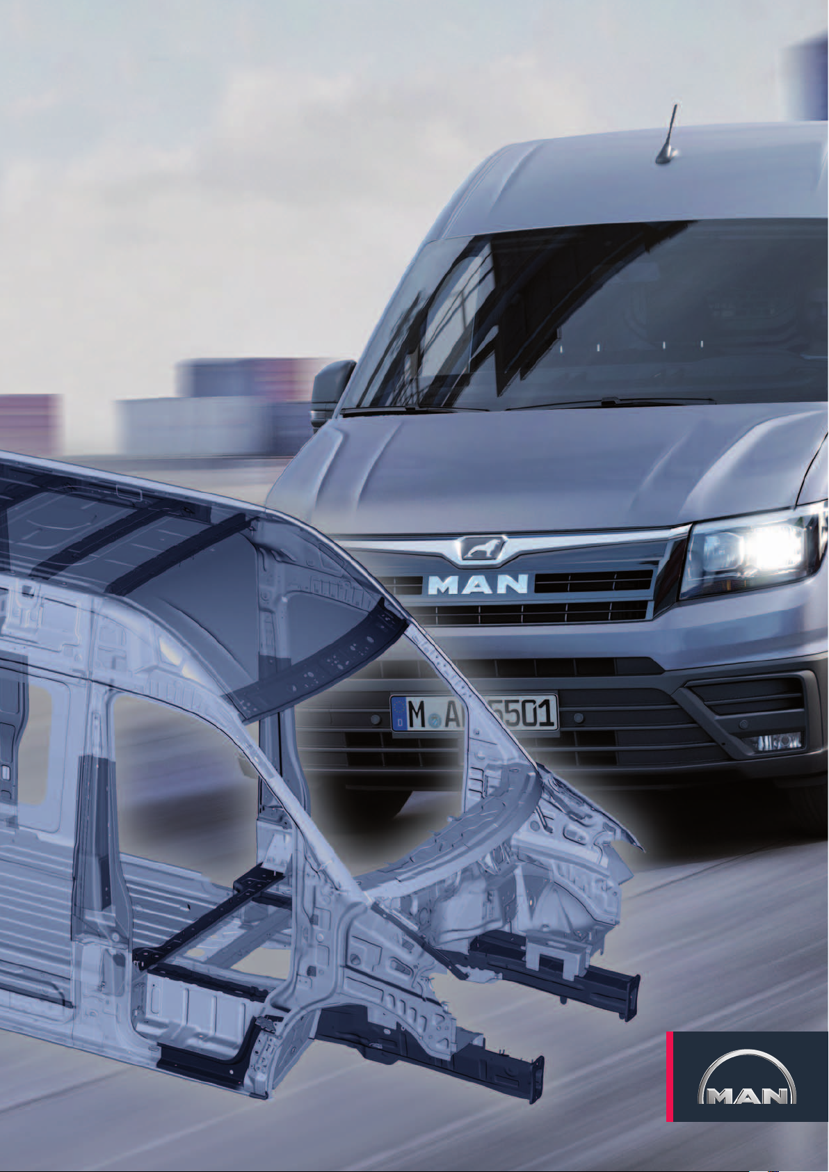
The MAN TGE is a completely new commercial vehicle development. One of the most important goals
in the development of the TGE was to meet the increased requirements for vehicle safety, comfort, and
the optimization of payload and packing dimensions. For the car body, these goals are achieved by
using a modular body concept with a uniform front end, the increased application of adhesive technology and the use of more body panels of highest material grades. With the TGE, MAN is using higheststrength hot-formed body panels for the first time. Thanks to the completely new development, a large
number of different derivatives in 2 wheelbases, 3 vehicle lengths and 3 roof heights can be realised in
closed and open superstructures.
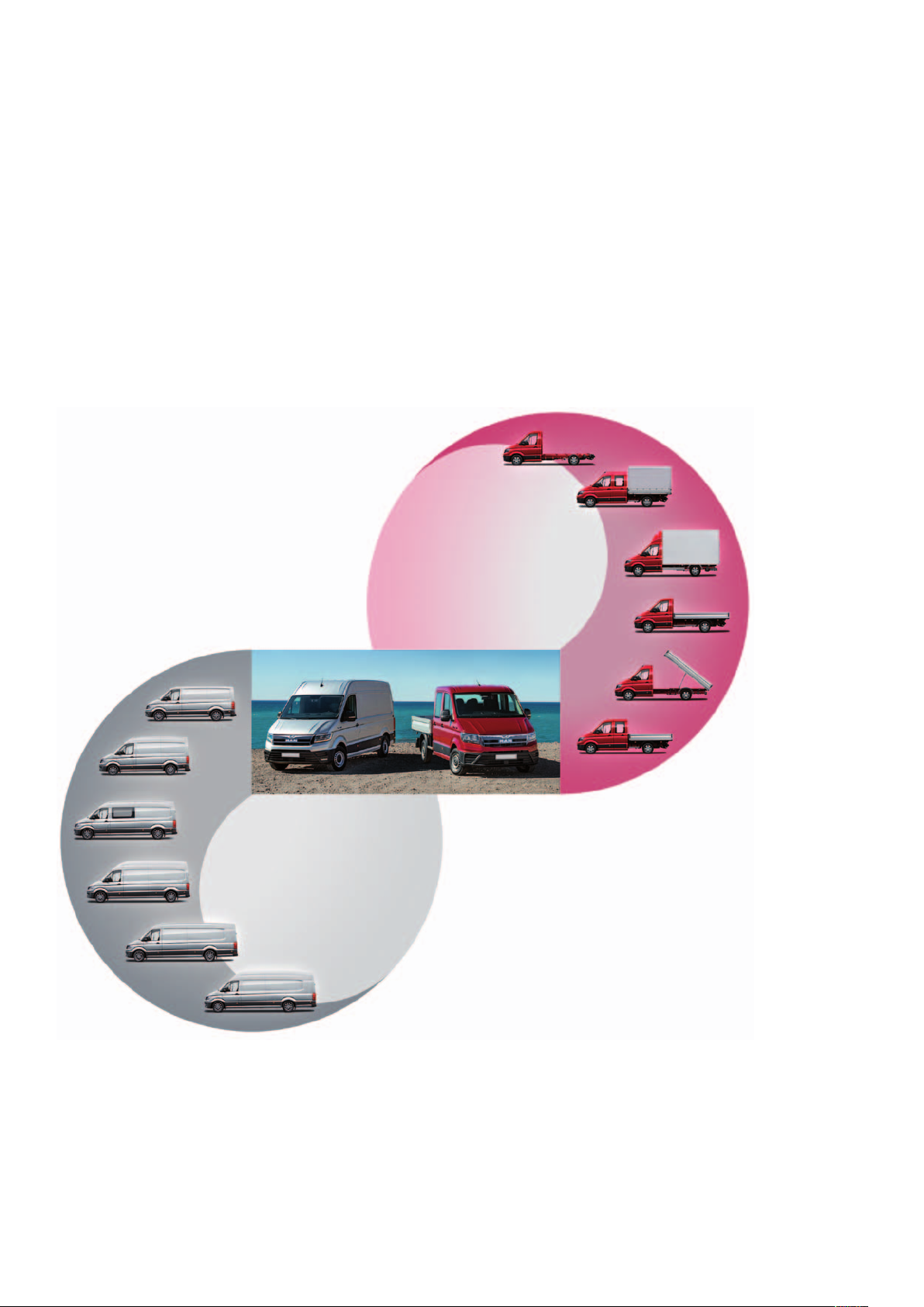
In addition, the Group's internal business unit “NC - Customized Solution”
offers numerous bodies and conversions such as box bodies, flat beds with
and without tarpaulins and three-way
tippers directly ex works.
Technical status January 2018
m103_160
The new design is based on the design
of the 6th-generation Transporter series
and relies on a consistently aerodynamic basic shape that is implemented
throughout all derivatives.
This chapter of the MAN TGE Guide
series shows you the special features of
the MAN TGE in terms of bodywork and
occupant protection.
2
Page 3
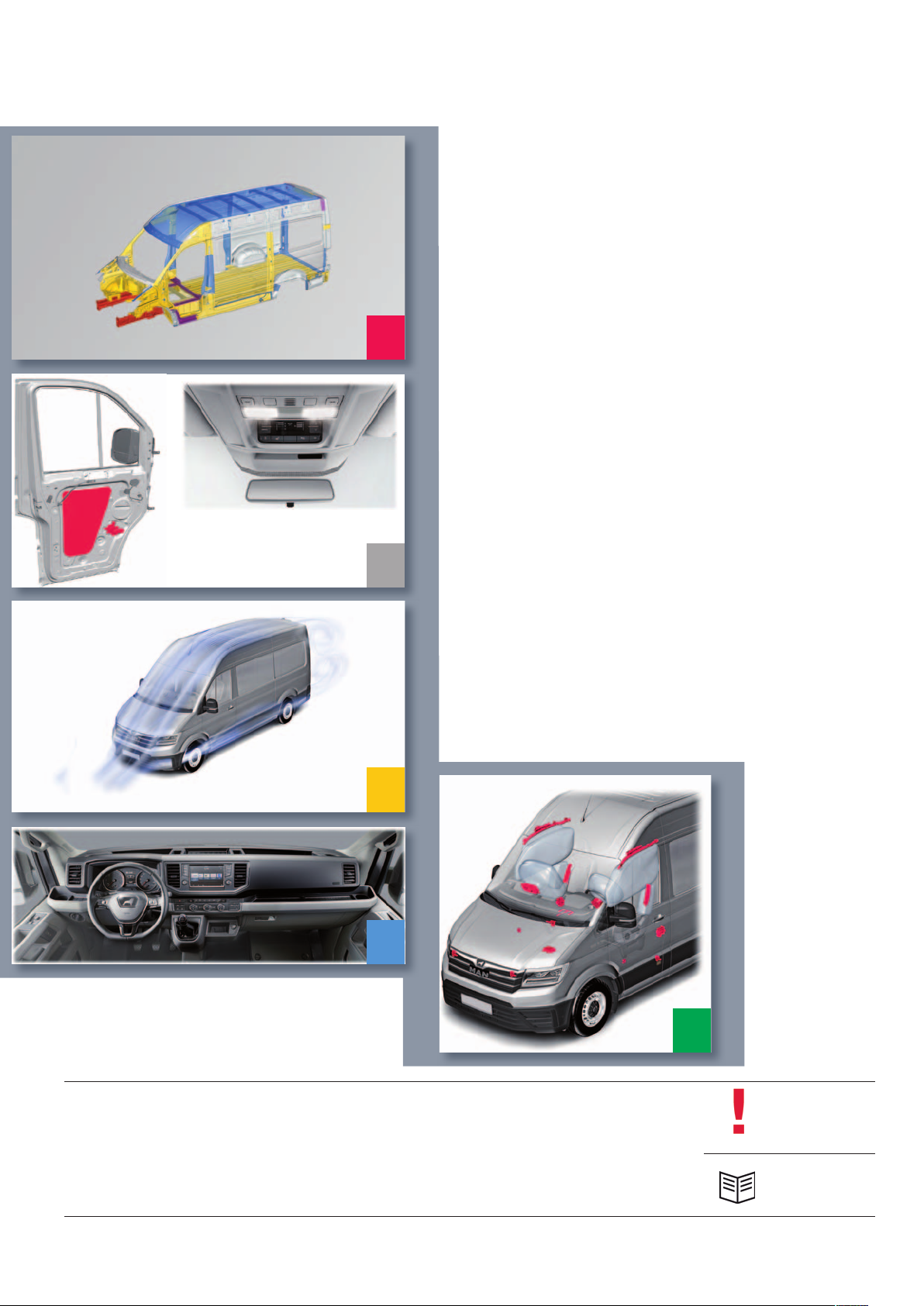
taBle of contents
4 IntroductIon
6 Body structure
12 Body repaIrs
6
14 Body assemBly
30 aerodynamIcs
14
30
32
32 InterIor equIpment
40 occupant protectIon
47 Glossary
40
The MAN TGE Guide teaches the basics of design and function for sales and after-sales of new vehicle models, new
vehicle components or new technologies.
The MAN TGE Guide is not a sales manual nor a repair guide! Specified values are for the sake of easy understanding
only and refer to the data status valid at the time the MAN TGE Guide was created.
The contents are not updated.
Please use the appropriate technical literature for customer advice, maintenance and repair work.
Note
Reference
3
Page 4
IntroductIon
The modular design of the MAN TGE
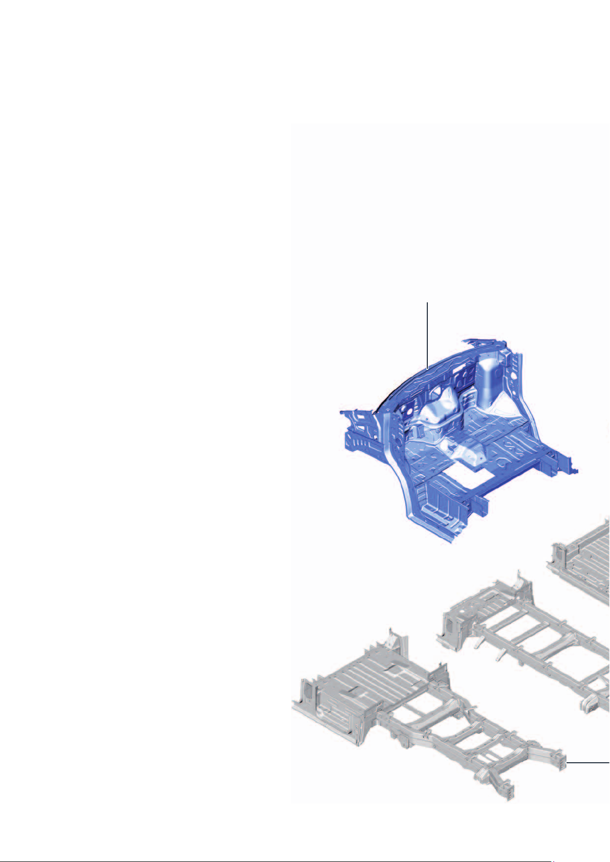
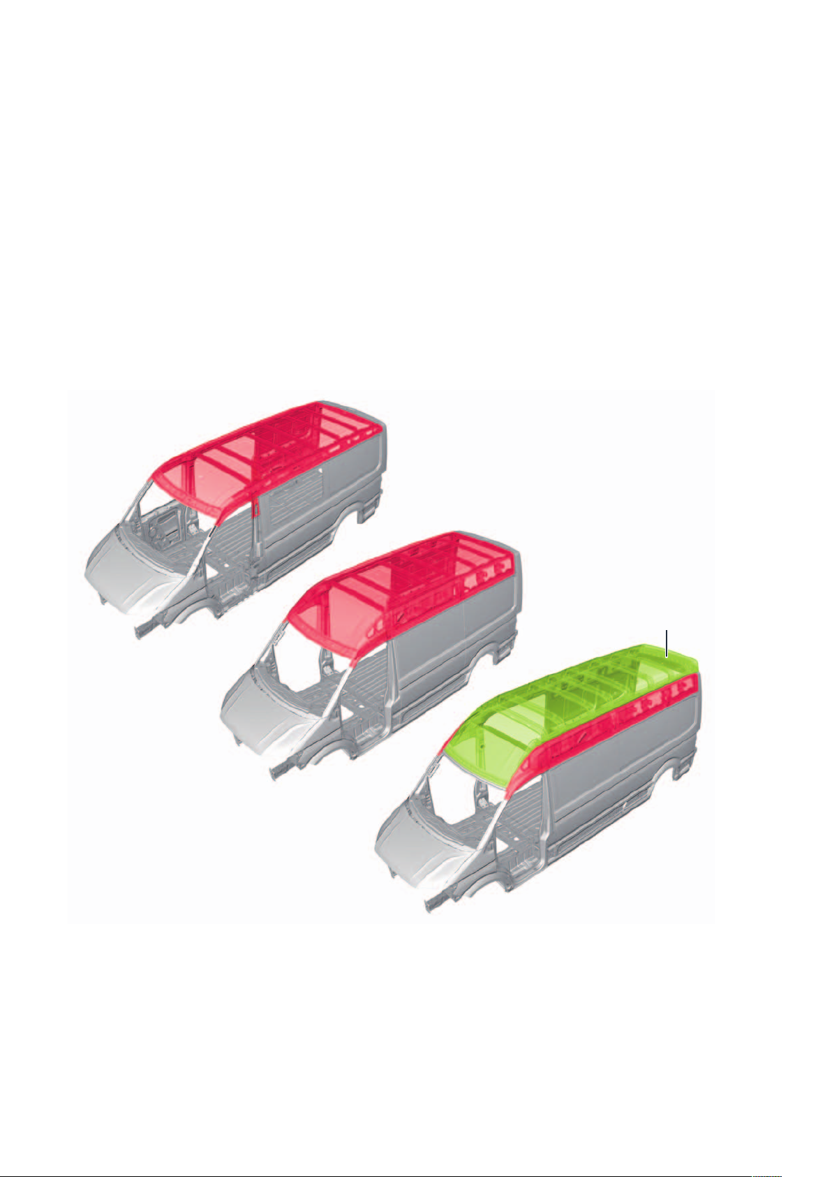
An important goal in the development of the body structure was the creation of as many identical parts as possible. Thus, the body structure is based on a modular concept. The numerous derivatives and variants, such as
different wheelbases and roof heights, must be produced with high synergy effects.
The floor structure in the front area of the MAN TGE is
the same for all vehicle variants.
The front end consists of the front side members, the
inner mudguards, the spray wall area, the lower area of
the A-pillars and the floor assembly in the area of the
driver's cab.
There are clear differences in the rear section with
regard to the floor assembly, the floor plates, the side
members, the wheel arches, the ladder frame and the
corresponding connecting parts and reinforcements.
Their design and layout is determined by the following
factors:
Uniform front vehicle
(enlarged image)
Type of drive
Wheelbase
Rear overhang
Type of superstructure
Single or dual tyres on the rear axle
Some examples of the modular structure can be seen
in the picture on the right.
4
Page 5
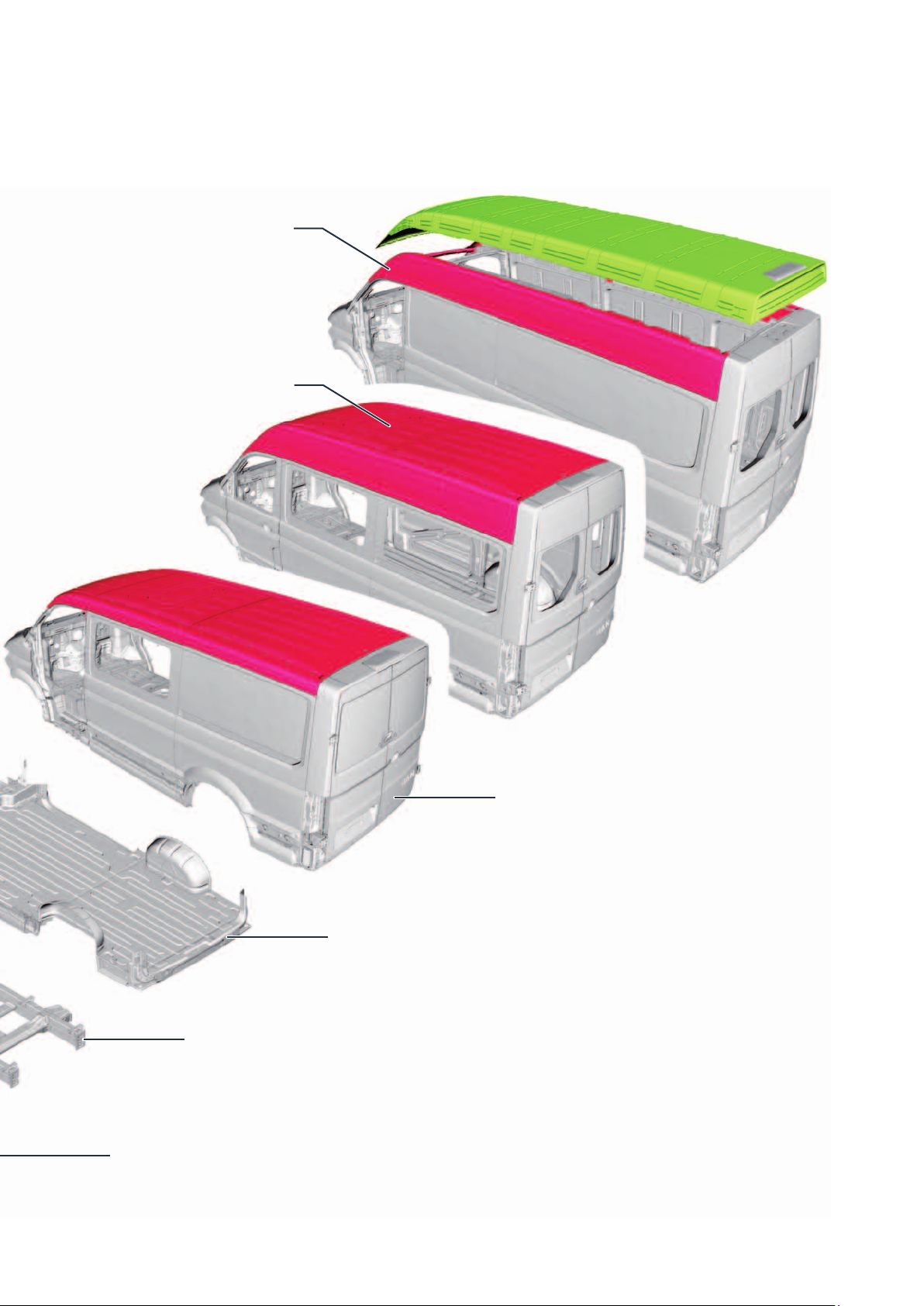
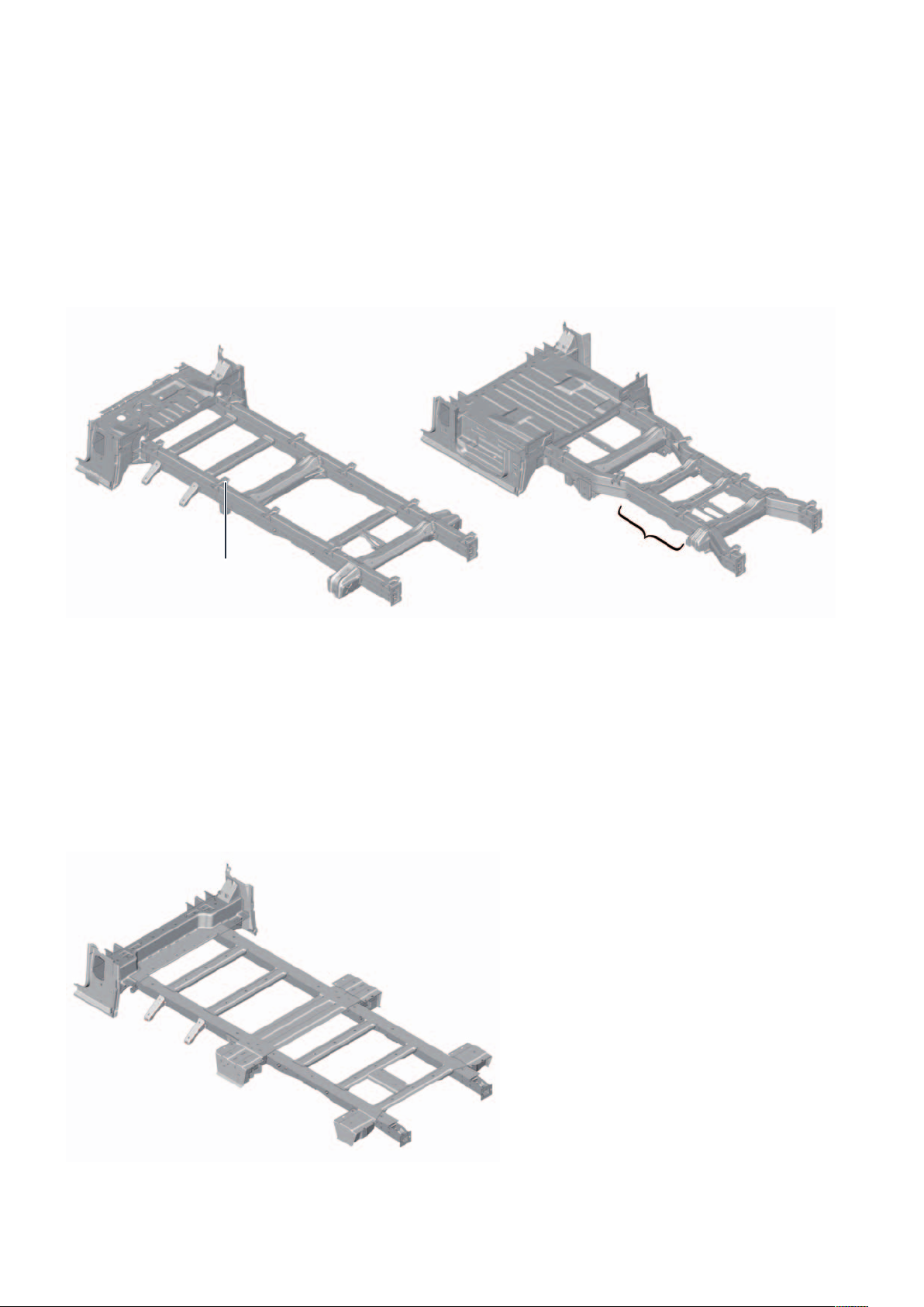
Superstructure of closed panel van,
long wheelbase with super high roof
Superstructure of fully glazed panel van,
short wheelbase with high roof
m103_110
Ladder frame for single cabin
Ladder frame for double cabin with
increased space for dual tyres
Superstructure of partially glazed panel van,
short wheelbase with normal roof
Floor assembly for panel vans
5
Page 6
Body structure
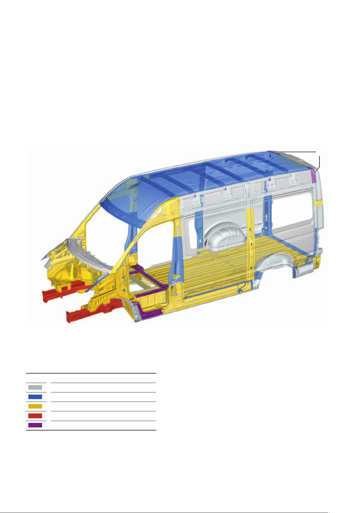
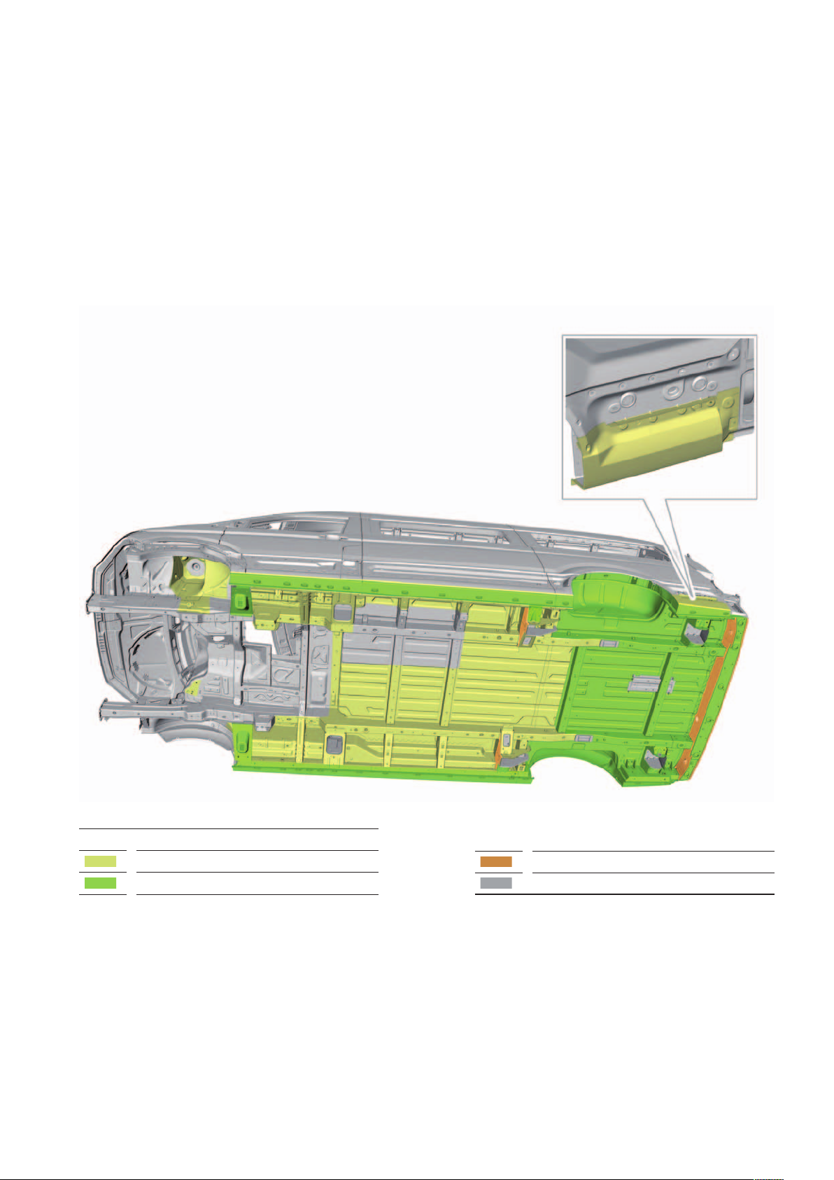
The body structure
In addition to the modular structure, the
development of the new body structure
was focused on achieving high crash
safety with low weight and optimizing
aerodynamics.
By achieving these goals, the MAN TGE
has been optimized in terms of payload,
economy and crash safety.
1*
Legend: Strength of steel sheets
(yield strength “Re”)
< 160 MPa soft
< 220 MPa high-strength
< 420 MPa higher-strength
< 1000 MPa highest-strength
> 1000 MPa highest-strength hot worked
m103_161
The attachments not shown, such as
doors, bonnet, mudguards, and side
panels are made of soft body sheet
<160MPa.
* Legend see page 7
6
Page 7
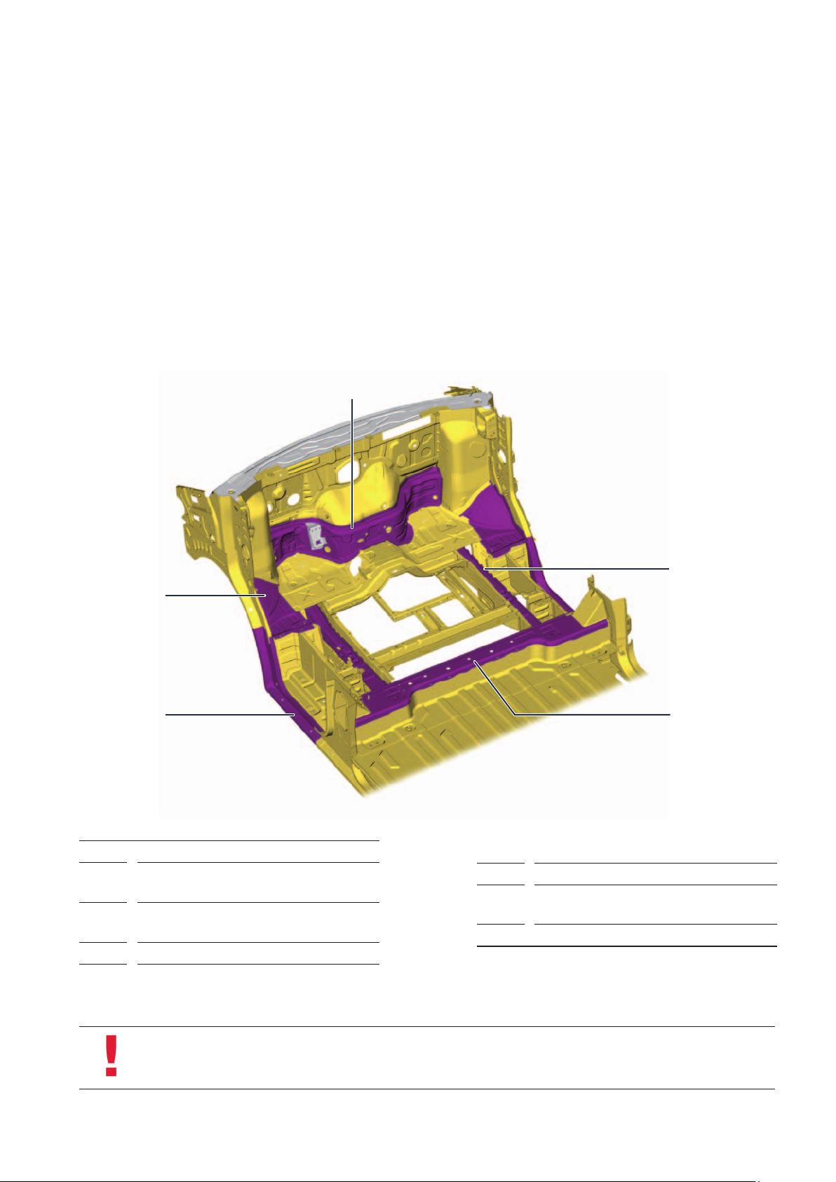
The increase in strength and weight reduction are achieved by the following design measures:
Geometrical lightweight construction
Increasing use of high-strength and
highest-strength hot-formed steels
3
Targeted use of modern processes in
the production of steel sheets, e. g.
hot forming, bake hardening and
tailored blank technology
4
Load-appropriate application of
joining processes such as resistance
spot welding, laser soldering, laser
welding and bonding
5
Legend
1
2
3
2
Rear roof corner reinforcement area
(shown in graphic m103_161 on page 6)
Reinforcement area for A-pillar base and
sills
Wheel arch area
Note
Hot-formed sheets must be treated separately during repair.
For more information, see the relevant service literature.
6
m103_162
4
5
6
Front transverse wall area
Area of longitudinal member reinforcement
in the driver's cab
End part area
7
Page 8
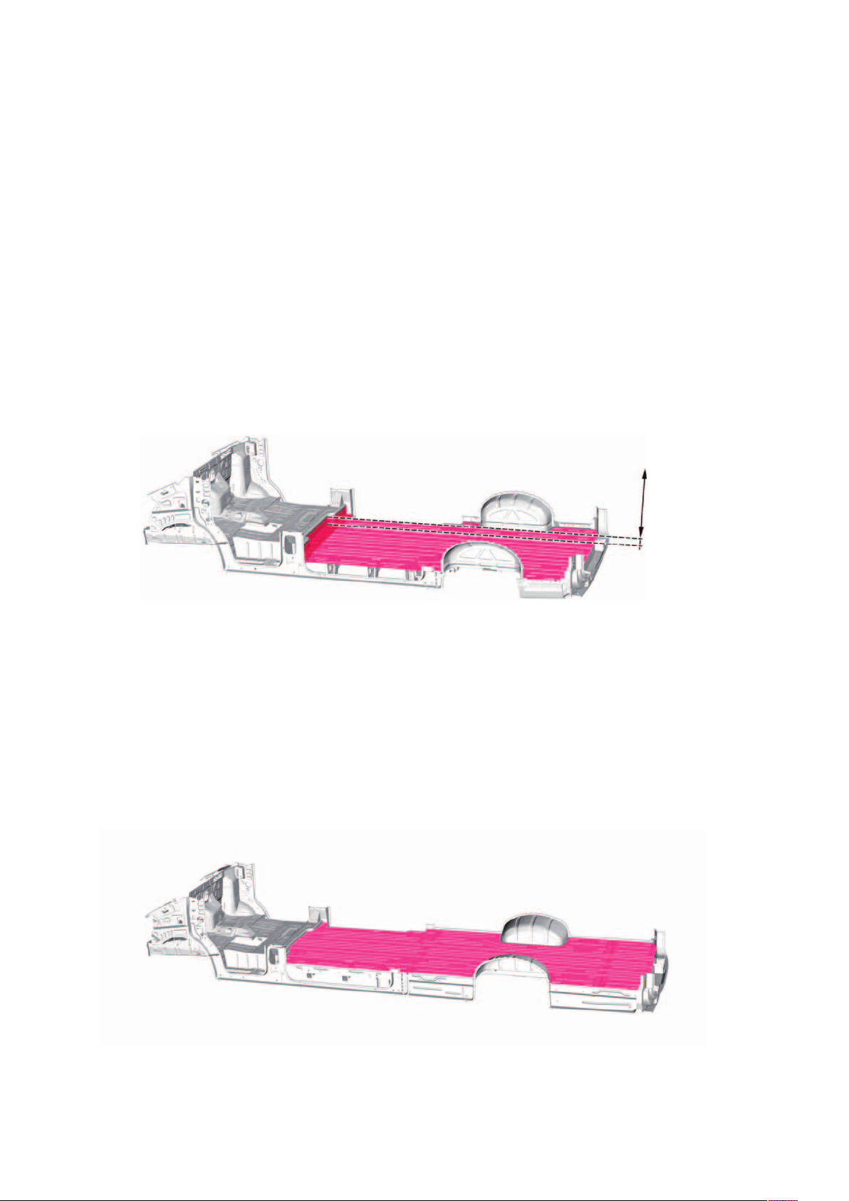
Floor structure on closed body
The closed bodies of the MAN TGE are available with two different floor structures depending on the drive concept.
Vehicles with front-wheel drive
In these vehicles it was possible to
lower the loading floor by 100 mm
compared to the driving space level, as
no installation space is required for the
cardan shaft.
Floor structure (loading floor -100 mm)
Example: short wheelbase
This results in advantages such as
100 mm greater interior height
a resulting larger loading volume
a correspondingly lower entry height
for vehicles with sliding doors and
rear doors.
-100 mm
m103_111
Vehicles with all-wheel and rear-wheel drive
These vehicles have a continuous
loading floor at the level of the driving
area.
Floor structure (loading floor at driver's cab level)
Example: long wheelbase with overhang
The resulting installation space is
required for the installation of the cardan
shaft and the rear axle drive.
m103_112
8
Page 9
Roof variants on closed superstructure
The normal roof and the high roof are
made of sheet steel.
Transverse roof crossmembers reinforce
the roof.
The super high roof is made of polyester. Transverse roof crossmembers are
laminated into the polyester roof for
stabilization. In addition, a reinforcing
frame is integrated in the roof.
Roof height 1
Normal roof (H2*)
Roof height 2
High roof (H3*)
Thesuper high roof is connected to the
body by bonded and screwed connections. After assembly, the resulting gap
between the body and the polyester
roof element is sealed with joint seal.
Roof height 3
Super high roof (H4*)
Polyester roof
m103_113
* These parameters are explained in the “MAN GUIDE 101 TGE Fundamentals” on page 9.
9
Page 10
Open vehicle superstructure with ladder frame
Vehicles with 3.5 t and 5.0 t have different ladder frames. These are adjusted to the respective
payload and the tyres used.
Ladder frame 3.5 t Ladder frame 5.0 t
Space for
Space for
dual tyres
dual tyres
A flat frame is available for the use of
special superstructures (e. g. motor
homes). It is based on the deep base
frame (without base plate) of the Crafter
Flat frame 3.5 t
panel van and is about 193.5 mm lower
than the ladder frame for the open
superstructure.
m103_163
The flat frame is optionally available in
conjunction with an axle widened by
about 200 mm.
10
m103_164
Page 11
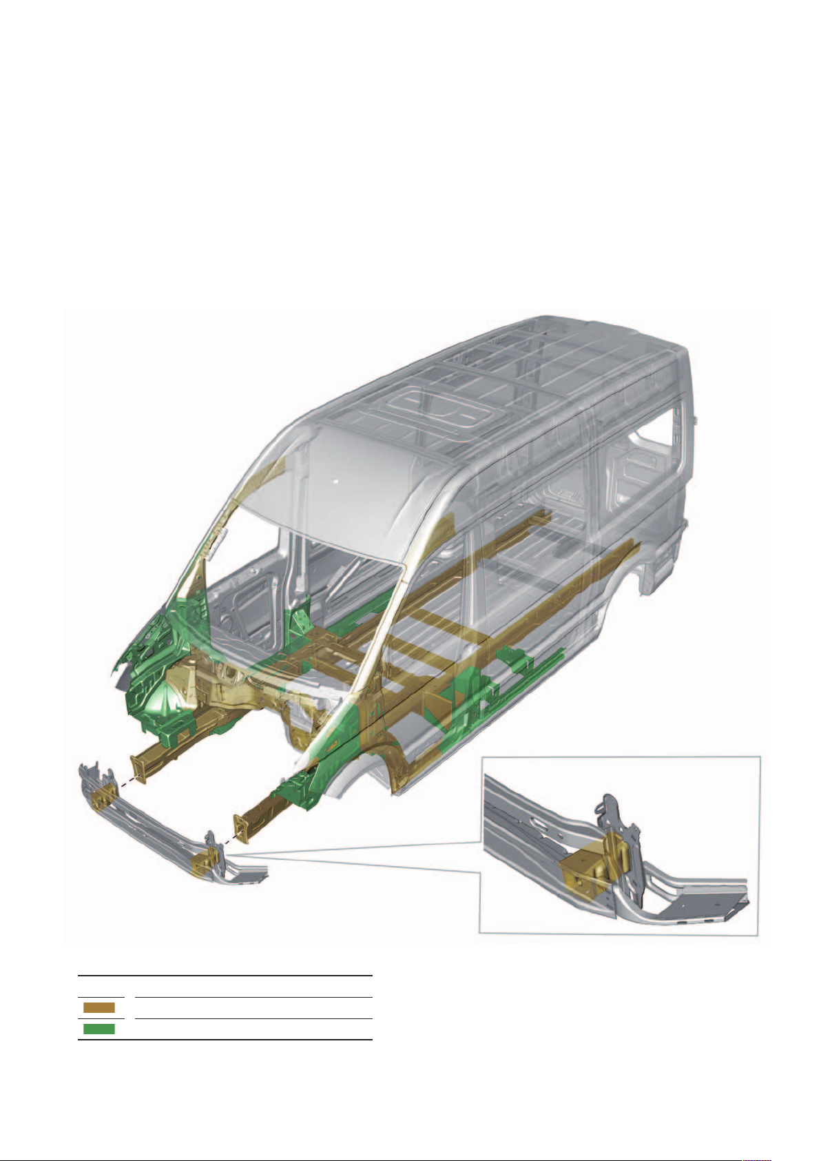
Load paths in the body structure
To absorb high energies in a front or
side crash, certain components of the
body structure are designed accordingly
and made of steels with specially
selected strengths (shown in brown).
Inthe event of a crash, the energy
absorbed can thus be reduced in a
defined manner through targeted deformations. Other selected areas of the
body structure have a supporting
function (shown in green). They have the
task of stabilizing the driver's cab in the
event of a front or side crash.
Legend
m103_165
Components for high loads
Components for support functions
11
Page 12
Bodywork repaIr
The joining processes
Different joining processes are used in the MAN TGE for design reasons, such as resistance spot welding, laser
soldering, laser welding, and bonding technology.
The paint structure
The MAN TGE is available with solid or metallic paint. Both paint variants finally receive a clear varnish top coat.
Minimum coating thickness values
Legend
12
Outer region
Visible, unobstructed
areas above the
main sill flange
Cathodic dip painting
Primer
Door interiors
Entrance areas for
defined exterior
colours
Load compartment
floor, uncladded
Bottom and wheel
arch
Base coat
Clear lacquer
Load compartment,
uncladded
Side panels
Roof
m103_166
Page 13
The corrosion protection
The underbody, the front and rear wheel
arches and the outer panels of the sill
are preserved with underbody protection in layer thickness values between
400μm to 1000μm.
The layer thickness values can deviate
upwards (maximum 2000μm).
The exterior body panel behind the rear
wheel arches is sealed with underbody
protection in the visible area. The PVC
Example - closed superstructure
underbody protection is applied directly
to the cathodic dip painting. Cavities and
mounting surfaces, e. g. for the leaf
spring support, are PVC-free. All seams
and folds on the underbody are sealed
with joint seal.
Legend
~ 400μm
~ 700μm
All cavities in the lower part of the body
and on the add-on parts are treated
with cavity wax.
The layer thickness of the cavity wax is
> 30μm. The cavities of the doors are
preserved to a height of 80 mm. The
body of the MAN TGE is galvanised
except for the hot-formed sheets and
some reinforcements inside the body. All
doors, the bonnet and the mudguards
m103_167
~ 1000μm
Cathodic dip painting
are hot-dip galvanised. The remaining
galvanized sheets are electro-galvanized.
13
Page 14
Body assemBly
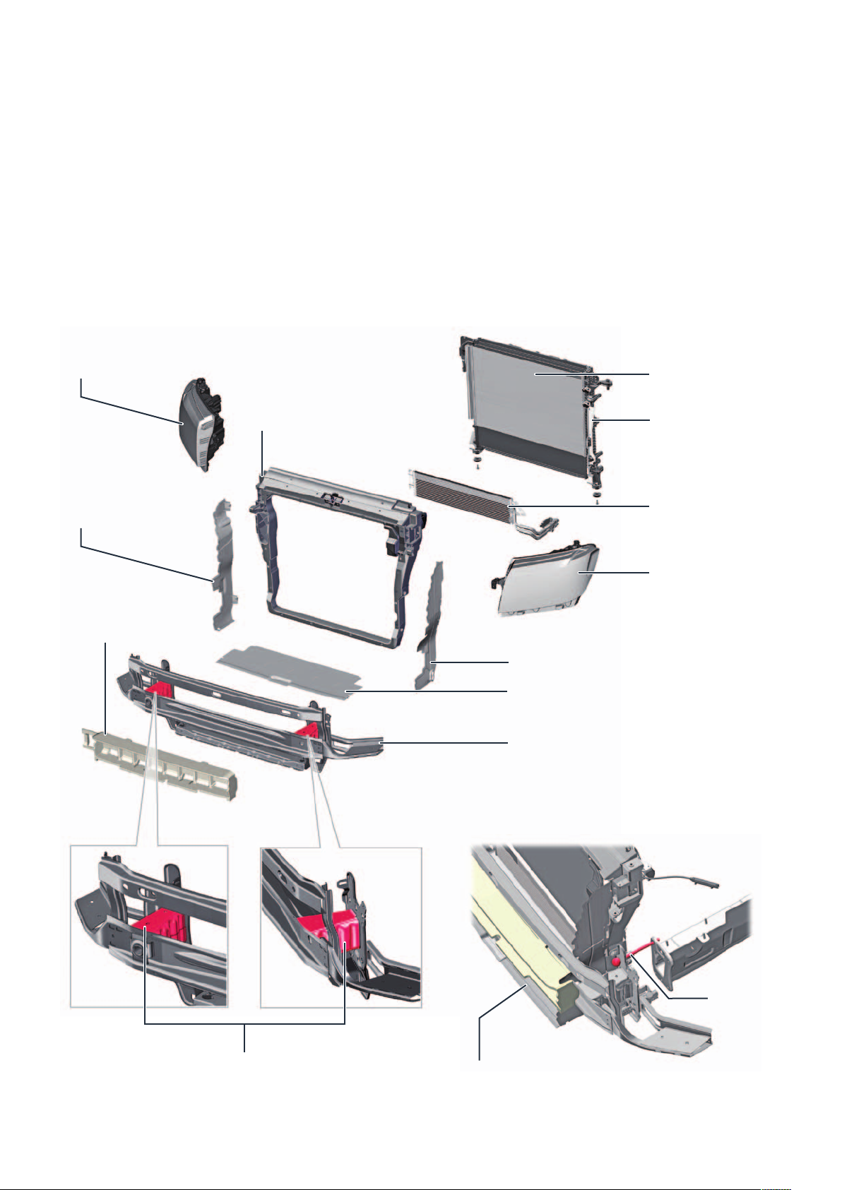
The front-end
The mounting support is made of sheet
steel and serves to accommodate the
radiator, the additional oil cooler and the
condenser of the air conditioning
Right headlamp
Mounting support
Right airflow
system. A reinforcement for the step is
incorporated in the mounting support.
The deformation element serves for
absorbing crash energy in the event of a
frontal impact. The front end can be
brought into service position with the
T10093 guide rods to improve accessibility.
Condenser
Radiator
Additional oil cooler
Left
headlamp
Foam part
m103_115
Left air flow
Bottom separation part
Bumper crossmember
Front-end service position
Guide bar
T10093
14
Deformation element
Service position
Front-end pulled forward about 100 mm
m103_114
Page 15

The front bumper
The front bumper essentially consists of
3 components, the bumper cover, the
radiator grille and the panel. These are
connected to each other exclusively via
Cover for
step
Supporting member
clip connections. The step and fog
lights are integrated in the bumper
cover.
Bumper crossmember Reinforcement for step
The panel is fitted as standard on the
MAN TGE in a painted version, and is
also available as a robust grained
version as an option.
Radiator grille
Chrome trim
Step
Bumper cover
Panel ACC sensor support
(clipped from behind in the lower
part of the bumper cover)
Step Cover for
step
Supporting member
m103_116
15
Page 16

The rear bumper
The rear bumper is constructed in three
parts to improve ease of repair. The
middle section of the bumper can
Three-piece bumper
optionally be designed as a step.
Thestep is reinforced by a frame part.
Vehicles with steps are not available in
combination with trailer hitch.
Bumper middle section with step
Frame part to reinforce the step
m103_117
16
m103_118
Page 17

The door concept
Driver/passenger doors
The driver/passenger doors of the MAN
TGE consist of an outer panel and an
inner panel. These are constructed in
one piece. All internal components are
installed via a large mounting opening.
The door foil closes the mounting
opening.
Pressure sensor
G780
Door foil
m103_119
Exterior mirrors
The door mirror is connected to the door with two screw connections. The clip on the mirror base cover and the
sliding carriage serve as a mounting aid.
Dismantling position:
Sliding carriage open
Mirror base
Sliding carriage
Mounting position:
Sliding carriage locked in
place
Door panel
m103_120
17
Page 18

Sliding door
When fitted, sliding doors are installed
as standard on the body side opposite
the steering wheel side. The MAN TGE
is optionally available as a double loader
with a sliding door fitted on the left and
right.
Top stop
The door is guided by rollers in the top,
middle and bottom guide rails. For the
different roof heights, the sliding doors
are available in two door heights, one
for the normal roof and one for the high
roof and super high roof. For doors with
increased thermal insulation, e. g. in
Picture shows door of high roof
Upper
roller guide
Outside handle
(concealed)
refrigerated vehicles, there is a different
version of the central roller guide with
large lift-out. This means that the open
sliding door is about 25 mm further
away from the side panel of the body in
the rear area.
Bottom stop
Centre roller
guide (normal
lift-out)
Door lock
(concealed)
Centre roller
guide (large
lift-out)
Pivot
Lower roller
guide
18
m103_121
Page 19

Rear doors
The rear doors are designed as double
doors. The maximum opening angle for
both rear doors is 180°, optionally 270°
(standard for extra long vehicles). In this
case, magnetic stops are used to hold
Picture shows door of high roof
6 3 5 3 6
1
9
2
1
the open doors securely. On the sliding
door side, the opening angle is slightly
smaller in order to avoid collisions with
the sliding door. The right double door
always opens first. There are two differ-
Legend
1
2
1
3
4
5
6
7
8
2
9
10
1
11
ent door heights, one for the normal
roof and one for high and super high
roof.
Hinge
Door-stay
Rotary latch lock
Lower lock
Seal
Guide key
Guide ring
Door lock (concealed)
Inside operation
Stop (bottom left picture)
Magnetic stop (bottom left picture)
8 7 7 4
Rear door with magnetic stop - closed Rear door with magnetic stop - 270 degrees open
m103_122
1110
m103_123 m103_124
19
Page 20

Door handle with locking cylinder
The door handles in the MAN TGE are particularly ergonomic and equipped with innovative safety features. The driver's door
and the rear wing door are fitted with locking cylinders.
The images show the door handle of the left-hand drive driver door
Anti-theft screw Slide
Locking cylinder Door knob
Bearing support
m103_125
Locking cylinder Cap (cap with hole)
The door handle is guided in the bearing
support. The tappet of the door handle
engages in the reversing lever in the
bearing support. To operate the door
Tappet
Bowden cable
lock, the tappet moves the reversing
lever, which in turn operates the
Bowden cable to the door lock. The
locking cylinder is mechanically locked
Reversing lever
m103_126
via the slide of the bearing support and
secured with an anti-theft screw. The
cap serves to protect the locking cylinder.
20
Page 21

Door handle without locking cylinder
Filling parts (cap without hole) are fitted on the front passenger door and the sliding door instead of locking cylinders.
The images show the door handle of the sliding door on the right
Bearing support
Filling part
(cap with hole)
Door knob
m103_127
Filling part
(cap without hole)
Slide
Reversing lever
Tappet
Bowden cable
The design and function of the door
handle are basically the same as for the
door handle with locking cylinder. The
only thing missing is the locking cylinder
m103_128
with its anti-theft screw. The design of
the slider has been adapted with
respect to its shape. The filling piece
replaces the missing locking cylinder
and is mechanically secured by the slide
of the bearing support.
21
Page 22

The lights
Interior lamps
2 lights at the roof gallery
There are 2 lights on the underside of
the roof gallery for the driver and the
passenger.
Lights in the load compartment
m103_168
Depending on the respective country
setting, there are different lights in the
load compartment.
Incandescent lamp above the rear door
The other variant is equipped with
4LED lights in the roof crossmembers.
One version has one incandescent lamp
each above the rear and side door.
m103_169 m103_170
Incandescent lamp above the side door
22
m103_171
Page 23

Tail lights with closed vehicle superstructures
The tail lights are attached using 2 screw connections and 2 clip nut connections.
The external connection of the rear
lights is a clip nut connection. In the
support plate for the clip nut, the outer
plate of the side part and the corner
plate of the D-pillar overlap.
To prevent water ingress, the mounting
hole for the clip nut is covered with a
self-adhesive sealing foil (zinc foil).
After dismantling the tail light, the
sealing foil must be checked for
damage and replaced if necessary.
m103_129
m103_130
Screws Clip nut
Side part D-pillar
m103_131
Sealing foil
Mounting hole for clip nut
Note
Further information on the rear lights with closed vehicle superstructures can be found in the corresponding service
literature.
23
Page 24

Raised brake light
The raised third stop light can optionally be equipped with an additional reversing camera. The housing of the brake light is
fastened to the roof crossmember with eight metal clips and two screw connections. The metal clips and screws are accessible
through the openings on the underside of the roof crossmember.
Third brake light without reversing camera
Reversing camera
m103_132
Third brake light with reversing camera
Metal clips
Screw
Brake light power supply
Line for video signal
from the camera
Camera power supply
24
m103_133
Screw
Page 25

Side marker lights
Depending on the model, side marker lights in LED technology are installed in the MAN TGE. These are integrated into the side
protectors of the closed vehicle.
Side marker lights
In open vehicles, the first side marker light is integrated in the side protector. The other
side marker lights are mounted on a support on the superstructure.
m103_134
Side marker lights
m103_135
25
Page 26

The side protectors
The side protectors protects the lower part of the body
against external damage.
The ultrasound sensors for the side protection and the
side marker lights are integrated into the side protectors, too.
Adhesive area
Cable passageway Double-sided adhesive tape Side protectors
Side marker light
Top clip row
Centering pins
Bottom clip row
m103_136
Ultrasound sensorScrews
The side protectors are generally clipped and additionally bonded with double-sided adhesive tape at the upper edge.
They are additionally secured with screw connections to the driver, passenger and sliding doors. The protectors do not have any
direct contact with the body except on the adhesive surface. The adhesive prevents relative movements between body and side
protectors and thus avoids corrosion and damage to paintwork. Ultrasound sensors and side marker lights are attached to the
side protectors with double-sided adhesive tape. The screw connections on the side protectors serve to protect against theft.
This prevents easy disassembly and blocks access to the vehicle via body openings in the doors.
26
Page 27

The glazing
The windscreen, the rear windows and the side windows are bonded. Sliding windows for closed vehicles and hinged windows
for the double cabin are offered as options.
Sliding window in the side panel
m103_137
Heated windscreen
The windscreen heater helps to defrost the windscreen and only works with running engine.
Ground terminals
m103_172
Heating wires shown
symbolically
Connection for
left heating panel
Connection for
right heating panel
m103_138
27
Page 28

The trailer hitch
The trailer hitch for the MAN TGE is available in two different versions:
with rigid ball head
as a variable variant with the “Varioblock” system by the company Rockinger
With the variable variant, a detachable ball head or a jaw coupling can be attached to the hitch. The maximum towing capacity
of the MAN TGE is 3500 kg. Vehicles with rigid and variable trailer hitches can be equipped with a side step.
Version with rigid ball head Variant with variable coupling
Step
Rigid ball head
Hitch Jaw coupling
m103_140
The roof rack
The guide rails for the roof rack are bolted to the body roof
and reinforced from the inside with another bolted profile
piece in the area of the D-pillar. The connection points are
fitted as standard. This means that the guide rails for the
roof rack can always be retrofitted.
Adapter
Rigid ball head
m103_140
Guide rail
m103_141m103_173
Possible roof loads:
Normal roof up to max. 300 kg
High roof to max. 150 kg
28
Reinforcement on
the D-pillar
Page 29

The pre-assembly stages for special
superstructures
Complete open chassis without platform bodies are offered to body and conversion manufacturers. Furthermore, incomplete
chassis are offered allowing an economic individualization. There are two types of incomplete chassis: cowl and platform.
Cowl
An open chassis without roof and rear wall is called a cowl. This version favours conversion to delivery vehicles, mobile homes or
ambulances, for example.
m103_142
Platform
The platform lacks the complete upper body of the driver's cab as well as doors, bonnet, fenders, bumpers, headlights and
seats. This version favours, for example, the conversion to fully integrated delivery vehicles or motor homes.
m103_143
29
Page 30

aerodynamIcs
Aerodynamic optimization
The basic shape of the body was
radically optimized with regard to
aerodynamics. For example, the design
of the bumpers featuring a special air
duct creates an air curtain in the area of
Aerodynamically optimized parts:
Roof tapering
Rear tapering, lateral
Rear spoilers
A-pillar
Exterior mirrors
Bumpers
Step
the front wheels. The roof tapering in
connection with the lateral rear tapering
ensures an aerodynamically optimal air
flow on the outer contour of the body.
This form is also called the “fish belly”.
It is the best aerodynamic design
for a vehicle body. Special spoilers at
the rear of the vehicle provide an aerodynamically favourable flow interruption.
Targeted air guidance past the wheel
(air curtain)
Steps
The front bumper has two steps on the left and right.
These are used to climb up, for example to clear the
windscreen of snow and ice. The covers in front of
these are locked in the bumper and can be removed
to the front. The shape of the covers optimises the air
flow.
m103_144
30
CoverStep
m103_145
Page 31

The consumption optimization package
Underbody panelling
Flow losses on the underbody of a
vehicle play a significant role in
increased driving resistance.
The underbody of the MAN TGE has
been specifically designed with smooth
surfaces to minimise flow losses on the
underbody.
An almost complete smoothing of the
underbody has been achieved by
cladding. For vehicles equipped with the
efficiency package, underbody panels
are used which not only improve aerodynamics but also significantly reduce
interior noise. These underbody panels
are only available for front-wheel drive
vehicles. The aerodynamic package
also includes an additional spoiler on
the left and right transverse links.
Spoiler on
transverse link
m103_174
31
Page 32

InterIor equIpment
The storage concept
Dashboard
The workplace of the MAN TGE has been tailored to the driver. In addition to numerous storage and stowage compartments, it
offers connection options for mobile devices.
Cup holder Storage compartment
Storage compartment with
12 V socket
with USB port and
AUX IN connector
Storage compartment/
ashtray (hiking ashtray)
Centre
storage tray
12 V socket/ socket
Cigarette lighter
Storage tray with
12 V socket
illuminated, lockable,
chilled
Cup holder
m103_146
Storage trayGlove compartment
Door panel
Storage compartment with
bottle holder
Storage compartment with
support for warning triangle and first aid kit
32
Storage tray
m103_175
Page 33

Roof gallery
The roof gallery is optionally available with 2 spacious storage compartments and 2 DIN slots (if equipped with a second
evaporator, only 1 DIN slot is available).
Storage tray DIN slots Storage tray
m103_147
Side panels in the load compartment
Multi-part side panels made of plastic and plywood are optionally available in different heights.
m103_176 m103_177
Side panels made of plastic Side panels made of plywood
33
Page 34

The seat concept
Single seats in the driver's cab
Individual seats in different versions are available for the driver's cab.
Rigid
seat
Backrest angle adjustment • • • • • •
Longitudinal adjustment • • • • • •
Height adjustment • • • • •
Seat cushion angle adjustment • • • • •
Manual 2-way lumbar support •
Electric 4-way lumbar support • • • •
Comfort
seat
Comfort
“Plus”
seat
“ergo
Comfort”
seat
“ergo
Activ”
seat
Swivel seat
1 x armrest inside •
2 x armrest inside/outside • • • •
Suspension unit with
adjustable weight
Seat depth adjustment • •
Massage function •
Rotation function •
• •
34
Page 35

“ergoComfort” / ”ergoActive” seat
The “ergoComfort” and “ergoActive”
seats have been consistently developed to meet the physical needs of the
driver. By means of two coil springs
and a gas pressure damper a vertical
oscillation behaviour adaptable to the
body weight is generated. This ensures
comfortable and fatigue-free sitting,
Headrest adjustable in two heights
Hand wheel for adjusting the
backrest inclination (concealed)
Armrest, continuously
adjustable
especially on long trips or poor roads.
The feeling of well-being is enhanced by
the adjustment of a large number of
individual seating positions. The lumbar
support integrated in the backrest
relieves the spine. The seat is available
as “ergoComfort” (without massage
function) or “ergoActive” (with massage
function). The seat has already been
awarded the AGR seal (Aktion Gesunder Rücken, Healthy Back Campaign)
for its exceptionally good ergonomic
properties. The control unit for massage
function and lumbar adjustment is
located under the driver's seat.
Lumbar support with motor for
longitudinal adjustment of
driver seat lumbar support
V125 and motor for height
adjustment of driver seat
lumbar support V129
Handle for
mechanical
seat depth adjustment
Lever for
longitudinal seat
adjustment
Lever for
blocking the
vertical movement of
the suspension seat
Hand wheel for adjusting
the body weight on the
suspension seat
Key for
back massage function
(only with “ergoActive”)
Side airbag
2 coil springs
Gas pressure absorbers
Seat height adjustment lever
Control unit for massage function
Hand wheel for adjusting the
seat surface inclination
Switch for adjusting the driver's
seat lumbar support E176
m103_148
35
Page 36

Double passenger bench
In standard equipment, the seat cushions can be folded individually. Below is
a covered storage compartment inside
the seat frame. Optionally, the inner
backrest is also equipped with a folding
function. This offers further loading
possibilities. In addition, the backrest
has a writing surface for office work
(cup holder, writing surface, pen tray,
storage compartment for e. g. tablet
computer, mobile phone, etc. and
clipboard).
m103_184
Four-seater bench for double cabin
The double cabin is equipped with a four-seater bench in the passenger compartment in the second row of seats.
Features
Storage compartment under seat accessible from
above
Seat-integrated three-point safety belts for the two
middle seats
Flat headrests, height adjustable
Retaining strap for fixing the folded up seat cushions
Retaining
strap
36
m103_185
Page 37

Load compartment with closed vehicle superstructure
The load compartment offers a wide range of possible applications.
Universal floor
The universal floor is based on the
continuous wooden floor covering of the
MAN TGE. It allows the quick set-up of
vehicle installations without having to
adapt the loading floor. This is a prerequisite for the individual furnishing of the
load compartment – without any gluing
Structure
The universal floor consists of beech
hardwood veneer sealed with a non-slip
coating. There are numerous lockable
cut-outs that can be removed. Floor
or drilling. Shelving and cabinet systems
from various manufacturers can be
easily installed and removed in line with
customer requirements. If necessary,
the components can be removed
without leaving any residue.
adapters can then be screwed in at
these points, e. g. to accommodate
cabinet systems from different manufacturers.
m103_186
The universal floor is not bonded to the
vehicle and can therefore be easily
removed. Optionally the universal floor
can be equipped with lashing rails and
lashing eyes.
Lockable cut-outs for
floor adapters
Installation system
e. g. shelf
Lockable cut-out
Screw
Anchor
m103_149
Lashing rails
37
Page 38

Load securing
Closed vehicles can optionally be
equipped with lashing rails in the side
sections, the roof crossmembers, on
the floor and on the divider in order to
secure the load. The manufacturer's
lashing rails feature a specified “airline
profile” hole profile and are screwed to
the body with hexagon blind rivet nuts
with M6 thread.
The hexagonal holes for the blind rivet
nuts are standard on all vehicles and are
located centrally and at the top in the
side parts, in the roof crossmembers
and on the divider. The blind rivet nuts
Hexagon blind rivet nut
with outer hexagonal profile are pressed
into these hexagonal holes. The hexagonal profile prevents unintentional
twisting later when fastening screws are
tightened or loosened.
Legend
Lashing rail on the
dividers
Lashing rail on the side walls Lashing rail at the roof
Lashing rail on the floor
m103_150
38
Page 39

Roof rack in the load compartment
Ladders or pipes weighing up to 50 kg
per support bracket can be stowed on
the roof rack in the load compartment.
The roof rack consists of 2 support
Lashing rail at the roof crossmember
Roof crossmembers
brackets which are attached to the
outer lashing rails of the roof crossmembers. These can be positioned variably
in longitudinal direction. When not in
Connection of the support bracket to the lashing rail
use, the two carrying handles can be
retracted to save space. The support
brackets are equipped with fastening
options from the airline profile system.
Support bracket with airline profile
Support bracket
m103_151
39
Page 40

occupant protectIon
Occupant protection
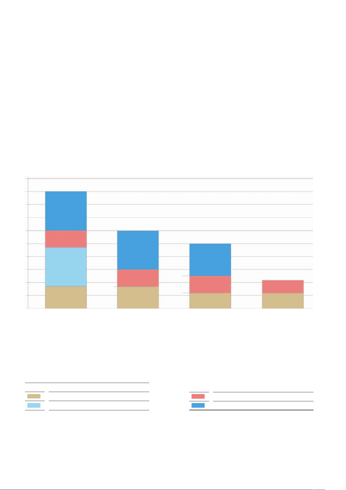
Overview of safety systems
The following occupant protection is offered in the MAN TGE:
Driver airbag as standard
Passenger airbag for single seat/
double passenger bench, optional,
can be switched off
Side airbag, optional
Head airbag, optional
Only the driver airbag is standard equipment. The head airbag and the side
airbag are also available only on one
side, i. e. for the left or right side of the
vehicle. This allows the body manufacturer to customize the vehicles at low
cost.
In the glove compartment:
Key switch for deactivating
the airbag on the passenger
side E224
Head airbag
Passenger's side
Passenger side airbag
Front passenger side airbag
Seat belt with ball belt tensioner
Passenger's side
Seat occupancy sensor
on assenger side G128
Crash sensor for head and
side airbags
on passenger side G595
Pressure sensor for side airbag
on passenger side G781
Crash sensor for front airbag
on passenger side G284
40
Crash sensor for front airbag
on driver's side G283
Page 41

Crash sensors
The sensors for the front and side airbags are separate and work according to different principles.
Pilot light for passenger
front airbag K145
Head airbag on driver's side
Front airbag on driver's side
Side airbag on driver's side
Seat belt with
ball belt tensioner
on driver's side
Crash sensor for head and
side airbags
on driver's side G594
Pressure sensor for side airbag
on driver's side G780
Control unit for airbag J234
m103_152
41
Page 42

Crash sensor for front airbag G283/G284
The crash sensors for front airbags
G283 / G284 are acceleration sensors.
They are installed on the left and right
side of the front end and are located in
Crash sensor for front airbag on
driver's side G283
the front crumple zone of the vehicle.
Thus, the control unit for airbag J234
receives the signals from the two crash
sensors particularly early. This enables a
rapid detection of the severity of the
frontal impact. This results in a higher
level of protection for the occupants.
Crash sensor for front airbag
on passenger side G284
42
m103_153
Page 43

Pressure sensors for side airbags G780 and G781
In the MAN TGE, the G780 and G781
pressure sensors are used to detect a
side impact in the side doors; these are
particularly fast sensors. The sensors
are locked into the inner door panel.
The pressure sensors require a pressure
chamber inside the door. The pressure
chamber for the pressure sensor is
created by closing the mounting
opening with a door foil. For the pressure sensor to function correctly, the
door foil, the sealing plugs and the
sealing foils that close the pressure
chamber of the door must not be
damaged. In case of damage or after
dismantling these foils must therefore
always be replaced. The seals to be
checked are located on the inside and
outside of the door.
Pressure sensor
G780
In the event of a side impact, the outer
door panel is pressed in and an overpressure is created in the door due to
the reduction in volume. This pressure
increase is transmitted to a piezo
element in the sensor and a delay signal
is determined, depending on the pressure curve, within a certain period of
time. If the change in air pressure
exceeds a certain level, the sensor
transmits a corresponding signal to the
control unit for airbag J234. In control
unit J234, this pressure signal is evaluated with the signals from the corresponding side crash sensor in the door
entry at the B-pillar and, if necessary,
the airbag deployment of the side airbag
and the head airbag is started.
Door foil
m103_154
43
Page 44

Driver airbag
The driver airbag contains a single-stage pyrotechnic gas generator.
Airbag volume is
approx. 60 litres
m103_155
Cover
Airbag pack
Passenger airbag
A single-stage pyrotechnic gas generator is used in the passenger airbag. It is
installed under the dashboard and is
accessible via the glove compartment.
There are two airbag sizes due to the
different air volumes of the single front
Pyrotechnic gas
generator
passenger seat or double passenger
bench. The larger airbag is used for the
double passenger bench.
44
Passenger airbag
for single seat
Airbag volume
approx. 102 litres
Passenger airbag for
double passenger
bench
Airbag volume
approx. 165 litres
m103_156
Page 45

Head airbag
The head airbag contains a single-stage pyrotechnic gas generator. The head airbag is attached to the roof frame by means of
clip connections. The anti-twist marking must be visible and not twisted after installation.
Airbag volume
approx. 21 litres
Anti-twist marking
m103_157
Side airbag
A single-stage pyrotechnic gas generator is installed in the side airbag. The airbag is installed in the backrest frame of the following seats:
Driver's seat
Front passenger seat
Outer seat of the double passenger
bench
Airbag volume
approx. 15 litres
m103_158
45
Page 46

Safety belt equipment
The MAN TGE is equipped with the following belt systems:
Belt tensioner with force limiter
Always on driver's side
Passenger side, single seat with
passenger airbag
Outer seat of double passenger
bench with passenger airbag
The driver and front passenger seats as
well as the double passenger bench are
equipped with a seat belt reminder
system. For this purpose, the front
Belt tensioner (without force limiter)
Passenger side, single seat without
passenger airbag
passenger seat/double passenger
bench has a seat occupancy sensor
that works with a foil sensor. It is fixed
directly on the seat shell by means of
Standard retractor
(3-point automatic seat belt)
Passenger side, both seat belts on
double passenger bench without
passenger airbag
Passenger side, middle seat belt on
double passenger seat bench with
passenger airbag
clip connections. The application of seat
occupancy detection is market-dependent. The driver's seat is monitored by
an electric belt buckle.
46
Pyrotechnic belt tensioner
Seat occupancy sensor
Passenger side G128*
* market-dependent
m103_159
Page 47

Glossary
Bake hardening steels
Bake hardening steels are higher- and
highest-strength steels. The bake
hardening effect occurs when coldformed steels are heated up to around
150 °C - 200 °C. This results in a
structural transformation and an
increase in strength. During the production of the vehicle, the required temperature is reached during the paint
baking in the painting process.
Drag coefficient Describes a sheet metal blank which is
The drag coefficient, also known as the
cw value, is the decisive factor for drag
in addition to the cross-sectional area A
of a vehicle. It provides information on
how aerodynamic a vehicle is.
Highest-strength hot-formed steel
sheets
Highest-strength hot-formed steels are
significantly stronger than sheets of
conventional steels. By using these
sheets for the body, smaller material
cross-sections and thus also lower
body masses are possible. Together
with weight reduction, greater stability
and crash safety are achieved.
Highest-strength hot-formed sheets are
produced in the form-hardening
process. The body panel is heated up
to red heat (approx. 950 °C) before
pressing. During the pressing process,
the sheet is formed into its final shape.
The cooling during pressing causes a
structural change in the material structure, which gives the sheet its high final
strength.
KTL
KTL = Cathodic dip painting
Cathodic dip painting is an electrochemical painting process in which the
entire body is coated in an immersion
bath, thus providing continuous corrosion protection for the body. It takes
place in vehicle production after phosphating the bodywork.
Tailored blank
typically composed of different material
grades and/or sheet thickness values.
The different sheet thickness values are
produced by repeated rolling.
47
Page 48

MAN Truck & Bus AG
MAN Academy
Dachauer Straße 667
80976 München
www.mantruckandbus.com
MAN Truck & Bus – A company of the MAN group
 Loading...